JP2020049623A - Safety control system - Google Patents
Safety control system Download PDFInfo
- Publication number
- JP2020049623A JP2020049623A JP2018183905A JP2018183905A JP2020049623A JP 2020049623 A JP2020049623 A JP 2020049623A JP 2018183905 A JP2018183905 A JP 2018183905A JP 2018183905 A JP2018183905 A JP 2018183905A JP 2020049623 A JP2020049623 A JP 2020049623A
- Authority
- JP
- Japan
- Prior art keywords
- head
- protection area
- robot
- machine
- control system
- Prior art date
- Legal status (The legal status is an assumption and is not a legal conclusion. Google has not performed a legal analysis and makes no representation as to the accuracy of the status listed.)
- Granted
Links
- 238000001514 detection method Methods 0.000 claims abstract description 16
- 239000012636 effector Substances 0.000 abstract description 60
- 238000000034 method Methods 0.000 description 50
- 238000012986 modification Methods 0.000 description 15
- 230000004048 modification Effects 0.000 description 15
- 238000012545 processing Methods 0.000 description 13
- 238000010586 diagram Methods 0.000 description 8
- 238000005259 measurement Methods 0.000 description 7
- 230000002452 interceptive effect Effects 0.000 description 6
- 238000004519 manufacturing process Methods 0.000 description 5
- 230000006798 recombination Effects 0.000 description 5
- 238000005215 recombination Methods 0.000 description 5
- 238000013459 approach Methods 0.000 description 2
- 235000019219 chocolate Nutrition 0.000 description 1
- 238000004891 communication Methods 0.000 description 1
- 238000003745 diagnosis Methods 0.000 description 1
- 231100001261 hazardous Toxicity 0.000 description 1
- 230000001678 irradiating effect Effects 0.000 description 1
- 238000013507 mapping Methods 0.000 description 1
- 230000001936 parietal effect Effects 0.000 description 1
- 230000002123 temporal effect Effects 0.000 description 1
Images


Landscapes
- Manipulator (AREA)
Abstract
Description
本発明は、機械を安全に制御するための安全制御システムに関する。 The present invention relates to a safety control system for safely controlling a machine.
装置が人と協働して作業を行うシステムとして、例えば特開2006−43862号公報に示すものでは、同公報の段落[0015]〜[0031]および図1〜図3に記載されるように、装置(1)の位置検出器(15a〜15f)と、位置検出器(15a〜15f)が出力する位置情報に基づいて、装置(1)の動作領域(11)を算出する動作領域算出手段(16)と、動作領域(11)として、警報領域(12)、減速運転領域(13)および停止領域(14)を設定する動作領域設定手段(17)と、作業者(5)の体に取り付けた発信機(18a、18b、18c)と、装置(1)に設けられ、発信機(18a、18b、18c)から発信された信号を受信する受信機(20a、20b、20c)と、受信機(20a、20b、20c)の出力信号を演算処理することにより、作業者(5)の装置(1)に対する位置を検出する位置検出手段(21)と、位置検出手段(21)の出力信号を演算処理することにより、作業者(5)の動作領域(19)を設定する作業者用動作領域設定手段(22)と、動作領域設定手段(17)で設定された装置(1)の各動作領域(12、13、14)と作業者用動作領域設定手段(22)で設定された作業者(5)の動作領域(19)との位置関係に基づいて、いずれかの動作領域(12、13、14)を選択する動作領域選択手段(23)とを備えている。 As a system in which the device cooperates with a person to perform work, for example, as described in JP-A-2006-43862, as described in paragraphs [0015] to [0031] and FIGS. Operating area calculating means for calculating an operating area (11) of the apparatus (1) based on position detectors (15a to 15f) of the apparatus (1) and position information output by the position detectors (15a to 15f) (16), an operation area setting means (17) for setting an alarm area (12), a deceleration operation area (13), and a stop area (14) as an operation area (11); An attached transmitter (18a, 18b, 18c), a receiver (20a, 20b, 20c) provided on the device (1) for receiving a signal transmitted from the transmitter (18a, 18b, 18c); Machines (20a, 20b, 0c) by calculating the output signal, the position detecting means (21) for detecting the position of the worker (5) with respect to the device (1), and by calculating the output signal of the position detecting means (21) , An operator's operation area setting means (22) for setting an operation area (19) of the worker (5), and each operation area (12, 13) of the device (1) set by the operation area setting means (17). , 14) and one of the operation areas (12, 13, 14) based on the positional relationship between the operation area (19) of the worker (5) set by the worker operation area setting means (22). Operating area selecting means (23) for selecting.
上記システムにおいては、動作領域設定手段(17)で設定された装置(1)の各動作領域(12、13、14)と、作業者用動作領域設定手段(22)で設定された作業者(5)の動作領域(19)との位置関係に基づいて(すなわち、各動作領域の重なり具合に応じて)、動作領域選択手段(23)により装置(1)の動作領域が選択され、装置(1)が警報を発したり、減速運転を行ったり、一時停止したりするようになっている。 In the above system, each operation area (12, 13, 14) of the device (1) set by the operation area setting means (17) and the worker (12) set by the worker operation area setting means (22). The operation area of the device (1) is selected by the operation area selection means (23) based on the positional relationship with the operation area (19) of (5) (that is, according to the degree of overlap of the operation areas), and the apparatus (1) 1) issues an alarm, performs a deceleration operation, and temporarily stops.
しかしながら、上記公報に記載のものでは、作業者(5)の動作領域(19)を設定するのに、発信機(18a、18b、18c)から発信された信号を受信機(20a、20b、20c)で受信し、受信機(20a、20b、20c)の出力信号を位置検出手段(21)で演算処理して作業者(5)の装置(1)に対する位置を検出し、位置検出手段(21)の出力信号を作業者用動作領域設定手段(22)で演算処理するようにしている。このため、処理が面倒であり、作業者の特定の部位を装置から確実に保護する観点からは必ずしも効率的なシステムとはいえない。 However, according to the above-mentioned publication, a signal transmitted from the transmitter (18a, 18b, 18c) is set to the receiver (20a, 20b, 20c) to set the operation area (19) of the worker (5). ), The output signals of the receivers (20a, 20b, 20c) are arithmetically processed by the position detecting means (21) to detect the position of the worker (5) with respect to the device (1). ) Is processed by the operator's operation area setting means (22). For this reason, the processing is troublesome, and is not always an efficient system from the viewpoint of surely protecting a specific part of the worker from the apparatus.
本発明は、このような従来の実情に鑑みてなされたものであり、本発明が解決しようとする課題は、人の頭部を機械から確実かつ効率的に保護することができる安全制御システムを提供することにある。 The present invention has been made in view of such conventional circumstances, and an object of the present invention is to provide a safety control system capable of reliably and efficiently protecting a human head from a machine. To provide.
本発明は、機械を安全に制御するための安全制御システムにおいて、人の頭部の位置を検出する頭部位置検出手段と、頭部位置検出手段により検出された頭部の位置から所定の頭部安全距離を設定するとともに、頭部安全距離に基づいて頭部の周りに頭部保護領域を設定する頭部保護領域設定手段と、頭部保護領域設定手段で設定された頭部保護領域と機械の位置情報に基づいて、機械の可動部が頭部に接触するのを回避するよう機械を制御する制御手段とを備えている。 The present invention provides a safety control system for safely controlling a machine, comprising: a head position detecting means for detecting a position of a human head; and a predetermined head based on the position of the head detected by the head position detecting means. A head protection area setting unit that sets a head protection area around the head based on the head safety distance, and a head protection area set by the head protection area setting unit. And control means for controlling the machine based on the positional information of the machine so as to prevent the movable part of the machine from contacting the head.
本発明においては、まず、頭部位置検出手段により人の頭部の位置が検出される。次に、頭部保護領域設定手段により、検出された頭部の位置から所定の頭部安全距離が設定されるとともに、頭部安全距離に基づいて頭部保護領域が設定される。次に、設定された頭部保護領域と機械の位置情報に基づいて、制御手段により、機械の可動部が頭部に接触するのを回避するよう機械が制御される。 In the present invention, first, the position of the human head is detected by the head position detecting means. Next, the head protection area setting means sets a predetermined head safety distance from the detected position of the head and sets a head protection area based on the head safety distance. Next, based on the set head protection area and the position information of the machine, the control unit controls the machine so as to avoid the movable part of the machine from contacting the head.
このように、本発明によれば、まず、人の頭部の位置を検出して頭部保護領域が設定され、次に、頭部保護領域と機械の位置情報に基づいて機械が制御されるので、頭部を機械から確実かつ効率的に保護できるようになる。 As described above, according to the present invention, first, the position of the human head is detected to set the head protection area, and then the machine is controlled based on the head protection area and the position information of the machine. Therefore, the head can be reliably and efficiently protected from the machine.
本発明では、機械に対する頭部の相対位置を検出する相対位置検出手段をさらに備えている。 The present invention further includes a relative position detecting means for detecting a relative position of the head with respect to the machine.
本発明では、機械の危険領域に侵入体が侵入したことを検知する侵入体検知手段をさらに備えている。 The present invention further includes an intruder detecting means for detecting that an intruder has entered the dangerous area of the machine.
本発明において、制御手段は、人が機械の危険領域の外側にいるときは機械の可動部を相対的に高出力で運転し、人が機械の危険領域の内側にいるときは機械の可動部を相対的に低出力で運転するように制御している。 In the present invention, the control means operates the movable part of the machine at a relatively high output when the person is outside the dangerous area of the machine, and operates the movable part of the machine when the person is inside the dangerous area of the machine. Is controlled to operate at a relatively low output.
本発明では、人の頭部以外の他部位の位置を検出する他部位位置検出手段と、他部位位置検出手段により検出された他部位の位置から所定の他部位安全距離を設定するとともに、他部位安全距離に基づいて他部位の周りに他部位保護領域を設定する他部位保護領域設定手段とをさらに備え、制御手段が、他部位保護領域設定手段で設定された他部位保護領域と機械の位置情報に基づいて、機械の可動部が他部位に接触するのを回避するよう機械を制御するとともに、他部位安全距離が頭部安全距離よりも短く設定されている。 In the present invention, another part position detecting means for detecting the position of another part other than the head of the person, and a predetermined other part safe distance from the position of the other part detected by the other part position detecting means, The apparatus further comprises another part protection area setting means for setting another part protection area around the other part based on the part safety distance, and the control means controls the other part protection area and the machine by the other part protection area setting means. Based on the position information, the machine is controlled so as to prevent the movable part of the machine from contacting another part, and the other part safety distance is set shorter than the head safety distance.
以上のように、本発明によれば、まず、人の頭部の位置を検出して頭部保護領域が設定され、次に、頭部保護領域と機械の位置情報に基づいて機械が制御されるので、頭部を機械から確実かつ効率的に保護できるようになる。 As described above, according to the present invention, first, the position of the human head is detected to set the head protection area, and then the machine is controlled based on the head protection area and the position information of the machine. Thus, the head can be reliably and efficiently protected from the machine.
以下、本発明の実施例を添付図面に基づいて説明する。
<第1の実施例>
図1ないし図6は、本発明の第1の実施例による安全制御システムを説明するための図である。ここでは、機械として、垂直多関節ロボットを例にとる。
Hereinafter, embodiments of the present invention will be described with reference to the accompanying drawings.
<First embodiment>
1 to 6 are views for explaining a safety control system according to a first embodiment of the present invention. Here, a vertical articulated robot is taken as an example of the machine.
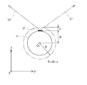
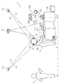
図1において、本実施例による安全制御システム1は、ロボット100を安全に制御するためのものであって、作業者Pの近傍でロボット100が協働作業を行う際に、作業者Pのとくに頭部Hを効果的に保護するためのシステムである。同図に示すように、ロボット100は、アーム(可動部)101、102と、アーム102の先端に取り付けられたエンドエフェクタ(可動部)103とを有しており、エンドエフェクタ103をテーブルTに対して繰り返し接近・離反させることにより作業を行っている。ロボット100の側方には、ロボットコントローラ110が配置されている。ロボットコントローラ110には、ロボット100の動作状態やエンドエフェクタ103の可動中心(TCP: Tool Center Point)等のリアルタイム情報が常時入力されている。なお、アーム101の基端軸の中心位置ORを中心として床面上に描いた半径Lの円の領域が危険領域として設定されており、半径Lとしては例えば2mに設定される。
In FIG. 1, the safety control system 1 according to the present embodiment is for safely controlling the
作業者Pの頭部H(好ましくは頭頂部)には、UWB(Ultra Wide Band: 超広帯域無線通信)タグUTが取り付けられている。UWBタグUTは作業者Pの例えば作業帽やヘルメット等に固定されている。作業者Pの上方には、UWBタグUTから発信されたUWB信号U1、U2をそれぞれ受信するUWBセンサ1(US1)(頭部位置検出手段)およびUWBセンサ2(US2)(頭部位置検出手段)が所定の間隔を隔てて設置されている。本安全制御システム1においては、UWBタグUTから発信されたUWB信号U1、U2の各UWBセンサUS1およびUS2に対する入射角度や到達時間差に基づいてUWBタグUT(したがって作業者Pの頭部H)のリアルタイムの三次元位置を測距する。 A UWB (Ultra Wide Band: Ultra Wide Band Wireless Communication) tag UT is attached to the head H (preferably the top) of the worker P. UWB tag U T is fixed, for example, work cap or helmet, etc. of the operator P. Above the operator P, UWB sensor 1 for receiving UWB tag U T UWB signals originating from U 1, U 2, respectively (U S1) (the head position detecting means) and UWB sensors 2 (U S2) ( Head position detecting means) are provided at predetermined intervals. In this safety control system 1, UWB tag U UWB signals transmitted from the T U 1, UWB tags based on the incident angle and the arrival time difference for each UWB sensors U S1 and U S2 of U 2 U T (hence the operator P The real-time three-dimensional position of the head H) is measured.
作業者Pの上方には、3D LiDAR(Light Detection And Ranging: 光検知・測距)10が設置されている。3D LiDAR10は、下方のテーブルTに向けてレーザーパルス101を出射し、戻ってくるレーザーパルスを受信する。本安全制御システム1においては、3D LiDAR10で受信されたレーザーパルスに基づいて、テーブルTの近傍領域の3Dイメージを作成する。すなわち、テーブルTの近傍において作業者Pの手部hおよびロボット100のエンドエフェクタ103のリアルタイム画像が作成される。これにより、作業中の作業者Pの手部hおよびロボット100のエンドエフェクタ103の位置関係が分かるようになっている。
Above the worker P, a 3D LiDAR (Light Detection And Ranging: light detection and ranging) 10 is installed. 3D LiDAR10 is a
危険領域の上方には、プロジェクタ11が設置されている。プロジェクタ11は、作業者Pの周囲の領域、例えば危険領域にプロジェクションマッピングを行うものであって、例えば黄色光や赤色光等の光111を照射することにより、危険領域に侵入する侵入者Iの注意を喚起する。さらに、危険領域の上方には、2Dカメラ12が設置されている。2Dカメラ12は、危険領域に侵入する侵入者Iを検知するためのものである。
A
次に、安全制御システム1の概略ブロック構成を図2に示す。
同図に示すように、安全制御システム1は、各種プログラミングやデータ入力、出力表示等を行うパソコン(PC)100と、これに接続されたプログラマブルコントローラ(PLC)130およびロボットコントローラ(RC)110とを備えている。PLC130/RC110には、ロボット制御プログラムが格納される。また、PLC130およびRC110には、UWBセンサ1(US1)、UWBセンサ2(US2)、3D LiDAR10、プロジェクタ11、2Dカメラ12、アクチュエータやモータを含むロボット駆動部140およびランプ/ブザー150が接続されている。
Next, a schematic block configuration of the safety control system 1 is shown in FIG.
As shown in FIG. 1, the safety control system 1 includes a personal computer (PC) 100 for performing various programming, data input, output display, etc., and a programmable controller (PLC) 130 and a robot controller (RC) 110 connected thereto. It has. The
図3および図4は、安全制御システム1の制御フローの一例を示している。
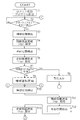
プログラムがスタートすると、図3のステップS1において、ロボット制御プログラムを読み込む。次に、ステップS2において、スタート/リセットボタンがONされるのを待つ。ステップS2でスタート/リセットボタンがONされれば、ステップS3に移行する。
3 and 4 show an example of a control flow of the safety control system 1.
When the program starts, a robot control program is read in step S1 of FIG. Next, in step S2, the process waits until the start / reset button is turned on. If the start / reset button is turned on in step S2, the process proceeds to step S3.
ステップS3では、頭部位置の検出を行う。この場合には、作業者P(図1)の頭部Hに取り付けられたUWBタグUTから発信されるUWB信号U1、U2をUWBセンサUS1およびUS2により受信し、UWB信号U1、U2のUWBセンサUS1およびUS2に対する入射角度や到達時間差に基づいて、UWBタグUT(したがって作業者Pの頭部H、正確には頭部Hの頭頂部)のリアルタイムの三次元位置を測距する。これにより、作業者Pの頭部Hの位置が検出される。次に、ステップS4では、ステップS3で検出された頭部Hの位置情報に基づいて、頭部保護領域HPを設定する。 In step S3, the head position is detected. In this case, received by the operator P UWB signals U 1, UWB and U 2 sensor U S1 and U S2 transmitted from UWB tag U T attached to the head H (FIG. 1), UWB signals U 1, based on the incident angle and the arrival time difference for UWB sensors U S1 and U S2 of U 2, real-time tertiary UWB tag U T (hence the head H of the operator P, the top of exactly the head H) Measure the original position. Thereby, the position of the head H of the worker P is detected. Next, in step S4, based on the position information of the detected head H in step S3, sets the head protection area H P.
頭部保護領域HPの設定について、図5および図6を用いて説明する。
図5は、図1から作業者Pの頭部Hを取り出して示す図であって、頭部Hの頭頂部にUWBタグUTが取り付けられた状態が示されている。上述したように、UWBタグUTから発信されたUWB信号U1、U2を受信して処理することにより、まず、UWBタグUTの三次元位置、したがって頭部Hの頭頂部の三次元位置が検出される(図3のステップS3)。なお、図5中には、UWBタグUTの三次元直交座標系(x、y、z)が記されているが、この座標系は、ロボット100の三次元直交座標系を所定方向に所定距離だけ平行移動したものに相当している。したがって、この場合、頭部Hの頭頂部の三次元位置は、ロボット100の三次元直交座標系を用いて表すことが可能である。
For configuration of the head protection area H P, it will be described with reference to FIGS.
Figure 5 is a diagram illustrating removed the head H of the operator P from FIG. 1, a state in which UWB tag U T is attached to the top portion of the head H is shown. As described above, by receiving and processing UWB signals U 1, U 2 originating from UWB tag U T, first, the three-dimensional position of the UWB tag U T, thus three-dimensional top of the head H The position is detected (Step S3 in FIG. 3). Note that in FIG. 5, a three-dimensional orthogonal coordinate system of UWB tag U T (x, y, z ) but are written, the coordinate system is given a three-dimensional orthogonal coordinate system of the
次に、頭部Hを球体と仮定し、頭頂部の位置から内方、つまりz軸のマイナス方向に距離dだけ離れた位置に頭部Hの中心OPがあると推定する。なお、この例では、簡略化のために、x、y軸方向へのずれは無視する。そして、図5中の二点鎖線で示すように、点OPを中心としかつ半径R(=d+α)の球面を描く。ここで、距離dに加える距離αは、頭部Hの個体差および測定誤差等を考慮しつつ頭部Hの周囲に頭部保護領域を設定するための頭部安全距離であって、例えば数十cm(一例として20〜30cm程度)に設定される(図5では図示の便宜上、距離αを小さめに記載している(図1についても同様))。これにより、図6に示すように、点OPを中心としかつ半径Rの球面で囲まれた斜線領域(三次元空間領域)が頭部保護領域HPとして設定される(図1参照)。 Next, the head H assumes that sphere, is estimated from the position of the parietal region inward, i.e. in the negative direction a distance d apart position in the z-axis and centered O P of the head H. In this example, for the sake of simplicity, deviations in the x and y axis directions are ignored. Then, as shown by the two-dot chain line in FIG. 5 depicts the spherical surface of the point O P centered Toshikatsu radius R (= d + α). Here, the distance α to be added to the distance d is a head safety distance for setting a head protection area around the head H in consideration of individual differences and measurement errors of the head H. The distance α is set to be 10 cm (for example, about 20 to 30 cm) (for the sake of convenience in FIG. 5, the distance α is set to be small (the same applies to FIG. 1)). Thus, as shown in FIG. 6, the hatched region surrounded the point O P spherical center Toshikatsu radius R (three-dimensional space region) is set as a head protection area H P (see FIG. 1).
次に、図3のステップS5において、ロボット100の可動部、すなわち、アーム101、102、エンドエフェクタ103がロボット100の稼動時に頭部保護領域HPと干渉するか否か、すなわち、アーム101、102、エンドエフェクタ103が頭部保護領域HPの外縁と接触するか否か、または頭部保護領域HPの内部まで進入するか否かを判断する。ステップS5において、干渉すると判断されれば、ステップS6に移行する。ステップS6では、ディスプレイに警告メッセージを表示させたり、警告灯を点灯させたりする警告表示を行う。ステップS6での処理後、ステップS2に戻り、ステップS2でスタート/リセットボタンがONされれば、再びステップS3〜ステップS5の処理を行う。
Next, in step S5 of FIG. 3, the movable portion of the
ステップS5において、アーム101、102、エンドエフェクタ103がロボット100の稼動時に頭部保護領域HPと干渉しないと判断されれば、ステップS7に移行して、ロボット100の運転を開始する。次に、ステップS8では、作業者Pの頭部Hの位置の検出を行い、これに続いてステップS9では、ステップS8で検出された頭部Hの位置情報に基づいて、頭部保護領域HPを設定する。ステップS8、S9の各処理は、上述したステップS3、S4の各処理と同様である。
In step S5, if it is determined that the
次に、ステップS10では、ロボット100のアーム101、102、エンドエフェクタ103がロボット100の稼動中に頭部保護領域HPと干渉するか否か、すなわち、アーム101、102、エンドエフェクタ103が頭部保護領域HPの外縁と接触するか否か、または頭部保護領域HPの内部まで進入するか否かを判断する。ステップS10において、干渉しないと判断されれば、ステップS8に戻り、ステップS8〜ステップS10の処理を繰り返す。すなわち、ロボット100の稼動中には、常時、作業者Pの頭部Hの位置が検出されてリアルタイムの三次元位置が測距されるとともに、その測距結果に基づいてリアルタイムの頭部保護領域HPが設定されており、ロボット100の稼動中にアーム101、102、エンドエフェクタ103が頭部保護領域HPと干渉しない限り、ロボット100の運転が継続して行われることになる。
Next, in step S10, the
ステップS10において、アーム101、102、エンドエフェクタ103が頭部保護領域HPと干渉すると判断されれば、プログラムは図4のステップS11に移行する。ステップS11では、ロボット100の運転を停止させる。
In step S10, the
次に、ステップS12では、スタート/リセットボタンがONされるのを待つ。スタート/リセットボタンがONされれば、ステップS13に移行して、作業者Pの頭部Hの位置を検出し、次に、ステップS14では、ステップS13で検出された頭部Hの位置情報に基づいて、頭部保護領域HPを設定する。ステップS13、S14の各処理は、上述したステップS3、S4の各処理と同様である。 Next, in step S12, the process waits until the start / reset button is turned on. If the start / reset button is turned on, the process proceeds to step S13, where the position of the head H of the worker P is detected. Then, in step S14, the position information of the head H detected in step S13 is added. based on, it sets the head protection area H P. The processes in steps S13 and S14 are the same as the processes in steps S3 and S4 described above.
次に、ステップS15では、ロボット100のアーム101、102、エンドエフェクタ103がロボット100の稼動時に頭部保護領域HPと干渉するか否か、すなわち、アーム101、102、エンドエフェクタ103が頭部保護領域HPの外縁と接触するか否か、または頭部保護領域HPの内部まで進入するか否かを判断する。ステップS15において、干渉すると判断されれば、ステップS16に移行する。ステップS16では、ディスプレイに警告メッセージを表示させたり、警告灯を点灯させたりする警告表示を行う。ステップS16での処理後、ステップS12に戻り、ステップS12でスタート/リセットボタンがONされれば、再びステップS13〜ステップS15の処理を行う。
Next, in step S15, the
ステップS15において、アーム101、102、エンドエフェクタ103がロボット100の稼動時に頭部保護領域HPと干渉しないと判断されれば、ステップS17に移行して、ロボット100の運転を再開する。運転再開後、プログラムは図3のステップS8に戻る。そして、ステップS10においてアーム101、102、エンドエフェクタ103が頭部保護領域HPと干渉すると判断されない限り、ステップS8〜ステップS10の処理が繰り返されて、ロボット100の運転が継続して行われる。
In step S15, the
ここで、図1に示したように、アーム101の基端軸の中心位置ORを中心として床面上に描いた半径Lの円の領域を危険領域として設定したが、この危険領域内に例えば侵入者Iが侵入したとき、この侵入は、危険領域の上方に設置された2Dカメラ12により検知される。上述したフローチャートでは、侵入者Iを検知した場合の制御についてまで触れていないが、この場合、例えば次のような制御を行うようにしてもよい。すなわち、侵入者Iが危険領域の外側にいるときはロボット100の可動部(アーム101、102、エンドエフェクタ103)を相対的に高出力で運転(例えば高速運転/大トルクで運転)し、侵入者Iが危険領域内にいるときはロボット100の可動部を相対的に低出力で運転(例えば中・低速運転/中・小トルクで運転)するように制御する。さらに、侵入者Iが危険領域内にいてロボット100に接近する場合には、侵入者Iとロボット100の距離に応じて可動部の速度をリニアに(つまり距離に比例して)または段階的に(つまりステップ状に)減速させるように制御する。これにより、安全性を確保しつつ、作業効率(例えば生産効率)を低下させることなく、効率よくロボット100を稼動できるようになる。
Here, as shown in FIG. 1 has been set an area of a circle of radius L drawn on the floor around the center position O R of the base end axis of the
また、ロボット100の稼動時には、3D LiDAR10を用いて作成された作業者Pの手部hおよびロボット100のエンドエフェクタ103のリアルタイム画像を解析することにより、エンドエフェクタ103が手部hと接触するか否かについても判断するようにしてもよく、その場合、接触すると判断された際に、エンドエフェクタ103を減速運転に切り替えたり、または停止させたりするようにしてもよい。
Also, when the
このように本実施例によれば、まず、作業者Pの頭部Hの位置を検出して頭部保護領域HPが設定され、次に、頭部保護領域HPとロボット100の可動部、つまりアーム101、102、エンドエフェクタ103の位置情報に基づいて、アーム101、102、エンドエフェクタ103が頭部保護領域HPと干渉しないようにロボット100が制御される、すなわち、ロボット100の運転開始前には警告表示を行い、ロボット100の稼動中にはロボット100を停止させるので、アーム101、102、エンドエフェクタ103が頭部Hと接触するのを確実に回避でき、頭部Hをロボット100から確実かつ効率的に保護できるようになる。
According to this embodiment, first, the operator positions the head H is detected and the head protection area H P of P is set, then, the movable portion of the head protection area H P and the
さらに、本実施例によれば、作業者Pの頭部Hの頭頂部の三次元位置は、ロボット100の三次元直交座標系を用いて表すことが可能であり、そのため、製造/組立等のラインの組み替え等の際には、ロボット100の可動部の位置データを変更することなく、作業者Pの頭部保護領域HPの位置をロボット100に認識させれば足りるので、ラインの組み換え等を容易に行えるようになる。
Further, according to the present embodiment, the three-dimensional position of the top of the head H of the worker P can be represented by using the three-dimensional orthogonal coordinate system of the
<第2の実施例>
図7ないし図10は、本発明の第2の実施例による安全制御システムを説明するための図である。これらの図において、前記第1の実施例と同一符号は同一または相当部分を示している。
<Second embodiment>
7 to 10 are views for explaining a safety control system according to a second embodiment of the present invention. In these figures, the same reference numerals as those in the first embodiment denote the same or corresponding parts.
この第2の実施例では、図7に示すように、作業者Pの頭部H(例えば左右の側頭部)に2つのUWBタグUT1、UT2が取り付けられている点、侵入者Iを検知するのに2Dカメラではなくレーザースキャナ15を設置している点、テーブルTの近傍領域において作業者Pの手部hとロボット100のエンドエフェクタ103の位置関係を示す画像を3D LiDAR10ではなく2Dカメラ12で取得するようにしている点が前記第1の実施例とは異なっている。このため、図8に示すように、PLC130およびRC110には、新たにレーザースキャナ15が接続されている。また、図7に示すように、UWBセンサ1(US1)は、UWBタグUT1、UT2から発信されたUWB信号U1、U1’を受信しており、UWBセンサ2(US2)は、UWBタグUT1、UT2から発信されたUWB信号U2、U2’を受信している。したがって、本安全制御システム1においては、UWBタグUT1、UT2から発信されたUWB信号U1、U1’、 U2、U2’のUWBセンサUS1およびUS2に対する入射角度や到達時間差に基づいてUWBタグUT1、UT2(したがって作業者Pの両側頭部)のリアルタイムの三次元位置を測距する。なお、前記第1の実施例で設置されていたプロジェクタ11は省略されているが、これは設置するようにしてもよい。
In the second embodiment, as shown in FIG. 7, the point that two UWB tags U T1 and U T2 are attached to the head H (for example, the right and left temporal regions) of the worker P; That the
本実施例による安全制御システム1の制御フローは、前記第1の実施例と同様であるが、前記第1の実施例の図3、図4中のステップS3、S8、S13における頭部位置の検出の仕方、およびステップS4、S9、S14における頭部保護領域の設定の仕方が前記第1の実施例とは異なっている。 The control flow of the safety control system 1 according to the present embodiment is the same as that of the first embodiment, except that the head position in steps S3, S8, and S13 in FIGS. The method of detection and the method of setting the head protection area in steps S4, S9 and S14 are different from those of the first embodiment.
本実施例による頭部保護領域HPの設定の仕方について、図9および図10を用いて説明する。
図9は、図7から作業者Pの頭部Hを取り出して示す図であって、頭部Hの左右2個所(ここでは両側頭部)の位置にそれぞれUWBタグUT1、UT2が取り付けられた状態が示されている(実線で示されたUWBタグUT1、UT2参照)。上述したように、UWBタグUT1から発信されたUWB信号U1、U2を受信して処理することにより、UWBタグUT1の三次元位置、したがって一方の側頭部の三次元位置が検出され、同様に、UWBタグUT2から発信されたUWB信号U1’、U2’を受信して処理することにより、UWBタグUT2の三次元位置、したがって他方の頭頂部の三次元位置が検出される。なお、図9中には、UWBタグUT1、UT2の三次元直交座標系(x、y、z)が記されているが、この座標系は、ロボット100の三次元直交座標系を所定方向に所定距離だけ平行移動したものに相当しており、そのため、前記第1の実施例と同様に、頭部Hの両側頭部の三次元位置は、ロボット100の三次元直交座標系を用いて表すことが可能である。
The method of setting the head protection area H P according to this embodiment will be described with reference to FIGS.
FIG. 9 is a diagram showing the head H of the worker P taken out from FIG. 7, and UWB tags U T1 and U T2 are attached to two positions on the left and right sides of the head H (here, both side heads). (See UWB tags U T1 and U T2 indicated by solid lines). As described above, UWB tag UWB signals originating from U T1 U 1, by receiving and processing U 2, three-dimensional position of the UWB tag U T1, thus detected three-dimensional position of one side of the head are, likewise, UWB tag U T2 UWB signals U 1 originating from ', U 2' by receiving and processing, three-dimensional position of the UWB tag U T2, hence the three-dimensional position of the other top portion Is detected. Note that FIG. 9 shows a three-dimensional orthogonal coordinate system (x, y, z) of the UWB tags U T1 and U T2. Therefore, as in the first embodiment, the three-dimensional positions of both sides of the head H are determined by using the three-dimensional orthogonal coordinate system of the
次に、頭部Hを球体と仮定したとき、球面上で相対する2個所の三次元位置が測距されたことになるので、これに基づいて、頭部Hの中心OP1および仮想半径dを求めることができる。そして、図9中の二点鎖線で示すように、点OP1を中心としかつ半径R(=d+α)の球面を描く。ここで、仮想半径dに加える距離αは、前記第1の実施例の場合と同様に、頭部Hの個体差および測定誤差等を考慮しつつ頭部Hの周囲に頭部保護領域を設定するための頭部安全距離であって、例えば数十cm(一例として20〜30cm程度)に設定される(図9では図示の便宜上、距離αを小さめに記載している(図7についても同様))。これにより、図10に示すように、点OP1を中心としかつ半径Rの球面で囲まれた斜線領域(三次元空間領域)が頭部保護領域HPとして設定される(図7参照)。 Next, assuming that the head H is a sphere, two opposing three-dimensional positions on the spherical surface have been measured, and based on this, the center OP1 of the head H and the virtual radius d Can be requested. Then, as shown by the two-dot chain line in FIG. 9 depicts a sphere of the point O P1 center Toshikatsu radius R (= d + α). Here, the distance α added to the virtual radius d sets the head protection area around the head H in consideration of the individual difference and the measurement error of the head H as in the case of the first embodiment. The head safety distance is set to, for example, several tens of cm (for example, about 20 to 30 cm) (in FIG. 9, for convenience of illustration, the distance α is described as being small (the same applies to FIG. 7). )). Thus, as shown in FIG. 10, the hatched region surrounded the point O P1 spherical center Toshikatsu radius R (three-dimensional space region) is set as a head protection area H P (see FIG. 7).
なお、図9中に一点鎖線で示すように、UWBタグUT1、UT2が同図中の実線位置よりも若干頭頂部寄りの位置に配置されていた場合には、これらのUWBタグUT1、UT2からUWBセンサUS1、UWBセンサUS2に向けて発信される各UWB信号がなす角度θを求めることにより、中心OP1を求めることが可能である。 If the UWB tags U T1 and U T2 are arranged at positions slightly closer to the top of the head than the solid line positions in FIG. 9 as indicated by the dashed line in FIG. 9, these UWB tags U T1 , U T2 to the UWB sensor U S1 and the UWB sensor U S2 to determine the angle θ formed by each UWB signal, thereby obtaining the center OP1 .
また、ロボット100の稼動時には、2Dカメラ12で撮影された作業者Pの手部hおよびロボット100のエンドエフェクタ103のリアルタイム画像を解析することにより、エンドエフェクタ103が手部hと接触するか否かについても判断するようにしてもよく、その場合、接触すると判断された際に、エンドエフェクタ103を減速運転に切り替えたり、または停止させたりするようにしてもよい。
When the
このように本実施例によれば、前記第1の実施例と同様に、まず、作業者Pの頭部Hの位置を検出して頭部保護領域HPが設定され、次に、頭部保護領域HPとロボット100の可動部、つまりアーム101、102、エンドエフェクタ103の位置情報に基づいて、アーム101、102、エンドエフェクタ103が頭部保護領域HPと干渉しないようにロボット100が制御されるので、アーム101、102、エンドエフェクタ103が頭部Hと接触するのを確実に回避でき、頭部Hをロボット100から確実かつ効率的に保護できるようになる。しかも、本実施例によれば、頭部Hの2個所の位置を検出するので、正確に頭部保護領域HPを設定できるようになる。
According to this embodiment, the similar to the first embodiment, first, the head protection area H P position detection to the head H of the operator P is set, then the head the movable portion of the protection area H P and the
さらに、本実施例によれば、作業者Pの頭部Hの両側頭部の三次元位置は、ロボット100の三次元直交座標系を用いて表すことが可能であり、そのため、製造/組立等のラインの組み替え等の際には、ロボット100の可動部の位置データを変更することなく、作業者Pの頭部保護領域HPの位置をロボット100に認識させれば足りるので、ラインの組み換え等を容易に行えるようになる。
Furthermore, according to the present embodiment, the three-dimensional positions of the heads on both sides of the head H of the worker P can be represented using the three-dimensional orthogonal coordinate system of the
<第3の実施例>
図11および図12は、本発明の第3の実施例による安全制御システムを説明するための図である。これらの図において、前記第1、第2の実施例と同一符号は同一または相当部分を示している。
<Third embodiment>
FIG. 11 and FIG. 12 are views for explaining a safety control system according to a third embodiment of the present invention. In these figures, the same reference numerals as those in the first and second embodiments denote the same or corresponding parts.
前記第2の実施例では、テーブルTの近傍領域において作業者Pの手部hとロボット100のエンドエフェクタ103の位置関係を示すデータを2Dカメラ12で撮影した画像から取得するようにした例を示したが、この第3の実施例では、手部h(または手部hに装着した手袋)にRFIDタグRftを、エンドエフェクタ103にRFIDタグアンテナRfaをそれぞれ取り付け、RFIDタグアンテナRfaによりRFIDタグRftを検知することにより、RFIDタグRftの位置(したがって手部h)の位置を検出している。このため、図12に示すように、PLC130およびRC110には、新たにRFIDタグアンテナRfaが接続されている。
In the second embodiment, an example in which data indicating the positional relationship between the hand h of the worker P and the
本実施例による安全制御システム1の制御フローは、前記第2の実施例と同様であって、頭部位置の検出の仕方や頭部保護領域の設定の仕方についても同様である。したがって、本実施例によれば、前記第2の実施例と同様に、まず、作業者Pの頭部Hの位置を検出して頭部保護領域HPが設定され、次に、頭部保護領域HPとロボット100のアーム101、102、エンドエフェクタ103の位置情報に基づいて、アーム101、102、エンドエフェクタ103が頭部保護領域HPと干渉しないようにロボット100が制御されるので、アーム101、102、エンドエフェクタ103が頭部Hと接触するのを確実に回避でき、頭部Hをロボット100から確実かつ効率的に保護できるようになる。しかも、本実施例によれば、頭部Hの2個所の位置を検出するので、頭部Hの動きに応じてより正確に頭部保護領域HPを設定できるようになる。
The control flow of the safety control system 1 according to the present embodiment is the same as that in the second embodiment, and the same applies to the method of detecting the head position and the method of setting the head protection area. Therefore, according to this embodiment, the similar to the second embodiment, first, the head protection area H P position detection to the head H of the operator P is set, then head protecting region H P and the
さらに、本実施例によれば、作業者Pの頭部Hの両側頭部の三次元位置は、ロボット100の三次元直交座標系を用いて表すことが可能であり、そのため、製造/組立等のラインの組み替え等の際には、ロボット100の可動部の位置データを変更することなく、作業者Pの頭部保護領域HPの位置をロボット100に認識させれば足りるので、ラインの組み換え等を容易に行えるようになる。
Furthermore, according to the present embodiment, the three-dimensional positions of the heads on both sides of the head H of the worker P can be represented using the three-dimensional orthogonal coordinate system of the
また、ロボット100の稼動時には、RFIDタグアンテナRfaでRFIDタグRftの位置を検出することにより、エンドエフェクタ103が手部hと接触するか否かについても判断することができ、その場合、接触すると判断された場合に、エンドエフェクタ103を減速運転に切り替えたり、または停止させたりすることが可能である。これにより、頭部Hのみならず、手部hについても確実かつ効率的に保護できるようになる。
Also, when the
<第4の実施例>
図13ないし図16は、本発明の第4の実施例による安全制御システムを説明するための図である。これらの図において、前記第1ないし第3の実施例と同一符号は同一または相当部分を示している。
<Fourth embodiment>
FIGS. 13 to 16 are views for explaining a safety control system according to a fourth embodiment of the present invention. In these figures, the same reference numerals as those in the first to third embodiments denote the same or corresponding parts.
前記第3の実施例では、テーブルTの近傍領域においてロボット100のエンドエフェクタ103に対する作業者Pの手部hの相対位置を検出する際に、エンドエフェクタ103側のRFIDタグアンテナRfaが手部h側のRFIDタグRftを検知することでRFIDタグRftの位置(したがって手部h)の位置を検出するようにした例を示したが、この第4の実施例では、手部h(または手部hに装着した手袋の例えば甲部分)にUWBタグUT3を取り付け、UWBタグUT3から発信されたUWB信号U3、U3’をそれぞれUWBセンサUS1、US2(他部位位置検出手段)で受信するようにしている。本安全制御システム1においては、UWBタグUT3から発信されたUWB信号U3、U3’のUWBセンサUS1およびUS2に対する入射角度や到達時間差に基づいてUWBタグUT3(したがって作業者Pの手部h、正確には手部hの甲部分)のリアルタイムの三次元位置を測距する。また、安全制御システム1の制御ブロック構成は図14に示すとおりである。
In the third embodiment, when the relative position of the hand h of the worker P with respect to the
次に、安全制御システム1の制御フローの一例について、図15および図16を用いて説明する。
プログラムがスタートすると、図15のステップT1において、ロボット制御プログラムを読み込む。次に、ステップT2において、スタート/リセットボタンがONされるのを待つ。ステップT2でスタート/リセットボタンがONされれば、ステップT3に移行する。
Next, an example of a control flow of the safety control system 1 will be described with reference to FIGS.
When the program starts, a robot control program is read in step T1 in FIG. Next, in step T2, the process waits until the start / reset button is turned on. If the start / reset button is turned on in step T2, the process proceeds to step T3.
ステップT3では、頭部位置の検出を行う。この場合には、作業者P(図13)の頭部Hの2個所の位置(例えば両側頭部の位置)に取り付けられたUWBタグUT1、UT2からそれぞれ発信されるUWB信号U1、U2およびU1’、U2’をUWBセンサUS1およびUS2により受信し、UWB信号U1、U1’およびU2、U2’のUWBセンサUS1およびUS2に対する入射角度や到達時間差に基づいて、UWBタグUT1、UT2(したがって作業者Pの頭部H、正確には頭部Hの両側頭部)のリアルタイムの三次元位置を測距する。これにより、作業者Pの頭部Hの両側頭部の位置が検出される。次に、ステップT4では、ステップT3で検出された頭部Hの位置情報に基づいて、頭部保護領域HPを設定する。
In step T3, the head position is detected. In this case, UWB signals U 1 , U 1 transmitted from UWB tags U T1 and U T2 attached at two positions (for example, positions on both sides of the head) of the head H of the worker P (FIG. 13), received by the U 2 and U 1 ', U 2' UWB sensors U S1 and U S2, the angle of incidence or reach for
頭部保護領域HPの設定については、前記第2の実施例の図9、図10に示したものと同様である。すなわち、UWBタグUT1から発信されたUWB信号U1、U2を受信して処理することにより、UWBタグUT1の三次元位置、したがって一方の側頭部の三次元位置が検出され、同様に、UWBタグUT2から発信されたUWB信号U1’、U2’を受信して処理することにより、UWBタグUT2の三次元位置、したがって他方の側頭部の三次元位置が検出される。次に、頭部Hを球体と仮定したとき、球面上で相対する2個所の三次元位置が測距されたことになるので、これに基づいて、頭部Hの中心OP1および仮想半径が求まる。そして、頭部Hの個体差および測定誤差等を考慮しつつ頭部Hの周囲に頭部保護領域を設定するための頭部安全距離αを設定するとともに、この距離αを加味した三次元空間領域を頭部保護領域HPとして設定する(図13参照)。 For configuration of the head protection area H P, the 9 of the second embodiment is the same as that shown in FIG. 10. That is, by receiving and processing UWB signals U 1, U 2 originating from UWB tag U T1, three-dimensional position of the UWB tag U T1, thus detected three-dimensional position of one side of the head, similar to, UWB tag U T2 UWB signals U 1 originating from ', U 2' by receiving and processing, three-dimensional position of the UWB tag U T2, hence the three-dimensional position of the other side of the head is detected You. Next, assuming that the head H is a sphere, two opposite three-dimensional positions on the spherical surface are measured, and based on this, the center OP1 and the virtual radius of the head H are determined. I get it. Then, a head safety distance α for setting a head protection area around the head H is set in consideration of individual differences and measurement errors of the head H, and a three-dimensional space considering this distance α is set. setting the area as a head protection area H P (see FIG. 13).
次に、図15のステップT5において、手部位置の検出を行う。この場合には、作業者P(図13)の手部hに取り付けられたUWBタグUT3から発信されるUWB信号U3、U3’をUWBセンサUS1およびUS2により受信し、UWB信号U3、U3’のUWBセンサUS1およびUS2に対する入射角度や到達時間差に基づいて、UWBタグUT3(したがって作業者Pの手部h、正確には手部hの甲部分)のリアルタイムの三次元位置を測距する。これにより、作業者Pの手部hの位置が検出される。次に、ステップT6では、ステップT5で検出された手部hの位置情報に基づいて、手部保護領域hPを設定する。 Next, in step T5 in FIG. 15, the hand position is detected. In this case, UWB signals U 3 and U 3 ′ transmitted from the UWB tag U T3 attached to the hand h of the worker P (FIG. 13) are received by the UWB sensors U S1 and U S2 , and the UWB signal is received. Based on the incident angles and arrival time differences of U 3 and U 3 ′ with respect to the UWB sensors U S1 and U S2 , the real-time of the UWB tag U T3 (therefore, the hand h of the worker P, more precisely, the back of the hand h). To measure the three-dimensional position of. Thereby, the position of the hand h of the worker P is detected. Next, in step T6, based on the position information of the detected hand portion h in step T5, set the hand portion protected area h P.
手部保護領域hPの設定については、上述したように、UWBタグUT3から発信されたUWB信号U3、U3’を受信して処理することにより、まず、UWBタグUT3の三次元位置、つまり手部h(正確には手部hの甲部分)の三次元位置が検出される(図15のステップT5)。次に、手部hを球体と仮定したとき、球面上の三次元位置が測距されたことになるので、図5と同様の手法で、手部hの中心および仮想半径を求めることができる。そして、手部hの個体差および測定誤差等を考慮しつつ手部hの周囲に手部保護領域を設定するための手部安全距離(他部位安全距離)βを設定する。この手部安全距離βとしては、例えば数cm〜数十cm(一例として5〜10cm程度)に設定される。手部安全距離βは頭部安全距離αよりも小さくなっている。次に、仮想半径に手部安全距離βを加味した三次元空間領域を手部保護領域hPとして手部hの周りに設定する(図13参照)。 The setting of the hand portion protected area h P, as described above, by receiving and processing UWB tag U T3 UWB signal U 3 originating from, U 3 ', first, three-dimensional UWB tag U T3 The position, that is, the three-dimensional position of the hand h (more precisely, the upper part of the hand h) is detected (step T5 in FIG. 15). Next, assuming that the hand h is a sphere, the three-dimensional position on the spherical surface has been measured, so that the center and the virtual radius of the hand h can be obtained in the same manner as in FIG. . Then, a hand safety distance (other part safety distance) β for setting a hand protection area around the hand h is set in consideration of individual differences and measurement errors of the hand h. The hand safety distance β is set, for example, to several cm to several tens cm (for example, about 5 to 10 cm). The hand safety distance β is smaller than the head safety distance α. Next, set around the hand portion h a three-dimensional space region in consideration of the hand portion safety distance β to the virtual radius as the hand protection area h P (see FIG. 13).
次に、ステップT7において、ロボット100の可動部、つまりアーム101、102、エンドエフェクタ103がロボット100の稼動時に頭部保護領域HPまたは手部保護領域hpと干渉するか否か、すなわち、アーム101、102、エンドエフェクタ103が頭部保護領域HPまたは手部保護領域hpの外縁と接触するか否か、または頭部保護領域HPまたは手部保護領域hpの内部まで進入するか否かを判断する。ステップT7において、干渉すると判断されれば、ステップT8に移行する。ステップT8では、ディスプレイに警告メッセージを表示させたり、警告灯を点灯させたりする警告表示を行う。ステップT8での処理後、ステップT2に戻り、ステップT2でスタート/リセットボタンがONされれば、再びステップT3〜ステップT7の処理を行う。
Next, in step T7, the movable part of the
ステップT7において、アーム101、102、エンドエフェクタ103がロボット100の稼動時に頭部保護領域HPまたは手部保護領域hpと干渉しないと判断されれば、ステップT9に移行して、ロボット100の運転を開始する。次に、ステップT10では、作業者Pの頭部Hの位置の検出を行い、これに続いてステップT11では、ステップT10で検出された頭部Hの位置情報に基づいて、頭部保護領域HPを設定する。ステップT10、T11の各処理は、上述したステップT3、T4の各処理と同様である。
In step T7, when it is determined that the
次に、ステップT12では、作業者Pの手部hの位置の検出を行い、これに続いてステップT13では、ステップT12で検出された手部hの位置情報に基づいて、手部保護領域hPを設定する。ステップT12、T13の各処理は、上述したステップT5、T6の各処理と同様である。 Next, in step T12, the position of the hand h of the worker P is detected. Subsequently, in step T13, the hand protection area h is detected based on the position information of the hand h detected in step T12. Set P. The processes in steps T12 and T13 are the same as the processes in steps T5 and T6 described above.
次に、図16のステップT14では、ロボット100のアーム101、102、エンドエフェクタ103がロボット100の稼動中に頭部保護領域HPまたは手部保護領域hpと干渉するか否か、すなわち、アーム101、102、エンドエフェクタ103が頭部保護領域HPまたは手部保護領域hpの外縁と接触するか否か、または頭部保護領域HPまたは手部保護領域hpの内部まで進入するか否かを判断する。ステップT14において、干渉しないと判断されれば、図15のステップT10に戻り、ステップT10〜ステップT14の処理を繰り返す。すなわち、ロボット100の稼動中には、常時、作業者Pの頭部Hおよび手部hの位置が検出されてそれぞれのリアルタイムの三次元位置が測距されるとともに、それらの測距結果に基づいてリアルタイムの頭部保護領域HPおよび手部保護領域hpが設定されており、ロボット100の稼動中にアーム101、102、エンドエフェクタ103が頭部保護領域HPまたは手部保護領域hpと干渉しない限り、ロボット100の運転が継続して行われることになる。
Next, in step T14 in FIG. 16, the
ステップT14において、アーム101、102、エンドエフェクタ103が頭部保護領域HPまたは手部保護領域hpと干渉すると判断されれば、ステップT15に移行する。ステップT15では、ロボット100の運転を停止させる。
In step T14, the
次に、ステップT16では、スタート/リセットボタンがONされるのを待つ。スタート/リセットボタンがONされれば、ステップT17に移行して、作業者Pの頭部Hの位置を検出し、次に、ステップT18では、ステップT17で取得された頭部Hの位置情報に基づいて、頭部保護領域HPを設定する。ステップT17、T18の各処理は、上述したステップT3、T4の各処理と同様である。 Next, in step T16, the process waits until the start / reset button is turned on. If the start / reset button is turned on, the process proceeds to step T17 to detect the position of the head H of the worker P. Next, in step T18, the position information of the head H obtained in step T17 is added to the position information. based on, it sets the head protection area H P. Each process in steps T17 and T18 is the same as each process in steps T3 and T4 described above.
次に、ステップT19では、作業者Pの手部hの位置の検出を行い、これに続いてステップT20では、ステップT19で取得された手部hの位置情報に基づいて、手部保護領域hPを設定する。ステップT19、T20の各処理は、上述したステップT5、T6の各処理と同様である。 Next, in step T19, the position of the hand h of the worker P is detected. Subsequently, in step T20, based on the position information of the hand h obtained in step T19, the hand protected area h is detected. Set P. The processes in steps T19 and T20 are the same as the processes in steps T5 and T6 described above.
次に、ステップT21では、ロボット100のアーム101、102、エンドエフェクタ103がロボット100の稼動時に頭部保護領域HPまたは手部保護領域hpと干渉するか否か、すなわち、アーム101、102、エンドエフェクタ103が頭部保護領域HPまたは手部保護領域hpの外縁と接触するか否か、または頭部保護領域HPまたは手部保護領域hpの内部まで進入するか否かを判断する。ステップT21において、干渉すると判断されれば、ステップT22に移行する。ステップT22では、ディスプレイに警告メッセージを表示させたり、警告灯を点灯させたりする警告表示を行う。ステップT22での処理後、ステップT16に戻り、ステップT16でスタート/リセットボタンがONされれば、再びステップT17〜ステップT21の処理を行う。
Next, in step T21, the
ステップT21において、アーム101、102、エンドエフェクタ103がロボット100の稼動時に頭部保護領域HPまたは手部保護領域hpと干渉しないと判断されれば、ステップT23に移行して、ロボット100の運転を再開する。運転再開後、プログラムは図15のステップT10に戻る。そして、ステップT14においてアーム101、102、エンドエフェクタ103が頭部保護領域HPまたは手部保護領域hpと干渉すると判断されない限り、ステップT10〜ステップT14の処理が繰り返されて、ロボット100の運転が継続して行われる。
In step T21, if it is determined that the
このように本実施例によれば、まず、作業者Pの頭部Hおよび手部hの位置を検出して頭部保護領域HPおよび手部保護領域hpが設定され、次に、頭部保護領域HPおよび手部保護領域hpとロボット100の可動部、つまりアーム101、102、エンドエフェクタ103の位置情報に基づいて、アーム101、102、エンドエフェクタ103が頭部保護領域HPおよび手部保護領域hpと干渉しないようにロボット100が制御される、すなわち、ロボット100の運転開始前には警告表示を行い、ロボット100の稼動中にはロボット100を停止させるので、アーム101、102、エンドエフェクタ103が頭部H、手部保護領域hpと接触するのを確実に回避でき、頭部H、手部hをロボット100から確実かつ効率的に保護できるようになる。しかも、本実施例によれば、頭部Hに関しては2個所の位置を検出するので、正確に頭部保護領域HPを設定できるようになる。
According to this embodiment, first, the head H and detects a position of the hand portion h and a head protection area of the operator P H P and the hand protection area h p is set, then the head the movable portion of the section protection area H P and the hand protected area h p and the
さらに、本実施例によれば、作業者Pの頭部Hの両側頭部の三次元位置は、ロボット100の三次元直交座標系を用いて表すことが可能であり、そのため、製造/組立等のラインの組み替え等の際には、ロボット100の可動部の位置データを変更することなく、作業者Pの頭部保護領域HPおよび手部保護領域hpの位置をロボット100に認識させればよいので、ラインの組み換え等を容易に行えるようになる。
Furthermore, according to the present embodiment, the three-dimensional positions of the heads on both sides of the head H of the worker P can be represented using the three-dimensional orthogonal coordinate system of the
しかも、本実施例によれば、手部安全距離βが頭部安全距離αよりも小さく設定されているので、ロボット100の可動部が手部hに接近して作業を行うことができるとともに、手部hに接近したことでロボット100の運転が頻繁に停止するいわゆるチョコ停止を防止でき、これにより、ロボット100の作業効率を向上できる。逆の言い方をすれば、頭部安全距離αが手部安全距離βよりも大きく設定されているので、頭部Hにロボット100の可動部が衝突または接触するのを確実に回避でき、頭部Hをロボット100からより確実に保護できるようになる。
Moreover, according to the present embodiment, the hand safety distance β is set to be smaller than the head safety distance α, so that the movable part of the
〔第1の変形例〕
前記第1ないし第4の実施例では、作業者Pの頭部Hの位置を検出するのに、2つのUWBセンサUS1、US2を用いた例を示したが、UWBセンサは3つ(またはそれ以上)設置するようにしてもよく、これにより、一層高精度の位置検出が可能になる。
[First Modification]
In the first to fourth embodiments, two UWB sensors U S1 and U S2 are used to detect the position of the head H of the worker P. However, three UWB sensors ( Or more), which allows for more accurate position detection.
〔第2の変形例〕
前記第1ないし第4の実施例では、UWBタグUT、UT1、UT2、UT3およびUWBセンサUS1、US2を用いて、作業者Pの頭部H、手部hの位置を検出するようにした例を示したが、本発明の適用はこれに限定されない。その他のセンサ(例えば高精度レーザー距離センサ等)を用いてもよく、あるいはカメラと画像処理装置を併用するようにしてもよい。
[Second Modification]
In the first to fourth embodiments, the positions of the head H and the hand h of the worker P are determined using the UWB tags U T , U T1 , U T2 , U T3 and the UWB sensors U S1 , U S2. Although an example in which detection is performed has been described, the application of the present invention is not limited to this. Other sensors (for example, a high-precision laser distance sensor) may be used, or a camera and an image processing device may be used in combination.
〔第3の変形例〕
前記第1ないし第4の実施例では、頭部保護領域HPとして球状領域を用いた例を示したが、本発明の適用はこれに限定されない。球状領域以外の三次元空間領域(例えば多数の微小平面からなる球面状空間または回転楕円状空間等)を用いるようにしてもよい。
[Third Modification]
In the first to fourth embodiments, an example of using a globular region as a head protection area H P, the application of the present invention is not limited thereto. A three-dimensional space area other than the spherical area (for example, a spherical space or a spheroidal space composed of a number of minute planes) may be used.
〔第4の変形例〕
前記第1ないし第4の実施例では、頭部Hの中心OP、OP1を求めることで中心OP、OP1の回りの球状領域を頭部保護領域HPとして設定した例を示したが、本発明の適用はこれに限定されない。頭部Hの中心OPを求めることなく、UWBタグUT、UT1、UT2の三次元位置、つまり頭部Hの頭頂部、両側頭部の三次元位置を基準とし、その周囲に頭部Hの個体差および測定誤差等を考慮した大きさの三次元空間領域を想定して、これを頭部保護領域HPに設定するようにしてもよい。
[Fourth Modification]
In the first to fourth embodiments, an example in which the center O P, the center O P by obtaining O P1, around the globular region of O P1 set as a head protection area H P of the head H However, application of the present invention is not limited to this. Without obtain the center O P of the head H, the three-dimensional position of the UWB tag U T, U T1, U T2 , i.e. the top portion of the head H, as a reference the three-dimensional position of both sides the head, head around assuming a three-dimensional spatial region of the individual difference and the size in consideration of measurement error and the like parts H, which may be set on the head protection area H P.
〔第5の変形例〕
前記第1の実施例の図3、図4および前記第4の実施例の図15、図16で示したフローチャートは、制御フローの一例を示しており、その他の制御フローを採用するようにしてもよい。例えば、前記第4の実施例においては、図16のステップT14、T15に示すように、ロボット100の可動部が手部保護領域hpと干渉すると判断された場合に、頭部保護領域HPとの干渉の場合と同様にして、ロボット100をすぐに停止させるようにした例を示したが、本発明の適用はこれに限定されない。例えば、ロボット100の可動部が手部保護領域hpと干渉する場合にロボット100を停止させるのではなく、減速運転させるようにしてもよく、あるいは、ロボット100の可動部が手部保護領域hPの外縁と接触するだけの場合には、ロボット100を通常運転させ、ロボット100の可動部が手部保護領域hPの内部まで進入する場合に限って、ロボット100を減速運転または停止させるようにしてもよく、種々のやり方が考えられる。
[Fifth Modification]
The flowcharts shown in FIGS. 3 and 4 of the first embodiment and FIGS. 15 and 16 of the fourth embodiment show an example of the control flow, and other control flows are adopted. Is also good. For example, in the above fourth embodiment, as shown in step T14, T15 in FIG. 16, when the movable part of the
〔第6の変形例〕
前記第1ないし第4の実施例では、頭部Hの頭頂部、両側頭部の三次元位置の検出の際に使用される三次元直交座標系として、ロボット100の三次元直交座標系を所定方向に所定距離だけ平行移動したものを用いることにより、作業者Pの頭部保護領域HPの位置をロボット100に認識させるようにした例を示したが、本発明の適用はこれに限定されない。頭部Hの頭頂部、両側頭部の位置とロボット100のアーム101、102、エンドエフェクタ103の位置を3D LiDAR10や2Dカメラ12等でそれぞれ検出することにより、ロボット100に対する頭部Hの相対位置を検出し、作業者Pの頭部保護領域HPの位置をロボット100に認識させるようにしてもよい。また、ロボット100の原点位置に別のUWBタグ(図示せず)を取り付け、当該UWBタグから発信されたUWB信号を同じUWBセンサUS1、US2を用いて受信することにより、ロボット100の三次元直交座標系に対する頭部Hの位置を検出するようにしてもよい。あるいは、ロボット100のアーム101、102、エンドエフェクタ103の各位置にそれぞれUWBタグ(図示せず)を取り付け、これらのUWBタグから発信されたUWB信号を同じUWBセンサUS1、US2を用いて受信することにより、ロボット100に対する頭部Hの相対位置を検出するようにしてもよい。
[Sixth Modification]
In the first to fourth embodiments, the three-dimensional orthogonal coordinate system of the
〔第7の変形例〕
前記第1ないし第4の実施例では、危険領域内に侵入者(つまり人)Iが侵入した例を示したが、2Dカメラ12、レーザースキャナ15による検知は、人に限らず物(例えばAGV(Automated Guided Vehicle: 無人搬送車)等)も可能である。この場合、例えばAGVにUWBタグを取り付けておくことにより、侵入体が人ではないことがロボット100側で識別できるので、AGVの接近によってはロボット100の運転速度を減速させる必要がなくなり、これにより、作業効率を低下させることなく、ロボット100を稼動できるようになる。このようにして、侵入体が人か物かに応じて適切な制御が行える。
[Seventh Modification]
In the first to fourth embodiments, an example has been described in which an intruder (that is, a person) I has entered the dangerous area. However, the detection by the
<第8の変形例>
前記第2ないし第4の実施例では、危険領域内への侵入者Iの侵入をレーザースキャナ15により検知するようにした例を示したが、レーザースキャナは侵入者Iまでの距離を測定することができるので、レーザースキャナ15を採用することにより、侵入者Iとロボット100との距離に応じてロボット100を効率よく運転(例えばリニアに減速したり、段階的に減速したりする等)できるようになる。また、一般にレーザースキャナは安全機器なので、侵入者IにもUWBタグを付けてこれをUWBセンサUS1、US2で検出するようにすれば、レーザースキャナ15の正常動作時にUWBセンサUS1、US2が反応しない場合にUWBセンサUS1、US2が故障していることが分かり、UWBセンサUS1、US2の故障診断を行えるようになって、より安全な制御システムを構築できる。なお、UWBセンサUS1、US2に他の安全機器を組み合わせるようにしてもよい。
<Eighth Modification>
In the second to fourth embodiments, an example has been described in which the intrusion of the intruder I into the dangerous area is detected by the
<第9の変形例>
前記第1および第2の実施例では、3D LiDAR10や2Dカメラ12を採用したが、これらの代わりに3Dカメラやステレオカメラ等を採用するようにしてもよい。また、前記第1の実施例では3D LiDAR10により、前記第2の実施例では2Dカメラ12により、前記第3の実施例ではRFIDタグRftおよびRFIDタグアンテナRfaにより、作業者Pの手部hとロボット100のエンドエフェクタ103の位置関係を検出するようにした例を示したが、これら3D LiDAR10、2Dカメラ12、またはRFIDタグRftおよびRFIDタグアンテナRfaのいずれかを用いて、作業者Pの手部hの位置を直接検出するようにしてもよい。
<Ninth Modification>
Although the
<第10の変形例>
前記第4の実施例では、作業者Pの頭部H以外の他部位の位置を検出する例として、作業者Pの手部hを検出するようにしたものを示したが、本発明は手部h以外の体の部位の位置を検出するものにも同様に適用可能である。また、前記第4の実施例では、手部保護領域hpとして、球状領域を用いた例を示したが、本発明の適用はこれに限定されない。球状領域以外の三次元空間領域(例えば多数の微小平面からなる球面状空間または回転楕円状空間等)を用いるようにしてもよい。
<Tenth Modification>
In the fourth embodiment, an example in which the hand h of the worker P is detected as an example of detecting the position of a part other than the head H of the worker P has been described. The present invention is similarly applicable to a device for detecting the position of a body part other than the part h. Further, in the fourth embodiment, as the hand protection area h p, although an example of using a spherical region, application of the present invention is not limited thereto. A three-dimensional space area other than the spherical area (for example, a spherical space or a spheroidal space composed of a number of minute planes) may be used.
<第11の変形例>
前記第1ないし第4の実施例では、作業者Pの体に取り付けるUWBタグを作業者Pの体の部位の位置検出のみに使用した例を示したが、UWBタグから発信されるUWB信号に作業者PのID情報(例えば作業の熟練度のデータ等)を重畳するようにしてもよく、その場合には、作業者Pのレベルに応じて効率よくロボット100の運転を制御できるようになる。
<Eleventh modification>
In the first to fourth embodiments, the example in which the UWB tag attached to the body of the worker P is used only for detecting the position of the body part of the worker P, but the UWB signal transmitted from the UWB tag is The ID information of the worker P (for example, data on the skill level of the work) may be superimposed. In this case, the operation of the
〔その他の変形例〕
上述した実施例および各変形例はあらゆる点で本発明の単なる例示としてのみみなされるべきものであって、限定的なものではない。本発明が関連する分野の当業者は、本明細書中に明示の記載はなくても、上述の教示内容を考慮するとき、本発明の精神および本質的な特徴部分から外れることなく、本発明の原理を採用する種々の変形例やその他の実施例を構築し得る。
[Other modifications]
The above-described embodiments and modifications are to be considered in all respects only as illustrative of the present invention, and not restrictive. Those skilled in the art to which the present invention pertains may, without considering the teachings herein, depart from the spirit and essential characteristics of the invention without departing from the spirit and essential characteristics thereof. Various modifications and other embodiments employing the principle of the present invention can be constructed.
〔他の適用例〕
前記実施例および前記各変形例では、本発明による安全制御システムが適用される機械として、垂直多関節ロボットを例にとって説明したが、本発明の適用はこれに限定されない。本発明による安全制御システムは、その他のロボット、例えば水平多関節ロボットやスカラロボット等にも適用でき、さらには、パワーショベル等の産業車両にも適用できる。
[Other application examples]
In the above-described embodiment and each of the modifications, a vertical articulated robot has been described as an example of a machine to which the safety control system according to the present invention is applied. However, the application of the present invention is not limited to this. The safety control system according to the present invention can be applied to other robots, for example, a horizontal articulated robot, a SCARA robot, and the like, and further can be applied to an industrial vehicle such as a power shovel.
本発明は、人の頭部を機械から確実に保護するための安全制御システムに有用である。 INDUSTRIAL APPLICABILITY The present invention is useful for a safety control system for reliably protecting a person's head from a machine.
1: 安全制御システム
100: ロボット(機械)
101、102: アーム(可動部)
103: エンドエフェクタ(可動部)
110: ロボットコントローラ(制御手段)
130: プログラマブルコントローラ(制御手段)
US1: UWBセンサ1(頭部位置検出手段/他部位位置検出手段)
US2: UWBセンサ2(頭部位置検出手段/他部位位置検出手段)
10: 3D LiDAR(相対位置検出手段)
12: 2Dカメラ(相対位置検出手段/侵入体検知手段)
Rfa: RFIDタグアンテナ(他部位位置検出手段)
15: レーザースキャナ(侵入体検知手段)
S4、S9、S15、T4、T11、T19: 頭部保護領域設定手段
T6、T13、T21: 手部保護領域設定手段(他部位保護領域設定手段)
P: 作業者(人)
I: 侵入者(侵入体)
H: 頭部
α: 頭部安全距離
HP: 頭部保護領域
h: 手部
β: 手部安全距離(他部位安全距離)
hP: 手部保護領域
1: Safety control system
100: Robot (machine)
101, 102: arm (movable part)
103: End effector (movable part)
110: robot controller (control means)
130: Programmable controller (control means)
U S1 : UWB sensor 1 (head position detecting means / other part position detecting means)
U S2 : UWB sensor 2 (head position detecting means / other part position detecting means)
10: 3D LiDAR (relative position detection means)
12: 2D camera (relative position detection means / intruder detection means)
R fa : RFID tag antenna (other part position detecting means)
15: Laser scanner (intruder detection means)
S4, S9, S15, T4, T11, T19: head protection area setting means T6, T13, T21: hand protection area setting means (other part protection area setting means)
P: Worker (person)
I: Intruder (intruder)
H: head α: head safety distance H P: head protection area
h: Hand β: Hand safety distance (safety distance of other parts)
h P : Hand protection area
Claims (5)
人の頭部の位置を検出する頭部位置検出手段と、
前記頭部位置検出手段により検出された頭部の位置から所定の頭部安全距離を設定するとともに、前記頭部安全距離に基づいて頭部の周りに頭部保護領域を設定する頭部保護領域設定手段と、
前記頭部保護領域設定手段で設定された前記頭部保護領域と機械の位置情報に基づいて、機械の可動部が頭部に接触するのを回避するよう機械を制御する制御手段と、
を備えた安全制御システム。 In the safety control system to control the machine safely,
Head position detecting means for detecting the position of the head of a person,
A head protection area for setting a predetermined head safety distance from the position of the head detected by the head position detection means and setting a head protection area around the head based on the head safety distance Setting means;
Control means for controlling the machine to avoid the movable part of the machine from contacting the head, based on the head protection area and the position information of the machine set by the head protection area setting means,
With a safety control system.
機械に対する頭部の相対位置を検出する相対位置検出手段をさらに備えた、
ことを特徴とする安全制御システム。 In claim 1,
Further comprising a relative position detecting means for detecting a relative position of the head with respect to the machine,
A safety control system characterized by the following.
機械の危険領域に侵入体が侵入したことを検知する侵入体検知手段をさらに備えた、
ことを特徴とする安全制御システム。 In claim 1,
Further comprising an intruder detecting means for detecting that an intruder has entered the danger area of the machine;
A safety control system characterized by the following.
前記制御手段は、人が機械の危険領域の外側にいるときは機械の可動部を相対的に高出力で運転し、人が機械の前記危険領域の内側にいるときは機械の可動部を相対的に低出力で運転するように制御している、
ことを特徴とする安全制御システム。 In claim 1,
The control means operates the movable part of the machine at a relatively high output when a person is outside the dangerous area of the machine, and relatively moves the movable part of the machine when the person is inside the dangerous area of the machine. Is controlled to operate at low power output,
A safety control system characterized by the following.
人の頭部以外の他部位の位置を検出する他部位位置検出手段と、
前記他部位位置検出手段により検出された他部位の位置から所定の他部位安全距離を設定するとともに、前記他部位安全距離に基づいて他部位の周りに他部位保護領域を設定する他部位保護領域設定手段とをさらに備え、
前記制御手段が、前記他部位保護領域設定手段で設定された前記他部位保護領域と機械の位置情報に基づいて、機械の可動部が他部位に接触するのを回避するよう機械を制御するとともに、前記他部位安全距離が前記頭部安全距離よりも短く設定されている、
ことを特徴とする安全制御システム。 In claim 1,
Another part position detecting means for detecting the position of another part other than the human head,
Another part protection area for setting a predetermined other part safety distance from the position of the other part detected by the other part position detection means and setting another part protection area around the other part based on the other part safety distance Further comprising setting means,
The control means controls the machine to avoid the movable part of the machine from contacting another part based on the other part protection area and the position information of the machine set by the other part protection area setting means. , The other part safety distance is set shorter than the head safety distance,
A safety control system characterized by the following.
Priority Applications (1)
| Application Number | Priority Date | Filing Date | Title |
|---|---|---|---|
| JP2018183905A JP7401965B2 (en) | 2018-09-28 | 2018-09-28 | safety control system |
Applications Claiming Priority (1)
| Application Number | Priority Date | Filing Date | Title |
|---|---|---|---|
| JP2018183905A JP7401965B2 (en) | 2018-09-28 | 2018-09-28 | safety control system |
Publications (2)
| Publication Number | Publication Date |
|---|---|
| JP2020049623A true JP2020049623A (en) | 2020-04-02 |
| JP7401965B2 JP7401965B2 (en) | 2023-12-20 |
Family
ID=69995117
Family Applications (1)
| Application Number | Title | Priority Date | Filing Date |
|---|---|---|---|
| JP2018183905A Active JP7401965B2 (en) | 2018-09-28 | 2018-09-28 | safety control system |
Country Status (1)
| Country | Link |
|---|---|
| JP (1) | JP7401965B2 (en) |
Cited By (7)
| Publication number | Priority date | Publication date | Assignee | Title |
|---|---|---|---|---|
| JP2023547612A (en) * | 2020-10-26 | 2023-11-13 | リアルタイム ロボティクス, インコーポレーテッド | Safety systems and methods used in robot operation |
| JP2024528805A (en) * | 2021-07-06 | 2024-08-01 | プッツマイスター エンジニアリング ゲーエムベーハー | Work Machine |
| US12083682B2 (en) | 2018-03-21 | 2024-09-10 | Realtime Robotics, Inc. | Motion planning of a robot for various environments and tasks and improved operation of same |
| US12090668B2 (en) | 2018-02-06 | 2024-09-17 | Realtime Robotics, Inc. | Motion planning of a robot storing a discretized environment on one or more processors and improved operation of same |
| US12194639B2 (en) | 2020-03-18 | 2025-01-14 | Realtime Robotics, Inc. | Digital representations of robot operational environment, useful in motion planning for robots |
| US12358140B2 (en) | 2019-06-24 | 2025-07-15 | Realtime Robotics, Inc. | Motion planning for multiple robots in shared workspace |
| JP2025117506A (en) * | 2024-01-30 | 2025-08-12 | エーアールエー カンパニー リミテッド | Safety management system and safety management method for industrial devices |
Citations (6)
| Publication number | Priority date | Publication date | Assignee | Title |
|---|---|---|---|---|
| JPS61243507A (en) * | 1985-04-22 | 1986-10-29 | Riyouki Eng Kk | Teaching device for industrial robot |
| JP2006043861A (en) * | 2004-08-09 | 2006-02-16 | Honda Motor Co Ltd | Man-machine working system |
| JP2010208002A (en) * | 2009-03-12 | 2010-09-24 | Ihi Corp | Device and method for controlling robot device |
| JP2016224547A (en) * | 2015-05-27 | 2016-12-28 | 株式会社リコー | Image processing apparatus, image processing system, and image processing method |
| JP2017080845A (en) * | 2015-10-28 | 2017-05-18 | 株式会社デンソーウェーブ | Robot control system |
| US20180099643A1 (en) * | 2016-10-12 | 2018-04-12 | Denso International America, Inc. | Passive Entry / Passive Start Systems and Methods for Vehicles |
-
2018
- 2018-09-28 JP JP2018183905A patent/JP7401965B2/en active Active
Patent Citations (6)
| Publication number | Priority date | Publication date | Assignee | Title |
|---|---|---|---|---|
| JPS61243507A (en) * | 1985-04-22 | 1986-10-29 | Riyouki Eng Kk | Teaching device for industrial robot |
| JP2006043861A (en) * | 2004-08-09 | 2006-02-16 | Honda Motor Co Ltd | Man-machine working system |
| JP2010208002A (en) * | 2009-03-12 | 2010-09-24 | Ihi Corp | Device and method for controlling robot device |
| JP2016224547A (en) * | 2015-05-27 | 2016-12-28 | 株式会社リコー | Image processing apparatus, image processing system, and image processing method |
| JP2017080845A (en) * | 2015-10-28 | 2017-05-18 | 株式会社デンソーウェーブ | Robot control system |
| US20180099643A1 (en) * | 2016-10-12 | 2018-04-12 | Denso International America, Inc. | Passive Entry / Passive Start Systems and Methods for Vehicles |
Cited By (8)
| Publication number | Priority date | Publication date | Assignee | Title |
|---|---|---|---|---|
| US12090668B2 (en) | 2018-02-06 | 2024-09-17 | Realtime Robotics, Inc. | Motion planning of a robot storing a discretized environment on one or more processors and improved operation of same |
| US12083682B2 (en) | 2018-03-21 | 2024-09-10 | Realtime Robotics, Inc. | Motion planning of a robot for various environments and tasks and improved operation of same |
| US12358140B2 (en) | 2019-06-24 | 2025-07-15 | Realtime Robotics, Inc. | Motion planning for multiple robots in shared workspace |
| US12194639B2 (en) | 2020-03-18 | 2025-01-14 | Realtime Robotics, Inc. | Digital representations of robot operational environment, useful in motion planning for robots |
| JP2023547612A (en) * | 2020-10-26 | 2023-11-13 | リアルタイム ロボティクス, インコーポレーテッド | Safety systems and methods used in robot operation |
| JP7539742B2 (en) | 2020-10-26 | 2024-08-26 | リアルタイム ロボティクス, インコーポレーテッド | Safety system and method for use in robotic operation - Patents.com |
| JP2024528805A (en) * | 2021-07-06 | 2024-08-01 | プッツマイスター エンジニアリング ゲーエムベーハー | Work Machine |
| JP2025117506A (en) * | 2024-01-30 | 2025-08-12 | エーアールエー カンパニー リミテッド | Safety management system and safety management method for industrial devices |
Also Published As
| Publication number | Publication date |
|---|---|
| JP7401965B2 (en) | 2023-12-20 |
Similar Documents
| Publication | Publication Date | Title |
|---|---|---|
| JP7401965B2 (en) | safety control system | |
| US20160040827A1 (en) | Apparatus and method for safeguarding an automatically operating machine | |
| EP3950239B1 (en) | Control system, control method, and control unit | |
| US10379513B2 (en) | Monitoring system, monitoring device, and monitoring method | |
| US20220019949A1 (en) | Safety management assistance system, and control program | |
| CN108290292B (en) | Display of variable protection zones | |
| JP2021500668A (en) | Monitoring equipment, industrial equipment, monitoring methods and computer programs | |
| JP2009545457A (en) | Monitoring method and apparatus using camera for preventing collision of machine | |
| CN112008722B (en) | Control method and control device for construction robot and robot | |
| CN115351785A (en) | Three-dimensional protection method and system for mobile robot and storage medium | |
| CN111230854A (en) | An intelligent collaborative robot safety control software system | |
| CN110856932A (en) | Interference avoidance device and robot system | |
| TWI806429B (en) | Modular control system and method for controlling automated guided vehicle | |
| CN117111054A (en) | Using sensor fusion to optimize human detection and tracking for human-robot collaboration in industry | |
| CN113618731A (en) | Robot Control System | |
| US12154185B2 (en) | System and method for verifying positional and spatial information using depth sensors | |
| US20240123619A1 (en) | Control device, control system, control method, and program | |
| CN112789570B (en) | Method and robot system for inputting a working area | |
| JP5915322B2 (en) | Robot device | |
| CN112621751A (en) | Robot collision detection method and device and robot | |
| CN115697843B (en) | Shooting system and robotic system | |
| CN120482944A (en) | Anti-collision monitoring method for crane on dock platform | |
| KR102808704B1 (en) | Articulated robot safety system | |
| WO2022190538A1 (en) | Information processing device, information processing method, and program | |
| CN117798925B (en) | Intelligent control method for mobile robot |
Legal Events
| Date | Code | Title | Description |
|---|---|---|---|
| A621 | Written request for application examination |
Free format text: JAPANESE INTERMEDIATE CODE: A621 Effective date: 20210902 |
|
| A977 | Report on retrieval |
Free format text: JAPANESE INTERMEDIATE CODE: A971007 Effective date: 20220630 |
|
| A131 | Notification of reasons for refusal |
Free format text: JAPANESE INTERMEDIATE CODE: A131 Effective date: 20220801 |
|
| A521 | Request for written amendment filed |
Free format text: JAPANESE INTERMEDIATE CODE: A523 Effective date: 20220916 |
|
| A131 | Notification of reasons for refusal |
Free format text: JAPANESE INTERMEDIATE CODE: A131 Effective date: 20230116 |
|
| A521 | Request for written amendment filed |
Free format text: JAPANESE INTERMEDIATE CODE: A523 Effective date: 20230228 |
|
| A131 | Notification of reasons for refusal |
Free format text: JAPANESE INTERMEDIATE CODE: A131 Effective date: 20230629 |
|
| A521 | Request for written amendment filed |
Free format text: JAPANESE INTERMEDIATE CODE: A523 Effective date: 20230810 |
|
| TRDD | Decision of grant or rejection written | ||
| A01 | Written decision to grant a patent or to grant a registration (utility model) |
Free format text: JAPANESE INTERMEDIATE CODE: A01 Effective date: 20231122 |
|
| A61 | First payment of annual fees (during grant procedure) |
Free format text: JAPANESE INTERMEDIATE CODE: A61 Effective date: 20231208 |
|
| R150 | Certificate of patent or registration of utility model |
Ref document number: 7401965 Country of ref document: JP Free format text: JAPANESE INTERMEDIATE CODE: R150 |