JP2020006770A - Driving support device - Google Patents

Driving support device Download PDF

Info

Publication number
JP2020006770A
JP2020006770A JP2018128333A JP2018128333A JP2020006770A JP 2020006770 A JP2020006770 A JP 2020006770A JP 2018128333 A JP2018128333 A JP 2018128333A JP 2018128333 A JP2018128333 A JP 2018128333A JP 2020006770 A JP2020006770 A JP 2020006770A
Authority
JP
Japan
Prior art keywords
target parking
unit
steering
setting
vehicle
Prior art date
Legal status (The legal status is an assumption and is not a legal conclusion. Google has not performed a legal analysis and makes no representation as to the accuracy of the status listed.)
Pending
Application number
JP2018128333A
Other languages
Japanese (ja)
Inventor
欣司 山本
Kinji Yamamoto
欣司 山本
渡邊 一矢
Kazuya Watanabe
一矢 渡邊
哲也 丸岡
Tetsuya Maruoka
哲也 丸岡
Current Assignee (The listed assignees may be inaccurate. Google has not performed a legal analysis and makes no representation or warranty as to the accuracy of the list.)
Aisin Corp
Original Assignee
Aisin Seiki Co Ltd
Priority date (The priority date is an assumption and is not a legal conclusion. Google has not performed a legal analysis and makes no representation as to the accuracy of the date listed.)
Filing date
Publication date
Application filed by Aisin Seiki Co Ltd filed Critical Aisin Seiki Co Ltd
Priority to JP2018128333A priority Critical patent/JP2020006770A/en
Priority to US16/502,356 priority patent/US20200010076A1/en
Publication of JP2020006770A publication Critical patent/JP2020006770A/en
Pending legal-status Critical Current

Links

Images

Classifications

    • BPERFORMING OPERATIONS; TRANSPORTING
    • B60VEHICLES IN GENERAL
    • B60WCONJOINT CONTROL OF VEHICLE SUB-UNITS OF DIFFERENT TYPE OR DIFFERENT FUNCTION; CONTROL SYSTEMS SPECIALLY ADAPTED FOR HYBRID VEHICLES; ROAD VEHICLE DRIVE CONTROL SYSTEMS FOR PURPOSES NOT RELATED TO THE CONTROL OF A PARTICULAR SUB-UNIT
    • B60W30/00Purposes of road vehicle drive control systems not related to the control of a particular sub-unit, e.g. of systems using conjoint control of vehicle sub-units
    • B60W30/06Automatic manoeuvring for parking
    • BPERFORMING OPERATIONS; TRANSPORTING
    • B62LAND VEHICLES FOR TRAVELLING OTHERWISE THAN ON RAILS
    • B62DMOTOR VEHICLES; TRAILERS
    • B62D15/00Steering not otherwise provided for
    • B62D15/02Steering position indicators ; Steering position determination; Steering aids
    • B62D15/027Parking aids, e.g. instruction means
    • B62D15/0285Parking performed automatically
    • BPERFORMING OPERATIONS; TRANSPORTING
    • B60VEHICLES IN GENERAL
    • B60RVEHICLES, VEHICLE FITTINGS, OR VEHICLE PARTS, NOT OTHERWISE PROVIDED FOR
    • B60R1/00Optical viewing arrangements; Real-time viewing arrangements for drivers or passengers using optical image capturing systems, e.g. cameras or video systems specially adapted for use in or on vehicles
    • B60R1/20Real-time viewing arrangements for drivers or passengers using optical image capturing systems, e.g. cameras or video systems specially adapted for use in or on vehicles
    • B60R1/22Real-time viewing arrangements for drivers or passengers using optical image capturing systems, e.g. cameras or video systems specially adapted for use in or on vehicles for viewing an area outside the vehicle, e.g. the exterior of the vehicle
    • B60R1/23Real-time viewing arrangements for drivers or passengers using optical image capturing systems, e.g. cameras or video systems specially adapted for use in or on vehicles for viewing an area outside the vehicle, e.g. the exterior of the vehicle with a predetermined field of view
    • B60R1/26Real-time viewing arrangements for drivers or passengers using optical image capturing systems, e.g. cameras or video systems specially adapted for use in or on vehicles for viewing an area outside the vehicle, e.g. the exterior of the vehicle with a predetermined field of view to the rear of the vehicle
    • BPERFORMING OPERATIONS; TRANSPORTING
    • B60VEHICLES IN GENERAL
    • B60RVEHICLES, VEHICLE FITTINGS, OR VEHICLE PARTS, NOT OTHERWISE PROVIDED FOR
    • B60R1/00Optical viewing arrangements; Real-time viewing arrangements for drivers or passengers using optical image capturing systems, e.g. cameras or video systems specially adapted for use in or on vehicles
    • B60R1/20Real-time viewing arrangements for drivers or passengers using optical image capturing systems, e.g. cameras or video systems specially adapted for use in or on vehicles
    • B60R1/22Real-time viewing arrangements for drivers or passengers using optical image capturing systems, e.g. cameras or video systems specially adapted for use in or on vehicles for viewing an area outside the vehicle, e.g. the exterior of the vehicle
    • B60R1/23Real-time viewing arrangements for drivers or passengers using optical image capturing systems, e.g. cameras or video systems specially adapted for use in or on vehicles for viewing an area outside the vehicle, e.g. the exterior of the vehicle with a predetermined field of view
    • B60R1/27Real-time viewing arrangements for drivers or passengers using optical image capturing systems, e.g. cameras or video systems specially adapted for use in or on vehicles for viewing an area outside the vehicle, e.g. the exterior of the vehicle with a predetermined field of view providing all-round vision, e.g. using omnidirectional cameras
    • BPERFORMING OPERATIONS; TRANSPORTING
    • B62LAND VEHICLES FOR TRAVELLING OTHERWISE THAN ON RAILS
    • B62DMOTOR VEHICLES; TRAILERS
    • B62D13/00Steering specially adapted for trailers
    • B62D13/06Steering specially adapted for trailers for backing a normally drawn trailer
    • BPERFORMING OPERATIONS; TRANSPORTING
    • B60VEHICLES IN GENERAL
    • B60RVEHICLES, VEHICLE FITTINGS, OR VEHICLE PARTS, NOT OTHERWISE PROVIDED FOR
    • B60R2300/00Details of viewing arrangements using cameras and displays, specially adapted for use in a vehicle
    • B60R2300/80Details of viewing arrangements using cameras and displays, specially adapted for use in a vehicle characterised by the intended use of the viewing arrangement
    • B60R2300/806Details of viewing arrangements using cameras and displays, specially adapted for use in a vehicle characterised by the intended use of the viewing arrangement for aiding parking
    • BPERFORMING OPERATIONS; TRANSPORTING
    • B60VEHICLES IN GENERAL
    • B60WCONJOINT CONTROL OF VEHICLE SUB-UNITS OF DIFFERENT TYPE OR DIFFERENT FUNCTION; CONTROL SYSTEMS SPECIALLY ADAPTED FOR HYBRID VEHICLES; ROAD VEHICLE DRIVE CONTROL SYSTEMS FOR PURPOSES NOT RELATED TO THE CONTROL OF A PARTICULAR SUB-UNIT
    • B60W2300/00Indexing codes relating to the type of vehicle
    • B60W2300/14Tractor-trailers, i.e. combinations of a towing vehicle and one or more towed vehicles, e.g. caravans; Road trains
    • BPERFORMING OPERATIONS; TRANSPORTING
    • B60VEHICLES IN GENERAL
    • B60WCONJOINT CONTROL OF VEHICLE SUB-UNITS OF DIFFERENT TYPE OR DIFFERENT FUNCTION; CONTROL SYSTEMS SPECIALLY ADAPTED FOR HYBRID VEHICLES; ROAD VEHICLE DRIVE CONTROL SYSTEMS FOR PURPOSES NOT RELATED TO THE CONTROL OF A PARTICULAR SUB-UNIT
    • B60W2420/00Indexing codes relating to the type of sensors based on the principle of their operation
    • B60W2420/40Photo, light or radio wave sensitive means, e.g. infrared sensors
    • B60W2420/403Image sensing, e.g. optical camera
    • BPERFORMING OPERATIONS; TRANSPORTING
    • B60VEHICLES IN GENERAL
    • B60WCONJOINT CONTROL OF VEHICLE SUB-UNITS OF DIFFERENT TYPE OR DIFFERENT FUNCTION; CONTROL SYSTEMS SPECIALLY ADAPTED FOR HYBRID VEHICLES; ROAD VEHICLE DRIVE CONTROL SYSTEMS FOR PURPOSES NOT RELATED TO THE CONTROL OF A PARTICULAR SUB-UNIT
    • B60W2710/00Output or target parameters relating to a particular sub-units
    • B60W2710/20Steering systems

Landscapes

  • Engineering & Computer Science (AREA)
  • Mechanical Engineering (AREA)
  • Multimedia (AREA)
  • Transportation (AREA)
  • Chemical & Material Sciences (AREA)
  • Combustion & Propulsion (AREA)
  • Automation & Control Theory (AREA)
  • Control Of Driving Devices And Active Controlling Of Vehicle (AREA)
  • Steering Control In Accordance With Driving Conditions (AREA)
  • Traffic Control Systems (AREA)

Abstract

To provide a driving support device capable of properly parking a towing vehicle towing a towed vehicle.SOLUTION: A driving support device is configured to support driving of a towing vehicle towing a towed vehicle, and comprises: a setting part which sets a target parking position; and a support part which outputs, during a forward movement of the towing vehicle, steering information for steering of a steering part to a target parking position side after steering of the steering part to the opposite side from the target parking position in a right-left direction of the towing vehicle, and outputs stop information for stopping the towing vehicle after a state of coupling between the towing vehicle and the towed vehicle tilts toward the target parking position.SELECTED DRAWING: Figure 4

Description

本発明は、運転支援装置に関する。   The present invention relates to a driving support device.

車両の駐車を支援する運転支援装置が知られている。運転支援装置は、目標駐車位置が設定されると、当該目標駐車位置の反対側へ車両を前進させた後、後退させて目標駐車位置へ車両を走行させている。   2. Description of the Related Art A driving assistance device that assists parking of a vehicle is known. When the target parking position is set, the driving support device advances the vehicle to the opposite side of the target parking position, and then moves backward to drive the vehicle to the target parking position.

米国特許第9809250号明細書U.S. Pat. No. 9,809,250 特許第5044136号公報Japanese Patent No. 5044136 特開2009−269462号公報JP 2009-269462 A 特許第5737061号公報Japanese Patent No. 5737061

しかしながら、上述の運転支援装置では、被牽引車両を牽引している牽引車両を適切に目標駐車位置へと駐車させることが難しい。   However, with the above-described driving support device, it is difficult to appropriately park the towing vehicle that is towing the towed vehicle to the target parking position.

上記に鑑みてなされたものであって、被牽引車両を牽引している牽引車両を適切に駐車させることが可能な運転支援装置を提供する。   The present invention has been made in view of the above, and provides a driving support device that can appropriately park a towing vehicle that is towing a towed vehicle.

上述した課題を解決し、目的を達成するために、実施形態の運転支援装置は、被牽引車両を牽引する牽引車両の運転を支援する運転支援装置であって、目標駐車位置を設定する設定部と、前記牽引車両の前進中に、前記牽引車両の左右方向において前記目標駐車位置の反対側に操舵部を操舵させた後、前記目標駐車位置側に前記操舵部を操舵させるための操舵情報を出力して、前記牽引車両と前記被牽引車両との間の連結状態が前記目標駐車位置方向側に傾いた後、前記牽引車両を停止させるための停止情報を出力する支援部と、を備える。   In order to solve the above-described problems and achieve the object, a driving assistance device according to an embodiment is a driving assistance device that assists driving of a towed vehicle that pulls a towed vehicle, and a setting unit that sets a target parking position. And, during forward movement of the tow vehicle, after steering a steering unit to the opposite side of the target parking position in the left-right direction of the tow vehicle, the steering information for steering the steering unit to the target parking position side And an output unit for outputting stop information for stopping the tow vehicle after the connection state between the tow vehicle and the tow vehicle tilts toward the target parking position.

これにより、本発明の実施形態にかかる運転支援装置は、前進中に目標駐車位置とは反対側に操舵した後、目標駐車位置側へと操舵させることにより、平面視において牽引車両及び被牽引車両を目標駐車位置の反対側へ突出するように曲げることができる。このように、運転支援装置は、牽引車両及び被牽引車両を目標駐車位置の反対側へ突出するように曲げてから目標駐車位置へと後退させるので、目標駐車位置の周りが狭い空間であっても、牽引車両及び被牽引車両を適切に駐車することができる。   As a result, the driving support device according to the embodiment of the present invention controls the towing vehicle and the towed vehicle in a plan view by steering to the target parking position side after steering to the opposite side to the target parking position during forward movement. Can be bent so as to project to the opposite side of the target parking position. As described above, the driving support device bends the tow vehicle and the towed vehicle so as to protrude to the opposite side of the target parking position, and then retreats to the target parking position. Also, the towing vehicle and the towed vehicle can be properly parked.

実施形態の運転支援装置において、前記支援部は、前記操舵情報を出力して前記操舵部を制御してもよい。   In the driving support device according to the embodiment, the support unit may output the steering information to control the steering unit.

これにより、本発明の実施形態にかかる運転支援装置は、運転手の作業を低減しつつ、牽引車両及び被牽引車両を適切に駐車することができる。   As a result, the driving support device according to the embodiment of the present invention can appropriately park the towing vehicle and the towed vehicle while reducing the driver's work.

実施形態の運転支援装置において、前記支援部は、前記操舵情報及び前記停止情報のうちいずれか一つ以上を画像または音声にして出力させさせてもよい。   In the driving support device of the embodiment, the support unit may output one or more of the steering information and the stop information as an image or a sound.

これにより、本発明の実施形態にかかる運転支援装置は、手動運転であっても、牽引車両及び被牽引車両を適切に駐車させることができる。   Accordingly, the driving support device according to the embodiment of the present invention can appropriately park the towed vehicle and the towed vehicle even in manual driving.

実施形態の運転支援装置において、前記支援部は、前記牽引車両と前記被牽引車両との間の角度であるヒッチ角度に応じて、前記牽引車両を前進から後退への切り替えを判定してもよい。   In the driving assistance device of the embodiment, the assistance unit may determine whether to switch the towed vehicle from forward to backward according to a hitch angle that is an angle between the towed vehicle and the towed vehicle. .

これにより、本発明の実施形態にかかる運転支援装置は、牽引車両と被牽引車両とを適切に曲げてから後退を開始できるので、より適切に牽引車両及び被牽引車両を駐車できる。   Thus, the driving support device according to the embodiment of the present invention can start the retreat after appropriately bending the towed vehicle and the towed vehicle, and can more appropriately park the towed vehicle and the towed vehicle.

実施形態の運転支援装置において、前記設定部は、前記目標駐車位置を設定するための目標駐車枠を含む設定画像を表示部に表示させた状態で前記目標駐車枠の傾きを受け付け、受け付けた当該傾きに基づいて前記目標駐車位置での前記牽引車両の向きである目標駐車方向を設定してもよい。   In the driving assistance device according to the embodiment, the setting unit receives the inclination of the target parking frame in a state where a setting image including the target parking frame for setting the target parking position is displayed on a display unit. A target parking direction that is the direction of the towing vehicle at the target parking position may be set based on the inclination.

これにより、本発明の実施形態にかかる運転支援装置は、牽引車両または路面の区画線に対する目標駐車枠との関係を乗員に視認させて、目標駐車方向を調整させることができる。   As a result, the driving assistance device according to the embodiment of the present invention allows the occupant to visually recognize the relationship between the towing vehicle or the lane marking of the road surface and the target parking frame, and adjusts the target parking direction.

実施形態の運転支援装置において、前記設定部は、前記操舵部の操舵に応じて回転させた前記目標駐車枠の傾きを前記目標駐車方向として設定してもよい。   In the driving support device of the embodiment, the setting unit may set the inclination of the target parking frame rotated in accordance with the steering of the steering unit as the target parking direction.

これにより、本発明の実施形態にかかる運転支援装置は、直感的に分かりやすい方法で乗員に目標駐車方向を調整させることができる。   Thus, the driving assistance device according to the embodiment of the present invention can allow the occupant to adjust the target parking direction in an intuitive and easy-to-understand manner.

実施形態の運転支援装置において、前記設定部は、前記目標駐車枠に含まれる一対の対向する奥行線の一端部をそれぞれの回転中心として前記設定画像上で前記奥行線を回転させて前記目標駐車方向を設定してもよい。   In the driving support device of the embodiment, the setting unit is configured to rotate the depth line on the setting image with one end of a pair of opposed depth lines included in the target parking frame as respective rotation centers, and set the target parking position. The direction may be set.

これにより、本発明の実施形態にかかる運転支援装置は、駐車場の道路に対して駐車枠が傾斜している場合でも、目標駐車方向を適切に設定して、駐車枠に応じて牽引車両を駐車させることができる。   Thus, the driving support device according to the embodiment of the present invention sets the target parking direction appropriately even when the parking frame is inclined with respect to the road of the parking lot, and sets the towing vehicle according to the parking frame. You can park.

実施形態の運転支援装置において、前記設定部は、前記設定画像上に存在する第1の座標を中心として前記目標駐車枠を回転させて、前記目標駐車方向を設定してもよい。   In the driving assistance device according to the embodiment, the setting unit may set the target parking direction by rotating the target parking frame around first coordinates existing on the setting image.

これにより、本発明の実施形態にかかる運転支援装置は、牽引車両に対する目標駐車枠の方向を適切に設定することができる。   Thus, the driving support device according to the embodiment of the present invention can appropriately set the direction of the target parking frame with respect to the towing vehicle.

実施形態の運転支援装置において、前記設定部は、前記目標駐車枠に含まれる一対の対向する奥行線の一端部をそれぞれの回転中心として前記設定画像上で前記奥行線を回転させて前記目標駐車方向を設定する奥行線回転モード、及び、前記設定画像上に存在する第1の座標を中心として前記目標駐車枠を回転させて前記目標駐車方向を設定する枠回転モードのうち、いずれかのモードの選択を乗員から受け付けて、前記目標駐車方向を設定してもよい。   In the driving support device of the embodiment, the setting unit is configured to rotate the depth line on the setting image with one end of a pair of opposed depth lines included in the target parking frame as respective rotation centers, and set the target parking position. Any one of a depth line rotation mode for setting a direction and a frame rotation mode for setting the target parking direction by rotating the target parking frame around first coordinates present on the setting image. May be received from the occupant to set the target parking direction.

これにより、本発明の実施形態にかかる運転支援装置は、乗員の回転モードの選択に応じてより適切に目標駐車方向を設定可能な環境を提供できる。   Accordingly, the driving support device according to the embodiment of the present invention can provide an environment in which the target parking direction can be set more appropriately according to the selection of the rotation mode of the occupant.

実施形態の運転支援装置において、前記設定部は、前記目標駐車位置とは反対側の前記操舵部の操舵に基づいて前記目標駐車方向を設定してもよい。   In the driving support device of the embodiment, the setting unit may set the target parking direction based on steering of the steering unit on a side opposite to the target parking position.

これにより、本発明の実施形態にかかる運転支援装置は、一般的な駐車枠に対して、不要な操作を省略することができる。   Thereby, the driving support device according to the embodiment of the present invention can omit unnecessary operations for a general parking frame.

実施形態の運転支援装置において、前記支援部は、前記設定部により前記目標駐車方向が設定された場合に、前記目標駐車方向に対応した、前記牽引車両と前記被牽引車両との間の角度であるヒッチ角度となった場合に、前記牽引車両を停止させるための前記停止情報を出力してもよい。   In the driving support device of the embodiment, the support unit, when the target parking direction is set by the setting unit, corresponding to the target parking direction, the angle between the towed vehicle and the towed vehicle. When a certain hitch angle is reached, the stop information for stopping the towing vehicle may be output.

これにより、本発明の実施形態にかかる運転支援装置は、目標駐車方向に対応させて適切に牽引車両を停止させることができる。   Accordingly, the driving support device according to the embodiment of the present invention can appropriately stop the towing vehicle in accordance with the target parking direction.

実施形態の運転支援装置において、前記支援部は、更に、前記被牽引車両の後端部が、前記被牽引車両の左右方向側に存在する前記目標駐車位置より進んだ後に前記牽引車両を停止させるための前記停止情報を出力してもよい。   In the driving assistance device according to the embodiment, the assistance unit further stops the towed vehicle after the rear end of the towed vehicle has advanced beyond the target parking position existing on the left-right direction side of the towed vehicle. May be output.

これにより、本発明の実施形態にかかる運転支援装置は、目標駐車位置に対応した適切な位置に牽引車両を停止させることができる。   Accordingly, the driving support device according to the embodiment of the present invention can stop the towing vehicle at an appropriate position corresponding to the target parking position.

図1は、実施形態の運転支援装置が搭載される牽引車両及び被牽引車両の平面図である。FIG. 1 is a plan view of a towed vehicle and a towed vehicle on which the driving support device of the embodiment is mounted. 図2は、実施形態の牽引車両の車室内のダッシュボード近傍の図である。Drawing 2 is a figure near the dashboard in the cabin of the towing vehicle of an embodiment. 図3は、実施形態の運転支援装置を含む運転支援システムの全体構成を示すブロック図である。FIG. 3 is a block diagram illustrating an overall configuration of a driving support system including the driving support device according to the embodiment. 図4は、運転支援装置の機能を説明する機能ブロック図である。FIG. 4 is a functional block diagram illustrating functions of the driving support device. 図5は、第1実施形態における目標駐車方向を設定する設定画像を含む表示画像の一例を示す図である。FIG. 5 is a diagram illustrating an example of a display image including a setting image for setting the target parking direction in the first embodiment. 図6は、目標駐車位置が設定された状態での設定画像を含む表示画像の一例を示す図である。FIG. 6 is a diagram illustrating an example of a display image including a setting image in a state where the target parking position is set. 図7は、奥行線回転モードにおける目標駐車方向が設定された設定画像を含む表示画像の一例を示す図である。FIG. 7 is a diagram illustrating an example of a display image including a setting image in which the target parking direction is set in the depth line rotation mode. 図8は、支援部による運転支援を説明する平面図である。FIG. 8 is a plan view illustrating driving assistance by the assistance unit. 図9は、支援部による最初の操舵における運転支援を説明する平面図である。FIG. 9 is a plan view illustrating driving assistance in the first steering by the assistance unit. 図10は、支援部による2段階目の操舵における運転支援を説明する平面図である。FIG. 10 is a plan view illustrating driving assistance in the second-stage steering by the assistance unit. 図11は、支援部に後退による運転支援を説明する平面図である。FIG. 11 is a plan view for explaining driving support by retreating to the support unit. 図12は、運転支援装置が実行する運転支援処理のフローチャートである。FIG. 12 is a flowchart of a driving support process executed by the driving support device. 図13は、設定部が実行する第1実施形態の設定処理のフローチャートである。FIG. 13 is a flowchart of the setting process of the first embodiment executed by the setting unit. 図14は、支援部が実行する第1実施形態の支援処理のフローチャートである。FIG. 14 is a flowchart of the support processing of the first embodiment executed by the support unit. 図15は、第2実施形態における目標駐車位置を設定する設定画像を含む表示画像の一例を示す図である。FIG. 15 is a diagram illustrating an example of a display image including a setting image for setting a target parking position according to the second embodiment. 図16は、第2実施形態における目標駐車方向の設定画像を含む表示画像の一例を示す図である。FIG. 16 is a diagram illustrating an example of a display image including a target parking direction setting image according to the second embodiment. 図17は、設定部が実行する第2実施形態の設定処理のフローチャートである。FIG. 17 is a flowchart of a setting process of the second embodiment executed by the setting unit. 図18は、第3実施形態における目標駐車位置が設定された設定画像を含む表示画像の一例を示す図である。FIG. 18 is a diagram illustrating an example of a display image including a setting image in which a target parking position is set according to the third embodiment. 図19は、第3実施形態の枠回転モードにおいて目標駐車方向が設定されている設定画像を含む表示画像の一例を示す図である。FIG. 19 is a diagram illustrating an example of a display image including a setting image in which the target parking direction is set in the frame rotation mode according to the third embodiment. 図20は、第3実施形態の奥行線回転モードにおいて目標駐車方向が設定されている設定画像を含む表示画像の一例を示す図である。FIG. 20 is a diagram illustrating an example of a display image including a setting image in which the target parking direction is set in the depth line rotation mode according to the third embodiment. 図21は、設定部が実行する第3実施形態の設定処理のフローチャートである。FIG. 21 is a flowchart of the setting process of the third embodiment executed by the setting unit. 図22は、第4実施形態における初期状態の設定画像の一例を示す図である。FIG. 22 is a diagram illustrating an example of an initial setting image according to the fourth embodiment. 図23は、設定部が実行する第4実施形態の設定処理のフローチャートである。FIG. 23 is a flowchart of a setting process of the fourth embodiment executed by the setting unit. 図24は、第5実施形態の設定処理における目標駐車位置が設定された表示画像の一例を示す図である。FIG. 24 is a diagram illustrating an example of a display image in which a target parking position is set in the setting processing according to the fifth embodiment. 図25は、第5実施形態の枠回転モードにおいて目標駐車方向が設定されている設定画像を含む表示画像の一例を示す図である。FIG. 25 is a diagram illustrating an example of a display image including a setting image in which the target parking direction is set in the frame rotation mode of the fifth embodiment. 図26は、第5実施形態の奥行線回転モードにおいて目標駐車方向が設定されている設定画像を含む表示画像の一例を示す図である。FIG. 26 is a diagram illustrating an example of a display image including a setting image in which the target parking direction is set in the depth line rotation mode according to the fifth embodiment. 図27は、支援部が実行する第6実施形態の支援処理のフローチャートである。FIG. 27 is a flowchart of the support processing of the sixth embodiment executed by the support unit.

以下の例示的な実施形態等の同様の構成要素には共通の符号を付与して、重複する説明を適宜省略する。   The same components as in the following exemplary embodiments and the like are denoted by the same reference numerals, and redundant description will be appropriately omitted.

<第1実施形態>
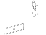
図1は、実施形態の運転支援装置が搭載される牽引車両10及び被牽引車両20の平面図である。牽引車両10は、トラクタとも呼ばれ、被牽引車両20を牽引して走行可能に構成されている。牽引車両10は、例えば、内燃機関(例えば、エンジン)及び電動機(例えば、モータ)等の駆動源を有する自動車(例えば、ハイブリッド自動車)であってよい。また、牽引車両10は、種々の変速装置を搭載することができるし、内燃機関及び電動機を駆動するのに必要な種々の装置を搭載することができる。また、牽引車両10における車輪13の駆動に関わる装置の方式、個数、及び、レイアウト等は、種々に設定することができる。
<First embodiment>
FIG. 1 is a plan view of a towed vehicle 10 and a towed vehicle 20 on which the driving support device of the embodiment is mounted. The towing vehicle 10 is also called a tractor, and is configured to be able to travel by towing the towed vehicle 20. The towing vehicle 10 may be, for example, a vehicle (for example, a hybrid vehicle) having a drive source such as an internal combustion engine (for example, an engine) and an electric motor (for example, a motor). Further, the towing vehicle 10 can be equipped with various transmissions, and can be equipped with various devices necessary for driving the internal combustion engine and the electric motor. In addition, the type, number, layout, and the like of the devices related to the driving of the wheels 13 in the towing vehicle 10 can be variously set.

図1に示すように、牽引車両10は、車体12と、4個の車輪13と、1または複数(本実施形態では4個)の撮像部14a、14b、14c、14dと、牽引装置18とを備える。撮像部14a、14b、14c、14dを区別する必要がない場合、撮像部14と記載する。   As shown in FIG. 1, the towing vehicle 10 includes a vehicle body 12, four wheels 13, one or more (four in the present embodiment) imaging units 14 a, 14 b, 14 c, 14 d, and a towing device 18. Is provided. When it is not necessary to distinguish the imaging units 14a, 14b, 14c, and 14d, they are referred to as the imaging unit 14.

車体12は、運転手を含む乗員が乗車する車室を構成する。車体12は、後述する運転支援装置とともに、車輪13、及び、撮像部14等を収容または保持する。   The vehicle body 12 forms a passenger compartment in which an occupant including a driver gets on. The vehicle body 12 accommodates or holds the wheels 13 and the imaging unit 14 together with a driving support device described later.

4個の車輪13は、車体12の前後左右に設けられている。例えば、前側の2個の車輪13は、転舵輪として機能して、後側の2個の車輪13は、駆動輪として機能する。   The four wheels 13 are provided on the front, rear, left and right of the vehicle body 12. For example, the two front wheels 13 function as steered wheels, and the two rear wheels 13 function as drive wheels.

撮像部14は、例えば、CCD(Charge Coupled Device)、または、CIS(CMOS Image Sensor)等の撮像素子を内蔵するデジタルカメラである。撮像部14は、所定のフレームレートで生成される複数のフレーム画像を含む動画、または、静止画のデータを撮像画像のデータとして出力する。撮像部14は、それぞれ、広角レンズまたは魚眼レンズを有し、水平方向の140°〜190°の範囲を撮影することができる。撮像部14の光軸は、斜め下方に向けて設定されている。従って、撮像部14は、路面を含む牽引車両10の周辺を撮像した撮像画像のデータを出力する。   The imaging unit 14 is a digital camera having a built-in imaging device such as a charge coupled device (CCD) or a CMOS image sensor (CIS). The imaging unit 14 outputs moving image or still image data including a plurality of frame images generated at a predetermined frame rate as captured image data. Each of the imaging units 14 has a wide-angle lens or a fisheye lens, and can capture an image in a horizontal range of 140 ° to 190 °. The optical axis of the imaging unit 14 is set obliquely downward. Therefore, the imaging unit 14 outputs data of a captured image of the periphery of the towing vehicle 10 including the road surface.

撮像部14は、車体12の周囲に設けられている。例えば、撮像部14aは、車体12の前端部の左右方向の中央部(例えば、フロントバンパー)に設けられている。撮像部14aは、牽引車両10の前方の周辺を撮像した撮像画像を生成する。撮像部14bは、車体12の後端部の左右方向の中央部(例えば、リアバンパー)に設けられている。撮像部14bは、牽引車両10の後方の周辺を撮像した撮像画像を生成する。具体的には、撮像部14bは、被牽引車両20を連結する連結部材26を含む撮像画像を生成する。撮像部14cは、車体12の左端部の前後方向の中央部(例えば、左側のサイドミラー12a)に設けられている。撮像部14cは、牽引車両10の左方の周辺を撮像した撮像画像を生成する。撮像部14dは、車体12の右端部の前後方向の中央部(例えば、右側のサイドミラー12b)に設けられている。撮像部14dは、牽引車両10の右方の周辺を撮像した撮像画像を生成する。   The imaging unit 14 is provided around the vehicle body 12. For example, the imaging unit 14a is provided at a center (for example, a front bumper) of the front end of the vehicle body 12 in the left-right direction. The imaging unit 14a generates a captured image obtained by capturing an image of an area in front of the towing vehicle 10. The imaging unit 14b is provided at the center of the rear end of the vehicle body 12 in the left-right direction (for example, a rear bumper). The imaging unit 14b generates a captured image that captures the surrounding area behind the towing vehicle 10. Specifically, the imaging unit 14b generates a captured image including the connecting member 26 that connects the towed vehicle 20. The imaging unit 14c is provided at the center of the left end of the vehicle body 12 in the front-rear direction (for example, the left side mirror 12a). The imaging unit 14c generates a captured image of the periphery of the towing vehicle 10 on the left. The imaging unit 14d is provided at the center in the front-rear direction of the right end of the vehicle body 12 (for example, the right side mirror 12b). The imaging unit 14d generates a captured image obtained by imaging the right periphery of the towing vehicle 10.

牽引装置18は、ヒッチともいわれる装置である。牽引装置18は、車体12の左右方向の中央部に設けられている。牽引装置18は、車体12の後端部から後方に突出している。牽引装置18は、例えば、鉛直方向に立設された柱状部材の上端部に設けられた球状のヒッチボール18aを有する。   The traction device 18 is a device also called a hitch. The traction device 18 is provided at the center of the vehicle body 12 in the left-right direction. The traction device 18 protrudes rearward from the rear end of the vehicle body 12. The traction device 18 has, for example, a spherical hitch ball 18a provided at the upper end of a columnar member that stands upright in the vertical direction.

被牽引車両20は、トレーラとも呼ばれ、牽引車両10に牽引されて走行する。被牽引車両20は、本体22と、複数(本実施形態では2個)のトレーラ車輪24と、連結部材26と、カプラ28とを備える。   The towed vehicle 20 is also called a trailer, and runs while being towed by the towed vehicle 10. The towed vehicle 20 includes a main body 22, a plurality of (two in this embodiment) trailer wheels 24, a connecting member 26, and a coupler 28.

本体22は、例えば、直方体の箱型に形成されている。本体22は、内部に荷物等を積載可能に中空状に構成されている。尚、本体22は、板状のフラット型であってもよい。   The main body 22 is formed in, for example, a rectangular parallelepiped box shape. The main body 22 is formed in a hollow shape so that luggage and the like can be loaded therein. Note that the main body 22 may be a plate-shaped flat type.

トレーラ車輪24は、本体22の左右にそれぞれ設けられている。トレーラ車輪24は、例えば、従動輪である。トレーラ車輪24は、エンジン等の駆動源と連結された駆動輪、または、ステアリングホイール等によって左右方向に転舵可能な転舵輪であってもよい。   The trailer wheels 24 are provided on the left and right sides of the main body 22, respectively. The trailer wheel 24 is, for example, a driven wheel. The trailer wheel 24 may be a drive wheel connected to a drive source such as an engine, or a steered wheel that can be steered in the left-right direction by a steering wheel or the like.

連結部材26は、本体22の左右方向の中央部に設けられている。連結部材26は、本体22の前端部から前方へと延びる。   The connecting member 26 is provided at the center of the main body 22 in the left-right direction. The connecting member 26 extends forward from the front end of the main body 22.

カプラ28は、連結部材26の前端部に設けられている。カプラ28には、ヒッチボール18aを覆う球状の凹部が形成されている。カプラ28がヒッチボール18aを覆うことによって、被牽引車両20は牽引車両10に対して旋回可能に連結される。本実施形態では、連結部材26の連結中心軸Nと、牽引車両10の車両中心軸Mと、からなる角度を、ヒッチ角度θとする。尚、ヒッチ角度θは、撮像部24bが撮像した撮像画像データから検出できるものとして、説明を省力する。   The coupler 28 is provided at a front end of the connecting member 26. The coupler 28 has a spherical concave portion that covers the hitch ball 18a. When the coupler 28 covers the hitch ball 18a, the towed vehicle 20 is turnably connected to the towed vehicle 10. In the present embodiment, an angle formed by the connection center axis N of the connection member 26 and the vehicle center axis M of the towing vehicle 10 is defined as a hitch angle θ. The hitch angle θ can be detected from the image data captured by the image capturing unit 24b, and the description is omitted.

図2は、実施形態の牽引車両10の車室内のダッシュボード近傍の図である。図2に例示されるように、牽引車両10は、操舵部30と、変速部31と、加速部32と、制動部33と、モニタ装置36とを更に備える。   FIG. 2 is a view near the dashboard in the cabin of the towing vehicle 10 of the embodiment. As illustrated in FIG. 2, the towing vehicle 10 further includes a steering unit 30, a transmission unit 31, an acceleration unit 32, a braking unit 33, and a monitoring device 36.

操舵部30は、前側の車輪13を転舵させて牽引車両10の左右の進行方向を変更させるために運転手が操作する装置である。操舵部30は、例えば、センターコンソールから突出して、運転席の前方に設けられたステアリングホイールまたはハンドルである。   The steering section 30 is a device operated by a driver to steer the front wheels 13 to change the left and right traveling directions of the towing vehicle 10. The steering unit 30 is, for example, a steering wheel or a steering wheel protruding from the center console and provided in front of the driver's seat.

変速部31は、例えば、センターコンソールから突出したシフトレバー等を含み、牽引車両10の変速比または牽引車両10の前後の進行方向(ドライブ、パーキング、及び、リバース等)を変更させる装置である。   The transmission unit 31 includes, for example, a shift lever projecting from the center console, and is a device that changes the speed ratio of the towing vehicle 10 or the traveling direction (drive, parking, reverse, etc.) of the towing vehicle 10 before and after.

加速部32は、牽引車両10を加速させるために運転手が操作する装置である。加速部32は、例えば、運転手の足下に設置されたアクセルペダルである。加速部32は、加速に関する操作を運転手から受け付けて、牽引車両10を加速させる。   The acceleration unit 32 is a device operated by a driver to accelerate the towing vehicle 10. The acceleration unit 32 is, for example, an accelerator pedal installed below the driver's feet. The acceleration unit 32 receives an operation related to acceleration from the driver and accelerates the towing vehicle 10.

制動部33は、牽引車両10を減速させるために運転手が操作する装置である。制動部33は、例えば、運転手の足下に設置されたブレーキペダルである。制動部33は、減速に関する操作を運転手から受け付けて、牽引車両10を減速させる。   The braking unit 33 is a device operated by a driver to decelerate the towing vehicle 10. The braking unit 33 is, for example, a brake pedal installed under the driver's feet. The braking unit 33 receives an operation related to deceleration from the driver, and decelerates the towing vehicle 10.

モニタ装置36は、牽引車両10の車室内のダッシュボード等に設けられている。モニタ装置36は、表示部38と、音声出力部40と、操作入力部42とを有する。   The monitor device 36 is provided on a dashboard or the like in the cabin of the towing vehicle 10. The monitor device 36 has a display unit 38, an audio output unit 40, and an operation input unit 42.

表示部38は、例えば、液晶ディスプレイ(LCD:Liquid Crystal Display)、または、有機ELディプレイ(OELD:Organic Electroluminescent Display)等の表示装置である。表示部38は、ナビゲーションシステムの道案内等の画像、及び、運転支援用の表示画像を表示する。   The display unit 38 is a display device such as a liquid crystal display (LCD: Liquid Crystal Display) or an organic EL display (OELD: Organic Electroluminescent Display). The display unit 38 displays an image such as a route guide of the navigation system and a display image for driving assistance.

音声出力部40は、例えば、スピーカである。音声出力部40は、ナビゲーションにおける運転手を案内する音声等を出力する。   The audio output unit 40 is, for example, a speaker. The voice output unit 40 outputs a voice or the like for guiding a driver in navigation.

操作入力部42は、乗員の入力を受け付ける。操作入力部42は、例えば、タッチパネルである。操作入力部42は、表示部38の表示画面に設けられている。操作入力部42は、表示部38が表示する画像を透過可能に構成されている。これにより、操作入力部42は、表示部38の表示画面に表示される画像を乗員に視認させることができる。操作入力部42は、表示部38の表示画面に表示される画像に対応した位置を乗員が触れることによって入力した指示を受け付ける。例えば、操作入力部42は、運転支援において牽引車両10の目標駐車位置及び目標駐車位置における牽引車両10の向きである目標駐車方向の入力を乗員から受け付ける。尚、操作入力部42は、タッチパネルに限らず、押しボタン式等のハードスイッチであってもよい。   The operation input unit 42 receives an occupant input. The operation input unit 42 is, for example, a touch panel. The operation input unit 42 is provided on a display screen of the display unit 38. The operation input unit 42 is configured to be able to transmit an image displayed by the display unit 38. Thereby, the operation input unit 42 can allow the occupant to visually recognize the image displayed on the display screen of the display unit 38. The operation input unit 42 receives an instruction input by the occupant touching a position corresponding to an image displayed on the display screen of the display unit 38. For example, the operation input unit 42 receives an input of a target parking position of the towing vehicle 10 and a target parking direction which is the direction of the towing vehicle 10 at the target parking position in driving assistance from the occupant. The operation input unit 42 is not limited to a touch panel, and may be a push button type or other hardware switch.

図3は、実施形態の運転支援装置60を含む運転支援システム50の全体構成を示すブロック図である。運転支援装置60は、牽引車両10に搭載されて、牽引車両10の周辺の画像(以下、周辺画像)と、当該周辺を上方の仮想視点から見た画像(以下、俯瞰画像)を含み目標駐車位置及び目標駐車方向を設定するための設定画像と、を含む表示画像を表示部38に表示させる。運転支援装置60は、乗員が設定画像上で設定した目標駐車位置及び目標駐車方向に基づいて、被牽引車両20を牽引する牽引車両10の運転を支援する。例えば、運転支援装置60は、左右方向において目標駐車位置と反対側に被牽引車両20を牽引する牽引車両10を前進させた後、目標駐車位置側に牽引車両10を前進させる。この後、運転支援装置60は、牽引車両10を後退させて、目標駐車位置に目標駐車方向で駐車させる。   FIG. 3 is a block diagram illustrating the overall configuration of the driving support system 50 including the driving support device 60 according to the embodiment. The driving support device 60 is mounted on the towing vehicle 10 and includes an image of the surroundings of the towing vehicle 10 (hereinafter, peripheral image) and an image of the surroundings as viewed from an upper virtual viewpoint (hereinafter, overhead image). A display image including a setting image for setting the position and the target parking direction is displayed on the display unit 38. The driving assistance device 60 assists the driving of the towing vehicle 10 towing the towed vehicle 20 based on the target parking position and the target parking direction set on the setting image by the occupant. For example, the driving support device 60 advances the towing vehicle 10 that pulls the towed vehicle 20 to the side opposite to the target parking position in the left-right direction, and then advances the towing vehicle 10 to the target parking position side. Thereafter, the driving support device 60 causes the towing vehicle 10 to retreat and park at the target parking position in the target parking direction.

図3に示すように、運転支援システム50は、複数の撮像部14a、14b、14c、14dと、操舵システム44と、加速システム45と、制動システム46と、変速システム47と、車速センサ59と、モニタ装置36と、運転支援装置60と、車内ネットワーク61とを備える。   As shown in FIG. 3, the driving support system 50 includes a plurality of imaging units 14a, 14b, 14c, and 14d, a steering system 44, an acceleration system 45, a braking system 46, a transmission system 47, a vehicle speed sensor 59, , A monitor device 36, a driving support device 60, and an in-vehicle network 61.

複数の撮像部14は、牽引車両10及び被牽引車両20の周辺を撮像した撮像画像を運転支援装置60へ出力する。   The plurality of imaging units 14 output captured images of the periphery of the towing vehicle 10 and the towed vehicle 20 to the driving support device 60.

操舵システム44は、牽引車両10の左右の進行方向を制御する。操舵システム44は、操舵部30と、操舵制御部51と、操舵部センサ52とを有する。   The steering system 44 controls the left and right traveling directions of the towing vehicle 10. The steering system 44 includes a steering unit 30, a steering control unit 51, and a steering unit sensor 52.

操舵制御部51は、例えば、CPU(Central Processing Unit)等のハードウェアプロセッサを有するECU(Electronic Control Unit)等のマイクロコンピュータを含むコンピュータである。操舵制御部51は、運転支援装置60からの指示に基づいて、操舵部30を制御して、牽引車両10の進行方向を制御する。   The steering control unit 51 is a computer including a microcomputer such as an ECU (Electronic Control Unit) having a hardware processor such as a CPU (Central Processing Unit). The steering control unit 51 controls the steering unit 30 based on an instruction from the driving support device 60 to control the traveling direction of the towing vehicle 10.

操舵部センサ52は、例えば、ホール素子等を含む角度センサであって、操舵部30の回転角である操舵角を検出する。操舵部センサ52は、検出した操舵部30の操舵角を車内ネットワーク61に出力する。   The steering unit sensor 52 is, for example, an angle sensor including a Hall element and the like, and detects a steering angle that is a rotation angle of the steering unit 30. The steering unit sensor 52 outputs the detected steering angle of the steering unit 30 to the in-vehicle network 61.

加速システム45は、牽引車両10の加速を制御する。加速システム45は、加速部32と、加速制御部53と、加速部センサ54とを有する。   The acceleration system 45 controls the acceleration of the towing vehicle 10. The acceleration system 45 includes an acceleration unit 32, an acceleration control unit 53, and an acceleration unit sensor 54.

加速制御部53は、例えば、CPU等のハードウェアプロセッサを有するECU等のマイクロコンピュータを含むコンピュータである。加速制御部53は、運転支援装置60からの指示に基づいて、加速部32を制御して、牽引車両10の加速を制御する。   The acceleration control unit 53 is, for example, a computer including a microcomputer such as an ECU having a hardware processor such as a CPU. The acceleration control unit 53 controls the acceleration unit 32 based on an instruction from the driving support device 60 to control the acceleration of the towing vehicle 10.

加速部センサ54は、例えば、位置センサであって、加速部32がアクセルペダルの場合、加速部32の位置を検出する。加速部センサ54は、検出した加速部32の位置を車内ネットワーク61に出力する。   The acceleration unit sensor 54 is, for example, a position sensor, and detects the position of the acceleration unit 32 when the acceleration unit 32 is an accelerator pedal. The acceleration unit sensor 54 outputs the detected position of the acceleration unit 32 to the in-vehicle network 61.

制動システム46は、牽引車両10の減速を制御する。制動システム46は、制動部33と、制動制御部55と、制動部センサ56とを有する。   The braking system 46 controls the deceleration of the towing vehicle 10. The braking system 46 includes a braking unit 33, a braking control unit 55, and a braking unit sensor 56.

制動制御部55は、例えば、CPU等のハードウェアプロセッサを有するECU等のマイクロコンピュータを含むコンピュータである。制動制御部55は、運転支援装置60からの指示に基づいて、制動部33を制御して、牽引車両10の減速を制御する。   The braking control unit 55 is a computer including a microcomputer such as an ECU having a hardware processor such as a CPU, for example. The braking control unit 55 controls the braking unit 33 based on an instruction from the driving support device 60 to control the deceleration of the towing vehicle 10.

制動部センサ56は、例えば、位置センサであって、制動部33がブレーキペダルの場合、制動部33の位置を検出する。制動部センサ56は、検出した制動部33の位置を車内ネットワーク61に出力する。   The braking unit sensor 56 is, for example, a position sensor, and detects the position of the braking unit 33 when the braking unit 33 is a brake pedal. The braking unit sensor 56 outputs the detected position of the braking unit 33 to the in-vehicle network 61.

変速システム47は、牽引車両10の変速比を制御する。変速システム47は、変速部31と、変速制御部57と、変速部センサ58とを有する。   The transmission system 47 controls the transmission ratio of the towing vehicle 10. The transmission system 47 includes a transmission unit 31, a transmission control unit 57, and a transmission unit sensor 58.

変速制御部57は、例えば、CPU等のハードウェアプロセッサを有するECU等のマイクロコンピュータを含むコンピュータである。変速制御部57は、運転支援装置60からの指示に基づいて、変速部31を制御して、牽引車両10の変速比を制御する。   The shift control unit 57 is a computer including a microcomputer such as an ECU having a hardware processor such as a CPU, for example. The transmission control unit 57 controls the transmission unit 31 based on an instruction from the driving support device 60 to control the transmission ratio of the towing vehicle 10.

変速部センサ58は、例えば、位置センサであって、変速部31がシフトレバーの場合、変速部31の位置を検出する。変速部センサ58は、検出した変速部31の位置を車内ネットワーク61に出力する。   The transmission unit sensor 58 is, for example, a position sensor, and detects the position of the transmission unit 31 when the transmission unit 31 is a shift lever. The transmission sensor 58 outputs the detected position of the transmission 31 to the in-vehicle network 61.

車速センサ59は、例えば、牽引車両10の速度である車速を算出するための車速情報を検出する。車速センサ59は、例えば、変速機の出力軸の回転数を車速情報として検出する。尚、車速センサ59は、車輪13の回転数、エンジン等の駆動部の出力軸の回転数等を車速情報として検出してもよい。車速センサ59は、検出した車速情報を車内ネットワーク61へ出力する。   The vehicle speed sensor 59 detects, for example, vehicle speed information for calculating a vehicle speed that is the speed of the towing vehicle 10. The vehicle speed sensor 59 detects, for example, the rotation speed of the output shaft of the transmission as vehicle speed information. The vehicle speed sensor 59 may detect the number of rotations of the wheels 13, the number of rotations of an output shaft of a drive unit such as an engine, or the like as vehicle speed information. The vehicle speed sensor 59 outputs the detected vehicle speed information to the in-vehicle network 61.

運転支援装置60は、ECU等のマイクロコンピュータを含むコンピュータである。運転支援装置60は、CPU60aと、ROM(Read Only Memory)60bと、RAM(Random Access Memory)60cと、表示制御部60dと、音声制御部60eと、SSD(Solid State Drive)60fとを備える。CPU60a、ROM60b及びRAM60cは、同一パッケージ内に集積されていてもよい。   The driving support device 60 is a computer including a microcomputer such as an ECU. The driving support device 60 includes a CPU 60a, a ROM (Read Only Memory) 60b, a RAM (Random Access Memory) 60c, a display control unit 60d, a voice control unit 60e, and an SSD (Solid State Drive) 60f. The CPU 60a, the ROM 60b, and the RAM 60c may be integrated in the same package.

CPU60aは、ハードウェアプロセッサの一例であって、ROM60b等の不揮発性の記憶装置に記憶されたプログラムを読み出して、当該プログラムにしたがって各種の演算処理および制御を実行する。CPU60aは、例えば、牽引車両10の運転支援の処理を実行する。   The CPU 60a is an example of a hardware processor, reads a program stored in a non-volatile storage device such as the ROM 60b, and executes various arithmetic processes and controls according to the program. The CPU 60a executes, for example, a process of driving assistance of the towing vehicle 10.

ROM60bは、各プログラム及びプログラムの実行に必要なパラメータ等を記憶する。RAM60cは、CPU60aでの演算で用いられる各種のデータを一時的に記憶する。表示制御部60dは、運転支援装置60での演算処理のうち、主として、撮像部14から得られた撮像画像の画像処理、表示部38に表示させる表示用の画像のデータ変換等を実行して、画像情報を表示部38へ出力する。音声制御部60eは、運転支援装置60での演算処理のうち、主として、音声出力部40に出力させる音声の処理を実行して、音声データを音声出力部40へ出力する。SSD60fは、書き換え可能な不揮発性の記憶装置であって、運転支援装置60の電源がオフされた場合にあってもデータを維持する。   The ROM 60b stores each program, parameters necessary for executing the program, and the like. The RAM 60c temporarily stores various data used in the calculation by the CPU 60a. The display control unit 60d mainly performs image processing of a captured image obtained from the imaging unit 14, data conversion of a display image to be displayed on the display unit 38, and the like in the arithmetic processing in the driving support device 60. , And outputs the image information to the display unit 38. The voice control unit 60e mainly executes a process of a voice to be output to the voice output unit 40 among arithmetic processing in the driving support device 60, and outputs voice data to the voice output unit 40. The SSD 60f is a rewritable nonvolatile storage device, and retains data even when the power of the driving support device 60 is turned off.

車内ネットワーク61は、例えば、CAN(Controller Area Network)及びLIN(Local Interconnect Network)等を含む。車内ネットワーク61は、センサ52、54、56、58、59と、制御部51、53、55、57と、モニタ装置36の操作入力部42と、運転支援装置60とを互いに情報を送受信可能に接続する。   The in-vehicle network 61 includes, for example, a CAN (Controller Area Network) and a LIN (Local Interconnect Network). The in-vehicle network 61 enables the sensors 52, 54, 56, 58, 59, the control units 51, 53, 55, 57, the operation input unit 42 of the monitor device 36, and the driving support device 60 to transmit and receive information to and from each other. Connecting.

図4は、運転支援装置60の機能を説明する機能ブロック図である。図4に示すように、運転支援装置60は、処理部62及び記憶部64の機能を有する。   FIG. 4 is a functional block diagram illustrating functions of the driving support device 60. As shown in FIG. 4, the driving support device 60 has functions of a processing unit 62 and a storage unit 64.

処理部62は、CPU60aの機能として実現される。処理部62は、ハードウェアとソフトウェア(運転支援プログラム72)が協働することにより、運転支援装置60としての機能の少なくとも一部を実現している。処理部62は、設定部66及び支援部68の機能を有する。処理部62は、記憶部64に格納された運転支援プログラム72を読み込むことによって、設定部66及び支援部68の機能を実現してよい。尚、設定部66及び支援部68の一部または全部は、ASIC(Application Specific Integrated Circuit)及びFPGA(Field-Programmable Gate Array)を含む回路等のハードウェアによって構成してもよい。   The processing unit 62 is realized as a function of the CPU 60a. The processing unit 62 realizes at least a part of the function as the driving support device 60 by cooperation of hardware and software (the driving support program 72). The processing unit 62 has functions of a setting unit 66 and a support unit 68. The processing unit 62 may realize the functions of the setting unit 66 and the support unit 68 by reading the driving support program 72 stored in the storage unit 64. A part or all of the setting unit 66 and the support unit 68 may be configured by hardware such as a circuit including an ASIC (Application Specific Integrated Circuit) and an FPGA (Field-Programmable Gate Array).

設定部66は、牽引車両10及び被牽引車両20を駐車する目標駐車位置及び目標駐車方向を設定する。設定部66は、乗員からの指示に応じて、牽引車両10に対する予め定められた相対位置に目標駐車位置を設定してよい。設定部66は、目標駐車位置での牽引車両10の方向として目標駐車方向を設定してよい。例えば、設定部66は、表示部38に目標駐車位置を設定するための目標駐車枠を含む設定画像を表示させた状態で目標駐車枠の傾きを受け付けて、受け付けた当該傾きに基づいて目標駐車方向を設定してよい。具体的には、設定部66は、操舵部30の操舵に応じて目標駐車枠を設定画面上で回転させた目標駐車枠の傾きを目標駐車方向として設定してよい。設定部66は、操舵部センサ52から取得した操舵部30の操舵角に応じて目標駐車枠を回転させて傾けてよい。設定部66は、設定した目標駐車位置及び目標駐車方向を含む目標駐車情報を支援部68へ出力する。   The setting unit 66 sets a target parking position and a target parking direction for parking the towing vehicle 10 and the towed vehicle 20. The setting unit 66 may set the target parking position at a predetermined relative position with respect to the towing vehicle 10 according to an instruction from the occupant. The setting unit 66 may set the target parking direction as the direction of the towing vehicle 10 at the target parking position. For example, the setting unit 66 receives the inclination of the target parking frame in a state where a setting image including the target parking frame for setting the target parking position is displayed on the display unit 38, and performs the target parking based on the received inclination. The direction may be set. Specifically, the setting unit 66 may set the inclination of the target parking frame obtained by rotating the target parking frame on the setting screen in accordance with the steering of the steering unit 30 as the target parking direction. The setting unit 66 may rotate and tilt the target parking frame according to the steering angle of the steering unit 30 acquired from the steering unit sensor 52. The setting unit 66 outputs target parking information including the set target parking position and target parking direction to the support unit 68.

支援部68は、各センサ52、54、56、58、59から取得したセンサ値等に基づいて、各システム44、45、46、47を制御して、設定部66が出力した目標駐車情報に含まれる目標駐車位置及び目標駐車方向に基づいて牽引車両10及び被牽引車両20を駐車させる。具体的には、支援部68は、設定部66から目標駐車情報を取得すると、加速指示を加速制御部53に出力して加速部32を制御して牽引車両10を前進させる。支援部68は、牽引車両10の前進中に、操舵部30を制御する。具体的には、支援部68は、前進中に、操舵角を示す操舵情報を操舵制御部51に出力して、目標駐車位置とは反対側に操舵部30を操舵させた後、目標駐車位置側に操舵部30を操舵させる。支援部68は、牽引車両10と目標駐車位置との距離及び方向等に基づいて、操舵部30の操舵を目標駐車位置の反対側から目標駐車位置側へと転換してよい。支援部68は、牽引車両10と被牽引車両20との間の連結状態が目標駐車位置方向側に傾いた後に、牽引車両10を停止させるための停止情報を出力してよい。例えば、支援部68は、ヒッチ角度に応じて、停止情報を出力して、牽引車両10を前進から後退へと切り替えてよい。また、支援部68は、被牽引車両20の後端部が、被牽引車両20の左右方向側に存在する目標駐車位置より進んだ後に牽引車両10を停止させるための停止情報を出力して、牽引車両10を停止させてもよい。具体的には、支援部68は、ヒッチ角度が予め定められた判定角度になると、制動部33及び加速部32を制御して、牽引車両10を停止させる。支援部68は、撮像部14bの撮像画像から算出したヒッチ角度に基づいて、ヒッチ角度が判定角度になったか否かを判定してよい。支援部68は、加速部32及び変速部31を制御して、停止させた牽引車両10を後退させる。支援部68は、操舵部30を操舵して牽引車両10及び被牽引車両20を目標駐車位置に目標駐車方向で駐車させる。本実施形態では、ヒッチ角度に基づいて目標駐車位置に駐車可能と判断された場合に、牽引車両10を停止できればどのような判断手法を用いてもよい。例えば、支援部68は、2段階目の操舵を行った後であって、現在のヒッチ角度、及び牽引車両10及び被牽引車両20の現在の位置に基づいて、中立ステアまたは所定の逆ステアで後退した場合の移動軌跡を常時計算し、目標駐車位置に停車可能と判断した時点で、牽引車両10を停止させる等が考えられる。このように、本実施形態の支援部68は、牽引車両10の前進中に、目標駐車位置の反対側に操舵部30を操舵させた後、目標駐車位置側に操舵部30を操舵させるという、2段階操舵を行った後に、牽引車両10を停止させるための制御を行うこととした。1段階目の目標駐車位置の反対側への操舵で、目標駐車位置からある程度離れた状態にするとともに、2段階目の目標駐車位置側への操舵で、牽引車両10に対して被牽引車両20を目標駐車位置側に傾いた姿勢することができる。これにより、本実施形態は、牽引車両10及び被牽引車両20に対して、目標駐車位置に駐車可能な位置までの移動と、駐車可能な姿勢の確保とを実現できる。   The support unit 68 controls the systems 44, 45, 46, 47 based on the sensor values and the like acquired from the sensors 52, 54, 56, 58, 59, and outputs the target parking information output by the setting unit 66. The towing vehicle 10 and the towed vehicle 20 are parked based on the included target parking position and target parking direction. Specifically, when acquiring the target parking information from the setting unit 66, the support unit 68 outputs an acceleration instruction to the acceleration control unit 53, controls the acceleration unit 32, and advances the towing vehicle 10. The support unit 68 controls the steering unit 30 while the towing vehicle 10 is moving forward. Specifically, the assisting unit 68 outputs the steering information indicating the steering angle to the steering control unit 51 during the forward movement, causes the steering unit 30 to be steered to the opposite side to the target parking position, and then outputs the target parking position. The steering unit 30 is steered to the side. The support unit 68 may change the steering of the steering unit 30 from the opposite side of the target parking position to the target parking position based on the distance and direction between the towing vehicle 10 and the target parking position. The support unit 68 may output stop information for stopping the towing vehicle 10 after the connection state between the towing vehicle 10 and the towed vehicle 20 is inclined toward the target parking position. For example, the support unit 68 may output stop information according to the hitch angle, and switch the towing vehicle 10 from forward to backward. In addition, the support unit 68 outputs stop information for stopping the towed vehicle 10 after the rear end of the towed vehicle 20 has advanced beyond the target parking position existing on the left and right sides of the towed vehicle 20, The towing vehicle 10 may be stopped. Specifically, when the hitch angle reaches a predetermined determination angle, the support unit 68 controls the braking unit 33 and the acceleration unit 32 to stop the towing vehicle 10. The support unit 68 may determine whether or not the hitch angle has reached the determination angle based on the hitch angle calculated from the image captured by the image capturing unit 14b. The support unit 68 controls the acceleration unit 32 and the transmission unit 31 to move the stopped towing vehicle 10 backward. The support unit 68 steers the steering unit 30 to park the towing vehicle 10 and the towed vehicle 20 at the target parking position in the target parking direction. In the present embodiment, when it is determined that parking at the target parking position is possible based on the hitch angle, any determination method may be used as long as the towing vehicle 10 can be stopped. For example, after performing the second-stage steering, the support unit 68 performs neutral steering or predetermined reverse steering based on the current hitch angle and the current positions of the towing vehicle 10 and the towed vehicle 20. It is conceivable to constantly calculate the movement trajectory when the vehicle retreats and stop the towing vehicle 10 when it is determined that the vehicle can be stopped at the target parking position. As described above, the support unit 68 of the present embodiment causes the steering unit 30 to be steered to the target parking position side after the steering unit 30 is steered to the opposite side of the target parking position while the towing vehicle 10 is moving forward. After performing the two-stage steering, control for stopping the towing vehicle 10 is performed. Steering to the opposite side of the target parking position in the first stage brings the vehicle away from the target parking position to some extent, and steering to the target parking position in the second stage causes the towed vehicle 20 to move relative to the towed vehicle 10. Can be tilted toward the target parking position. Accordingly, in the present embodiment, it is possible to realize the movement of the towing vehicle 10 and the towed vehicle 20 to a position where the vehicle can be parked at the target parking position, and secure a parking-possible posture.

記憶部64は、例えば、ROM60b、RAM60c及びSSD60fの少なくともいずれかの機能として実現される。記憶部64は、処理部62と情報を入出力可能に接続されている。記憶部64は、ネットワーク等を介して接続された外部の記憶装置であってもよい。記憶部64は、処理部62が実行するプログラム及びプログラムの実行に必要なデータ等を記憶する。例えば、記憶部64は、処理部62が実行する運転支援プログラム72を記憶する。尚、運転支援プログラム72は、CD−ROM(Compact Disc Read Only Memory)またはDVD−ROM(Digital Versatile Disc Read Only Memory)等のコンピュータにより読み取り可能な記憶媒体に記憶されて提供されてもよく、インターネット等のネットワークを介して提供されてもよい。記憶部64は、運転支援プログラム72の実行に必要な数値データ74を記憶する。数値データ74は、判定角度等を含んでよい。記憶部64は、撮像画像等の画像データ、及び、目標駐車情報等を一時的に記憶する。   The storage unit 64 is realized, for example, as at least one of the functions of the ROM 60b, the RAM 60c, and the SSD 60f. The storage unit 64 is connected to the processing unit 62 so that information can be input and output. The storage unit 64 may be an external storage device connected via a network or the like. The storage unit 64 stores a program executed by the processing unit 62, data necessary for executing the program, and the like. For example, the storage unit 64 stores a driving support program 72 executed by the processing unit 62. The driving support program 72 may be provided by being stored in a computer-readable storage medium such as a CD-ROM (Compact Disc Read Only Memory) or a DVD-ROM (Digital Versatile Disc Read Only Memory). Etc. may be provided via a network. The storage unit 64 stores numerical data 74 necessary for executing the driving support program 72. The numerical data 74 may include a determination angle and the like. The storage unit 64 temporarily stores image data such as a captured image, target parking information, and the like.

図5は、第1実施形態における目標駐車方向を設定する設定画像84を含む表示画像80の一例を示す図である。図5に示すように、設定部66は、周辺画像82及び設定画像84を含む表示画像80を表示部38に表示させて、目標駐車位置及び目標駐車方向の入力を受け付ける。設定部66は、表示画像80内において、周辺画像82を右側、設定画像84を左側に配置する。尚、周辺画像82及び設定画像84の配置は適宜変更してよい。   FIG. 5 is a diagram illustrating an example of the display image 80 including the setting image 84 for setting the target parking direction in the first embodiment. As shown in FIG. 5, the setting unit 66 displays a display image 80 including the peripheral image 82 and the setting image 84 on the display unit 38, and receives an input of the target parking position and the target parking direction. The setting unit 66 arranges the peripheral image 82 on the right side and the setting image 84 on the left side in the display image 80. Note that the arrangement of the peripheral image 82 and the setting image 84 may be changed as appropriate.

設定部66は、例えば、牽引車両10の後部に設置された撮像部14bの撮像画像を周辺画像82として表示部38に表示させる。尚、設定部66は、他の撮像部14の撮像画像を周辺画像82として表示部38に表示させてもよい。例えば、設定部66は、目標駐車位置側の撮像部14の撮像画像を周辺画像82として採用してもよい。設定部66は、目標駐車方向を設定するモードである奥行線回転モードの指示を受け付ける奥行線回転モードボタン86aを周辺画像82に重畳させてよい。   The setting unit 66 causes the display unit 38 to display a captured image of the imaging unit 14b installed at the rear of the towing vehicle 10 as a peripheral image 82, for example. The setting unit 66 may cause the display unit 38 to display a captured image of another imaging unit 14 as the peripheral image 82. For example, the setting unit 66 may adopt a captured image of the imaging unit 14 on the target parking position side as the peripheral image 82. The setting unit 66 may superimpose a depth line rotation mode button 86a for receiving an instruction of the depth line rotation mode, which is a mode for setting the target parking direction, on the peripheral image 82.

設定部66は、例えば、牽引車両10の前後左右に設けられた4個の撮像部14の撮像画像から生成した俯瞰画像を含む設定画像84を表示部38に表示させる。設定部66は、牽引車両10及び被牽引車両20の位置を示す車両画像88a及び車両画像88bを設定画像84に重畳させてよい。設定部66は、基準点90aを含む目標駐車枠90を設定画像84に重畳させてよい。設定部66は、左右方向における目標駐車枠90の位置(ここでは、左側)を、例えば、乗員からの入力に応じて設定してよい。目標駐車枠90は、一対の方向線90bと、一対の奥行線90cとを含む。一対の方向線90bは、牽引車両10の進行方向に沿って延び、互いに牽引車両10の車幅程度の間隔を空けて配置されている。一対の奥行線90cは、対応する方向線90bの内側の端点から目標駐車枠90の奥(ここでは、左側)へと延び、互いに平行かつ対向する。奥行線90cは、方向線90bと交差(例えば、直交)してよい。設定部66は、牽引車両10の車両画像88aから予め定められた位置に目標駐車枠90を配置してよい。設定画像84の俯瞰画像は、駐車場の駐車枠92を区画するために路面上に設けられた区画線94を含む。区画線94の奥行線は、駐車場の通路に沿って傾斜している。具体的には、区画線94の奥行線は、入口側が奥側よりも牽引車両10の進行方向側に配置されている。   The setting unit 66 causes the display unit 38 to display a setting image 84 including a bird's-eye view image generated from the captured images of the four imaging units 14 provided on the front, rear, left, and right of the towing vehicle 10, for example. The setting unit 66 may superimpose the vehicle image 88a and the vehicle image 88b indicating the positions of the towing vehicle 10 and the towed vehicle 20 on the setting image 84. The setting unit 66 may superimpose the target parking frame 90 including the reference point 90a on the setting image 84. The setting unit 66 may set the position (here, the left side) of the target parking frame 90 in the left-right direction, for example, according to an input from an occupant. The target parking frame 90 includes a pair of direction lines 90b and a pair of depth lines 90c. The pair of direction lines 90b extend along the traveling direction of the towing vehicle 10 and are arranged with an interval of about the vehicle width of the towing vehicle 10 therebetween. The pair of depth lines 90c extend from the inner end point of the corresponding direction line 90b to the depth (here, left side) of the target parking frame 90, and are parallel and opposed to each other. The depth line 90c may intersect (eg, be orthogonal to) the direction line 90b. The setting unit 66 may arrange the target parking frame 90 at a predetermined position from the vehicle image 88a of the towing vehicle 10. The bird's-eye view image of the setting image 84 includes a partition line 94 provided on the road surface to partition the parking frame 92 of the parking lot. The depth line of the division line 94 is inclined along the passage of the parking lot. Specifically, the depth line of the division line 94 is arranged such that the entrance side is closer to the traveling direction of the towing vehicle 10 than the depth side.

図6は、目標駐車位置が設定された状態での設定画像84を含む表示画像80の一例を示す図である。図6に示すように、牽引車両10が前進すると、設定部66は、設定画像84内の俯瞰画像を車両画像88a、88bに対して後退させる。運転手は、目標駐車枠90の基準点90aが区画線94の角と一致するように牽引車両10を移動させる。乗員は奥行線回転モードボタン86aをタッチによって操作すると、設定部66は、目標駐車枠90の基準点90aを設定画像84上で固定するとともに、目標駐車枠90の基準点90aに応じた目標駐車位置を設定するとともに、奥行線回転モードに移行する。   FIG. 6 is a diagram illustrating an example of the display image 80 including the setting image 84 in a state where the target parking position is set. As shown in FIG. 6, when the towing vehicle 10 moves forward, the setting unit 66 moves the bird's-eye view image in the setting image 84 backward with respect to the vehicle images 88a and 88b. The driver moves the towing vehicle 10 so that the reference point 90 a of the target parking frame 90 coincides with the corner of the lane marking 94. When the occupant operates the depth line rotation mode button 86a by touching, the setting unit 66 fixes the reference point 90a of the target parking frame 90 on the setting image 84 and sets the target parking position corresponding to the reference point 90a of the target parking frame 90. The position is set, and the mode shifts to the depth line rotation mode.

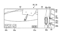
図7は、奥行線回転モードにおける目標駐車方向が設定された設定画像84を含む表示画像80の一例を示す図である。図7に示すように、奥行線回転モードでは、設定部66は、運転支援を指示するガイドボタン82aを周辺画像82に重畳させつつ、操舵部30の回転を受け付けて、奥行線90cを回転させる。具体的には、運転手が操舵部30を回転させると、設定部66は、操舵部センサ52から操舵部30の操舵角を取得する。設定部66は、操舵部30の操舵角に応じて、方向線90bは固定しつつ、一対の奥行線90cを回転させる。ここでいう操舵角は、例えば、奥行線回転モードに移行した時の操舵部30の位置を基準角度(即ち、0°)とし、当該基準角度からの回転角度である。設定部66は、一対の奥行線90cのそれぞれの一端部(ここで、方向線90b側の端部)をそれぞれの回転中心として、設定画像84上で奥行線90cを回転させる。ここで、設定部66は、操舵部30の回転方向等を示す操舵画像84aを設定画像84に重畳させてもよい。運転手は操舵部30の操舵に応じて回転する奥行線90cを見つつ、奥行線90cを区画線94に合わせて、ガイドボタン82aをタッチによって操作する。設定部66は、ガイドボタン82aの操作による支援指示を受け付けると、奥行線90cに応じた目標駐車方向を設定するとともに、目標駐車位置及び目標駐車方向を含む目標駐車情報を支援部68へ出力する。   FIG. 7 is a diagram illustrating an example of the display image 80 including the setting image 84 in which the target parking direction is set in the depth line rotation mode. As illustrated in FIG. 7, in the depth line rotation mode, the setting unit 66 receives the rotation of the steering unit 30 and rotates the depth line 90c while superimposing the guide button 82a for instructing driving assistance on the peripheral image 82. . Specifically, when the driver rotates the steering unit 30, the setting unit 66 acquires the steering angle of the steering unit 30 from the steering unit sensor 52. The setting unit 66 rotates the pair of depth lines 90c while fixing the direction line 90b according to the steering angle of the steering unit 30. The steering angle referred to here is, for example, the rotation angle from the reference angle, with the position of the steering section 30 at the time of shifting to the depth line rotation mode being the reference angle (ie, 0 °). The setting unit 66 rotates the depth line 90c on the setting image 84 with each end of the pair of depth lines 90c (here, the end on the direction line 90b side) as the center of rotation. Here, the setting unit 66 may superimpose the steering image 84a indicating the rotation direction and the like of the steering unit 30 on the setting image 84. The driver adjusts the depth line 90c to the division line 94 and operates the guide button 82a by touching while watching the depth line 90c that rotates in accordance with the steering of the steering unit 30. When receiving the support instruction by operating the guide button 82a, the setting unit 66 sets the target parking direction according to the depth line 90c and outputs the target parking information including the target parking position and the target parking direction to the support unit 68. .

図8は、支援部68による運転支援を説明する平面図である。図8に示すように、支援部68が支援指示を受け付けたときに、牽引車両10が、目標駐車位置及び目標駐車方向の対象である駐車枠92の区画線94の近傍に位置するとする。   FIG. 8 is a plan view illustrating driving support by the support unit 68. As shown in FIG. 8, it is assumed that when the support unit 68 receives a support instruction, the towing vehicle 10 is positioned near the division line 94 of the parking frame 92 that is the target of the target parking position and the target parking direction.

図9は、支援部68による最初の操舵における運転支援を説明する平面図である。図9に示すように、支援部68は、運転支援を開始すると、加速部32を制御して牽引車両10を前進させるとともに、操舵部30を目標駐車位置とは反対側(ここでは、右側)に操舵して、牽引車両10を目標駐車位置とは反対側に進行させる。   FIG. 9 is a plan view illustrating driving assistance in the first steering by the assistance unit 68. As shown in FIG. 9, when starting the driving support, the support unit 68 controls the acceleration unit 32 to move the towing vehicle 10 forward, and sets the steering unit 30 on the opposite side (here, the right side) from the target parking position. To move the towing vehicle 10 to the opposite side to the target parking position.

図10は、支援部68による2段階目の操舵における運転支援を説明する平面図である。図10に示すように、支援部68は、前進を継続させつつ、例えば目標駐車位置からの距離が予め定められた距離になると、操舵部30を目標駐車位置側へと操舵して、牽引車両10を目標駐車位置側へと進行させる。これにより、支援部68は、牽引車両10及び被牽引車両20を目標駐車位置の反対側に突出するように曲げることができる。支援部68は、ヒッチ角度が予め定められた判定角度になると、加速部32及び制動部33を制御して、牽引車両10を停止させる。図10における牽引車両10を停止させるヒッチ角度は、目標駐車方向に対応して定められる。換言すれば、本実施形態の支援部68は、設定部66により目標駐車方向が設定された場合に、目標駐車方向に対応した、ヒッチ角度となった場合に、牽引車両10を停止させるための停止情報を出力する。   FIG. 10 is a plan view illustrating driving assistance in the second-stage steering by the assistance unit 68. As illustrated in FIG. 10, when the distance from the target parking position reaches a predetermined distance, for example, the support unit 68 steers the steering unit 30 to the target parking position side while continuing to advance, and the towing vehicle 10 is advanced to the target parking position side. Accordingly, the support unit 68 can bend the towing vehicle 10 and the towed vehicle 20 so as to project to the opposite side of the target parking position. When the hitch angle reaches a predetermined determination angle, the support unit 68 controls the acceleration unit 32 and the braking unit 33 to stop the towing vehicle 10. The hitch angle for stopping the towing vehicle 10 in FIG. 10 is determined according to the target parking direction. In other words, the support unit 68 of the present embodiment is configured to stop the towing vehicle 10 when the target parking direction is set by the setting unit 66 and the hitch angle corresponding to the target parking direction is reached. Output stop information.

図11は、支援部68に後退による運転支援を説明する平面図である。図11に示すように、支援部68は、ヒッチ角度となった牽引車両10を停止させた後、加速部32及び変速部31を制御して後退させつつ、操舵部30を基準状態(いわゆる中立状態)または目標駐車位置側に操舵して、牽引車両10及び被牽引車両20を目標駐車位置及び目標駐車方向となるように目標とする駐車枠92へ誘導する。支援部68は、牽引車両10及び被牽引車両20が当該駐車枠92に達すると、加速部32及び制動部33を制御して牽引車両10を停止させる。   FIG. 11 is a plan view for explaining driving support by the retreat to the support unit 68. As illustrated in FIG. 11, after stopping the towing vehicle 10 at the hitch angle, the support unit 68 controls the acceleration unit 32 and the transmission unit 31 to retreat and sets the steering unit 30 in a reference state (a so-called neutral state). (State) or steering to the target parking position side to guide the towing vehicle 10 and the towed vehicle 20 to the target parking frame 92 so as to be in the target parking position and the target parking direction. When the towing vehicle 10 and the towed vehicle 20 reach the parking frame 92, the support unit 68 controls the acceleration unit 32 and the braking unit 33 to stop the towing vehicle 10.

図12は、運転支援装置60が実行する運転支援処理のフローチャートである。図12に示すように、運転支援処理では、設定部66が、設定処理を実行して、目標駐車位置及び目標駐車方向を設定し、当該目標駐車位置及び目標駐車方向を含む目標駐車情報を支援部68へ出力する(S102)。支援部68は、目標駐車情報を取得すると、支援処理を実行して、目標駐車位置で目標駐車方向になるように牽引車両10の運転を支援する(S104)。   FIG. 12 is a flowchart of a driving support process executed by the driving support device 60. As shown in FIG. 12, in the driving support process, the setting unit 66 executes the setting process to set the target parking position and the target parking direction, and supports the target parking information including the target parking position and the target parking direction. Output to the unit 68 (S102). When acquiring the target parking information, the support unit 68 executes a support process to support the driving of the towing vehicle 10 in the target parking direction in the target parking direction (S104).

図13は、設定部66が実行する第1実施形態の設定処理のフローチャートである。図13に示すように、第1実施形態の設定処理では、設定部66は、撮像部14から撮像画像を取得して(S202)、目標駐車枠90を含む設定画像84及び周辺画像82を含む図5に示すような表示画像80を表示部38に表示させる(S204)。この状態で、運転手は牽引車両10を移動させて、目標駐車枠90を路面の区画線94の角に合わせる。   FIG. 13 is a flowchart of the setting process of the first embodiment executed by the setting unit 66. As illustrated in FIG. 13, in the setting process of the first embodiment, the setting unit 66 acquires a captured image from the imaging unit 14 (S202), and includes a setting image 84 including the target parking frame 90 and a peripheral image 82. A display image 80 as shown in FIG. 5 is displayed on the display unit 38 (S204). In this state, the driver moves the towing vehicle 10 to adjust the target parking frame 90 to the corner of the lane marking 94 on the road surface.

設定部66は、乗員が奥行線回転モードを選択したか否かを判定する(S206)。設定部66は、乗員が奥行線回転モードを選択するまで(S206:No)、ステップS202以降を繰り返す。図6に示すように、運転手が目標駐車枠90を路面の区画線94の角に合わせて、奥行線回転モードボタン86aを操作すると、設定部66は、奥行線回転モードを選択したと判定して(S206:Yes)、乗員が操舵部30を操舵したか否かを判定する(S208)。尚、設定部66は、既に奥行線回転モードを選択済みの場合も、ステップS208を実行する。設定部66は、操舵部30が操舵されていないと判定すると(S208:No)、ステップS212を実行する。   The setting unit 66 determines whether or not the occupant has selected the depth line rotation mode (S206). The setting unit 66 repeats Step S202 and subsequent steps until the occupant selects the depth line rotation mode (S206: No). As shown in FIG. 6, when the driver operates the depth line rotation mode button 86a with the target parking frame 90 aligned with the corner of the lane marking 94 on the road surface, the setting unit 66 determines that the depth line rotation mode has been selected. Then (S206: Yes), it is determined whether or not the occupant has steered the steering unit 30 (S208). Note that the setting unit 66 also executes step S208 when the depth line rotation mode has already been selected. When the setting unit 66 determines that the steering unit 30 is not being steered (S208: No), the setting unit 66 executes step S212.

設定部66は、操舵部30が操舵されたと判定すると(S208:Yes)、図7に示すように、表示画像80上の目標駐車枠90の一対の奥行線90cを、奥行線90cの各一端部を回転中心として回転させる(S210)。設定部66は、支援指示を取得したか否かを判定する(S212)。設定部66は、支援指示を取得していないと判定すると(S212:No)、ステップS202以降を繰り返す。乗員がガイドボタン82aをタッチして操作すると、設定部66は、支援指示を取得したと判定して(S212:Yes)、目標駐車位置及び目標駐車方向を決定して、目標駐車位置及び目標駐車方向を含む目標駐車情報を支援部68へ出力する(S214)。これにより、設定部66は、設定処理を終了する。   If the setting unit 66 determines that the steering unit 30 has been steered (S208: Yes), as shown in FIG. 7, the pair of depth lines 90c of the target parking frame 90 on the display image 80 are displayed at one end of the depth line 90c. The part is rotated about the center of rotation (S210). The setting unit 66 determines whether a support instruction has been acquired (S212). If the setting unit 66 determines that the support instruction has not been acquired (S212: No), the setting unit 66 repeats step S202 and subsequent steps. When the occupant touches and operates the guide button 82a, the setting unit 66 determines that the support instruction has been acquired (S212: Yes), determines the target parking position and the target parking direction, and sets the target parking position and the target parking position. The target parking information including the direction is output to the support unit 68 (S214). Thus, the setting unit 66 ends the setting process.

図14は、支援部68が実行する第1実施形態の支援処理のフローチャートである。図14に示すように、支援部68は、設定部66から目標駐車情報を取得したか否かを判定する(S302)。支援部68は、目標駐車情報を取得するまで(S302:No)、待機状態となる。支援部68は、目標駐車情報を取得すると(S302:Yes)、図8に示す状態から加速制御部53を介して加速部32を制御して牽引車両10を前進させる(S304)。支援部68は、前進の開始に伴って、操舵角を示す操舵情報を操舵制御部51に出力することによって、目標駐車位置と反対側に操舵するように操舵部30を制御する(S306)。これにより、牽引車両10は、図9に示すように、目標駐車位置の反対側へと前進する。   FIG. 14 is a flowchart of the support processing of the first embodiment executed by the support unit 68. As shown in FIG. 14, the support unit 68 determines whether the target parking information has been acquired from the setting unit 66 (S302). The support unit 68 is in a standby state until the target parking information is obtained (S302: No). When acquiring the target parking information (S302: Yes), the support unit 68 controls the acceleration unit 32 via the acceleration control unit 53 to advance the towing vehicle 10 from the state shown in FIG. 8 (S304). The assisting unit 68 controls the steering unit 30 so as to steer to the opposite side to the target parking position by outputting steering information indicating the steering angle to the steering control unit 51 with the start of the forward movement (S306). This causes the towing vehicle 10 to move forward to the opposite side of the target parking position, as shown in FIG.

支援部68は、操舵方向を転換するか否かを判定する(S308)。支援部68は、操舵方向を転換すると判定するまで(S308:No)、前進及び同じ方向への操舵を継続する。支援部68は、目標駐車位置から牽引車両10までの距離に基づいて、操舵方向を転換すると判定すると(S308:Yes)、前進を継続させつつ、操舵角を示す操舵情報を操舵制御部51に出力することによって、図10に示すように、目標駐車位置側へと操舵部30を操舵する(S310)。   The support unit 68 determines whether to change the steering direction (S308). The support unit 68 continues the forward movement and the steering in the same direction until it is determined that the steering direction is changed (S308: No). When determining that the steering direction is to be changed based on the distance from the target parking position to the towing vehicle 10 (S308: Yes), the support unit 68 sends the steering information indicating the steering angle to the steering control unit 51 while continuing the forward movement. By outputting, as shown in FIG. 10, the steering unit 30 is steered toward the target parking position (S310).

支援部68は、ヒッチ角度が判定角度より大きいか否かを判定する(S312)。支援部68は、ヒッチ角度が判定角度より大きくなるまで(S312:No)、前進及び操舵を継続する。支援部68は、ヒッチ角度が判定角度より大きくなったと判定すると(S312:Yes)、加速部32の制御を終了するとともに、制動制御部55を介して制動部33を制御して、牽引車両10を停車させる(S314)。支援部68は、変速制御部57に変速部31を制御させて変速部31をリバースに切り替えさせるとともに、加速制御部53を介して加速部32を制御して、牽引車両10を後退させる(S316)。支援部68は、後退の開始に伴って、牽引車両10が目標駐車位置で目標駐車方向となるように、操舵制御部51を介して操舵部30を制御する(S318)。例えば、支援部68は、操舵部30を基準状態、または、目標駐車位置側に操舵してよい。   The support unit 68 determines whether the hitch angle is larger than the determination angle (S312). The support unit 68 continues the forward movement and the steering until the hitch angle becomes larger than the determination angle (S312: No). If the support unit 68 determines that the hitch angle has become larger than the determination angle (S312: Yes), it ends the control of the acceleration unit 32 and controls the braking unit 33 via the braking control unit 55 to control the towing vehicle 10 Is stopped (S314). The support unit 68 controls the transmission control unit 57 to control the transmission unit 31 to switch the transmission unit 31 to reverse, and controls the acceleration unit 32 via the acceleration control unit 53 to move the towing vehicle 10 backward (S316). ). The support unit 68 controls the steering unit 30 via the steering control unit 51 so that the towing vehicle 10 is in the target parking direction at the target parking position with the start of retreat (S318). For example, the support unit 68 may steer the steering unit 30 to the reference state or the target parking position side.

支援部68は、牽引車両10が目標駐車位置へ到達したか否かを判定する(S320)。支援部68は、牽引車両10が目標駐車位置へ到達するまで(S320:No)、後退を継続させつつ操舵部30を制御させる。   The support unit 68 determines whether the towing vehicle 10 has reached the target parking position (S320). The support unit 68 controls the steering unit 30 while continuing the backward movement until the towing vehicle 10 reaches the target parking position (S320: No).

支援部68は、図11に示すように、牽引車両10が目標駐車位置へと到達したと判定すると(S320:Yes)、制動部33を制御させて牽引車両10を停車させる(S322)。これにより、支援部68は、支援処理を終了する。   As shown in FIG. 11, when determining that the towing vehicle 10 has reached the target parking position (S320: Yes), the support unit 68 controls the braking unit 33 to stop the towing vehicle 10 (S322). Thus, the support unit 68 ends the support processing.

上述したように、運転支援装置60は、被牽引車両20を牽引している牽引車両10の目標駐車位置への運転支援において、前進時に目標駐車位置の反対側へ操舵した後、目標駐車位置側へ操舵している。これにより、運転支援装置60は、目標駐車位置から一定の距離に牽引車両10を離しつつ、平面視において牽引車両10と被牽引車両20とを目標駐車位置の反対側へ曲げて突出させた後、目標駐車位置へと後退させるので、目標駐車位置の周辺が狭い空間であっても牽引車両10及び被牽引車両20を適切に駐車することができる。   As described above, in driving assistance of the towing vehicle 10 that is towing the towed vehicle 20 to the target parking position, the driving assistance device 60 steers to the opposite side of the target parking position during forward movement, Steering to. As a result, the driving support device 60 causes the towing vehicle 10 and the towed vehicle 20 to bend and project to the opposite side of the target parking position in plan view while separating the towing vehicle 10 from the target parking position at a certain distance. Since the vehicle is moved backward to the target parking position, the towing vehicle 10 and the towed vehicle 20 can be properly parked even in a narrow space around the target parking position.

例えば、2段階制御を行わずに、牽引車両10及び被牽引車両20を前進制御のみ行った場合では、目標駐車位置からある程度離れた状態とはならないため、目標駐車領域の外に存在する物体に内輪が衝突しないよう注意して制御する必要がある。他の例としては、牽引車両10が、前進しつつ目標駐車位置と反対側にのみ操舵した後、後退して目標駐車位置に駐車する場合、目標駐車位置からある程度離れた状態となるが、牽引車両10及び被牽引車両20は、目標駐車位置の反対側に折れた状態となり、牽引車両10と被牽引車両20との目標駐車位置の反対側に折れた状態を解消させるための、牽引車両10による前進に大きい空間が必要になる。また、牽引車両10が、目標駐車位置と反対側にのみ操舵し、その後中立前進した後に後退して目標駐車位置に駐車する場合も同様に牽引車両10が前進するために大きい空間が必要になる。更に、牽引車両10が、前進時に目標駐車位置側にのみ操舵した後、後退して目標駐車位置に駐車する場合、牽引車両10が前進するために目標駐車位置側に大きい空間が必要になる。一方、運転支援装置60は、上述したように2段階で操舵することにより、目標駐車位置から一定の距離で牽引車両10と被牽引車両20とを目標駐車位置の反対側へ突出させて曲げるので、狭い空間であっても適切に駐車させることができる。   For example, when only the forward control is performed on the towing vehicle 10 and the towed vehicle 20 without performing the two-step control, the vehicle is not at a certain distance from the target parking position. Care must be taken to prevent the inner ring from colliding. As another example, when the towing vehicle 10 steers to the opposite side to the target parking position while moving forward and then reverses and parks at the target parking position, the vehicle is at a certain distance from the target parking position. The vehicle 10 and the towed vehicle 20 are in a state of being folded to the opposite side of the target parking position, and the towed vehicle 10 and the towed vehicle 20 are in a state of being folded to the opposite side of the target parking position. A large space is needed for the forward movement. Also, when the towing vehicle 10 is steered only to the opposite side of the target parking position, and then neutrally moves forward and then retreats and parks at the target parking position, a large space is similarly required for the towing vehicle 10 to move forward. . Furthermore, when the towing vehicle 10 steers only to the target parking position side when moving forward and then retreats and parks at the target parking position, a large space is required on the target parking position side in order for the towing vehicle 10 to move forward. On the other hand, since the driving support device 60 steers in two stages as described above, the towing vehicle 10 and the towed vehicle 20 project and bend at a fixed distance from the target parking position to the opposite side of the target parking position. Even in a narrow space, the vehicle can be appropriately parked.

運転支援装置60は、操舵角を出力して操舵制御部51を介して操舵部30を制御することによって、運転手の作業を低減しつつ、牽引車両10及び被牽引車両20を適切に駐車することができる。   The driving support device 60 outputs the steering angle and controls the steering unit 30 via the steering control unit 51 to appropriately park the towing vehicle 10 and the towed vehicle 20 while reducing the driver's work. be able to.

運転支援装置60は、ヒッチ角度に応じて前進から後退に切り替えるか否かを判定しているので、牽引車両10と被牽引車両20とを適切に曲げてから後退を開始できる。これにより、運転支援装置60は、より適切に牽引車両10及び被牽引車両20を駐車できる。   Since the driving support device 60 determines whether to switch from forward to reverse according to the hitch angle, it is possible to start the reverse after bending the towed vehicle 10 and the towed vehicle 20 appropriately. Thereby, the driving support device 60 can more appropriately park the towing vehicle 10 and the towed vehicle 20.

運転支援装置60は、目標駐車枠90を表示部38に表示させた状態で取得した目標駐車枠90の傾きに応じて、目標駐車方向を設定している。これにより、運転支援装置60は、牽引車両10または路面の枠線に対する目標駐車枠90との関係を乗員に視認させて、目標駐車方向を調整させることができる。   The driving support device 60 sets the target parking direction according to the inclination of the target parking frame 90 acquired with the target parking frame 90 displayed on the display unit 38. Thereby, the driving support device 60 can make the occupant visually recognize the relationship between the towing vehicle 10 or the frame line of the road surface and the target parking frame 90, and can adjust the target parking direction.

運転支援装置60は、操舵部30の操舵によって運転手に目標駐車方向を調整させている。これにより、運転支援装置60は、直感的に分かりやすい方法で乗員に目標駐車方向を微調整させることができる。また、運転支援装置60は、奥行線回転モードに移行した際の操舵部30の位置を基準状態とすることで、奥行線回転モードへの移行後、直ぐに目標駐車位置の設定を受け付けることができる。   The driving support device 60 causes the driver to adjust the target parking direction by steering the steering unit 30. Thus, the driving support device 60 can make the occupant finely adjust the target parking direction in an intuitive and easy-to-understand manner. In addition, by setting the position of the steering unit 30 at the time of shifting to the depth line rotation mode to the reference state, the driving support device 60 can immediately receive the setting of the target parking position after shifting to the depth line rotation mode. .

運転支援装置60は、表示画像80上で目標駐車枠90の一対の奥行線90cを、各奥行線90cの一端部を回転中心として回転させて、目標駐車方向を調整させている。これにより、運転支援装置60は、駐車場の道路に対して駐車枠92が傾斜している場合でも、目標駐車方向を適切に設定して、牽引車両10を駐車枠92に応じて駐車させることができる。   The driving support device 60 adjusts the target parking direction by rotating the pair of depth lines 90c of the target parking frame 90 on the display image 80 with one end of each of the depth lines 90c as a rotation center. Thereby, even when the parking frame 92 is inclined with respect to the road of the parking lot, the driving support device 60 sets the target parking direction appropriately and parks the towing vehicle 10 in accordance with the parking frame 92. Can be.

運転支援装置60は、目標駐車方向に対応した、ヒッチ角度となった場合に、牽引車両10を停止させるための停止情報を出力するので、目標駐車方向に対応させて適切に牽引車両10を停止させることができる。   When the hitch angle corresponding to the target parking direction is reached, the driving support device 60 outputs stop information for stopping the towing vehicle 10, and accordingly, appropriately stops the towing vehicle 10 in accordance with the target parking direction. Can be done.

運転支援装置60は、被牽引車両20の後端部が、被牽引車両20の左右方向側に存在する目標駐車位置より進んだ後に牽引車両10を停止させるための停止情報を出力するので、目標駐車位置に対応した適切な位置に牽引車両10を停止させることができる。なお、停止情報は、制動部33に対して制動を指示するための情報でもよいし、運転手に対して停止を促すための表示画像データ及び音声データの少なくともいずれかであってもよい。   The driving support device 60 outputs stop information for stopping the towed vehicle 10 after the rear end of the towed vehicle 20 has advanced beyond a target parking position existing on the left-right direction side of the towed vehicle 20. The towing vehicle 10 can be stopped at an appropriate position corresponding to the parking position. The stop information may be information for instructing the braking unit 33 to perform a braking operation, or may be at least one of display image data and audio data for prompting the driver to stop.

<第2実施形態>
設定画像84上での目標駐車方向の設定方法の異なる第2実施形態について説明する。
<Second embodiment>
A description will be given of a second embodiment in which the method of setting the target parking direction on the setting image 84 is different.

第2実施形態の設定部66は、運転手の操舵部30の操作によって、設定画像84上に存在する第1の座標を中心として目標駐車枠90全体を回転させて、目標駐車方向を設定する。   The setting unit 66 of the second embodiment rotates the entire target parking frame 90 around the first coordinates existing on the setting image 84 by the operation of the driver's steering unit 30 to set the target parking direction. .

図15は、第2実施形態における目標駐車位置を設定する設定画像84を含む表示画像80の一例を示す図である。図15に示すように、乗員は目標駐車枠90の基準点90aを区画線94の角に合わせて、目標駐車方向を設定するモードである枠回転モードの指示を受け付ける枠回転モードボタン86bを操作する。これにより、設定部66は、目標駐車方向の設定のための操舵部30の操舵角の受け付けを開始する。   FIG. 15 is a diagram illustrating an example of a display image 80 including a setting image 84 for setting a target parking position in the second embodiment. As illustrated in FIG. 15, the occupant operates the frame rotation mode button 86b that receives the instruction of the frame rotation mode, which is the mode for setting the target parking direction, by aligning the reference point 90a of the target parking frame 90 with the corner of the lane marking 94. I do. Accordingly, the setting unit 66 starts receiving the steering angle of the steering unit 30 for setting the target parking direction.

図16は、第2実施形態における目標駐車方向の設定画像84を含む表示画像80の一例を示す図である。図16に示すように、設定部66は、枠回転モードにおいて操舵部30の操舵角を操舵部センサ52から取得すると、操舵角に応じて、目標駐車枠90を回転させる。ここでいう操舵角は、例えば、枠回転モードに移行した時の操舵部30の位置を基準角度(即ち、0°)とし、当該基準角度からの回転角度である。具体的には、設定部66は、基準点90aを第1の座標とし、当該第1座標を中心として目標駐車枠90全体を操舵部30の操舵角に応じて回転させる。換言すれば、設定部66は、方向線90bと奥行線90cとの間の角度を維持しつつ、目標駐車枠90を回転させる。設定部66は、目標駐車枠90の方向に応じて、目標駐車方向を設定する。設定部66は、乗員によってガイドボタン82aが操作されると、目標駐車位置及び目標駐車方向を設定し、目標駐車位置及び目標駐車方向を含む目標駐車情報を支援部68へ出力する。   FIG. 16 is a diagram illustrating an example of a display image 80 including a target parking direction setting image 84 according to the second embodiment. As shown in FIG. 16, when the setting unit 66 acquires the steering angle of the steering unit 30 from the steering unit sensor 52 in the frame rotation mode, the setting unit 66 rotates the target parking frame 90 according to the steering angle. The steering angle referred to here is, for example, the rotation angle from the reference angle, with the position of the steering section 30 at the time of shifting to the frame rotation mode being the reference angle (that is, 0 °). Specifically, the setting unit 66 sets the reference point 90a as the first coordinate, and rotates the entire target parking frame 90 around the first coordinate according to the steering angle of the steering unit 30. In other words, the setting unit 66 rotates the target parking frame 90 while maintaining the angle between the direction line 90b and the depth line 90c. The setting unit 66 sets the target parking direction according to the direction of the target parking frame 90. When the occupant operates the guide button 82a, the setting unit 66 sets a target parking position and a target parking direction, and outputs target parking information including the target parking position and the target parking direction to the support unit 68.

図17は、設定部66が実行する第2実施形態の設定処理のフローチャートである。第1実施形態の設定処理のステップと同じ内容のステップについては、同じステップ番号を付与して説明を省略する。   FIG. 17 is a flowchart of the setting process of the second embodiment executed by the setting unit 66. Steps having the same contents as the steps of the setting processing of the first embodiment are assigned the same step numbers, and descriptions thereof are omitted.

図17に示すように、第2実施形態の設定処理では、設定部66は、ステップS202からS204を実行する。設定部66は、乗員が枠回転モードを選択したか否かを判定する(S220)。設定部66は、乗員が枠回転モードを選択するまで(S220:No)、ステップS202以降を繰り返す。図15に示すように、運転手が目標駐車枠90を路面の区画線94の角に合わせて、枠回転モードボタン86bをタッチして操作すると、設定部66は、枠回転モードを選択したと判定して(S220:Yes)、乗員が操舵部30を操舵したか否かを判定する(S222)。尚、設定部66は、既に枠回転モードを選択済みの場合も、ステップS222を実行する。設定部66は、操舵部30が操舵されていないと判定すると(S222:No)、ステップS226を実行する。   As shown in FIG. 17, in the setting processing of the second embodiment, the setting unit 66 executes steps S202 to S204. The setting unit 66 determines whether or not the occupant has selected the frame rotation mode (S220). The setting unit 66 repeats Step S202 and subsequent steps until the occupant selects the frame rotation mode (S220: No). As illustrated in FIG. 15, when the driver touches and operates the frame rotation mode button 86 b with the target parking frame 90 aligned with the corner of the lane marking 94 on the road surface, the setting unit 66 selects the frame rotation mode. It is determined (S220: Yes), and it is determined whether or not the occupant has steered the steering unit 30 (S222). Note that the setting unit 66 also executes step S222 when the frame rotation mode has already been selected. When the setting unit 66 determines that the steering unit 30 is not being steered (S222: No), the setting unit 66 executes step S226.

設定部66は、操舵部30が操舵されたと判定すると(S222:Yes)、図16に示すように、操舵部30の操舵角に応じて、回転中心である基準点90aの周りで目標駐車枠90全体を回転させる(S224)。設定部66は、支援指示を取得したか否かを判定する(S226)。設定部66は、支援指示を取得していないと判定すると(S226:No)、ステップS202以降を繰り返す。乗員がガイドボタン82aを操作すると、設定部66は、支援指示を取得したと判定して(S226:Yes)、目標駐車位置及び目標駐車方向を決定して、目標駐車位置及び目標駐車方向を含む目標駐車情報を支援部68へ出力する(S228)。これにより、設定部66は、設定処理を終了する。   When the setting unit 66 determines that the steering unit 30 has been steered (S222: Yes), the target parking frame around the reference point 90a, which is the center of rotation, according to the steering angle of the steering unit 30, as shown in FIG. The whole 90 is rotated (S224). The setting unit 66 determines whether a support instruction has been acquired (S226). If the setting unit 66 determines that the support instruction has not been acquired (S226: No), the setting unit 66 repeats step S202 and subsequent steps. When the occupant operates the guide button 82a, the setting unit 66 determines that the support instruction has been acquired (S226: Yes), determines the target parking position and the target parking direction, and includes the target parking position and the target parking direction. The target parking information is output to the support unit 68 (S228). Thus, the setting unit 66 ends the setting process.

上述したように第2実施形態の運転支援装置60は、表示画像80上で目標駐車枠90全体を第1の座標を中心として回転させて、目標駐車方向を調整させている。これにより、運転支援装置60は、牽引車両10に対する目標駐車枠90の方向を適切に設定することができる。   As described above, the driving support device 60 of the second embodiment rotates the entire target parking frame 90 on the display image 80 about the first coordinates to adjust the target parking direction. Thereby, the driving support device 60 can appropriately set the direction of the target parking frame 90 with respect to the towing vehicle 10.

<第3実施形態>
第1実施形態の設定処理と第2実施形態の設定処理とを組み合わせた第3実施形態について説明する。
<Third embodiment>
A third embodiment in which the setting process of the first embodiment and the setting process of the second embodiment are combined will be described.

第3実施形態の設定部66は、奥行線90cを回転させて目標駐車方向を設定する奥行線回転モードと、目標駐車枠90全体を回転させて目標駐車方向を設定する枠回転モードとを実行する。設定部66は、乗員の選択によって、奥行線回転モード及び枠回転モードを実行してよい。   The setting unit 66 of the third embodiment executes a depth line rotation mode in which the depth line 90c is rotated to set the target parking direction, and a frame rotation mode in which the entire target parking frame 90 is rotated to set the target parking direction. I do. The setting unit 66 may execute the depth line rotation mode and the frame rotation mode according to the selection of the occupant.

図18は、第3実施形態における目標駐車位置が設定された設定画像84を含む表示画像80の一例を示す図である。図18に示すように、第3実施形態では、設定部66は、奥行線回転モードボタン86a、及び、枠回転モードボタン86bを設定画像84に重畳させる。運転手は牽引車両10を運転して目標駐車枠90の基準点90aを区画線94の角に合わせる。乗員は、この状態で、奥行線回転モードボタン86a、及び、枠回転モードボタン86bのいずれかを選択して操作する。   FIG. 18 is a diagram illustrating an example of a display image 80 including a setting image 84 in which a target parking position is set according to the third embodiment. As shown in FIG. 18, in the third embodiment, the setting unit 66 superimposes the depth line rotation mode button 86a and the frame rotation mode button 86b on the setting image 84. The driver drives the towing vehicle 10 to adjust the reference point 90 a of the target parking frame 90 to the corner of the division line 94. In this state, the occupant selects and operates one of the depth line rotation mode button 86a and the frame rotation mode button 86b.

図19は、第3実施形態の枠回転モードにおいて目標駐車方向が設定されている設定画像84を含む表示画像80の一例を示す図である。乗員が枠回転モードボタン86bを操作した後、操舵部30を操舵すると、図19に示すように、設定部66は、操舵部センサ52から取得した操舵部30の操舵角に応じて、基準点90aの周りで目標駐車枠90全体を回転させる。尚、設定部66は、枠回転モードにおいて、奥行線回転モードボタン86aの表示を変更してもよい。例えば、設定部66は、枠回転モードにおいて、奥行線回転モードボタン86aの表示を半透明に変更してもよい。   FIG. 19 is a diagram illustrating an example of the display image 80 including the setting image 84 in which the target parking direction is set in the frame rotation mode of the third embodiment. When the occupant operates the steering unit 30 after operating the frame rotation mode button 86b, as shown in FIG. 19, the setting unit 66 sets the reference point in accordance with the steering angle of the steering unit 30 acquired from the steering unit sensor 52. The entire target parking frame 90 is rotated around 90a. The setting unit 66 may change the display of the depth line rotation mode button 86a in the frame rotation mode. For example, the setting unit 66 may change the display of the depth line rotation mode button 86a to be translucent in the frame rotation mode.

図20は、第3実施形態の奥行線回転モードにおいて目標駐車方向が設定されている設定画像84を含む表示画像80の一例を示す図である。乗員が奥行線回転モードボタン86aを操作した後、操舵部30を回転させると、図20に示すように、設定部66は、操舵部センサ52から取得した操舵部30の操舵角に応じて、一対の奥行線90cの各端部の周りで奥行線90cを回転させる。尚、設定部66は、奥行線回転モードにおいて、枠回転モードボタン86bの表示を変更してもよい。例えば、設定部66は、奥行線回転モードにおいて、枠回転モードボタン86bの表示を半透明に変更してもよい。   FIG. 20 is a diagram illustrating an example of the display image 80 including the setting image 84 in which the target parking direction is set in the depth line rotation mode according to the third embodiment. When the occupant rotates the steering unit 30 after operating the depth line rotation mode button 86a, as shown in FIG. 20, the setting unit 66 sets the steering unit 30 in accordance with the steering angle of the steering unit 30 acquired from the steering unit sensor 52. The depth line 90c is rotated around each end of the pair of depth lines 90c. The setting unit 66 may change the display of the frame rotation mode button 86b in the depth line rotation mode. For example, the setting unit 66 may change the display of the frame rotation mode button 86b to translucent in the depth line rotation mode.

図21は、設定部66が実行する第3実施形態の設定処理のフローチャートである。上述の実施形態の設定処理のステップと同じ内容のステップについては、同じステップ番号を付与して説明を省略する。   FIG. 21 is a flowchart of the setting process of the third embodiment executed by the setting unit 66. Steps having the same contents as the steps of the setting process of the above-described embodiment are assigned the same step numbers, and description thereof is omitted.

図21に示すように、第3実施形態の設定処理では、設定部66は、ステップS202からS204を実行する。設定部66は、乗員が枠回転モードを選択したか否かを判定する(S220)。運転手が目標駐車枠90を路面の区画線94に合わせて、枠回転モードボタン86bを操作すると、設定部66は、枠回転モードを選択したと判定して(S220:Yes)、ステップS222以降を実行する。尚、設定部66は、既に枠回転モードを選択済みの場合も、ステップS222以降を実行する。   As shown in FIG. 21, in the setting process of the third embodiment, the setting unit 66 executes steps S202 to S204. The setting unit 66 determines whether or not the occupant has selected the frame rotation mode (S220). When the driver adjusts the target parking frame 90 to the lane marking 94 on the road surface and operates the frame rotation mode button 86b, the setting unit 66 determines that the frame rotation mode has been selected (S220: Yes), and steps S222 and thereafter. Execute Note that the setting unit 66 also executes step S222 and subsequent steps even when the frame rotation mode has already been selected.

設定部66は、乗員が枠回転モードを選択していない場合(S220:No)、乗員が奥行線回転モードを選択したか否かを判定する(S206)。設定部66は、乗員が奥行線回転モードを選択していない場合(S206:No)、ステップS202以降を繰り返す。設定部66は、運転手が目標駐車枠90を路面の区画線94に合わせて、奥行線回転モードボタン86aを操作すると、設定部66は、奥行線回転モードを選択したと判定して(S206:Yes)、ステップS208以降を実行する。尚、設定部66は、既に奥行線回転モードを選択済みの場合も、ステップS208以降を実行する。   When the occupant has not selected the frame rotation mode (S220: No), the setting unit 66 determines whether or not the occupant has selected the depth line rotation mode (S206). When the occupant has not selected the depth line rotation mode (S206: No), the setting unit 66 repeats Step S202 and subsequent steps. When the driver operates the depth line rotation mode button 86a with the driver aligning the target parking frame 90 with the lane marking 94 on the road surface, the setting unit 66 determines that the depth line rotation mode has been selected (S206). : Yes), and execute step S208 and subsequent steps. Note that the setting unit 66 also executes step S208 and subsequent steps even when the depth line rotation mode has already been selected.

設定部66は、ステップS214、S228のいずれかを実行すると、設定処理を終了する。   The setting unit 66 terminates the setting process after executing one of steps S214 and S228.

上述したように、第3実施形態の運転支援装置60は、乗員から取得した奥行線回転モードまたは枠回転モードの選択に応じて、回転モードを実行している。これにより、運転支援装置60は、乗員の回転モードの選択に応じてより適切に目標駐車方向を設定可能な環境を提供できる。   As described above, the driving support device 60 according to the third embodiment executes the rotation mode in accordance with the selection of the depth line rotation mode or the frame rotation mode acquired from the occupant. Accordingly, the driving support device 60 can provide an environment in which the target parking direction can be set more appropriately according to the selection of the occupant's rotation mode.

<第4実施形態>
目標駐車方向の設定方法の異なる第4実施形態について説明する。
<Fourth embodiment>
A fourth embodiment in which the method of setting the target parking direction is different will be described.

第4実施形態の設定部66は、操舵部30の一方の方向の操舵によって目標駐車方向の設定を受け付け、操舵部30の他方の方向の操舵を無効とする。具体的には、設定部66は、目標駐車方向とは反対側の操舵部30の操舵に基づいて目標駐車方向を設定する。一方、設定部66は、目標駐車方向側の操舵部30の操舵を無効として、目標駐車方向の設定に採用しない。この場合、設定部66は、設定画像84の初期状態で、奥行線90cを方向線90bに対して傾斜させてよい。具体的には、設定部66は、奥行線90cの方向線90b側の端部を奥側の端部よりも牽引車両10の前方に配置してよい。   The setting unit 66 of the fourth embodiment accepts the setting of the target parking direction by steering the steering unit 30 in one direction, and invalidates the steering of the steering unit 30 in the other direction. Specifically, the setting unit 66 sets the target parking direction based on the steering of the steering unit 30 on the side opposite to the target parking direction. On the other hand, the setting unit 66 invalidates the steering of the steering unit 30 on the target parking direction side and does not adopt the setting of the target parking direction. In this case, the setting unit 66 may incline the depth line 90c with respect to the direction line 90b in the initial state of the setting image 84. Specifically, the setting unit 66 may arrange the end on the direction line 90b side of the depth line 90c in front of the towing vehicle 10 than the end on the depth side.

図22は、第4実施形態における初期状態の設定画像84の一例を示す図である。図22に示すように、設定部66は、方向線90bに対して傾斜した奥行線90cを含む目標駐車枠90を設定画像84に重畳させる。具体的には、設定部66は、奥行線90cの方向線90b側の端部を奥側の端部よりも前方に配置する。設定部66は、この状態で、運転手が左側の目標駐車位置と反対側(ここでは右回転)に操舵部30を操舵すると、奥行線90cの方向線90b側の端部を回転中心として奥行線90cを回転させる。一方、設定部66は、目標駐車位置側への操舵部30が操舵されても、奥行線90cを回転させない。設定部66は、目標駐車位置と反対側の操舵部30を操舵によって、目標駐車方向を設定する。   FIG. 22 is a diagram illustrating an example of the setting image 84 in the initial state according to the fourth embodiment. As illustrated in FIG. 22, the setting unit 66 superimposes the target parking frame 90 including the depth line 90c inclined with respect to the direction line 90b on the setting image 84. Specifically, the setting unit 66 arranges the end on the direction line 90b side of the depth line 90c ahead of the end on the depth side. In this state, when the driver steers the steering unit 30 to the opposite side (here, clockwise rotation) to the left target parking position, the setting unit 66 sets the depth about the end of the depth line 90c on the direction line 90b side as the rotation center. The line 90c is rotated. On the other hand, the setting unit 66 does not rotate the depth line 90c even when the steering unit 30 is steered toward the target parking position. The setting unit 66 sets the target parking direction by steering the steering unit 30 on the side opposite to the target parking position.

図23は、設定部66が実行する第4実施形態の設定処理のフローチャートである。上述の実施形態の設定処理のステップと同じ内容のステップについては、同じステップ番号を付与して説明を省略する。   FIG. 23 is a flowchart of the setting process of the fourth embodiment executed by the setting unit 66. Steps having the same contents as the steps of the setting process of the above-described embodiment are assigned the same step numbers, and description thereof is omitted.

図23に示すように、設定部66は、ステップS202からS206を実行する。設定部66は、乗員の選択によって奥行線回転モードに移行すると(S206:Yes)、運転手が操舵部30を目標駐車位置と反対側に操舵したか否かを判定する(S230)。設定部66は、運転手が操舵部30を目標駐車位置と反対側に操舵したと判定すると(S230:Yes)、操舵部30の操舵角に応じて奥行線90cを回転させて(S210)、S212以降を実行する。   As illustrated in FIG. 23, the setting unit 66 executes steps S202 to S206. When shifting to the depth line rotation mode by the selection of the occupant (S206: Yes), the setting unit 66 determines whether or not the driver has steered the steering unit 30 to the side opposite to the target parking position (S230). When the setting unit 66 determines that the driver has steered the steering unit 30 to the side opposite to the target parking position (S230: Yes), the setting unit 66 rotates the depth line 90c according to the steering angle of the steering unit 30 (S210). S212 and subsequent steps are executed.

一方、設定部66は、運転手が操舵部30を目標駐車位置と反対側に操舵していないと判定すると(S230:No)、奥行線90cを回転させることなく、ステップS212以降を実行する。尚、ここでいう、運転手が操舵部30を目標駐車位置と反対側に操舵していないは、操舵部30が操舵されていないこと、及び、操舵部30が目標駐車位置側に操舵されていることを含む。   On the other hand, if the setting unit 66 determines that the driver has not steered the steering unit 30 to the opposite side to the target parking position (S230: No), the setting unit 66 executes Step S212 and subsequent steps without rotating the depth line 90c. In addition, when the driver does not steer the steering unit 30 to the opposite side to the target parking position, it means that the steering unit 30 is not steered, and that the steering unit 30 is steered to the target parking position side. Including that

この後、設定部66は、ステップS214を実行すると、設定処理を終了する。   Thereafter, when executing the step S214, the setting unit 66 ends the setting process.

上述したように、第4実施形態の運転支援装置60は、目標駐車位置とは反対側の操舵部30の操舵によって目標駐車方向を設定している。これにより、運転支援装置60は、一般的な駐車枠92に対して、不要な操作を省略することができる。具体的には、運転支援装置60は、牽引車両10の進行方向において、奥行線90cの方向線90b側の端部が奥側の端部よりも前方、または、奥行線90cの方向線90b側の端部と奥側の端部とが同じ位置になることが多い駐車枠92に対して、不要な操作を省略することができる。   As described above, the driving support device 60 of the fourth embodiment sets the target parking direction by steering the steering unit 30 on the opposite side to the target parking position. Thus, the driving support device 60 can omit unnecessary operations on the general parking frame 92. Specifically, in the traveling direction of the towing vehicle 10, the driving support device 60 is configured such that the end on the direction line 90b side of the depth line 90c is ahead of the end on the depth side, or on the direction line 90b side of the depth line 90c. Unnecessary operations can be omitted for the parking frame 92 in which the end of the parking frame 92 is often located at the same position as the end on the back side.

<第5実施形態>
右側の駐車枠92に牽引車両10を駐車する場合の第5実施形態について説明する。第5実施形態は第3実施形態を変更した形態として説明するが、他の実施形態に適用してもよい。
<Fifth embodiment>
A fifth embodiment in the case where the towing vehicle 10 is parked in the right parking frame 92 will be described. The fifth embodiment will be described as a modification of the third embodiment, but may be applied to other embodiments.

図24は、第5実施形態の設定処理における目標駐車位置が設定された表示画像80の一例を示す図である。図24に示すように、第5実施形態の設定部66は、設定画像84条において、牽引車両10の車両画像88aの右側に目標駐車枠90を配置する。目標駐車枠90は、基準点90a、方向線90b及び方向線90bから右側に延びる奥行線90cを含む。乗員が目標駐車枠90の基準点90aを区画線94の角に合わせて枠回転モードボタン86bを操作すると、設定部66は、枠回転モードに移行する。   FIG. 24 is a diagram illustrating an example of the display image 80 in which the target parking position is set in the setting processing of the fifth embodiment. As illustrated in FIG. 24, the setting unit 66 of the fifth embodiment places the target parking frame 90 on the right side of the vehicle image 88a of the towing vehicle 10 in the setting image 84. The target parking frame 90 includes a reference point 90a, a direction line 90b, and a depth line 90c extending rightward from the direction line 90b. When the occupant operates the frame rotation mode button 86b by adjusting the reference point 90a of the target parking frame 90 to the corner of the division line 94, the setting unit 66 shifts to the frame rotation mode.

図25は、第5実施形態の枠回転モードにおいて目標駐車方向が設定されている設定画像84を含む表示画像80の一例を示す図である。図25に示すように、乗員が操舵部30を右方向に操舵すると、設定部66は、基準点90aを回転中心として、操舵部30の操舵角に応じて目標駐車枠90全体を回転させる。乗員が方向線90bを区画線94に合わせて奥行線回転モードボタン86aを操作すると、設定部66は、奥行線回転モードに移行する。   FIG. 25 is a diagram illustrating an example of the display image 80 including the setting image 84 in which the target parking direction is set in the frame rotation mode of the fifth embodiment. As shown in FIG. 25, when the occupant steers the steering unit 30 to the right, the setting unit 66 rotates the entire target parking frame 90 around the reference point 90a according to the steering angle of the steering unit 30. When the occupant operates the depth line rotation mode button 86a with the direction line 90b aligned with the division line 94, the setting unit 66 shifts to the depth line rotation mode.

図26は、第5実施形態の奥行線回転モードにおいて目標駐車方向が設定されている設定画像84を含む表示画像80の一例を示す図である。図26に示すように、乗員が操舵部30を右方向に操舵すると、設定部66は、奥行線90cの方向線90b側の各端部を回転中心として、操舵部30の操舵角に応じて奥行線90cを回転させる。乗員が奥行線90cを区画線94に合わせてガイドボタン82aを操作すると、設定部66は、目標駐車位置及び目標駐車方向を含む目標駐車情報を支援部68に出力して設定処理を終了する。   FIG. 26 is a diagram illustrating an example of the display image 80 including the setting image 84 in which the target parking direction is set in the depth line rotation mode according to the fifth embodiment. As illustrated in FIG. 26, when the occupant steers the steering unit 30 to the right, the setting unit 66 sets each end of the depth line 90c on the direction line 90b side as a rotation center according to the steering angle of the steering unit 30. The depth line 90c is rotated. When the occupant operates the guide button 82a with the depth line 90c aligned with the division line 94, the setting unit 66 outputs target parking information including the target parking position and the target parking direction to the support unit 68, and ends the setting processing.

<第6実施形態>
支援部68が操舵部30の操舵に関する操舵情報及び停止情報のいずれか一つ以上を画像または音声によって出力して、乗員に手動で操舵させる第6実施形態について説明する。即ち、第6実施形態は、操舵部30を乗員が操舵する牽引車両10に適用してよい。
<Sixth embodiment>
A sixth embodiment in which the support unit 68 outputs at least one of the steering information and the stop information related to the steering of the steering unit 30 by an image or a sound and causes the occupant to manually perform the steering will be described. That is, the sixth embodiment may be applied to the towing vehicle 10 in which the occupant steers the steering unit 30.

図27は、支援部68が実行する第6実施形態の支援処理のフローチャートである。図27に示すように、支援部68は、設定部66から目標駐車情報を取得したか否かを判定する(S302)。支援部68は、目標駐車情報を取得するまで(S302:No)、待機状態となる。支援部68は、目標駐車情報を取得すると(S302:Yes)、牽引車両10を前進させる旨の画像または音声を表示部38または音声出力部40に出力させる(S332)。支援部68は、前進の開始に伴って、目標駐車位置と反対側に操舵するように操舵部30を操舵させる旨の操舵情報を画像または音声によって表示部38または音声出力部40に出力させる(S334)。   FIG. 27 is a flowchart of the support processing of the sixth embodiment executed by the support unit 68. As shown in FIG. 27, the support unit 68 determines whether the target parking information has been acquired from the setting unit 66 (S302). The support unit 68 is in a standby state until the target parking information is obtained (S302: No). When acquiring the target parking information (S302: Yes), the support unit 68 causes the display unit 38 or the sound output unit 40 to output an image or a sound indicating that the towing vehicle 10 moves forward (S332). The support unit 68 causes the display unit 38 or the sound output unit 40 to output steering information indicating that the steering unit 30 is steered so as to be steered to the opposite side to the target parking position by an image or a sound along with the start of the forward movement ( S334).

支援部68は、操舵方向を転換するか否かを判定する(S308)。支援部68は、操舵方向を転換すると判定するまで(S308:No)、前進及び同じ方向への操舵を継続する。支援部68は、ヒッチ角度、または、目標駐車位置からの牽引車両10までの距離等に基づいて、操舵方向を転換すると判定すると(S308:Yes)、目標駐車位置側へと操舵部30を操舵させる旨の操舵情報を画像または音声によって表示部38または音声出力部40に出力させる(S336)。   The support unit 68 determines whether to change the steering direction (S308). The support unit 68 continues the forward movement and the steering in the same direction until it is determined that the steering direction is changed (S308: No). When determining that the steering direction is to be changed based on the hitch angle or the distance from the target parking position to the towing vehicle 10 (S308: Yes), the support unit 68 steers the steering unit 30 toward the target parking position. The display unit 38 or the audio output unit 40 outputs steering information to the effect that the image or audio is to be output (S336).

支援部68は、ヒッチ角度が判定角度より大きいか否かを判定する(S312)。支援部68は、ヒッチ角度が判定角度より大きくなるまで(S312:No)、待機状態となる。支援部68は、ヒッチ角度が判定角度より大きくなったと判定すると(S312:Yes)、牽引車両10を停車させる旨の指示を画像または音声によって、表示部38または音声出力部40に出力させる(S338)。尚、支援部68は、後退開始後の操舵情報を画像または音声によって出力させてもよい。   The support unit 68 determines whether the hitch angle is larger than the determination angle (S312). The support unit 68 is in a standby state until the hitch angle becomes larger than the determination angle (S312: No). When the support unit 68 determines that the hitch angle has become larger than the determination angle (S312: Yes), the support unit 68 causes the display unit 38 or the audio output unit 40 to output an instruction to stop the towing vehicle 10 by image or voice (S338). ). Note that the support unit 68 may output the steering information after the start of the retreat by using an image or a sound.

第6実施形態の運転支援装置60は、牽引車両10の前進時に、画像または音声によって目標駐車位置とは反対側に操舵させる旨の指示を出力した後、目標駐車位置側へと操舵させる旨の指示を出力している。これにより、運転支援装置60は、目標駐車位置の周りが狭い空間であっても、手動運転の牽引車両10を適切に駐車させることができる。   The driving support device 60 of the sixth embodiment outputs an instruction to steer to the opposite side to the target parking position by image or sound when the towing vehicle 10 moves forward, and then outputs the instruction to steer to the target parking position. Outputting instructions. Accordingly, the driving support device 60 can appropriately park the manually driven towing vehicle 10 even in a narrow space around the target parking position.

上述した各実施形態の構成の機能、接続関係、個数、配置等は、発明の範囲及び発明の範囲と均等の範囲内で適宜変更、削除等してよい。各実施形態を適宜組み合わせてもよい。各実施形態の各ステップの順序は適宜変更してよい。   The function, connection relationship, number, arrangement, and the like of the configuration of each embodiment described above may be appropriately changed or deleted within the scope of the invention and the scope equivalent to the scope of the invention. The embodiments may be appropriately combined. The order of each step in each embodiment may be changed as appropriate.

上述の実施形態の設定部66は、牽引車両10の位置及び乗員からの入力に応じて目標駐車位置及び目標駐車方向を設定したが、目標駐車位置及び目標駐車方向を設定は当該方法に限定されない。例えば、設定部66は、撮像画像等に基づいて、目標駐車位置及び目標駐車方向を自動で設定してもよい。   Although the setting unit 66 of the above-described embodiment sets the target parking position and the target parking direction according to the position of the towing vehicle 10 and the input from the occupant, the setting of the target parking position and the target parking direction is not limited to this method. . For example, the setting unit 66 may automatically set a target parking position and a target parking direction based on a captured image or the like.

上述の実施形態の設定部66は、操舵部30の操舵角に応じて、目標駐車方向を設定する例を示したが、目標駐車方向の設定方法はこれに限定されない。例えば、設定部66は、操舵部30が操舵されている時間に応じて、目標駐車方向を設定してもよい。例えば、設定部66は、操舵部30がいずれかの方向に操舵されている時間と予め定められた単位角度との積に応じて、目標駐車方向を設定してもよい。具体的には、操舵部30が右側に5秒間操舵されていた場合、設定部66は、目標駐車方向を、基準の方向から右側に5×単位角度回転させた方向としてよい。この場合、設定部66は、操舵部30の操舵角に応じて、目標駐車枠90または奥行線90cの回転速度を変更してよい。具体的には、設定部66は、操舵部30の操舵角が大きいほど、目標駐車枠90または奥行線90cの回転速度を速くしてよい。   Although the setting unit 66 of the above-described embodiment sets the target parking direction according to the steering angle of the steering unit 30, the setting method of the target parking direction is not limited to this. For example, the setting unit 66 may set the target parking direction according to the time during which the steering unit 30 is being steered. For example, the setting unit 66 may set the target parking direction according to a product of a time during which the steering unit 30 is steered in any direction and a predetermined unit angle. Specifically, when the steering unit 30 has been steered to the right for 5 seconds, the setting unit 66 may set the target parking direction to a direction rotated 5 × unit angle to the right from the reference direction. In this case, the setting unit 66 may change the rotation speed of the target parking frame 90 or the depth line 90c according to the steering angle of the steering unit 30. Specifically, the setting unit 66 may increase the rotation speed of the target parking frame 90 or the depth line 90c as the steering angle of the steering unit 30 increases.

上述の実施形態では、運転手が牽引車両10を走行させて、目標駐車枠90の基準点90aを路面上の区画線94の角に合わせることにより、目標駐車位置を設定する例を挙げて説明したが、目標駐車位置の設定方法はこれに限定されない。例えば、設定部66は、撮像部14の撮像画像から区画線94を抽出して、目標駐車位置を自動で設定してもよい。また、設定部66は、操作入力部42から受け付けた乗員の入力に基づいて、目標駐車枠90を設定画像84上で移動させて、設定画像84上の目標駐車枠90の位置に応じて目標駐車位置を自動で設定してもよい。   In the above-described embodiment, an example will be described in which the driver sets the target parking position by driving the towing vehicle 10 and matching the reference point 90a of the target parking frame 90 with the corner of the lane marking 94 on the road surface. However, the method of setting the target parking position is not limited to this. For example, the setting unit 66 may extract the division line 94 from the image captured by the imaging unit 14 and automatically set the target parking position. The setting unit 66 moves the target parking frame 90 on the setting image 84 based on the input of the occupant received from the operation input unit 42, and moves the target parking frame 90 according to the position of the target parking frame 90 on the setting image 84. The parking position may be set automatically.

上述の実施形態の設定部66は、回転モードに移行した際の操舵部30の位置を基準角度とし、当該基準角度から回転した角度を操舵角として目標駐車方向を設定していたが、操舵角の定義はこれに限定されない。例えば、設定部66は、操舵部30の中立状態、即ち、牽引車両10が直進する基準状態を基準角度としてもよい。また、設定部66は、回転モードに移行した際に操舵部30が最大操舵角度または最大操舵角度近傍である場合、移行した際の操舵部30の位置から中立位置側にオフセットした位置に基準角度を設定してもよい。尚、設定部66は、回転モードへの移行の指示を受け付けた場合に、操舵部30が最大操舵角度または最大操舵角度近傍である場合、回転モードに移行できない旨を画像または音声によって出力してもよい。   The setting unit 66 of the above-described embodiment sets the target parking direction using the position of the steering unit 30 at the time of transition to the rotation mode as a reference angle and the angle rotated from the reference angle as the steering angle. Is not limited to this. For example, the setting unit 66 may set the neutral state of the steering unit 30, that is, the reference state in which the towing vehicle 10 goes straight, as the reference angle. Further, when the steering unit 30 is at or near the maximum steering angle at the time of shifting to the rotation mode, the setting unit 66 sets the reference angle to a position offset from the position of the steering unit 30 at the time of shifting to the neutral position side. May be set. Note that the setting unit 66 outputs an image or a sound to the effect that it is not possible to shift to the rotation mode when the steering unit 30 is near the maximum steering angle or at the maximum steering angle when an instruction to shift to the rotation mode is received. Is also good.

上述の実施形態の支援部68は、前進から後退への切り替え判定において、撮像部14の撮像画像からヒッチ角度を算出する例を挙げたが、ヒッチ角度の算出方法はこれに限定されない。例えば、支援部68は、牽引車両10の後部に設けられた測距センサ等によって検出された牽引車両10と被牽引車両20との距離に基づいて、ヒッチ角度を算出してもよい。また、支援部68は、ヒッチ角度を算出することなく、操舵部30の操舵角及び牽引車両10の走行距離等に基づいてヒッチ角度が判定角度になったか否かを判定してもよい。   In the above-described embodiment, the support unit 68 calculates the hitch angle from the image captured by the image capturing unit 14 in the determination of the switching from the forward movement to the backward movement, but the method of calculating the hitch angle is not limited to this. For example, the support unit 68 may calculate the hitch angle based on the distance between the towing vehicle 10 and the towed vehicle 20 detected by a distance measuring sensor or the like provided at the rear of the towing vehicle 10. Further, the support unit 68 may determine whether or not the hitch angle has reached the determination angle based on the steering angle of the steering unit 30 and the traveling distance of the towing vehicle 10 without calculating the hitch angle.

上述の実施形態の支援部68は、ヒッチ角度に基づいて前進から後退への切り替えを判定したが、切り替えの判定方法はヒッチ角度に基づく方法に限定されない。例えば、支援部68は、牽引車両10を前進させつつ、後退時の駐車経路を繰り返し算出し、操舵部30を中立状態で後退した場合に目標駐車位置に目標駐車方向で駐車可能と判定したら、前進から後退へ切り替えると判定してもよい。また、支援部68は、牽引車両10を前進させつつ、後退時の駐車経路を繰り返し算出し、操舵部30を目標駐車位置側に操舵して後退した場合、目標駐車位置に目標駐車方向で駐車可能と判定したら、前進から後退へ切り替えると判定してもよい。   Although the support unit 68 of the above-described embodiment determines the switching from the forward movement to the backward movement based on the hitch angle, the method of determining the switching is not limited to the method based on the hitch angle. For example, the support unit 68 repeatedly calculates the parking path at the time of retreat while moving the towing vehicle 10 forward, and determines that it is possible to park at the target parking position in the target parking direction when the steering unit 30 is retreated in the neutral state. It may be determined to switch from forward to backward. In addition, the support unit 68 repeatedly calculates the parking route at the time of retreat while moving the towing vehicle 10 forward, and when the steering unit 30 is steered toward the target parking position and retreats, the parking unit 68 parks at the target parking position in the target parking direction. If it is determined that it is possible, it may be determined to switch from forward to backward.

上述の実施形態の設定部66は、操舵部30の操舵によって目標駐車方向を設定する例を挙げたが、目標駐車方向の設定方法はこれに限定されない。例えば、設定部66は、方向指示器、及び、タッチパネルまたはタッチパッド等の操作入力部42等からの入力に基づいて、目標駐車方向を設定してもよい。   Although the setting unit 66 of the above embodiment sets the target parking direction by steering the steering unit 30, the setting method of the target parking direction is not limited to this. For example, the setting unit 66 may set the target parking direction based on an input from the direction indicator and the operation input unit 42 such as a touch panel or a touch pad.

10:牽引車両、 20:被牽引車両、 30:操舵部、 38:表示部、 40:音声出力部、 50:運転支援システム、 60:運転支援装置、 66:設定部、 68:支援部、 72:運転支援プログラム、 80:表示画像、 82:周辺画像、 84:設定画像、 90:目標駐車枠、 90a:基準点、 90b:方向線、 90c:奥行線。   10: Towing vehicle, 20: Towing vehicle, 30: Steering unit, 38: Display unit, 40: Voice output unit, 50: Driving support system, 60: Driving support device, 66: Setting unit, 68: Support unit, 72 : Driving support program, 80: display image, 82: peripheral image, 84: setting image, 90: target parking frame, 90a: reference point, 90b: direction line, 90c: depth line.

Claims (12)

被牽引車両を牽引する牽引車両の運転を支援する運転支援装置であって、
目標駐車位置を設定する設定部と、
前記牽引車両の前進中に、前記牽引車両の左右方向において前記目標駐車位置の反対側に操舵部を操舵させた後、前記目標駐車位置側に前記操舵部を操舵させるための操舵情報を出力して、前記牽引車両と前記被牽引車両との間の連結状態が前記目標駐車位置方向側に傾いた後、前記牽引車両を停止させるための停止情報を出力する支援部と、
を備える運転支援装置。
A driving support device that supports driving of a tow vehicle that pulls a tow vehicle,
A setting unit for setting a target parking position;
During forward movement of the tow vehicle, after steering the steering unit to the opposite side of the target parking position in the left-right direction of the tow vehicle, output steering information for steering the steering unit to the target parking position side. A support unit that outputs stop information for stopping the tow vehicle after the connection state between the tow vehicle and the tow vehicle tilts toward the target parking position direction;
A driving support device comprising:
前記支援部は、前記操舵情報を出力して前記操舵部を制御する
請求項1に記載の運転支援装置。
The driving assistance device according to claim 1, wherein the assistance unit outputs the steering information to control the steering unit.
前記支援部は、前記操舵情報及び前記停止情報のうちいずれか一つ以上を画像または音声にして出力させる
請求項1または請求項2に記載の運転支援装置。
The driving assistance device according to claim 1, wherein the assistance unit outputs one or more of the steering information and the stop information as an image or a sound.
前記支援部は、前記牽引車両と前記被牽引車両との間の角度であるヒッチ角度に応じて、前記牽引車両を前進から後退への切り替えを判定する
請求項1から請求項3のいずれか1項に記載の運転支援装置。
The said support part determines switching of the said tow vehicle from a forward movement to a reverse movement according to the hitch angle which is an angle between the said tow vehicle and the towed vehicle. A driving support device according to the item.
前記設定部は、前記目標駐車位置を設定するための目標駐車枠を含む設定画像を表示部に表示させた状態で前記目標駐車枠の傾きを受け付け、受け付けた当該傾きに基づいて前記目標駐車位置での前記牽引車両の向きである目標駐車方向を設定する
請求項1から請求項4のいずれか1項に記載の運転支援装置。
The setting unit receives an inclination of the target parking frame while displaying a setting image including a target parking frame for setting the target parking position on a display unit, and based on the received inclination, the target parking position. The driving support device according to any one of claims 1 to 4, wherein a target parking direction, which is a direction of the towing vehicle, is set.
前記設定部は、前記操舵部の操舵に応じて回転させた前記目標駐車枠の傾きを前記目標駐車方向として設定する
請求項5に記載の運転支援装置。
The driving support device according to claim 5, wherein the setting unit sets the inclination of the target parking frame rotated in accordance with the steering of the steering unit as the target parking direction.
前記設定部は、前記目標駐車枠に含まれる一対の対向する奥行線の一端部をそれぞれの回転中心として前記設定画像上で前記奥行線を回転させて前記目標駐車方向を設定する
請求項5または請求項6に記載の運転支援装置。
The said setting part sets the said target parking direction by rotating the said depth line on the said setting image about the one end part of a pair of opposing depth line contained in the said target parking frame as each rotation center. The driving support device according to claim 6.
前記設定部は、前記設定画像上に存在する第1の座標を中心として前記目標駐車枠を回転させて、前記目標駐車方向を設定する
請求項5または請求項6に記載の運転支援装置。
The driving support device according to claim 5, wherein the setting unit sets the target parking direction by rotating the target parking frame around first coordinates existing on the setting image.
前記設定部は、前記目標駐車枠に含まれる一対の対向する奥行線の一端部をそれぞれの回転中心として前記設定画像上で前記奥行線を回転させて前記目標駐車方向を設定する奥行線回転モード、及び、前記設定画像上に存在する第1の座標を中心として前記目標駐車枠を回転させて前記目標駐車方向を設定する枠回転モードのうち、いずれかのモードの選択を乗員から受け付けて、前記目標駐車方向を設定する
請求項5または請求項6に記載の運転支援装置。
A depth line rotation mode for setting the target parking direction by rotating the depth line on the setting image with one end of a pair of opposed depth lines included in the target parking frame as respective rotation centers. And receiving from the occupant a selection of any one of frame rotation modes for rotating the target parking frame around the first coordinates present on the setting image to set the target parking direction, The driving support device according to claim 5 or 6, wherein the target parking direction is set.
前記設定部は、前記目標駐車位置とは反対側の前記操舵部の操舵に基づいて前記目標駐車方向を設定する
請求項6に記載の運転支援装置。
The driving support device according to claim 6, wherein the setting unit sets the target parking direction based on steering of the steering unit on a side opposite to the target parking position.
前記支援部は、前記設定部により前記目標駐車方向が設定された場合に、前記目標駐車方向に対応した、前記牽引車両と前記被牽引車両との間の角度であるヒッチ角度となった場合に、前記牽引車両を停止させるための前記停止情報を出力する
請求項5に記載の運転支援装置。
The support unit, when the target parking direction is set by the setting unit, corresponds to the target parking direction, when the hitch angle is an angle between the towed vehicle and the towed vehicle The driving support device according to claim 5, wherein the stop information for stopping the towing vehicle is output.
前記支援部は、更に、前記被牽引車両の後端部が、前記被牽引車両の左右方向側に存在する前記目標駐車位置より進んだ後に前記牽引車両を停止させるための前記停止情報を出力する、
請求項1から請求項11のいずれか1項に記載の運転支援装置。
The support unit further outputs the stop information for stopping the towed vehicle after the rear end of the towed vehicle has advanced beyond the target parking position existing on the left-right direction side of the towed vehicle. ,
The driving support device according to any one of claims 1 to 11.
JP2018128333A 2018-07-05 2018-07-05 Driving support device Pending JP2020006770A (en)

Priority Applications (2)

Application Number Priority Date Filing Date Title
JP2018128333A JP2020006770A (en) 2018-07-05 2018-07-05 Driving support device
US16/502,356 US20200010076A1 (en) 2018-07-05 2019-07-03 Driving Support Device

Applications Claiming Priority (1)

Application Number Priority Date Filing Date Title
JP2018128333A JP2020006770A (en) 2018-07-05 2018-07-05 Driving support device

Publications (1)

Publication Number Publication Date
JP2020006770A true JP2020006770A (en) 2020-01-16

Family

ID=69101842

Family Applications (1)

Application Number Title Priority Date Filing Date
JP2018128333A Pending JP2020006770A (en) 2018-07-05 2018-07-05 Driving support device

Country Status (2)

Country Link
US (1) US20200010076A1 (en)
JP (1) JP2020006770A (en)

Families Citing this family (4)

* Cited by examiner, † Cited by third party
Publication number Priority date Publication date Assignee Title
JP6895979B2 (en) * 2016-01-14 2021-06-30 コンチネンタル オートモーティブ システムズ インコーポレイテッドContinental Automotive Systems, Inc. Trailer towing support to return from the bottleneck
JP7768052B2 (en) * 2022-06-27 2025-11-12 トヨタ自動車株式会社 Towing vehicle equipment
DE102024101046A1 (en) 2024-01-15 2025-07-17 Valeo Schalter Und Sensoren Gmbh Method for operating a driver assistance system for at least assisted reversing of a combination consisting of a motor vehicle and a trailer from a first road into a second road leading into it
EP4733176A1 (en) * 2024-10-25 2026-04-29 Aisin Corporation Parking assistance device

Citations (4)

* Cited by examiner, † Cited by third party
Publication number Priority date Publication date Assignee Title
JPH0195981A (en) * 1987-10-09 1989-04-14 Iseki & Co Ltd trailer controls
JP2009023656A (en) * 2008-10-31 2009-02-05 Toyota Motor Corp Parking assistance device
JP2009269462A (en) * 2008-05-07 2009-11-19 Toyota Motor Corp Parking support device
JP2016193703A (en) * 2015-04-02 2016-11-17 日野自動車株式会社 Backward driving support device for combination vehicle

Patent Citations (4)

* Cited by examiner, † Cited by third party
Publication number Priority date Publication date Assignee Title
JPH0195981A (en) * 1987-10-09 1989-04-14 Iseki & Co Ltd trailer controls
JP2009269462A (en) * 2008-05-07 2009-11-19 Toyota Motor Corp Parking support device
JP2009023656A (en) * 2008-10-31 2009-02-05 Toyota Motor Corp Parking assistance device
JP2016193703A (en) * 2015-04-02 2016-11-17 日野自動車株式会社 Backward driving support device for combination vehicle

Also Published As

Publication number Publication date
US20200010076A1 (en) 2020-01-09

Similar Documents

Publication Publication Date Title
JP6067634B2 (en) Parking assistance device and route determination method
US20190344828A1 (en) Parking assist apparatus
JP6946652B2 (en) Parking support device
US10625782B2 (en) Surroundings monitoring apparatus
EP2902271B1 (en) Parking assistance device, and parking assistance method and program
US10179608B2 (en) Parking assist device
US20200001922A1 (en) Tow support device
JP7151293B2 (en) Vehicle peripheral display device
CN111108023B (en) Parking assist apparatus
CN110001523B (en) Peripheral monitoring device
JP2016060232A (en) Delivery support device
JP2012056428A (en) Driving support device
US11787386B2 (en) Driving support device
US11420678B2 (en) Traction assist display for towing a vehicle
WO2015056427A1 (en) Driving assisting device
WO2018150642A1 (en) Surroundings monitoring device
US20200298832A1 (en) Parking support apparatus
JP2019054420A (en) Image processing system
JP2020006770A (en) Driving support device
US20240326530A1 (en) Driving assistance device
US20200140011A1 (en) Parking assistance apparatus
JP2020042355A (en) Periphery monitoring device
US11091096B2 (en) Periphery monitoring device
JP2019022110A (en) Display control device
JP2022023870A (en) Display control device

Legal Events

Date Code Title Description
A621 Written request for application examination

Free format text: JAPANESE INTERMEDIATE CODE: A621

Effective date: 20210610

A977 Report on retrieval

Free format text: JAPANESE INTERMEDIATE CODE: A971007

Effective date: 20220420

A131 Notification of reasons for refusal

Free format text: JAPANESE INTERMEDIATE CODE: A131

Effective date: 20220510

A02 Decision of refusal

Free format text: JAPANESE INTERMEDIATE CODE: A02

Effective date: 20221108