JP2019100466A - Radial needle bearing and cross shaft type universal joint - Google Patents
Radial needle bearing and cross shaft type universal joint Download PDFInfo
- Publication number
- JP2019100466A JP2019100466A JP2017232615A JP2017232615A JP2019100466A JP 2019100466 A JP2019100466 A JP 2019100466A JP 2017232615 A JP2017232615 A JP 2017232615A JP 2017232615 A JP2017232615 A JP 2017232615A JP 2019100466 A JP2019100466 A JP 2019100466A
- Authority
- JP
- Japan
- Prior art keywords
- shaft
- bearing
- needle
- radial needle
- end side
- Prior art date
- Legal status (The legal status is an assumption and is not a legal conclusion. Google has not performed a legal analysis and makes no representation as to the accuracy of the status listed.)
- Pending
Links
Images



Landscapes
- Rolling Contact Bearings (AREA)
Abstract
【課題】軸部とニードルとの間に負の隙間を設定した十字軸式自在継手を、低コストで得られる構造を実現する。【解決手段】ヨーク8aを構成するアーム部12bに形成された軸受孔20aの内側に、十字軸9を構成する軸部23bを回転自在に支持するためのラジアルニードル軸受10bとして、有底円筒状の軸受カップ26と、軸部23bの先端側に底部33を有し、かつ、軸部23bの基端側に開口部34を有する、中空状のニードル27を備えたものを使用する。【選択図】図5A cross shaft type universal joint in which a negative gap is set between a shaft portion and a needle is realized at a low cost. As a radial needle bearing 10b for rotatably supporting a shaft portion 23b constituting a cross shaft 9 inside a bearing hole 20a formed in an arm portion 12b constituting a yoke 8a, a bottomed cylindrical shape is provided. A bearing cup 26 and a hollow needle 27 having a bottom 33 on the distal end side of the shaft portion 23b and an opening 34 on the proximal end side of the shaft portion 23b are used. [Selection] Figure 5
Description
本発明は、互いに同一直線上に存在しない回転軸同士を回転力の伝達を可能に連結するために使用する十字軸式自在継手、及び、十字軸式自在継手を構成するラジアルニードル軸受に関する。 The present invention relates to a cross shaft universal joint used for enabling rotational force transmission to be connected with rotation shafts not on the same straight line, and a radial needle bearing forming the cross shaft universal joint.
例えば自動車用のステアリング装置では、同一直線上に存在しないステアリングシャフトとステアリングギヤを構成するピニオン軸との間で、回転力の伝達を行うため、これらステアリングシャフトとピニオン軸との間に、中間シャフトを設けるとともに、中間シャフトと、ステアリングシャフト及びピニオン軸とを、それぞれカルダン継手と呼ばれる十字軸式自在継手を介して連結することが行われている。 For example, in a steering apparatus for an automobile, in order to transmit a rotational force between a steering shaft which does not exist on the same straight line and a pinion shaft which constitutes a steering gear, an intermediate shaft is disposed between the steering shaft and the pinion shaft. And the intermediate shaft and the steering shaft and the pinion shaft are connected via a cross shaft universal joint called a cardan joint, respectively.
十字軸式自在継手は、1対のヨークを、十字軸を介して、トルク伝達を可能に連結することにより構成されている。具体的には、十字軸式自在継手は、それぞれが略U字状に構成された1対のヨークを、円周方向に関する位相を90度ずらして対向配置した状態で、これら両ヨークを構成する1対のアーム部にそれぞれ設けられた軸受孔の内側に、軸受カップと複数本のニードルから成るラジアルニードル軸受を介して、十字軸を構成する棒状の軸部を回転自在に支持することで構成されている。また、特開平4−87741号公報には、十字軸式自在継手の使用時のがたつきを抑えることを目的として、軸部とニードルとの間の隙間を負の隙間に設定する(締め代を設ける)技術が記載されている。 The cross-shaft universal joint is configured by connecting a pair of yokes via a cross shaft to enable torque transmission. Specifically, the cruciform universal joint forms both yokes in a state in which a pair of yokes each formed in a substantially U-shape are opposed to each other with a phase shift of 90 degrees in the circumferential direction. By supporting a rod-like shaft portion constituting a cross shaft rotatably via a radial needle bearing consisting of a bearing cup and a plurality of needles inside a bearing hole provided in each of a pair of arm portions. It is done. Further, in Japanese Patent Application Laid-Open No. 4-87741, the gap between the shaft portion and the needle is set to a negative gap in order to suppress rattling when using the cross shaft universal joint Technology is described.
ところで、上述のような構成を有する十字軸式自在継手は、アーム部に設けられた軸受孔の内側に、十字軸を構成する軸部を緩く挿入した後、軸部と軸受孔との間部分にラジアルニードル軸受を組み込む作業を行うことで組み立てられる。このため、軸部とニードルとの間に負の隙間を設定する場合には、ラジアルニードル軸受の組み込み時に、ニードルの外周面や軸部の外周面に、傷などの損傷を生じさせる可能性がある。 By the way, the cross shaft universal joint having the configuration as described above has a portion between the shaft portion and the bearing hole after loosely inserting the shaft portion constituting the cross shaft into the bearing hole provided in the arm portion It is assembled by carrying out the work which incorporates a radial needle bearing in. For this reason, when setting a negative gap between the shaft portion and the needle, there is a possibility that damage such as scratches may be caused on the outer peripheral surface of the needle or the outer peripheral surface of the shaft portion when incorporating the radial needle bearing. is there.
また、従来から、軸部とニードルとの間に負の隙間を設定する場合には、負の隙間の大きさ(絶対値)が適正となる十字軸とラジアルニードル軸受との組み合わせを、複数の十字軸及びラジアルニードル軸受の中から選択(マッチング)する作業が行われている。このため、組立工数が増加し、コスト上昇の原因になっている。また、軸部の外径寸法は、軸部とニードルとの間の隙間の大きさに直接影響を与えるため、軸部の外周面には、高い寸法精度を満足すべく研削加工を施すことが行われており、やはり加工コストが嵩む原因となっている。 Also, conventionally, in the case of setting a negative gap between the shaft portion and the needle, a plurality of combinations of a cross shaft and a radial needle bearing, in which the size (absolute value) of the negative gap is appropriate, are used. An operation of selecting (matching) a cross shaft and a radial needle bearing is performed. As a result, the number of assembling steps increases, which causes an increase in cost. Also, since the outer diameter of the shaft directly affects the size of the gap between the shaft and the needle, the outer peripheral surface of the shaft may be ground to satisfy high dimensional accuracy. It is carried out, which again causes the processing cost to increase.
本発明は、上述のような事情に鑑みて、軸部とニードルとの間に負の隙間を設定した十字軸式自在継手を、低コストで得られる構造を実現すべく発明したものである。 SUMMARY OF THE INVENTION In view of the above-described circumstances, the present invention is an invention of a cross shaft universal joint in which a negative gap is set between a shaft portion and a needle so as to realize a structure obtained at low cost.
本発明のラジアルニードル軸受は、ヨークを構成するアーム部に形成された軸受孔の内側に、十字軸を構成する軸部を回転自在に支持するものであり、軸受カップと、複数本のニードルとを備えている。
前記軸受カップは、有底円筒状に構成されており、前記軸受孔の内側に内嵌固定される。
前記複数本のニードルは、前記軸受カップの内周面と前記軸部の外周面との間に転動自在に配置される。
本発明のラジアルニードル軸受では、前記複数本のニードルのうち少なくとも1本のニードルを、前記軸部の先端側に底部を有し、かつ、前記軸部の基端側に開口部を有する、中空状に構成している。
The radial needle bearing according to the present invention rotatably supports a shaft portion constituting a cross shaft inside a bearing hole formed in an arm portion constituting a yoke, and includes a bearing cup and a plurality of needles. Is equipped.
The bearing cup has a cylindrical shape with a bottom, and is fixedly fitted inside the bearing hole.
The plurality of needles are rotatably disposed between an inner peripheral surface of the bearing cup and an outer peripheral surface of the shaft portion.
In the radial needle bearing according to the present invention, at least one needle of the plurality of needles is hollow at the tip end side of the shaft portion and has the bottom portion at the base end side of the shaft portion. It is configured in the shape of
本発明では、前記軸受カップの内側に、グリースを充填することができる。 In the present invention, the inside of the bearing cup can be filled with grease.
本発明では、前記少なくとも1本のニードルの開口側端部に、径方向内方に折れ曲がるとともに外面が凸面となるように湾曲した折れ曲がり部を設けることができる。 In the present invention, the open end of the at least one needle may be provided with a bent portion which is bent radially inward and whose outer surface is a convex surface.
本発明では、前記少なくとも1本のニードルの外径寸法を、前記軸部の先端側から基端側に向かうほど小さくすることができる。 In the present invention, the outer diameter dimension of the at least one needle can be made smaller as it goes from the distal end side to the proximal end side of the shaft portion.
本発明では、前記複数本のニードル全てを、前記軸部の先端側に底部を有し、かつ、前記軸部の基端側に開口部を有する、中空状に構成することができる。
あるいは、前記複数本のニードルの中に、全体が中実状のニードルを含めることもできる。
In the present invention, all of the plurality of needles can be configured in a hollow shape having a bottom on the tip end side of the shaft and having an opening on the base end side of the shaft.
Alternatively, the plurality of needles may include totally solid needles.
本発明の十字軸式自在継手は、軸受孔がそれぞれ設けられた2本のアーム部を有する1対のヨークと、4本の軸部を有する十字軸と、前記各軸受孔の内側に前記各軸部をそれぞれ回転自在に支持する4個のラジアルニードル軸受とを備える。
本発明の十字軸式自在継手にあっては、前記4個のラジアルニードル軸受のうち少なくとも1個のラジアルニードル軸受が、本発明のラジアルニードル軸受である。
The cross shaft universal joint according to the present invention comprises a pair of yokes having two arm portions provided with bearing holes respectively, a cross shaft having four shaft portions, and the above-mentioned each of the bearing holes inside And 4 radial needle bearings rotatably supporting the shaft portions respectively.
In the cross shaft universal joint of the present invention, at least one radial needle bearing among the four radial needle bearings is the radial needle bearing of the present invention.
本発明の十字軸式自在継手では、前記少なくとも1個のラジアルニードル軸受によって回転自在に支持される前記軸部を、前記複数本のニードルが周囲に配置される先端側の小径軸部と、基端側の大径軸部と、前記小径軸部と前記大径軸部とを段差部によりつないだ段付軸とすることができる。
あるいは、前記少なくとも1個のラジアルニードル軸受によって回転自在に支持される前記軸部を、先端側から基端側に向かうほど外径が小さくなったテーパ軸とすることもできる。
In the cruciform universal joint according to the present invention, the shaft portion rotatably supported by the at least one radial needle bearing is a small diameter shaft portion on the tip side around which the plurality of needles are disposed, and a base A stepped shaft can be formed by connecting a large diameter shaft portion on the end side, the small diameter shaft portion, and the large diameter shaft portion by a stepped portion.
Alternatively, the shaft portion rotatably supported by the at least one radial needle bearing may be a tapered shaft whose outer diameter decreases from the distal end side toward the proximal end side.
上述のような構成を有する本発明のラジアルニードル軸受及び十字軸式自在継手によれば、軸部とニードルとの間に負の隙間を設定した十字軸式自在継手を、低コストで得られる。 According to the radial needle bearing and the cross shaft universal joint of the present invention having the configuration as described above, the cross shaft universal joint having a negative gap set between the shaft portion and the needle can be obtained at low cost.
[実施の形態の第1例]
実施の形態の第1例について、図1〜図7を用いて説明する。図示の自動車用操舵装置1は、ステアリングホイール2と、ステアリングシャフト3と、ステアリングコラム4と、1対の自在継手5a、5bと、中間シャフト6と、電動アシスト装置7とを備えている。
First Example of Embodiment
A first example of the embodiment will be described using FIGS. 1 to 7. The illustrated vehicle steering apparatus 1 includes a
ステアリングホイール2は、ステアリングコラム4の内側に回転自在に支持されたステアリングシャフト3の後端部に取り付けられている。ステアリングシャフト3の前端部は、1対の自在継手5a、5b及び中間シャフト6を介して、ステアリングギヤユニットの入力軸に接続されている。このため、ステアリングホイール2を回転させることで、入力軸を回転させることができる。入力軸の回転は、図示しないラックの直線運動に変換され、1対のタイロッドを押し引きする。これにより、操舵輪にステアリングホイール2の操作量に応じた舵角を付与する。また、図示の例では、電動アシスト装置7を備えているため、電動モータなどの動力源から補助トルクを付与することで、ステアリングホイール2を操作するのに要する力の低減を図れる。
The
上述のような自動車用操舵装置1に組み込まれた1対の自在継手5a、5bは何れも、本発明の対象になる十字軸式のものであるが、これら1対の自在継手5a、5bは、連結対象となる軸が異なる以外、基本的な構成は同じである。このため、本例では、自在継手5aのみを対象に詳しい説明を行う。
Although the pair of
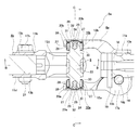
自在継手5aは、一般的にカルダン継手と呼ばれ、同一直線上に存在しない1対の軸同士の間で回転力の伝達を可能にするもので、1対の金属製(例えば炭素鋼鋳鋼材製)のヨーク8a、8bと、十字軸9と、4個のラジアルニードル軸受10a〜10dとを備えている。
The
1対のヨーク8a、8bのうち、一方のヨーク8aは、全体が略U字状に構成されており、基部11aと、該基部11aの軸方向一端縁(図1及び図2の左端縁)から延出した2本のアーム部12a、12bとを備えている。
Of the pair of
基部11aは、円周方向1個所を不連続部とした欠円筒状に構成されており、その内側に軸方向に貫通した取付孔13aが設けられている。そして、この取付孔13aに、電動アシスト装置7を構成する出力軸14の端部が挿入されている。また、基部11aのうち、円周方向に関して不連続部の両側に位置する部分に、互いに略平行に配置された1対の側板部15a、15bが設けられている。そして、このうちの一方の側板部15aに形成された通孔16aを挿通したボルト17aを、他方の側板部15bに形成された通孔16bの内周面に形成された雌ねじ、または通孔16bに内嵌固定されたナットに形成された雌ねじに螺合させている。これにより、基部11aを縮径して、出力軸14の端部外周面を取付孔13aの内周面により強く抑え付けている。また、出力軸14の端部とトーションバー18の端部とを跨いで設けられた連結軸19の一部を、1対の側板部15a、15b同士の間に配置して、ヨーク8aと出力軸14との相対回転を防止している。
The
アーム部12a、12bは、基部11aの軸方向一端部で径方向反対側となる2個所位置から軸方向に延出する状態で設けられており、それぞれが略平板状で、互いの内側面同士を対向させている。また、アーム部12a、12bの先端部には、アーム部12a、12bを板厚方向に貫通する、円形の貫通孔である軸受孔20a、20bが設けられている。これら1対の軸受孔20a、20bは、互いに同軸上に設けられている。
The
自在継手5aを構成する他方のヨーク8bも、基本的には、上述した一方のヨーク8aと同じ構成を有しており、基部11bと2本のアーム部12c、12dとを備えている。
The
基部11bは、円周方向1個所を不連続部とした欠円筒状に構成されており、その内側に軸方向に貫通した取付孔13bが設けられている。そして、この取付孔13bに、中間シャフト6を構成するインナシャフト21の端部が挿入されている。また、基部11bのうち、円周方向に関して不連続部の両側に位置する部分に、互いに略平行に配置された1対の側板部15c、15dが設けられている。そして、このうちの一方の側板部15cに形成された通孔を挿通したボルト17bを、他方の側板部15dに形成された通孔16cの内周面に形成された雌ねじ、または通孔16cに内嵌固定されたナットに形成された雌ねじに螺合させている。これにより、基部11bを縮径して、インナシャフト21の端部外周面を取付孔13bの内周面により強く抑え付けている。
The
アーム部12c、12dは、基部11bの軸方向他端部で径方向反対側となる2個所位置から軸方向に延出する状態で設けられており、それぞれが略平板状で、互いの内側面同士を対向させている。また、アーム部12c、12dの先端部には、アーム部12c、12dを板厚方向に貫通する、円形の貫通孔である軸受孔20c、20dが設けられている。これら1対の軸受孔20c、20dに関しても、互いに同軸上に設けられている。
The
十字軸9は、全体が十字状に構成されており、胴部22と、該胴部22の外周面から四方に突出した4本の軸部23a〜23dとを有している。4本の軸部23a〜23dは、胴部22の周囲に互いの位相を90度ずつずらして等間隔に配置されている。また、4本の軸部23a〜23dは、外径寸法が全長にわたり変化しない円柱状に構成されている。
The
軸部23a〜23dの軸方向先端面は平坦面であり、それぞれの中央部に開口する状態で、有底の挿入孔24が形成されている。そして、挿入孔24内に、弾性材製で略円柱状のピン25を、それぞれのピン25の先端部が軸部23a〜23dの軸方向先端面よりも軸方向に突出した状態で挿入(圧入)している。このようなピン25は、後述する軸受カップ26と軸部23a〜23dとの間で突っ張り、軸受カップ26の底板部29の内面と軸部23a〜23dの軸方向先端面との距離が縮まり過ぎることを防止する。
The axial tip end surfaces of the
上述のような構成を有する軸部23a〜23dの先端部を、軸受孔20a〜20dの内側に、ラジアルニードル軸受10a〜10dを使用して回転自在に支持している。
The tip portions of the
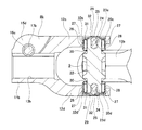
ラジアルニードル軸受10a〜10dはそれぞれ、有底円筒状の軸受カップ26と、複数本のニードル27とを備えている。このうちの軸受カップ26は、金属板を深絞り加工などの塑性加工により曲げ形成して成るもので、円筒状の嵌合筒部28と、円板状の底板部29と、内向鍔部30とを有している。
Each of the
嵌合筒部28は、軌道面として機能する内周面が、円筒面状に形成されている。底板部29は、嵌合筒部28の軸方向片側(軸受孔20a〜20d内への組み付け状態で、アーム部12a〜12dの外側面側)を塞ぐもので、外径側部分の屈曲部31と、中央部の円弧部32とを有している。屈曲部31は、ニードル27の端面と対向する内面が凸面となるように屈曲している。これに対し、円弧部32は、軸部23a〜23dの先端面と対向する内面が凹面(軸方向片側が凸面)となるように湾曲している。そして、自在継手5aの組立状態で、円弧部32の内面である凹曲面に対して、軸部23a〜23dに挿入されたピン25の先端部を弾性的に当接させるようにしている。また、円弧部32の内面の曲率半径は、ピン25の先端部の曲率半径よりも十分に大きくなっている。また、内向鍔部30は、嵌合筒部28の軸方向他側(軸受孔20a〜20d内への組み付け状態で、アーム部12a〜12dの内側面側)から径方向内方に折れ曲がる状態で設けられており、ニードル27と対向する面が凹面となる方向に湾曲している。
The fitting
ニードル27は、例えばステンレス鋼板などの金属板に深絞り加工などの塑性加工を施して造られており、嵌合筒部28の内周面と軸部23a〜23dの外周面との間に、転動自在に配置されている。特に本例では、ラジアルニードル軸受10a〜10dを構成する全てのニードル27が、軸部23a〜23dの先端側(軸受カップ26の底板部29側)に位置する軸方向片側部に底部33を有し、かつ、軸部23a〜23dの基端側(軸受カップ26の開口側)に位置する軸方向他側部に開口部34を有する、中空状に構成されている。このため、ニードル27は、底部33が設けられた軸方向片側部よりも開口部34が設けられた軸方向他側部で、ニードル27の直径方向に関する剛性が低くなっている。これにより、ニードル27は、少なくとも開口部34に近い軸方向他側部で、直径方向に弾性変形可能に構成されている。ニードル27の転動面35は、ニードル27の自由状態では、外径寸法が全長にわたり変化しない円筒面であるが、ニードル27の弾性変形状態では、断面形状がラジアル方向を短径とする楕円形状となる。また、短径と長径の差は、軸方向他側に向かうほど大きくなる。
The
図示の例では、ニードル27の肉厚(板厚)は、全体が円筒状に構成された転動面35部分と底部33とで同じに構成されているが、転動面35部分と底部33とで互いに異ならせても良い。また、転動面35部分の肉厚に関しても、全長にわたり同じにせずに、たとえば、底部33から離れるほど徐々に小さくする、あるいは、開口部34近傍のみを小さくするなど、転動面35部分の中で異ならせても良い。換言すれば、ニードル27の内径寸法を、軸方向にわたり変化させても良い。
In the illustrated example, the thickness (plate thickness) of the
ニードル27の底部33は、軸受カップ26の底板部29と対向する外面が凸面となるように湾曲した凸曲面となっている。
The bottom 33 of the
図5に梨子地模様で示すように、軸受カップ26の内側には、グリース37が充填されている。特に本例では、ニードル27を中空状に構成しているため、ニードル27の内部空間36にもグリース37が充填保持されている。
本例では、上述のようなラジアルニードル軸受10a〜10dを、軸受孔20a〜20dの内側に軸部23a〜23dをそれぞれ緩く挿入した状態で組み込む。すなわち、ヨーク8aに関して、同軸上に存在する1対の軸受孔20a、20bの内側に、軸部23a、23bをそれぞれ緩く挿入した状態で、アーム部12a、12bの外側面側からラジアルニードル軸受10a、10bを組み込む。同様に、ヨーク8bに関しても、同軸上に存在する1対の軸受孔20c、20dの内側に、軸部23c、23dをそれぞれ緩く挿入した状態で、アーム部12c、12dの外側面側からラジアルニードル軸受10c、10dを組み込む。
In this example, the
以上のような構成を有する本例では、軸部23a〜23dとニードル27との間に負の隙間を設定した十字軸式自在継手5aを、低コストで得られる。
すなわち、本例では、ラジアルニードル軸受10a〜10dを構成するニードル27を中空状に構成しているため、ニードル27の直径方向の剛性を調整することで、ニードル27の弾性変形量を容易に調整できる。このため、軸部23a〜23dの外径寸法とラジアルニードル軸受10a〜10dの内径寸法のばらつきを許容しながら、軸部23a〜23dとニードル27との間に負の隙間を設定することができる(締め代を設定できる)。したがって、軸部23a〜23dの外周面に対して要求される寸法精度を低くすることができる。このため、従来から行われていたマッチング作業を省略したり、軸部23a〜23dの外周面に対して行う切削加工や研削加工を省略したりすることも可能になる。つまり、軸部23a〜23dを含む十字軸9を、成形加工の精度のまま使用することが可能になる。この結果、本例では、軸部23a〜23dとニードル27との間に負の隙間を設定した自在継手5aを、低コストで得ることができる。
In this example having the above configuration, the cross-shaft universal joint 5a in which a negative gap is set between the
That is, in this example, since the
また、ニードル27の内部空間36にグリース37を充填することができるため、ニードル27自身に、グリース37の保持性能を持たせることができるとともに、開口部34を通じたグリース37の供給性能を持たせることができる。
Further, since the
また、ニードル27を、軸方向片側部に底部33を有し、かつ、軸方向他側部に開口部34を有する構造とすることで、ニードル27の直径方向に関する剛性を、軸方向片側部よりも軸方向他側部で低くしているため、軸部23a〜23dからラジアル方向の荷重が負荷された際の弾性変形量は、軸方向片側部よりも胴部22に近い軸方向他側部で大きくなる。このため、図7に示すように、ニードル27の転動面35と軸部23b(23a、23c、23d)の外周面との間に、断面楔状の隙間38を発生させることができる。したがって、ニードル27の弾性変形に基づき内部空間36から吐き出されたグリース37(図5参照)を、隙間38へと供給することができる。このため、グリース37が、軸受カップ26の外部へと漏れ出すことを有効に防止できる。また、楔効果により、ニードル27の転動面35と軸部23a〜23dの外周面との間にグリース37を効率良く供給することができ、軸部23a〜23dの回転抵抗を低減することが可能になる。
Further, the
さらに、ラジアルニードル軸受10a〜10dを、軸受孔20a〜20dの内側に組み込む際に、軸部23a〜23dを、ニードル27のうちで直径方向に関する剛性の低い軸方向他側部から挿入(圧入)することができる。このため、軸部23a〜23dの先端部をラジアルニードル軸受10a〜10dの内側に挿入する際に、軸部23a〜23dの先端部によってニードル27の軸方向他側部を大きく弾性変形させることができる。したがって、ニードル27と軸部23a〜23dとの接触状態を緩和することができ、転動面35及び軸部23a〜23dの外周面に、かじりや打痕などの表面損傷が生じることを防止できる。
Furthermore, when the
さらに、軸受カップ26を構成する底板部29の内面に対し、軸部23a〜23dの先端面を直接摺接させず、軸部23a〜23dの先端部に設けられたピン25の先端部を摺接させられるため、軸部23a〜23dが軸受カップ26に対して相対回転する際の摺接トルクを低く抑えられる。しかも、底板部29を構成する円弧部32の内面の曲率半径を、ピン25の先端部の曲率半径よりも十分に大きくしているため、軸部23a〜23dの中心軸とラジアルニードル軸受10a〜10dの中心軸とがずれた場合にも、軸部23a〜23dが軸受カップ26に対して相対回転する際の摺接トルクを低く抑えられる。
Furthermore, the tip end surfaces of the
[実施の形態の第2例]
実施の形態の第2例について、図8を用いて説明する。本例では、ニードル27aの開口側端部(軸方向他端部)に、径方向内方に折れ曲がるとともに外面が凸面となるように湾曲した、折れ曲がり部39を設けている。
Second Example of Embodiment
A second example of the embodiment will be described with reference to FIG. In this example, a
以上のような構成を有する本例では、軸部23b(23a、23c、23d)をラジアルニードル軸受10b(10a、10c、10d)の内側に挿入(圧入)する際に、軸部23b(23a、23c、23d)の先端部外周縁部がニードル27aの開口側端部に引っ掛かることを有効に防止できる。このため、軸部23b(23a、23c、23d)の挿入作業をより効率良く行うことができる。さらに、ニードル27aの開口側端部に折れ曲がり部39を設けることで、ニードル27aの開口部がすぼまっているため、グリース37(図5参照)の保持性能を向上することができる。
その他の構成及び作用効果については、実施の形態の第1例と同じである。
In this example having the above configuration, when inserting (press-fitting) the
Other configurations and operational effects are the same as the first example of the embodiment.
[実施の形態の第3例]
実施の形態の第3例について、図9を用いて説明する。本例では、ラジアルニードル軸受10b(10a、10c、10d)の内側に挿入される軸部23b(23a、23c、23d)を、段付軸としている。具体的には、軸部23b(23a、23c、23d)を、周囲にニードル27が配置される先端側の小径軸部40と、基端側の大径軸部41と、これら小径軸部40と大径軸部41とをつなぐ段差部42とにより構成している。段差部42は、ニードル27の開口側端部(軸方向他端部)よりも、軸部23b(23a、23c、23d)の基端側に位置している。
Third Example of Embodiment
A third example of the embodiment will be described with reference to FIG. In this example, the
以上のような構成を有する本例では、軸部23b(23a、23c、23d)の外周面に段差部42を設けているため、図示のように、小径軸部40からニードル27にラジアル方向の荷重が負荷された際に生じる断面楔状の隙間38に、グリース37(図5参照)を効率良く供給することができる。また、隙間38内に供給されたグリース37を、段差部42によって堰き止めることができるため、隙間38内にグリース37を保持し易くなる。さらに、ニードル27の開口側端部と段差部42とを当接させることで、ニードル27の軸方向の移動(暴れ)を抑制できるとともに、ニードル27のスキューを抑制することもできる。
その他の構成及び作用効果については、実施の形態の第1例と同じである。
In the present example having the above-described configuration, since the
Other configurations and operational effects are the same as the first example of the embodiment.
[実施の形態の第4例]
実施の形態の第4例について、図10を用いて説明する。本例では、ニードル27bの外径寸法が、軸部23b(23a、23c、23d)の先端側に位置する軸方向片側部から軸部23b(23a、23c、23d)の基端側に位置する軸方向他側部に向かうほど小さくなったものを使用している。つまり、ニードル27bの転動面35aは、ニードル27bの自由状態で、外径寸法が軸方向他側(胴部22側)に向かうほど小さくなったテーパ面になっている。
Fourth Example of Embodiment
A fourth example of the embodiment will be described with reference to FIG. In this example, the outer diameter of the
さらに本例では、軸部23b(23a、23c、23d)を、先端側から基端側に向かうほど外径寸法が小さくなったテーパ軸としている。
Furthermore, in the present embodiment, the
以上のような構成を有する本例では、軸部23b(23a、23c、23d)からニードル27bにラジアル方向の荷重が負荷される以前の状態で、軸部23b(23a、23c、23d)の外周面とニードル27bの転動面35aとの間に、断面楔状の隙間38aを形成することができる。したがって、本例では、ラジアル方向の荷重が負荷される前と負荷された後との何れの場合にも、断面楔状の隙間38aに、グリース37(図5参照)を保持することができる。
なお、本例では、ニードル27bの転動面35aと軸部23b(23a、23c、23d)の外周面の両方をテーパ面とした場合について説明したが、ニードルの転動面と軸部の外周面のいずれか一方をテーパ面とし、他方を円筒面とすることもできる。
その他の構成及び作用効果については、実施の形態の第1例と同じである。
In this example having the above configuration, the outer periphery of the
In this example, although the case where both the rolling
Other configurations and operational effects are the same as the first example of the embodiment.
本発明を実施する場合に、例えばニードルの弾性変形量が過大になる場合には、ラジアルニードル軸受を構成する全てのニードルを中空状とせずに、中実状のニードルを混在させる(たとえば円周方向に関して交互に配置する)ことで、中空状のニードルの弾性変形量を所定量以下に抑えることもできる。
また、本発明を実施する場合には、前述した実施の形態の各例の構造を適宜組み合わせて実施することもできる。
In the practice of the present invention, for example, when the amount of elastic deformation of the needles becomes excessive, solid needles are mixed without making all the needles constituting the radial needle bearing hollow (for example, in the circumferential direction) Alternatively, the amount of elastic deformation of the hollow needle can be suppressed to a predetermined amount or less by alternately arranging them.
Moreover, when implementing this invention, it can also be implemented combining the structure of each example of embodiment mentioned above suitably.
1 自動車用操舵装置
2 ステアリングホイール
3 ステアリングシャフト
4 ステアリングコラム
5a、5b 自在継手
6 中間シャフト
7 電動アシスト装置
8a、8b ヨーク
9 十字軸
10a〜10d ラジアルニードル軸受
11a、11b 基部
12a〜12d アーム部
13a、13b 取付孔
14 出力軸
15a〜15d 側板部
16a、16b、16c 通孔
17a、17b ボルト
18 トーションバー
19 連結軸
20a〜20d 軸受孔
21 インナシャフト
22 胴部
23a〜23d 軸部
24 挿入孔
25 ピン
26 軸受カップ
27、27a、27b ニードル
28 嵌合筒部
29 底板部
30 内向鍔部
31 屈曲部
32 円弧部
33 底部
34 開口部
35、35a 転動面
36 内部空間
37 グリース
38、38a 隙間
39 折れ曲がり部
40 小径軸部
41 大径軸部
42 段差部
1 Steering device for
Claims (9)
前記軸受孔の内側に内嵌固定される有底円筒状の軸受カップと、前記軸受カップの内周面と前記軸部の外周面との間に転動自在に配置される複数本のニードルとを備えており、
前記複数本のニードルのうち少なくとも1本のニードルが、前記軸部の先端側に底部を有しかつ前記軸部の基端側に開口部を有する中空状に構成されている、
ラジアルニードル軸受。 A radial needle bearing for rotatably supporting a shaft portion constituting a cross shaft inside a bearing hole formed in an arm portion constituting a yoke, comprising:
A bottomed cylindrical bearing cup internally fitted and fixed to the inside of the bearing hole, and a plurality of needles rotatably disposed between an inner circumferential surface of the bearing cup and an outer circumferential surface of the shaft portion; Equipped with
At least one needle among the plurality of needles is configured in a hollow shape having a bottom on the tip end side of the shaft and an opening on the base end side of the shaft.
Radial needle bearing.
4本の軸部を有する十字軸と、
前記各軸受孔の内側に前記各軸部をそれぞれ回転自在に支持する4個のラジアルニードル軸受と、
を備える十字軸式自在継手であって、
前記4個のラジアルニードル軸受のうち少なくとも1個のラジアルニードル軸受が、請求項1〜6のうちのいずれか1項に記載したラジアルニードル軸受である、十字軸式自在継手。 A pair of yokes having two arm portions provided with bearing holes respectively;
A cross shaft with four shaft parts,
Four radial needle bearings rotatably supporting the shafts at the inside of the bearing holes,
A universal joint having a shaft
A cross shaft universal joint in which at least one of the four radial needle bearings is the radial needle bearing according to any one of claims 1 to 6.
Priority Applications (1)
| Application Number | Priority Date | Filing Date | Title |
|---|---|---|---|
| JP2017232615A JP2019100466A (en) | 2017-12-04 | 2017-12-04 | Radial needle bearing and cross shaft type universal joint |
Applications Claiming Priority (1)
| Application Number | Priority Date | Filing Date | Title |
|---|---|---|---|
| JP2017232615A JP2019100466A (en) | 2017-12-04 | 2017-12-04 | Radial needle bearing and cross shaft type universal joint |
Publications (1)
| Publication Number | Publication Date |
|---|---|
| JP2019100466A true JP2019100466A (en) | 2019-06-24 |
Family
ID=66976541
Family Applications (1)
| Application Number | Title | Priority Date | Filing Date |
|---|---|---|---|
| JP2017232615A Pending JP2019100466A (en) | 2017-12-04 | 2017-12-04 | Radial needle bearing and cross shaft type universal joint |
Country Status (1)
| Country | Link |
|---|---|
| JP (1) | JP2019100466A (en) |
Cited By (1)
| Publication number | Priority date | Publication date | Assignee | Title |
|---|---|---|---|---|
| KR102094869B1 (en) * | 2018-10-26 | 2020-03-30 | 현대트랜시스 주식회사 | Air cushion device of manual transmission |
-
2017
- 2017-12-04 JP JP2017232615A patent/JP2019100466A/en active Pending
Cited By (1)
| Publication number | Priority date | Publication date | Assignee | Title |
|---|---|---|---|---|
| KR102094869B1 (en) * | 2018-10-26 | 2020-03-30 | 현대트랜시스 주식회사 | Air cushion device of manual transmission |
Similar Documents
| Publication | Publication Date | Title |
|---|---|---|
| WO2011102212A1 (en) | Joint cross type universal joint yoke and method of manufacturing same | |
| US8813594B2 (en) | Rack and pinion steering gear unit | |
| JP5417840B2 (en) | Steering device | |
| EP3009329B1 (en) | Rack-and-pinion steering gear unit | |
| EP3643582B1 (en) | Shaft for steering device, method for manufacturing shaft for steering device, and electric power steering device | |
| JP5326765B2 (en) | Electric power steering device | |
| JP4275765B2 (en) | Electric cylinder device and manufacturing method thereof | |
| US8986126B2 (en) | Cross universal joint and manufacturing method thereof | |
| JP2019100466A (en) | Radial needle bearing and cross shaft type universal joint | |
| JP5618146B2 (en) | Electric power steering device | |
| JP6673308B2 (en) | Torque transmission shaft for steering | |
| JP2019537694A (en) | Fixed bearings and steering gears | |
| JP2006151043A (en) | Electric power steering device | |
| WO2020153408A1 (en) | Torque transmission shaft | |
| JP6287181B2 (en) | Fixing method of inner ring for rolling bearing | |
| JP2001254755A (en) | Universal joint yoke | |
| JP2013007418A (en) | Bearing support structure and electric power steering device | |
| JP2019078273A (en) | Torque transmission shaft | |
| JP2019027443A (en) | Joint spider and joint spider type universal joint | |
| JP6524937B2 (en) | Cross joint | |
| JP2011220417A (en) | Joint cross type universal joint yoke | |
| JP2018084250A (en) | Cross axis type universal joint | |
| JP2013047543A (en) | Joint york and joint | |
| JP2026041147A (en) | Self-aligning ball bearing | |
| JP2018052323A (en) | Steering shaft |