JP2018506154A - Pogo pin connector - Google Patents
Pogo pin connector Download PDFInfo
- Publication number
- JP2018506154A JP2018506154A JP2017541361A JP2017541361A JP2018506154A JP 2018506154 A JP2018506154 A JP 2018506154A JP 2017541361 A JP2017541361 A JP 2017541361A JP 2017541361 A JP2017541361 A JP 2017541361A JP 2018506154 A JP2018506154 A JP 2018506154A
- Authority
- JP
- Japan
- Prior art keywords
- connector
- sensor assembly
- sensor
- proximal end
- electrical contacts
- Prior art date
- Legal status (The legal status is an assumption and is not a legal conclusion. Google has not performed a legal analysis and makes no representation as to the accuracy of the status listed.)
- Granted
Links
Images


Classifications
-
- H—ELECTRICITY
- H01—ELECTRIC ELEMENTS
- H01R—ELECTRICALLY-CONDUCTIVE CONNECTIONS; STRUCTURAL ASSOCIATIONS OF A PLURALITY OF MUTUALLY-INSULATED ELECTRICAL CONNECTING ELEMENTS; COUPLING DEVICES; CURRENT COLLECTORS
- H01R24/00—Two-part coupling devices, or either of their cooperating parts, characterised by their overall structure
- H01R24/60—Contacts spaced along planar side wall transverse to longitudinal axis of engagement
- H01R24/62—Sliding engagements with one side only, e.g. modular jack coupling devices
-
- A—HUMAN NECESSITIES
- A61—MEDICAL OR VETERINARY SCIENCE; HYGIENE
- A61B—DIAGNOSIS; SURGERY; IDENTIFICATION
- A61B5/00—Measuring for diagnostic purposes; Identification of persons
- A61B5/02—Detecting, measuring or recording for evaluating the cardiovascular system, e.g. pulse, heart rate, blood pressure or blood flow
- A61B5/021—Measuring pressure in heart or blood vessels
-
- A—HUMAN NECESSITIES
- A61—MEDICAL OR VETERINARY SCIENCE; HYGIENE
- A61B—DIAGNOSIS; SURGERY; IDENTIFICATION
- A61B5/00—Measuring for diagnostic purposes; Identification of persons
- A61B5/145—Measuring characteristics of blood in vivo, e.g. gas concentration or pH-value ; Measuring characteristics of body fluids or tissues, e.g. interstitial fluid or cerebral tissue
- A61B5/1455—Measuring characteristics of blood in vivo, e.g. gas concentration or pH-value ; Measuring characteristics of body fluids or tissues, e.g. interstitial fluid or cerebral tissue using optical sensors, e.g. spectral photometrical oximeters
-
- H—ELECTRICITY
- H01—ELECTRIC ELEMENTS
- H01R—ELECTRICALLY-CONDUCTIVE CONNECTIONS; STRUCTURAL ASSOCIATIONS OF A PLURALITY OF MUTUALLY-INSULATED ELECTRICAL CONNECTING ELEMENTS; COUPLING DEVICES; CURRENT COLLECTORS
- H01R13/00—Details of coupling devices of the kinds covered by groups H01R12/70 or H01R24/00 - H01R33/00
- H01R13/02—Contact members
- H01R13/193—Means for increasing contact pressure at the end of engagement of coupling part, e.g. zero insertion force or no friction
-
- H—ELECTRICITY
- H01—ELECTRIC ELEMENTS
- H01R—ELECTRICALLY-CONDUCTIVE CONNECTIONS; STRUCTURAL ASSOCIATIONS OF A PLURALITY OF MUTUALLY-INSULATED ELECTRICAL CONNECTING ELEMENTS; COUPLING DEVICES; CURRENT COLLECTORS
- H01R13/00—Details of coupling devices of the kinds covered by groups H01R12/70 or H01R24/00 - H01R33/00
- H01R13/02—Contact members
- H01R13/22—Contacts for co-operating by abutting
- H01R13/24—Contacts for co-operating by abutting resilient; resiliently-mounted
- H01R13/2407—Contacts for co-operating by abutting resilient; resiliently-mounted characterized by the resilient means
- H01R13/2421—Contacts for co-operating by abutting resilient; resiliently-mounted characterized by the resilient means using coil springs
-
- H—ELECTRICITY
- H01—ELECTRIC ELEMENTS
- H01R—ELECTRICALLY-CONDUCTIVE CONNECTIONS; STRUCTURAL ASSOCIATIONS OF A PLURALITY OF MUTUALLY-INSULATED ELECTRICAL CONNECTING ELEMENTS; COUPLING DEVICES; CURRENT COLLECTORS
- H01R13/00—Details of coupling devices of the kinds covered by groups H01R12/70 or H01R24/00 - H01R33/00
- H01R13/62—Means for facilitating engagement or disengagement of coupling parts or for holding them in engagement
- H01R13/627—Snap or like fastening
- H01R13/6271—Latching means integral with the housing
- H01R13/6272—Latching means integral with the housing comprising a single latching arm
-
- H—ELECTRICITY
- H01—ELECTRIC ELEMENTS
- H01R—ELECTRICALLY-CONDUCTIVE CONNECTIONS; STRUCTURAL ASSOCIATIONS OF A PLURALITY OF MUTUALLY-INSULATED ELECTRICAL CONNECTING ELEMENTS; COUPLING DEVICES; CURRENT COLLECTORS
- H01R13/00—Details of coupling devices of the kinds covered by groups H01R12/70 or H01R24/00 - H01R33/00
- H01R13/64—Means for preventing incorrect coupling
- H01R13/641—Means for preventing incorrect coupling by indicating incorrect coupling; by indicating correct or full engagement
-
- H—ELECTRICITY
- H01—ELECTRIC ELEMENTS
- H01R—ELECTRICALLY-CONDUCTIVE CONNECTIONS; STRUCTURAL ASSOCIATIONS OF A PLURALITY OF MUTUALLY-INSULATED ELECTRICAL CONNECTING ELEMENTS; COUPLING DEVICES; CURRENT COLLECTORS
- H01R13/00—Details of coupling devices of the kinds covered by groups H01R12/70 or H01R24/00 - H01R33/00
- H01R13/648—Protective earth or shield arrangements on coupling devices, e.g. anti-static shielding
- H01R13/6485—Electrostatic discharge protection
-
- H—ELECTRICITY
- H01—ELECTRIC ELEMENTS
- H01R—ELECTRICALLY-CONDUCTIVE CONNECTIONS; STRUCTURAL ASSOCIATIONS OF A PLURALITY OF MUTUALLY-INSULATED ELECTRICAL CONNECTING ELEMENTS; COUPLING DEVICES; CURRENT COLLECTORS
- H01R13/00—Details of coupling devices of the kinds covered by groups H01R12/70 or H01R24/00 - H01R33/00
- H01R13/648—Protective earth or shield arrangements on coupling devices, e.g. anti-static shielding
- H01R13/652—Protective earth or shield arrangements on coupling devices, e.g. anti-static shielding with earth pin, blade or socket
-
- H—ELECTRICITY
- H01—ELECTRIC ELEMENTS
- H01R—ELECTRICALLY-CONDUCTIVE CONNECTIONS; STRUCTURAL ASSOCIATIONS OF A PLURALITY OF MUTUALLY-INSULATED ELECTRICAL CONNECTING ELEMENTS; COUPLING DEVICES; CURRENT COLLECTORS
- H01R13/00—Details of coupling devices of the kinds covered by groups H01R12/70 or H01R24/00 - H01R33/00
- H01R13/66—Structural association with built-in electrical component
- H01R13/665—Structural association with built-in electrical component with built-in electronic circuit
- H01R13/6683—Structural association with built-in electrical component with built-in electronic circuit with built-in sensor
-
- A—HUMAN NECESSITIES
- A61—MEDICAL OR VETERINARY SCIENCE; HYGIENE
- A61B—DIAGNOSIS; SURGERY; IDENTIFICATION
- A61B2562/00—Details of sensors; Constructional details of sensor housings or probes; Accessories for sensors
- A61B2562/22—Arrangements of medical sensors with cables or leads; Connectors or couplings specifically adapted for medical sensors
- A61B2562/225—Connectors or couplings
- A61B2562/227—Sensors with electrical connectors
-
- H—ELECTRICITY
- H01—ELECTRIC ELEMENTS
- H01R—ELECTRICALLY-CONDUCTIVE CONNECTIONS; STRUCTURAL ASSOCIATIONS OF A PLURALITY OF MUTUALLY-INSULATED ELECTRICAL CONNECTING ELEMENTS; COUPLING DEVICES; CURRENT COLLECTORS
- H01R12/00—Structural associations of a plurality of mutually-insulated electrical connecting elements, specially adapted for printed circuits, e.g. printed circuit boards [PCB], flat or ribbon cables, or like generally planar structures, e.g. terminal strips, terminal blocks; Coupling devices specially adapted for printed circuits, flat or ribbon cables, or like generally planar structures; Terminals specially adapted for contact with, or insertion into, printed circuits, flat or ribbon cables, or like generally planar structures
- H01R12/70—Coupling devices
- H01R12/71—Coupling devices for rigid printing circuits or like structures
- H01R12/712—Coupling devices for rigid printing circuits or like structures co-operating with the surface of the printed circuit or with a coupling device exclusively provided on the surface of the printed circuit
- H01R12/714—Coupling devices for rigid printing circuits or like structures co-operating with the surface of the printed circuit or with a coupling device exclusively provided on the surface of the printed circuit with contacts abutting directly the printed circuit; Button contacts therefore provided on the printed circuit
-
- H—ELECTRICITY
- H01—ELECTRIC ELEMENTS
- H01R—ELECTRICALLY-CONDUCTIVE CONNECTIONS; STRUCTURAL ASSOCIATIONS OF A PLURALITY OF MUTUALLY-INSULATED ELECTRICAL CONNECTING ELEMENTS; COUPLING DEVICES; CURRENT COLLECTORS
- H01R12/00—Structural associations of a plurality of mutually-insulated electrical connecting elements, specially adapted for printed circuits, e.g. printed circuit boards [PCB], flat or ribbon cables, or like generally planar structures, e.g. terminal strips, terminal blocks; Coupling devices specially adapted for printed circuits, flat or ribbon cables, or like generally planar structures; Terminals specially adapted for contact with, or insertion into, printed circuits, flat or ribbon cables, or like generally planar structures
- H01R12/70—Coupling devices
- H01R12/71—Coupling devices for rigid printing circuits or like structures
- H01R12/72—Coupling devices for rigid printing circuits or like structures coupling with the edge of the rigid printed circuits or like structures
- H01R12/721—Coupling devices for rigid printing circuits or like structures coupling with the edge of the rigid printed circuits or like structures cooperating directly with the edge of the rigid printed circuits
-
- H—ELECTRICITY
- H01—ELECTRIC ELEMENTS
- H01R—ELECTRICALLY-CONDUCTIVE CONNECTIONS; STRUCTURAL ASSOCIATIONS OF A PLURALITY OF MUTUALLY-INSULATED ELECTRICAL CONNECTING ELEMENTS; COUPLING DEVICES; CURRENT COLLECTORS
- H01R13/00—Details of coupling devices of the kinds covered by groups H01R12/70 or H01R24/00 - H01R33/00
- H01R13/62—Means for facilitating engagement or disengagement of coupling parts or for holding them in engagement
- H01R13/627—Snap or like fastening
- H01R13/6278—Snap or like fastening comprising a pin snapping into a recess
-
- H—ELECTRICITY
- H01—ELECTRIC ELEMENTS
- H01R—ELECTRICALLY-CONDUCTIVE CONNECTIONS; STRUCTURAL ASSOCIATIONS OF A PLURALITY OF MUTUALLY-INSULATED ELECTRICAL CONNECTING ELEMENTS; COUPLING DEVICES; CURRENT COLLECTORS
- H01R13/00—Details of coupling devices of the kinds covered by groups H01R12/70 or H01R24/00 - H01R33/00
- H01R13/62—Means for facilitating engagement or disengagement of coupling parts or for holding them in engagement
- H01R13/629—Additional means for facilitating engagement or disengagement of coupling parts, e.g. aligning or guiding means, levers, gas pressure electrical locking indicators, manufacturing tolerances
-
- H—ELECTRICITY
- H01—ELECTRIC ELEMENTS
- H01R—ELECTRICALLY-CONDUCTIVE CONNECTIONS; STRUCTURAL ASSOCIATIONS OF A PLURALITY OF MUTUALLY-INSULATED ELECTRICAL CONNECTING ELEMENTS; COUPLING DEVICES; CURRENT COLLECTORS
- H01R2201/00—Connectors or connections adapted for particular applications
- H01R2201/12—Connectors or connections adapted for particular applications for medicine and surgery
Landscapes
- Health & Medical Sciences (AREA)
- Life Sciences & Earth Sciences (AREA)
- Physics & Mathematics (AREA)
- Engineering & Computer Science (AREA)
- Molecular Biology (AREA)
- General Health & Medical Sciences (AREA)
- Cardiology (AREA)
- Biophysics (AREA)
- Pathology (AREA)
- Biomedical Technology (AREA)
- Heart & Thoracic Surgery (AREA)
- Medical Informatics (AREA)
- Veterinary Medicine (AREA)
- Surgery (AREA)
- Animal Behavior & Ethology (AREA)
- Public Health (AREA)
- Optics & Photonics (AREA)
- Spectroscopy & Molecular Physics (AREA)
- Vascular Medicine (AREA)
- Physiology (AREA)
- Microelectronics & Electronic Packaging (AREA)
- Details Of Connecting Devices For Male And Female Coupling (AREA)
- Measurement Of The Respiration, Hearing Ability, Form, And Blood Characteristics Of Living Organisms (AREA)
- Measuring And Recording Apparatus For Diagnosis (AREA)
- Measuring Fluid Pressure (AREA)
- Push-Button Switches (AREA)
Abstract
様々なコネクタ及びセンサアセンブリが記載される。いくつかの実施形態では、コネクタ及びセンサアセンブリはコネクタとセンサアセンブリとを備える。コネクタは、互いに対向する第1の面及び第2の面を有する開口部を有することができる。コネクタは、第1の面から延在する複数の伸縮自在な電気コネクタと、第2の面に配置されたロック構造と、を有することができる。センサアセンブリは、本体部分と近位端とを備える。近位端は頂面及び底面を有する。頂面は複数の伸縮自在な電気コネクタと相互作用するように構成された複数の電気接点を含む。底面はコネクタのロック構造と相互作用するように構成された鍵構造を含む。Various connectors and sensor assemblies are described. In some embodiments, the connector and sensor assembly comprises a connector and a sensor assembly. The connector can have an opening having a first surface and a second surface facing each other. The connector can have a plurality of telescopic electrical connectors extending from the first surface and a locking structure disposed on the second surface. The sensor assembly includes a body portion and a proximal end. The proximal end has a top surface and a bottom surface. The top surface includes a plurality of electrical contacts configured to interact with a plurality of telescopic electrical connectors. The bottom surface includes a key structure configured to interact with the locking structure of the connector.
Description
本発明は電気コネクタに関する。より具体的には、本開示は、医療センサの、このセンサからの信号に応じた機器への接続に関する。 The present invention relates to an electrical connector. More specifically, the present disclosure relates to connecting a medical sensor to equipment in response to a signal from the sensor.
エネルギーは、媒体の特性を測定するためにこの媒体を透過又は反射される場合が多い。例えば医療分野では、検査のために患者の体内から物質を抽出する代わりに、光又は音のエネルギーを患者の身体に入射させ、伝達された(又は反射された)エネルギーを測定して、エネルギーが通過した物質についての情報を決定するように測定することができる。このタイプの測定は、患者にとってはより快適であり、より迅速に行うことができる。 The energy is often transmitted or reflected through the medium to measure the characteristics of the medium. For example, in the medical field, instead of extracting material from the patient's body for examination, light or sound energy is incident on the patient's body and the transmitted (or reflected) energy is measured and the energy is Measurements can be made to determine information about the material passed through. This type of measurement is more comfortable for the patient and can be performed more quickly.
身体機能の非侵襲的な生理学的モニタリングが必要とされる場合が多い。例えば、手術中に、血圧及び身体の利用可能な酸素供給量又は血液酸素飽和度が監視されることが多い。これらのような測定は、身体、例えば手の指のような指、若しくは耳たぶ、若しくは額の一部を透過した(又は反射した)光に対する入射光の比を測定することによって評価が行われる、非侵襲的な技術によって行われることが多い。 Non-invasive physiological monitoring of body function is often required. For example, during surgery, blood pressure and the body's available oxygen supply or blood oxygen saturation are often monitored. Measurements such as these are evaluated by measuring the ratio of incident light to light transmitted (or reflected) through the body, for example a finger such as a finger of a hand, or an earlobe, or part of the forehead, Often done by non-invasive techniques.
耐久性を有する使い捨て式センサがそのような生理学的測定に使用される場合が多い。これらセンサは、機器からの取り外しを可能にするコネクタ又は機器からのケーブルを有する。 Durable disposable sensors are often used for such physiological measurements. These sensors have a connector or cable from the device that allows for removal from the device.
本開示は、使い捨て式であるとともに耐久性を有するセンサを、センサからの信号に応答する機器又はこの機器からのケーブルに取り付けるように構成されたコネクタに関する。適切な作動を確実とするために、コネクタは、このコネクタへのプローブへの誤った取り付けを防止するように設計されている。さらに、このコネクタは簡単な接続と解放を可能にし、さらに偶発的な断線を防ぐ。 The present disclosure relates to a connector configured to attach a sensor that is disposable and durable to a device that responds to a signal from the sensor or a cable from the device. In order to ensure proper operation, the connector is designed to prevent erroneous attachment to the probe to this connector. In addition, this connector allows for easy connection and release, and prevents accidental disconnection.
本開示のいくつかの観点では、薄型の構造を有するセンサと、様々な身体機能を測定する別々のセンサに適合するように構成することができるコネクタと、が開示される。一実施形態では、コネクタは、センサ上の複数のジグザグ状の電気接点を有するセンサと相互作用する複数のジグザグ状の伸縮自在な接点に適合することができる。 In some aspects of the present disclosure, a sensor having a thin structure and a connector that can be configured to fit different sensors that measure various body functions are disclosed. In one embodiment, the connector can accommodate a plurality of zigzag telescopic contacts that interact with a sensor having a plurality of zigzag electrical contacts on the sensor.
いくつかの実施形態では、本開示は、コネクタとセンサアセンブリを含む。センサアセンブリは、互いに対向する第1の面と第2の面とを有する開口部を有するコネクタを含む。この例では、複数の伸縮自在な電気コネクタは、第1の面から延びることができ、ロック構造を第2の面上に配置することができる。この実施形態では、センサアセンブリは、本体部分と近位端とを含む。近位端は頂面および底面を含み、頂面は複数の電気接点を含み、底面は、コネクタのロック構造にぴったり合うように構成された鍵構造および戻り止め構造を備える。この例では、センサアセンブリの近位端は、コネクタの開口部の中に取り外し可能に挿入されるように構成されている。 In some embodiments, the present disclosure includes a connector and a sensor assembly. The sensor assembly includes a connector having an opening having a first surface and a second surface facing each other. In this example, the plurality of telescopic electrical connectors can extend from the first surface and the locking structure can be disposed on the second surface. In this embodiment, the sensor assembly includes a body portion and a proximal end. The proximal end includes a top surface and a bottom surface, the top surface includes a plurality of electrical contacts, and the bottom surface includes a key structure and a detent structure configured to closely fit the locking structure of the connector. In this example, the proximal end of the sensor assembly is configured to be removably inserted into the opening of the connector.
本開示は、センサ又はプローブをモニタ又はプロセッサに取り付け、それによってセンサからの信号をプロセッサ又はモニタに伝送するためのコネクタを開示する。このコネクタは、確実な接続を維持しつつ、センサのコネクタへの容易な接続及び取り外しを提供する。適切な作動を確実にするために、コネクタは、このコネクタへのプローブの正しくない取り付けを防止するように設計されている。さらに、いくつかの実施形態では、コネクタとセンサとは、コネクタ構造とセンサ構造との両方を、別々の体の機能を測定する別々のセンサを収容するように、調整することができるように構成されている。 The present disclosure discloses a connector for attaching a sensor or probe to a monitor or processor, thereby transmitting signals from the sensor to the processor or monitor. This connector provides easy connection and disconnection of the sensor to the connector while maintaining a secure connection. In order to ensure proper operation, the connector is designed to prevent incorrect attachment of the probe to the connector. Further, in some embodiments, the connector and sensor are configured such that both the connector structure and the sensor structure can be adjusted to accommodate separate sensors that measure separate body functions. Has been.
本明細書において使用されているように、用語「近位」及び「遠位」は、説明されるコネクタとセンサアセンブリとの間の接点に対するものであることを理解すべきである。したがって、用語「遠位」は、コネクタ及び/又はセンサの間の接点(接続点)から最も離れた、コネクタ及び/又はセンサアセンブリの部分を意味する。用語「近位」は、コネクタ及び/又はセンサアセンブリの間の接点(接続点)に最も近い、コネクタ及び/又はセンサアセンブリの部分を意味する。 As used herein, it should be understood that the terms “proximal” and “distal” are relative to the contacts between the described connector and the sensor assembly. Thus, the term “distal” means the portion of the connector and / or sensor assembly that is furthest away from the contact (connecting point) between the connector and / or sensor. The term “proximal” means the part of the connector and / or sensor assembly that is closest to the contact (connection point) between the connector and / or sensor assembly.
図1A〜1Dは、アセンブリ100の一実施形態の側面斜視図を示し、このアセンブリ100はコネクタ200及びセンサアセンブリ800aを含む。コネクタ200は、コネクタ200の近位端における開口420aを通じてセンサアセンブリ800aと接続するように構成されている。これは、センサタブ810aが、センサアセンブリレシーバ400aによって固定されることを可能にする。コネクタ200は、特定のセンサアセンブリ又は複数のセンサアセンブリと相互作用するように構成された電気コネクタを有するように構成することができる。一実施形態では、適切なセンサアセンブリが対応するコネクタ200に接続されることを確実にするために、コネクタ200のセンサアセンブリレシーバ400aは、対応する構造を有するセンサアセンブリのみを受容するように構成された内部構造を有することができる。これは、センサを互換性の無いコネクタと取り付けることにおける間違いを防止する。いくつかの例では、コネクタ200は対応する鍵を有するセンサアセンブリのみを受容するレセプタを有する。図1A〜1Dに見ることができるように、センサアセンブリレシーバ400aはセンサアセンブリレシーバ400aの底内面に沿って配置されたレセプタ445aを有し、センサタブ810aはセンサタブ810aの下面に配置された鍵860aを有する。上述したように、レセプタ445aは、対応する鍵860aを有するセンサアセンブリだけが、コネクタ200中へ嵌合するのを可能にする。レセプタ445a及び鍵860aの配置は、使用者が、センサタブ810aをコネクタ200にセンサ面812aが上を向いて位置するような正しい構成で接続することを確実にする。
1A-1D show side perspective views of one embodiment of
いくつかの実施形態では、コネクタ200及びセンサアセンブリ800aは、センサアセンブリ800aのコネクタ200との接続を容易とするための表面を有して構成される。例えば、コネクタ200の近位端は前端220及び、センサアセンブリレシーバ400aの開口420a中に曲がる(angles into)、テーパの付いた面430aを有する。同様に、図1Dに示すように、センサアセンブリ800aは、コネクタタブ840aを有するセンサタブ810aより遠位であるテーパの付けられた面820aを有する近位端を有する。テーパを付けられた面820aの角度は、コネクタ200のテーパの付けられた面430aの角度と一致し、使用者にセンサアセンブリ800aをコネクタ200のセンサアセンブリレシーバ400a中へ容易に滑動させることを可能にする面を提供する。コネクタ200の前端220は、センサアセンブリ800aのテーパの付けられた面820aを閉止するように延び、それによって前端220は、テーパの付けられた面820aの遠位端の外縁にわたって同一平面に存在する。コネクタ220と、センサアセンブリ800aと、の間の平坦な接続は、使用者にコネクタ200及びセンサアセンブリ800aが適切に接続されていることを示す連続構造又はシールを提供する。前述の構造は、使用者がセンサをコネクタに感触だけによって正しく取り付けることを可能にする。これは、明かりが不十分である状況において、患者及び医師がコネクタ200をセンサアセンブリ800aに取り付けるのを助け、それによって使用者がコネクタ200を、コネクタそれ自体を見る必要なくセンサアセンブリ800aと接続するのを可能にする。
In some embodiments,
図2A及び2Bは、コネクタ200の一実施形態の別々の図を提供する。なお、図2A及び2Bは、コネクタ200の斜視図及び正面図を提供する。図3は、コネクタ200のさらなる内部構造が視認できるように、外側ジャケットが取り外されたコネクタ200を示す。図4A及び4Bは、プリント回路板500及び内側シールド600が視認できるように外側シールドが取り外されたコネクタ200の2つの図が示されている。また、図4A及び4Bは、プリント回路板500の孔の中に配置された複数のポゴピンと、内側シールド600と、を図示している。図5Aは、プリント回路板500の斜視図を示している。図6Aは、プリント回路板が取り外された状態で、図4A及び4Bに示された実施形態を示す。図7Aは、プリント回路板500及び内側シールド600の底面斜視図を示す。図8A及び8Bは、内側シールド600が取り外された状態の図4A及び図4Bに図示された実施形態の底面斜視図及び頂面斜視図を示す。
2A and 2B provide separate views of one embodiment of the
図2A及び2Bは、コネクタ200の斜視図及び正面図を示す。コネクタ200は、後述に、より詳細に説明される多くの特徴を含む。コネクタ200は外側ジャケット210、近位端上の前端220、及び遠位端におけるケーブルアタッチメント230を有する。上述に述べたように、前端220はテーパを付けられた面820aの遠位端の外縁周りに配置されるように構成されている。コネクタ200の遠位端におけるケーブルアタッチメント230は、ケーブルに接続されるとともにケーブルの周りに配置されるように構成されている。いくつかの例においては、ケーブルはコネクタ200を患者のモニタに接続する。いくつかの実施形態において、ケーブルアタッチメント230は、対応するケーブルアタッチメントを取り囲むのに十分な直径を有してケーブルの周りに配置することができる。
2A and 2B show a perspective view and a front view of the
図2Bは、コネクタ200の正面図を提供する。見ることができるように、コネクタ200の前端220の内側では、コネクタ200は、センサアセンブリレシーバ400bの開口部420bに至るテーパを付けられた表面430bを有する。センサアセンブリレシーバ400bの頂部タブ450bは、外側ジャケット210の頂部上の開口部から突出する。これは、外側ジャケット210を、コネクタ200の外側に対して保持するのを助ける。いくつかの実施形態では、センサアセンブリレシーバ400bは、センサアセンブリの色に一致する複数の色のうちの1つとすることができる。一例では、突出する頂部タブ450bは、コネクタ200がどのセンサアセンブリを受容することができるのかに関して、使用者に視覚的インジケータとしての役割を果たすことができる。センサアセンブリレシーバ400bの内面は、隆起した構造を有するレセプタ445bを含む。既に述べたように、いくつかの例では、レセプタ445bはセンサタブの下側表面上の有鍵構造と結合することができ、それによって、正しいセンサアセンブリが適切なコネクタ200に接続される。いくつかの実施形態では、センサアセンブリレシーバ400bの内面は戻り止め440bを含むことができる。ここに図示するように、戻り止め440bはセンサアセンブリレシーバ400b上に溝を形成する。いくつかの例では、戻り止め440bは鍵戻り止め865bを受容することができる。いくつかの変形体では、戻り止め440b及び鍵戻り止め865bの目的は、使用者に触覚で感知可能な又は機械的なフィードバックを提供して、センサアセンブリが適正に挿入されたことを使用者に示すことである。理解することができ、以下にさらに説明されるように、いくつかの実施形態では、コネクタ200は、それぞれが異なる形状のセンサ及び異なる形状の戻り止めを受け取るように構成された異なるレセプタを有する複数の異なるセンサアセンブリレシーバで構成することができる。これは、外側ジャケット210及びコネクタ200の他の内部の構成要素を、異なる数の電気接点を必要とするセンサと共に使用することができるので、所定の製造及びアセンブリ効率を提供する。
FIG. 2B provides a front view of
また、コネクタ200も、電気接続がセンサとコネクタ200との間に確立される態様の故に、複数の異なるセンサのために構成することができるように構造化することができる。図2Bに見ることができるように、コネクタ200は、コネクタ200の頂面から下方に延びる複数の電気コネクタを含むことができる。いくつかの実施形態では、電気コネクタはポゴピン1000である。ポゴピン1000の構成は、複数の電気接点のうちの1つによって、センサに接続されるように適用することができる。以下にさらに詳細に説明するように、コネクタ200のポゴピン1000は、ジグザグ状の構成とすることができる。この構成は、コネクタ200が変化する数の電気接点を有するセンサを収容するのを可能にする。
The
図3並びに図4A及び図4Bは、コネクタ200の部品間の内部接続を良好に視覚化するために取り外されたコネクタ200の別々の部品を有するコネクタ200の別々の図を示す。図3は、外側シールド300、センサアセンブリレシーバ400b、及びホットメルト700が見えるように、外側ジャケット210が取り外された状態のコネクタ200を示す。
3 and FIGS. 4A and 4B show separate views of the
図4A及び4Bは、外側シールド300が取り外された状態のコネクタ200を示す。この図には、外側シールド300、センサアセンブリレシーバ400b、プリント回路板500、及び内側シールド600が見えている。図4Aは、外側シールド300が取り外された状態のコネクタ200の側面斜視図を示す。図4Bは、外側シールド300が取り外された状態のコネクタ200の背面斜視図を示す。
4A and 4B show the
図3に見られるように、いくつかの実施形態では、外側シールド300の外側シールド本体340がコネクタ200の別々の部品の周りに配置されている。外側シールド本体340は、センサアセンブリレシーバ400bの近位端410bが外側シールド本体340の近位端を過ぎて延びるように、センサアセンブリレシーバ400bの周りに配置されている。頂部タブ450bは、センサアセンブリレシーバ400bの近位端410bの頂部上に配置することができる。遠位端において、外側シールド本体340は遠位端ホルダ350を有する。いくつかの実施形態では、遠位端ホルダ350は、ケーブルの表面の周りに配置することができる円状構造を有する。上述のように、ケーブルはコネクタ200の外側ジャケット210に、ケーブルアタッチメント230を通じて入り、そこで外側シールド本体340の遠位端ホルダ350によって適所に保持される。いくつかの実施形態では、ケーブルをコネクタ200に固定するために、コネクタ200の遠位端の空洞が、ケーブルを外側シールド本体340の遠位端ホルダ350に固定するホットメルト700を含む。いくつかの実施形態では、ホットメルト700のホットメルト遠位端710は、ケーブルアタッチメント230を外側ジャケット210の遠位端においてケーブルに固定する。コネクタ200の遠位端の内部空洞に応じて、ホットメルト700は様々なサイズ及び形状で提供することができ、ケーブルをコネクタ200に固定するように作用する限り、様々な材料から作成することができる。
As seen in FIG. 3, in some embodiments, the
外側シールド300の外側シールド本体340は、コネクタ200の複数の部品を一緒に固定するために外側シールド本体340の頂面上に複数の開口部を有することができる。外側シールド本体340は、外側シールド本体340の近位端の両側に配置された2つの近位開口部‐第1の近位開口部310及び第2の近位開口部320‐と、外側シールド本体340の頂面の遠位端近傍に配置された遠位開口部330と、を有することができる。後続の図に見られるように、センサアセンブリレシーバ400bは、コネクタ200の複数の内部部品を保持する複数のアームを有する。これらアームのそれぞれは、上述した外側シールド300の外側開口部から突出する端部を有することができ、それによってコネクタ200の内部部品を保持する。図3に図示された実施形態では、センサアセンブリレシーバ400bは、第1の近位タブ460bを有する第1のアーム465b及び第2の近位タブ470bを有する第2のアーム475bを有する。第1の近位タブ460b及び第2の近位タブ470bの両方は、第1の近位開口部310及び第2の近位開口部320それぞれから突出する頂端を有する。同様に、遠位アーム485bは鋭い端部(pointed end)480bを有する。この鋭い端部480bは、遠位開口部330から突出する頂端を有する。センサアセンブリレシーバ400bの開口部のそれぞれは、センサアセンブリレシーバ400bを適切な構成に保持するために第1の近位タブ460b、第2の近位タブ470b、及び鋭い端部480bの頂端を含むのを助ける。いくつかの実施形態では、外側シールド300はコネクタ200に電気的遮蔽を提供することができる。いくつかの実施形態では、外側シールド300はコネクタ200を周囲領域における他のノイズから保護する。
The
図4A及び4Bは、外側シールド300を取り除かれた状態のコネクタ200の側面斜視図及び背面斜視図を示す。上述したように、外側シールド300はコネクタ200の複数の内部部品を保持する。いくつかの実施形態では、これは、センサアセンブリレシーバ400b、プリント回路板500、及び内側シールド600を含む。さらに詳細に後述するように、センサアセンブリレシーバ400bの近位アーム及び遠位アームは、プリント回路板500及び内側シールド600の開口部を通じて延在して、コネクタ200内の部品を保持し固定する。ここに図示したように、内側シールド600とプリント回路板500とは積み重ねられ、センサアセンブリレシーバ400bの上に配置されている。いくつかの構成では、内側シールド600は、プリント回路板500と、センサアセンブリレシーバ400bと、の間に挟まれている。
4A and 4B show a side perspective view and a rear perspective view of the
上述した外側シールド本体340と同様に、プリント回路板500は複数の開口部を有して、内側シールド600及びセンサアセンブリレシーバ400bを一緒に、センサアセンブリレシーバ400bのアームを通じて固定する。プリント回路板500は、プリント回路板500の近位端の両側に配置された2つの近位開口部‐第1の近位開口部540及び第2の近位開口部550−を有することができる。また、プリント回路板500は、プリント回路板500の遠位端に配置された遠位開口部530を有することができる。後続の図に見られるように、センサアセンブリレシーバ400bのアームは、内側シールド600の複数の開口部を通じ、次いでプリント回路板500の複数の開口部を通じて延在する。第1のアーム465b及び第2のアーム475bそれぞれは、リップ様の端部−第1の近位タブ460b及び第2の近位タブ470bをそれぞれ含む。図4Bに見られるように、一実施形態では、第1の近位タブ460bのリップ462b及び第2の近位タブ470bのリップ472bが第1の近位開口部540及び第2の近位開口部550を超えて、プリント回路板500の外側表面上に延在する。リップ462b及びリップ472bは、センサアセンブリレシーバ400bをプリント回路板500及び内側シールド600に固定するのを助ける。
Similar to the
また、プリント回路板500の遠位開口部530及びセンサアセンブリレシーバ400bの遠位アーム485bは、プリント回路板500と、内側シールド600と、を一緒にセンサアセンブリレシーバ400bと固定するように構成することができる。プリント回路板500と内側シールド600とは、遠位アーム485bと相互作用する構造を有することができる。一実施形態では、遠位アーム485bは、開口部484bを形成する一対の脚部482bを有する。この例では、プリント回路板500は遠位タブ570を有する遠位開口部530を有し、内側シールド600は遠位タブ690を有する。図4Bに見られるように、開口部484bは、内側シールド600及びプリント回路板500それぞれの遠位端から突出する遠位タブ690及び遠位タブ570の周りに配置される。遠位アーム485bの脚部482bは、センサアセンブリレシーバ400bの本体490bの基部から、プリント回路板500の表面を過ぎて延在して、鋭い端部480bを形成する。1つの例においては、開口部484bのサイズは、センサアセンブリレシーバ400bの本体490bの頂面と、遠位タブ570の頂面と、の間の距離である。開口部484bは、遠位タブ570及び遠位タブ690を含むように構成することができ、それによってプリント回路板500及び内側シールド600が互いに対して移動しないように防止する。
Also, the
図5〜8は、プリント回路板500及び内側シールド600を貫通して挿入されたポゴピン1000を有する状態、及び有しない状態の、プリント回路板500及び内側シールド600の様々な図を提供する。図5は、プリント回路板500の底面斜視図を示す。図6は、プリント回路板500の孔を通じて配置された複数のポゴピン1000を有する内側シールド600の斜視図を示す。図7は、ポゴピン1000が無い、相互接続されたプリント回路板500と内側シールド600との底面図を示す。最後に、図8A及び8Bは、プリント回路板500及び内側シールド600の位置合わせされた孔に挿入された複数のポゴピンを有する、相互接続されたプリント回路板500と内側シールド600との上面斜視図及び底面斜視図を示す。
FIGS. 5-8 provide various views of the printed
図5〜8に示すように、いくつかの実施形態では、プリント回路板500及び内側シールド600のハウスは、コネクタ200の電気接点とセンサとの間の電気接続を形成するポゴピン1000を保持することができる。ポゴピン1000を保持し、それらの動きを提供するために、プリント回路板500及び内側シールド600は複数の孔を有する。プリント回路板500及び内側シールド600のための孔は、コネクタの中で位置合わせされなければならず、それによってポゴピン1000の動きを可能にする。いくつかの実施形態では、上述したように、プリント回路板500及び内側シールド600は、センサアセンブリレシーバ400bの複数のアームによって、コネクタ200の中で適切な構成に保持される。
As shown in FIGS. 5-8, in some embodiments, the house of the printed
図5に示すように、プリント回路板500は、平坦な近位端と、湾曲した遠位端と、を有する薄物(thin)とすることができる。上述したように、プリント回路板500は、第1の近位開口部540及び第2の近位開口部550をプリント回路板500の近位端の両側に有することができる。図4Aに示すように、これら開口部のそれぞれは、センサアセンブリレシーバ400bのアームの周りに配置されるように構成されている。なお、プリント回路板500は、プリント回路板500の遠位端に遠位開口部530を有する。遠位開口部530では、遠位タブ570が遠位開口部530の中に突出する。図4Bに関して上述したように、遠位タブ570は遠位アーム485bの開口部484b中にぴったり合う。開口部484bは、遠位タブ570及び遠位タブ690の両方を、センサアセンブリレシーバ400bに対して固定することができ、それによってプリント回路板500及び内側シールド600が互いに対して移動しないように防止している。
As shown in FIG. 5, the printed
また、プリント回路板500は、複数の小孔510、大孔520、及び外側孔560を含むことができる。一実施形態では、小孔510は複数のポゴピン1000を収容する。いくつかの実施形態では、大孔520は内側シールド600の複数のコネクタピン660を収容する。複数のコネクタピン660は、プリント回路板500を内側シールド600に保持することができる。これは、内側シールド600を回路板に固定するさらなる構造を提供することができる。図5に見られるように、一実施形態では、小孔510はプリント回路板500にジグザグ状の構成で配置される。いくつかの実施形態では、電気接点をプリント回路板500の頂面に配置することができる。最後に、いくつかの実施形態では、プリント回路板500は、製造及び組立を簡単にするために、プリント回路板500の境界近傍に配置された複数の外側孔560を含むことができる。
The printed
図6は、内側シールド600に配置された複数のポゴピン1000を有する内側シールド600を示す。いくつかの実施形態では、内側シールド600は、内側シールド600をコネクタ200中における適切な位置決めを確実にする複数の構造を含む。プリント回路板500及び外側シールド300と同様に、内側シールド600は、内側シールド600がセンサアセンブリレシーバ400b上かつコネクタ200内に適切な構成で保持されるように、センサアセンブリレシーバ400bのアームと相互作用するための複数の開口部及びタブを含むことができる。内側シールド600は、第1の開口部630、第2の開口部640、及び遠位タブ690を有する。上述したように、第1の開口部630及び第2の開口部640は、プリント回路板500の第1の近位開口部540及び第2の近位開口部550と位置合わせされる。これら開口部は、センサアセンブリレシーバ400bの第1のアーム465b及び第2のアーム475bの周りに配置される。なお、プリント回路板500及び内側シールド600は、第1の近位タブ460b及び第2の近位タブ470bによって固定される。内側シールド600は、遠位タブ690をさらに有する。遠位タブ690は、内側シールド600の遠位端から突出し、上述のように、センサアセンブリレシーバ400bの遠位アーム485bの開口部484bによって保持することができる。
FIG. 6 shows the
また、内側シールド600も、内側シールド600をセンサアセンブリレシーバ400b上に固定するための複数の脚部を含むことができる。図6に示されるように、内側シールド600は、内側シールド600の近位端に配置された第1の脚部610と、第2の脚部620と、を有する。図4Aに見ることができるように、センサアセンブリレシーバ400bは、センサアセンブリレシーバ400bの近位端の両側に配置された複数の隙間492bを有する。いくつかの実施形態では、隙間492bは、アーム(例えば、第1のアーム465b又は第2のアーム475b)の近位端と、センサアセンブリレシーバ400bの近位端410bの遠位側と、の間の空間によってセンサアセンブリレシーバ400bの側部に形成される。隙間492bは、脚部(例えば、第1の脚部610及び第2の脚部620)の幅にぴったり合い、かつ内側シールド600を所定の位置に固定するように構成することができ、それによって内側シールドがセンサアセンブリレシーバ400bに対して動くのを防止する。この実施形態では、第1の脚部610及び第2の脚部620は近位棚部670を、この近位棚部がセンサアセンブリレシーバ400bの近位端410bの遠位側に対して同一平面状にあるようにする。
また、内側シールド600は、プリント回路板500をこのプリント回路板500上に保持しかつ適切に位置づけるための多くの構造を含むことができる。図6に示すように、内側シールド600は複数のコネクタピン及び近位棚部670を有することができる。上述したように、複数のコネクタピン660はプリント回路板500の複数の大孔520に位置合わせすることができ、それによってこれら大孔520はコネクタピン660の周りに配置されるように構成される。また、内側シールド600は、複数のポゴピン孔650を含む。複数のポゴピン孔650はジグザグ状の構成に配置され、それによって複数のポゴピン孔650のそれぞれを、プリント回路板500の小孔510に合うように位置合わせすることができる。内側シールド600のコネクタピン660は、大孔520と相互作用して、小孔510とポゴピン孔650とによって作られた通路を維持する。この接続は、さらに図7に見ることができる。図7はその上に位置合わせされたプリント回路板500を有する内側シールド600の底面図を示す。内側シールド600のポゴピン孔650は、プリント回路板500の小孔510より大きな直径とすることができる。図7に示す実施形態において、小孔510のそれぞれはポゴピン孔650のそれぞれと同軸に位置合わせされ、それによってポゴピン1000は、ポゴピン孔650及び小孔510によって作られた通路(例えばチャネル、経路)内に保持され、かつ移動することができる。
The
図8A及びBに見ることができるように、ポゴピン孔650は、複数のポゴピン1000が、ポゴピン孔の中にポゴピン1000のそれぞれの両端が内側シールド600から突出することができるように位置づけられる。ポゴピン1000の遠位端1110はプリント回路板500に接触し、電気接続がプリント回路板500とポゴピン1000との間に形成されるのを可能にする。以下にさらに述べるように、プリント回路板500の小孔510及びポゴピン孔650のそれぞれの内部構造は、ポゴピン1000のそれぞれを、内側シールド600のポゴピン孔650から動いて出ないように保持するのを助ける。また、後述するように、ポゴピン1000は、様々な電気接点を有するセンサに適合することができるジグザグ状の構成に保持される。このジグザグ状の構成は、コネクタのプロファイルを縮小し、同じコネクタ200の構造を多数のセンサに使用することを可能にする。
As can be seen in FIGS. 8A and B, the pogo pin holes 650 are positioned such that a plurality of
いくつかのサンプルでは、コネクタ200は、異なる構成を有する内部構成要素(例えば、センサアセンブリレシーバ、プリント回路板、及び内側シールド)を有することができる。図4C、4D、5B、6B、7B、8C、及び8Dは、コネクタ200の内部構成要素の別の一実施形態を示す。
In some samples, the
図4C及び4Dは、外側シールド300を取り外した状態のコネクタ200の別の一実施形態の側面斜視図及び背面斜視図を示す。上述したように、外側シールド300は、コネクタ200の複数の内部部品を保持する。いくつかの実施形態では、これはセンサアセンブリレシーバ400c、プリント回路板500b、及び内側シールド600bを含む。ここに図示したように、内側シールド600b及びプリント回路板500bは重ねてセンサアセンブリレシーバ400cの上に配置することができる。いくつかの構成においては、内側シールド600bは、プリント回路板500bと、センサアセンブリレシーバ400cと、の間に挟むことができる。
4C and 4D show a side perspective view and a rear perspective view of another embodiment of the
プリント回路板500bは複数の開口部を有することができ、それによってプリント回路板500bを内側シールド600b上に固定することができる。以下により詳細に述べるように、プリント回路板500bは、内側シールド600bのコネクタピン660bの周りに配置された複数の大孔520bを含むことができる。
The printed
センサアセンブリレシーバ400cは、内側シールド600bをセンサアセンブリレシーバ400cに固定する複数のアームを含むことができ、それによって内側シールド600bのセンサアセンブリレシーバ400cに対する移動を防止する。いくつかの実施形態では、センサアセンブリレシーバ400cは、第1のアーム460c、第2のアーム470c、及び遠位アーム480cを含むことができる。図4C及び4Dに見られるように、いくつかの実施形態では、第1のアーム460c及び第2のアーム470cをセンサアセンブリレシーバ400cの近位端410c上に配置することができる。一実施形態では、第1のアーム460c及び第2のアーム470cは、本体490cから離れて延在する。
同様に、いくつかの実施形態では内側シールド600bは、センサアセンブリレシーバ400cを内側シールド600bに固定するために、センサアセンブリレシーバ400cに係合するように構成された複数のアームを含むことができる。一実施形態では、内側シールド600bは第1のアーム610b、第2のアーム620b、及び遠位アーム630bを含むことができる。いくつかの実施形態では、第1のアーム610b及び第2のアーム620bは内側シールド600bの近位端上に配置することができ、第1のアーム610b及び第2のアーム620bは内側シールド600bから外側へ延在する。遠位アーム630bは第1のアーム610bの遠位端上に配置することができる。いくつかの実施形態では、遠位アーム630bは、内側シールド600bの遠位端から離れて延在する2つの脚部635bから構成することができる。いくつかの実施形態では、2つの脚部635bは、内側シールド600bの遠位端から離れるように曲がっている。いくつかの実施形態では、2つの脚部635bの端部は接続端640bを有し、開口を形成する。
Similarly, in some embodiments, the
図4C及び4Dは、近位端上における、センサアセンブリレシーバ400cと、内側シールド600bと、の間の接続の一例を示す。いくつかの実施形態では、第1のアーム460c及び第2のアーム470cは、内側シールド600bの近位端に係合するように外側に延在することができる。いくつかの変形体では、この係合は近位棚部670bがセンサアセンブリレシーバ400cの近位端の遠位面に対して同一平面にあることを可能にする。いくつかの実施形態では、近位棚部670bは第1のアーム460cと、第2のアーム470cと、の間に配置される。
4C and 4D show an example of a connection between the
図4Dは、センサアセンブリレシーバ400cと、内側シールド600bとの間の接続の一例の図を提供する。図示されているように、遠位アーム630bの接続された端部640bの2つの脚部635bは開口を形成することができる。図4Dに見られるように、開口は、遠位アーム480cの遠位タブ485cが、接続された端部640bの頂面を超えて突出するのを可能にすることができる。いくつかの実施形態では、この接続は、内側シールド600bと、センサアセンブリレシーバ400cが互いに対して移動するのを防止することができる。同様に、上述したように、この固定は、センサアセンブリレシーバ400cの本体内の複数のポゴピン1000の適正な配置を確実にすることができる。
FIG. 4D provides an illustration of an example connection between
図5B、6B、6C、7B、8C、及び8Dは、プリント回路板500bと内側シールド600bとの、プリント回路板500b及び内側シールド600bを貫通して挿入されたポゴピン1000がある状態及び無い状態の代替的な実施形態の様々な図を提供する。図5Bは、プリント回路板500bの底面斜視図を示す。図6Bは、プリント回路板500bの孔を貫通して配置された複数のポゴピン1000を有する、内側シールド600bの斜視図を示す。図6Cは、ポゴピン1000が取り除かれた状態の内側シールド600bの別の斜視図を示す。図7Bは、ポゴピン1000が無い状態の相互接続されたプリント回路板500bと内側シールド600bとの底面図を示す。最後に、図8C及び8Dは、プリント回路板500b及び内側シールド600bの位置合わせされた孔に挿入された複数のポゴピンを有する、相互接続されたプリント回路板500bと内側シールド600bとの頂面斜視図及び底面斜視図を示す。
5B, 6B, 6C, 7B, 8C, and 8D show the printed
プリント回路板500bは、図5に記載されたプリント回路板500に類似している。プリント回路板500と同様に、プリント回路板500bは複数の小孔510b、大孔520b、及び外側孔540bを含むことができる。プリント回路板500と同様に、プリント回路板500bは、複数のポゴピン1000に適合することができる小孔510bを含むことができる。なお、プリント回路板500の大孔520のような、大孔520bは、内側シールド600bの複数のコネクタピン660bに適合することができる。上述したように、いくつかの実施形態では、複数のコネクタピン660bは、プリント回路板500bを内側シールド600bに保持することができる。図5Bに見られるように、小孔510はジグザグ状の構成でプリント回路板500b上に配置することができる。小孔510bのそれぞれは、ポゴピン1000の周りに配置することができ、ポゴピン1000の一部がプリント回路板500bを通じて突出することを可能にする。いくつかの実施形態では、電気接点515bを小孔510bのそれぞれの内面上に配置することができる。最後に、いくつかの実施形態では、プリント回路板500bは、プリント回路板500bの境界近傍に配置された複数の外側孔540bを含むことができる。いくつかの実施形態では、外側孔540bのそれぞれは、外側孔540bの内面上に電気接点545bを含むことができる。いくつかの例において、電気接点545bは、プリント回路板500bと、取り付けられたケーブルと、の間に電気接続を提供することができる。
The printed
図6Bは内側シールドの別の一実施形態を示す。図6Bは、複数のポゴピン1000が内側シールド600bに配置された状態の内側シールド600bを示す。いくつかの実施形態では、内側シールド600bは、内側シールド600bのコネクタ200bにおける適切な位置づけを確実にする、複数の構造を含むことができる。上述したように、内側シールド600bは、内側シールド600bがセンサアセンブリレシーバ400c上で、かつコネクタ200内で、適切な構成に保持されるように、センサアセンブリレシーバ400c及びプリント回路板500bと相互作用するための複数の構造を含むことができる。
FIG. 6B shows another embodiment of the inner shield. FIG. 6B shows the
また、内側シールド600bは、プリント回路板500bを、プリント回路板500b上に保持し適切に位置づけるための多くの構造を含むことができる。図6cに示すように、内側シールド600bは複数のコネクタピン660b及び近位棚部670bを有することができる。上述したように、複数のコネクタピン660bは、プリント回路板500bの複数の大孔520bと、これら大孔520bがコネクタピン660bの周りに配置されるように構成されるように位置合わせすることができる。また、内側シールド600bは、複数のポゴピン孔650bを含むことができる複数のポゴピン孔650bは、ジグザグ状の構成に配置することができ、それによって、複数のポゴピン孔650bをプリント回路基板500bの小孔510bと一致するように位置合わせすることができる。内側シールド600bのコネクタピン660bは、大孔520bと相互作用することができ、それによって、小孔510bとポゴピン孔650bとによって生成された通路を維持する。
The
この接続は図7Bにさらにみることができる。図7Bは、プリント回路板500bが内側シールド600bに位置合わせされた状態にある内側シールド600bの底面図を示す。内側シールド600bのポゴピン孔650bは、プリント回路板500bの小孔510bより大きな直径とすることができる。図7Bに示された実施形態では、小孔510bのそれぞれはポゴピン孔650bのそれぞれと同軸に位置合わせすることができ、それによってポゴピン1000が、ポゴピン孔650b及び小孔510bによって形成された通路(例えば、チャネル、経路)内に保持され、この通路内で移動することを可能にする。
This connection can be further seen in FIG. 7B. FIG. 7B shows a bottom view of the
図8C及び8Dに見ることができ、図8A及び8Bに示されたように、ポゴピン孔650bは、複数のポゴピン1000がポゴピン孔650bの中に位置付けられて、ポゴピン1000それぞれの両端が内側シールドから突出することができるように構成することができる。ポゴピン1000の遠位端1110は、プリント回路板500bに接触し、電気接続がプリント回路板500bの電気接点545bと、ポゴピン1000と、の間に形成されるのを可能にする。さらに以下に述べるように、プリント回路板500bの小孔510b及びポゴピン孔650bのそれぞれの内部構造は、ポゴピン1000が内側シールド600bのポゴピン孔650bから外へ移動して出るのを防止するように保持するのを助けることができる。また、以下に述べるように、ポゴピン1000はジグザグ状の構成に保持され、このジグザグ状の構成は様々な電気接点を有するセンサに適合することができる。このジグザグ状の構成は、コネクタ200のプロファイルを縮小させ、同じコネクタ200の構造を多数のセンサに使用されるのを可能にする。これは、一つにはジグザグ状の構成が、ジグザグ状の構成ではない、同じ空間に別様に適合する構成よりも、より離間した接続点を可能にするからである。
As can be seen in FIGS. 8C and 8D, and as shown in FIGS. 8A and 8B, the pogo pin holes 650b have a plurality of
コネクタ200それぞれは、センサアセンブリ800a及び図1の完成したアセンブリ100に見られるようなコネクタ200の電気接点間の電気的接続を確立するのを助ける複数のポゴピン1000を含む。ポゴピンは、様々な形状及びサイズに作ることができ、通常は2つのばねで留められた細長い円柱状のピンを含む
Each
図9A〜9Cは、ポゴピン1000のいくつかの実施形態の複数の図を示す。図9Aはポゴピン1000の斜視図を示し、図9Bはポゴピン1000の断面を示し、図9Cはポゴピン1000の内部構成要素を示す。図9D及び9Eは、プリント回路板500と内側シールド600との間に保持されたポゴピン1000を示す2つの図を示す。図9Dは、内側シールド600のポゴピン孔内に配置された複数のポゴピン1000を有する内側シールド600の断面の例を提供する。図9Eは、プリント回路板500と内側シールド600との間に含まれた複数のポゴピン1000の断面の例を提供する。
9A-9C illustrate multiple views of some embodiments of the
図9A〜9Cに見ることができるように、一実施形態ではポゴピン1000は4つの部分‐プランジャ1100、中空のシリンダ1140、ばね1180、及びコンタクトチップ1170を有する構造を含むことができる。中空のシリンダ1140は、プランジャ1100、ばね1180、及びコンタクトチップ1170を格納する。さらに、中空のシリンダ1140はばね1180の周りに配置される。ポゴピン1000は、導電性材料から作ることができ、ばね1180がプランジャ1100及びコンタクトチップ1170の両方を押して、両方の部品を、電気接続がポゴピン1000を通じて確立されるように移動するように構成される。
As can be seen in FIGS. 9A-9C, in one embodiment, the
中空のシリンダ1140は、遠位開口部1150及び近位開口部1160を有して、プランジャ1100とコンタクトチップ1170とが中空のシリンダ1140からそれぞれ突出するのを可能にする。図9A及び9Bに見られるように、中空のシリンダ1140は遠位縁部1142及びポゴピン1000を内側シールド600のポゴピン孔650の内部構造中に含むのを助ける近位端部1144を含む。以下にさらに述べるように、プリント回路板500の小孔510の配置と併せてポゴピン孔650の内部構造は、ポゴピン1000をプリント回路板500と内側シールド600との間に保持する。また、中空のシリンダ1140は、近位開口部1160の近傍における中空のシリンダ1140の内面上に内側リップ1146を含むことができる。以下により詳細に述べるように、内側リップ1146はコンタクトチップ1170の遠位端の外面と相互作用して、コンタクトチップ1170が中空のシリンダ1140の近位開口部から出るのを防止することができる。
The
プランジャ1100は、遠位端10、ストッパ1120、及び円柱状近位端1130を含む。図9B及び9Cに見られるように、円柱状近位端1130はばね1180のコイル内に配置される。ストッパ1120は円柱状近位端1130の遠位に配置され、ばね1180のコイルの直径より大きくすることができるが、中空のシリンダ1140の内部構造の直径より小さな直径を有する円柱状構造を有する。ストッパ1120の直径は、ばねがストッパ1120の表面に対してつぶれる(collapse)のを可能にする。プランジャ1100の遠位端1110は、中空のシリンダ1140の内面の直径以下の直径を有する円柱状形状を有することができる。一実施形態では、ポゴピン1000の遠位端1110のそれぞれの直径及び長さは、プリント回路板500の小孔510のうちの1つ内に同軸に配置されるように構成される。いくつかの実施形態では、遠位端110は、コネクタ200内の電気接点に係合するように構成される。
ばね1180は中空のシリンダ1140内に同軸に配置することができ、プランジャ1100及びコンタクトチップ1170の駆動を助ける。ばね1180は、ばね1180がセンサをプリント回路板500上の電気接点と接続することを可能にする導電性材料で作ることができる。図9Bに見られるように、ばね1180は中空のシリンダ1140内に部分的に配置され、中空のシリンダ1140の近位開口部を超えて延在することができる。すでに述べたように、プランジャ1100の円柱状の近位端1130は、ばね1180のコイル内に同軸に配置される。プランジャ1100のストッパ1120は、ばね1180の遠位端の最も遠位の部分を保持する。ばね1180の近位部分は、中空のシリンダ1140の近位開口部1160から外へ延在し、コンタクトチップ1170の中空の中央部内に同軸に配置される。以下により詳細に述べられるように、コンタクトチップ1170が中空のシリンダ1140の内面に沿って軸方向に移動する際に、コンタクトチップ1170は、ばね1180と相互作用(例えば、圧縮、短縮、伸長、伸延)することができる。
The
コンタクトチップ1170は、中空のシリンダ1140の近位開口部1160から突出することができる。コンタクトチップ1170は遠位端開口部1172、内面を有する中空の中央部1174、近位端1176、及びコンタクトチップ1170の遠位端の外面上の遠位リップ1178を有する。コンタクトチップ1170は、導電性材料から作ることができる。コンタクトチップ1170の遠位端開口部1172は、ばねが、コンタクトチップ1170の中空の中央部174の中に同軸に延在することを可能にする。上述したように、コンタクトチップ1170の中空の中央部1174は、ばね1180の近位端の周りに配置され、中空のシリンダ1140内のコンタクトチップ1170の動きは、コンタクトチップ1170の内面の、ばね1180の近位端との相互作用を引き起こす。この相互作用は、ばね1180を圧縮(例えば短縮)させるか、又は伸長(例えば伸延)させる。コンタクトチップ1170の近位端1176は、センサアセンブリ800aの電気接点と相互作用することができるように構成することができる。いくつかの構成において、近位端1176をテーパ状にすることができ、それによってセンサアセンブリ800aの電気接点との着実な接続を提供することができる。他の構成では、近位端1176は、センサアセンブリ800aの電気接点の表面を損傷させるのを避けるために丸められた端部を有する。最後に、遠位リップ1178は、コンタクトチップ1170を中空のシリンダ1140内に保持する構造を有することができる。図9Bに見られるように、コンタクトチップ1170の遠位端の遠位リップ1178は、コンタクトチップ1170の遠位部分が中空のシリンダ1140中に保持されるように、中空のシリンダ1140の内側遠位リップ1178と相互作用する。一実施形態では、内側リップ1146における中空のシリンダ1140の内面の直径は、遠位リップ178の直径より狭いが、コンタクトチップ1170の本体が何とか通り抜けるのを可能にするのに十分広いように構成される。この構成では、コンタクトチップ1170の遠位リップ1178と、中空のシリンダ1140の内側リップ1146と、の間の相互作用が、コンタクトチップ1170が中空のシリンダ1140の近位開口部1160から完全に出てしまうのを防止する。
図9D及び9Eは、ポゴピン1000がどのようにプリント回路板500と、内側シールド600と、の間に保持されるかを示している。図9Dに見ることができるように、内側シールド600のポゴピン孔650のそれぞれは、遠位開口部652及び近位開口部654を有する。遠位開口部652の直径は近位開口部654の直径より広く、ポゴピン孔650はポゴピン1000の中空のシリンダ1140を保持するように構成される。一構成では、遠位開口部652は中空シリンダ1140の遠位縁部1142を保持するように構成され、近位開口部654は中空のシリンダ1140の近位本体部分を保持するように構成される。この構成は、ポゴピン1000を内側シールド600の中に保持する。ポゴピンが内側シールド600から遠位の方向へと外へ動くのを防止するために、プリント回路板500は内側シールド600上に配置される。プリント回路板500の小孔510は、プランジャ1100の遠位端1110を保持するように構成される。
これは、多くの目的を果たす。例えば、小孔510は遠位端1110に適合するが、プランジャ1100のストッパ1120に適合するのに十分に広くはない直径を有するので、これは、中空のシリンダ1140内に含まれるポゴピンの構成要素を保持する。なお、小孔510は、プランジャ100がプリント回路板500上の電気接点と接触するのを可能にするように構成される。
FIGS. 9D and 9E show how the
This serves many purposes. For example, because the
作動中には、プリント回路板500及び内側シールド600の両方の位置は、プリント回路板500上の電気接点と、センサアセンブリ800a上の電気接点と、の間の確実な電気的接続の確立を可能にする。以下にさらに詳細に記載するように、センサアセンブリ800aはコネクタ200の中に位置するので、センサアセンブリ800aのプロファイルは、コンタクトチップ1170を遠位方向に、コンタクトチップ1170が中空のシリンダ1140の中にさらに引き込まれるように押す。この動きによって、コンタクトチップ1170の中空の中央部1174の近位端がばねを圧縮する。この圧縮力は、次いで、ストッパ1120を遠位方向に押し進め、プランジャ1100の遠位端1110をプリント回路板500上の電気接点に接触させる。ポゴピン1000は導電性材料から成るので、このことは、電気的接続がコネクタ200のプリント回路板500上の電気接点と、センサアセンブリ状の電気接点と、の間に確立されるのを確実にする。
In operation, the location of both the printed
完成したアセンブリ100のコネクタ及びセンサは、コネクタ及びセンサの同じ一般的なアセンブリが異なるタイプの多くのセンサに対して使用され得るように設計される。すでに述べたように、コネクタ200中の複数のポゴピン1000の構成は、コネクタ200を、広範囲の電気接点を有するセンサに適合させるように適用することを可能にする。この設計は、完成したアセンブリ100の一般的な設計がすべての個々のセンサに適合するように再設計する必要が無いので、製造に利益を提供する。代わりに、プリント回路板500及び内側シールド600の小孔510及びポゴピン孔から成る構成は、センサ上の電気接点の場所に依存して変わる場合がある。
The connectors and sensors of the completed
同じ完成したアセンブリ100を多くの異なるセンサに使用することができるので、正しいセンサと正しいコネクタとを接続する際に患者及び/又は医者を助けるために、完成したアセンブリ100のコネクタ及びセンサは、多くの有用な構造及び/又は特性を有して構成することができる。図10A〜10D及び図11A〜11Eは、正しいコネクタを正しいセンサに適切に接続することによって、使用者を助けるように構成された、対応するコネクタ及びセンサそれぞれの2つの例を示す。図10A〜10Dは、適切なセンサアセンブリのみを受け入れるように構成されたコネクタの2つの例を図示する。同様に、図11A〜11Eは、適切なコネクタのみに接続するように構成された対応するセンサアセンブリの2つの例を図示する。
Since the same completed
図10A及び10Bは、センサアセンブリレシーバ400aの前面図及び上面図を示す。上述したように、センサアセンブリレシーバ(ここではセンサアセンブリレシーバ400a)は、センサアセンブリの雄コネクタ部分に適合するための本体490aを有する。上述したように、センサアセンブリレシーバ400aはまた、上述したプリント回路板500及び内側シールド600を保持するのを助ける複数のアーム‐第1のアーム465a、第2のアーム475a、及び遠位アーム485a‐を有する。本体490aは、本体490aの開口部420aに至るテーパを付けられた面430aを有する近位端410aを有する。すでに述べたように、テーパを付けられた面は、センサを本体490aの開口部420aの中に導くのを助けることができる。本体490aは、センサ上の鍵に適合するレセプタ445aを含むことができる。これは、図10Bにさらに示されており、そこでは本体490aは、レセプタクル445aの形状の鍵を有するセンサにしか適合できない。さらに、本体490aは、センサ上の同様に形状付けられた戻り止めと相互作用することができる戻り止め440aをも含むことができる。以下に述べるように、戻り止め440a及びセンサの下側に配置された戻り止めは、使用者に機械的なフィードバックを提供することができる。
10A and 10B show a front view and a top view of
図11A〜11Cは、センサアセンブリ800aの前面図及び底面図を示し、このセンサアセンブリ800aは、センサアセンブリレシーバ400aの本体490aの中にぴったり合うように構成されている。センサアセンブリ800aは、センサに適合することができるコネクタアセンブリを有する。図11A及び11Bに見ることができるように、コネクタアセンブリ840aは頂部コネクタアセンブリ842a及び底部コネクタアセンブリ844aを含む。頂部コネクタアセンブリ842aは、底部コネクタアセンブリ844aの遠位部分に接続することができる。頂部コネクタアセンブリ842aと、底部コネクタアセンブリ844aと、が接続されているので、遠位端850a及び開口部880aは、コネクタアセンブリ840aの2つの部品間のセンサに適合することができる。頂部コネクタアセンブリ842aの近位端は、センサアセンブリレシーバ400bのテーパを付けられた面に対してぴったり合うように構成されているテーパを付けられた面820aを有する。頂部コネクタアセンブリ842aは、ラベル830aに適合することができる。以下にさらに述べるように、ラベル830aは、センサアセンブリ800aによって適合されたセンサのタイプを示すように変わることができる。図11A〜11Cに見られるように、底部コネクタアセンブリ844aの近位端870aは、センサ面812a、リップ814a、並びに鍵860a及び鍵戻り止め865aをセンサ面812aの底部上に有するセンサタブ810aを含む。センサ面812aは、センサに対して適合する開口部を有し、センサタブ810aの近位端上のリップ814aは、センサ面812a上のセンサの配置を確実にする。センサタブ810aの逆側には、鍵860aがある。さらに詳細に述べるように、鍵860aは、上述するセンサアセンブリレシーバ400aの戻り止め440aに合うように構成される。なお、さらに詳細に後述されるように、鍵860aはセンサアセンブリレシーバ400aのレセプタ445aに係合するように構成される。
11A-11C show a front view and a bottom view of
作動中には、すでに述べたように、センサアセンブリ800aは、このセンサアセンブリ800aと、センサアセンブリレシーバ400aと、の間の接続を容易化するための多くの構成を有することができる。さらに、センサアセンブリ800a及びセンサアセンブリレシーバ400aは、正しいセンサアセンブリ800aが適切なセンサアセンブリレシーバ400aに接続されるのを確実とするための他の多くの構成を有することができる。上述したように、テーパを付けられた面820aはセンサアセンブリレシーバ400aのテーパを付けられた面430aに合致し、センサタブ810aを本体490aの開口部420a中に案内するのを助けることができる。上述したように、センサアセンブリそれぞれは、コネクタ200の対応するセンサアセンブリレシーバの戻り止めに合う鍵を有する。ここで、図11Cからの鍵860aは、センサアセンブリレシーバ400aのレセプタ445aにぴったり合うように構成される。図10B及び11Cに見られるように、レセプタ445aの形状は、センサアセンブリ800aの鍵860aを受け取るように形作られる。また、鍵860a及びレセプタ445aは、センサアセンブリ800aが、センサ面812aを上にした状態でセンサアセンブリレシーバ400aの中に挿入される。さらに、上述したように、センサタブ810aの下面は、センサアセンブリレシーバ400aの底面に配置された戻り止め440aに係合することができる鍵戻り止め865aを含む。一旦挿入されると、センサタブ810a及び戻り止め440aは、使用者への機械的なフィードバックを提供するように係合することができる。
さらに詳細に後述するように、センサは以前の図に示されたポゴピン1000と相互作用する多くの電気接点を有する。この接続は、電気的接続がコネクタ200と、センサアセンブリと、の間に生じることを確実にする。
In operation, as already mentioned, the
As described in more detail below, the sensor has a number of electrical contacts that interact with the
最後に、いくつかの実施形態では、センサアセンブリレシーバ400aは、センサアセンブリ800aのラベル830aと同じ色を有することができる。例えば、センサアセンブリレシーバ400a及びセンサアセンブリ800aのラベル830aは、これら両方が赤色、青色、黒色、又は灰色を有することができる。この実施形態では、センサアセンブリレシーバ400aはコネクタ200の内部で組み立てられ、着色された頂部タブ450a及び着色された、テーパを付けられた面430aは、コネクタ200の外側ジャケット210からみることができる。センサアセンブリレシーバ400aと、ラベル830aと、の可視部分の色を合わせることは、使用者が、正しいコネクタ200が正しいセンサアセンブリに取り付けられているかどうかを視覚的に識別することを可能にする。いくつかの実施形態では、センサアセンブリレシーバ400aは、テーパを付けられた表面430a及び頂部タブ450a上にカラーインジケータを有することができる。いくつかの例では、これは使用者に、どのセンサアセンブリをコネクタの中に適切に挿入することができるかということについての視覚的なインジケータを提供する。一旦センサアセンブリ800aが挿入されると、センサアセンブリレシーバ400aのテーパを付けられた表面430aはもはや見えないので、いくつかの実施形態では、頂部タブ450aが、完成したアセンブリ100が含む、センサのタイプに関する使用者への可視的なインジケータとして作用することができる。
Finally, in some embodiments, the
異なるコネクタとセンサアセンブリとの間の不適切な接続を避けるために、異なるコネクタは異なる戻り止めを有することができる。対応するセンサアセンブリは、同様にして接続する戻り止めに合う鍵を有する。図10C及び10D、並びに図11D及び11Eは、また別の例示の完成したアセンブリ100を示し、ここではセンサアセンブリレシーバ400b及びセンサアセンブリ800bは、対応するレセプタ445b及び鍵860b、並びに対応する戻り止め440b及び鍵戻り止め865bを有する。図10C及び図10Dに見られるように、センサアセンブリレシーバ400bは、レセプタ445bを除いてセンサアセンブリレシーバ400aと同じ構造を有し、本体490bの戻り止め440bは、センサアセンブリレシーバ400aのレセプタ及び戻り止め440aとは異なる構造を有する。図11D及び11Eは、鍵860aとは異なる構成を有する鍵860bを除いて、センサアセンブリ800aと同じ構造を有するセンサアセンブリ800bを示す。鍵860bは、レセプタ445bと相互作用するように構成される。したがって、センサアセンブリレシーバ400bは、センサアセンブリ800bを有するコネクタaの中にしか挿入できないように構成されている。さらに、既に述べたように、ラベル830bはラベル830aとは異なるデザインを有しており、使用者がセンサアセンブリ800bに取り付けられるセンサを特定するのを助ける。なお、センサアセンブリレシーバ400bは、センサアセンブリ800bのラベル830bと同じ色を有することができる。すでに述べたように、センサアセンブリレシーバ400b及びセンサアセンブリ800bのラベル830bは、両方共に赤色、青色、黒色、又は灰色を有することができる。頂部タブ450b及び320bがコネクタ200の外側ジャケット210から見えるので、使用者は、センサアセンブリ800bが、センサアセンブリレシーバ400bを有するコネクタ200の中に適切に挿入され得ることを容易に識別することができる。
Different connectors can have different detents to avoid improper connections between different connectors and sensor assemblies. The corresponding sensor assembly has a key that fits the detent that connects in the same way. FIGS. 10C and 10D, and FIGS. 11D and 11E show another exemplary completed
上述のように、戻り止めは、センサアセンブリの近位端がコネクタの中に挿入された際に、機械的な「ロックされる」感覚を使用者に提供することができる。センサアセンブリ上に配置された戻り止めと、センサアセンブリレシーバと、の間の相互作用に加えて、これはポゴピン1000と、センサタブ810aのセンサ面812aと、の間の相互作用によって達成される。コネクタ200において、図2Bに見られるように、ポゴピン1000は内側シールド600からセンサアセンブリレシーバ400aの本体490aの中に延在する。センサタブ810aが本体490aの中に挿入されるので、センサアセンブリ800aの鍵戻り止め865aは、センサアセンブリレシーバ400aの戻り止め440aに係合し始める。センサタブ810aの挿入は、センサ面812aの表面を近位端1176に接触させ、コンタクトチップを中空のシリンダ1140の中に遠位方向に後退させる。一旦、センサアセンブリ800aの近位端が完全に本体490aの中に挿入されると、複数のポゴピン1000の中のばね1180のばね力が、コンタクトチップ1170を近位方向に押すことができ、コンタクトチップ1170を中空のシリンダ1140の近位開口部1160の外へ延在させる。複数のポゴピン1000のコンタクトチップ1170が外側へ延びるので、センサアセンブリレシーバ400aの近位端は、鍵戻り止め865a及び戻り止め440aが作動される(例えば完全に係合する)ように、下方へ押される。この交互作用は、センサアセンブリが適正にコネクタ200の中に挿入されたということを使用者に触覚的に示す、機械的な「ロックされる」感覚をさらに提供する。
As described above, the detent can provide the user with a mechanical “locked” feel when the proximal end of the sensor assembly is inserted into the connector. In addition to the interaction between the detent disposed on the sensor assembly and the sensor assembly receiver, this is achieved by the interaction between the
図10E〜K及び図11F〜Hは、センサアセンブリと、センサアセンブリレシーバと、の間の係合の代替的な実施形態を提供する。いくつかの実施形態では、センサアセンブリレシーバ及びセンサアセンブリは、センサアセンブリの表面上の電気接点の損耗を軽減するように係合させることができる。いくつかの実施形態では、センサアセンブリは、ジャミングを防止し、センサアセンブリがセンサアセンブリレシーバに正しい角度で進入することを確実とするために、近位端に所定の構造を含む。 10E-K and 11F-H provide alternative embodiments of engagement between the sensor assembly and the sensor assembly receiver. In some embodiments, the sensor assembly receiver and sensor assembly can be engaged to reduce wear on electrical contacts on the surface of the sensor assembly. In some embodiments, the sensor assembly includes a predetermined structure at the proximal end to prevent jamming and to ensure that the sensor assembly enters the sensor assembly receiver at the correct angle.
いくつかの実施形態では、センサアセンブリレシーバ及びセンサアセンブリは、センサアセンブリの表面上の損耗を軽減するように構成することができる。上述したように、センサアセンブリがセンサアセンブリレシーバの中に挿入されるにつれて、ポゴピンはセンサアセンブリの表面に位置したトレースに接触することができる。後述するように、ポゴピンはセンサアセンブリの表面上に位置したトレースによりよく接触するためにばねで留めることができるので、センサアセンブリの繰り返しの挿入が、センサアセンブリレシーバの表面上に重大な損亡を生じさせる場合がある。図10E〜K、11F〜I、及び14A〜Iは、センサアセンブリのセンサ面状の損耗を軽減するように構成することができるセンサアセンブリ及びセンサアセンブリレシーバの一実施形態を図示する。 In some embodiments, the sensor assembly receiver and sensor assembly can be configured to reduce wear on the surface of the sensor assembly. As described above, as the sensor assembly is inserted into the sensor assembly receiver, the pogo pins can contact traces located on the surface of the sensor assembly. As described below, the pogo pin can be spring-loaded to better contact the trace located on the surface of the sensor assembly, so that repeated insertion of the sensor assembly can cause significant damage to the surface of the sensor assembly receiver. May occur. 10E-K, 11F-I, and 14A-I illustrate one embodiment of a sensor assembly and sensor assembly receiver that can be configured to reduce sensor surface wear of the sensor assembly.
図10E〜Gは、センサアセンブリのセンサ面の損耗を軽減するように構成されたセンサアセンブリレシーバの一実施形態を図示する。見ることができるように、いくつかの実施形態では、センサアセンブリレシーバ400cは図10A〜Dに示されたセンサアセンブリレシーバに非常に類似している。このセンサアセンブリレシーバ400cは、近位端410c及び本体490cを含むことができる。いくつかの実施形態では、近位端410cはテーパを付けられた面430及び開口部420cを含むことができる。いくつかの実施形態では、近位端410cは頂部タブ450cを含む。上述したように、近位端410cの頂部タブ450c及びテーパを付けられた面430cは、センサアセンブリの一部分に合う色を有することができ、それによって、正しいセンサアセンブリが、対応するセンサアセンブリレシーバを有するコネクタに適切に取り付けられたことを使用者に視覚的に示す。いくつかの実施形態では、上述したように、センサアセンブリレシーバ400cは複数のアームを含むことができ、これらアームはセンサアセンブリレシーバ400cがコネクタ200内に固定されるのを可能にする。上述したセンサアセンブリレシーバと同様に、センサアセンブリレシーバ400cは第1のアーム460c、第2のアーム470c、遠位アーム480c、及び遠位タブ485cを含むことができる。図10H〜Kは、センサアセンブリのセンサ面の損耗を軽減するように構成されたセンサアセンブリレシーバの2つのさらなる実施形態を図示する。図10H及び図10Iはセンサアセンブリレシーバ400dを図示し、図10J及び図10Kは、センサアセンブリレシーバ400eを図示する。センサアセンブリレシーバ400d及びセンサアセンブリレシーバ400eは、上述したセンサアセンブリレシーバ400a、センサアセンブリレシーバ400b、及びセンサアセンブリレシーバ400cに関して記載された部品を同様に含むことができる。
10E-G illustrate one embodiment of a sensor assembly receiver configured to reduce wear on the sensor surface of the sensor assembly. As can be seen, in some embodiments, the
図10E〜Kに図示されたセンサアセンブリレシーバの実施形態は、図10A〜Dに図示されたセンサアセンブリレシーバと同様に、対応するセンサアセンブリから鍵を受け取るように構成されている。また、いくつかの実施形態では、センサアセンブリレシーバの実施形態は、機械的フィードバックを提供するために、センサアセンブリの下面上の対応する戻り止め構造と相互作用することができるように構成される。いくつかの実施形態では、センサアセンブリレシーバは、センサアセンブリをセンサアセンブリレシーバ内で持ち上げることができる傾斜路を含む。 The sensor assembly receiver embodiment illustrated in FIGS. 10E-K is configured to receive a key from a corresponding sensor assembly, similar to the sensor assembly receiver illustrated in FIGS. 10A-D. Also, in some embodiments, sensor assembly receiver embodiments are configured to interact with corresponding detent structures on the underside of the sensor assembly to provide mechanical feedback. In some embodiments, the sensor assembly receiver includes a ramp that can lift the sensor assembly within the sensor assembly receiver.
図10E〜Gは、レセプタ445c及び戻り止め440cを含むことができるセンサアセンブリレシーバ400cを図示する。図10F及び図10Gによりよく見ることができるように、センサアセンブリレシーバ400cは、センサアセンブリレシーバ400cの底面443cの2つの側部に配置されたレセプタ445cを含む。センサアセンブリレシーバ400cのレセプタ445cは、センサアセンブリレシーバ400cの遠位端近傍にレセプタ突出部447を含むことができる。レセプタ突出部447は、レセプタ445cから隆起した部分を作る。また、レセプタ445cは、もはや高くなっていない、センサアセンブリレシーバ400cの遠位端に配置されたレセプタ端部449cを含むことができる。また、センサアセンブリレシーバ400cは戻り止め440cを含むことができる。図10Fに見ることができるように、戻り止め440cはセンサアセンブリレシーバ400cの近位端近傍に配置することができ、センサアセンブリレシーバ400cの底面443cに溝を形成する。なお、いくつかの実施形態では、センサアセンブリレシーバ400cは、傾斜した面441cを含むことができる。図10Gに見ることができるように、傾斜した面441cは、低面443cから隆起している。
10E-G illustrate a
図10H〜Kに図示された2つの実施形態は、上述したのと同様の構造を提供する。図10H及びIは、レセプタ445dを有するセンサアセンブリレシーバ400dを図示しており、このレセプタ445dはセンサアセンブリレシーバ400dの底面443dの中心に配置されている。センサアセンブリレシーバ400dのレセプタ445dは、センサアセンブリレシーバ400dの遠位端近傍にレセプタ突出部447dを含むことができる。レセプタ突出部447dは、レセプタ445dから隆起した部分を作る。また、レセプタ445dはセンサアセンブリレシーバ400dの遠位端に配置されたレセプタ端部449dを含むことができ、このレセプタ端部は隆起していない。また、センサアセンブリレシーバ400dは戻り止め440dを含むことができる。図10Hに見ることができるように、戻り止め440dは、レセプタ445dの近位端の両側に配置されるとともにセンサアセンブリレシーバ400dの底面443dに溝を形成する、2つの部分から成る。なお、いくつかの実施形態において、センサアセンブリレシーバ400dは傾斜した面441dを含むことができる。図1に見ることができるように、傾斜した面441dは底面443cを隆起させる。図10J及び10Kは、上述したセンサアセンブリレシーバ400dと類似の構成を有するセンサアセンブリレシーバ400eを図示する。センサアセンブリレシーバ400eに示された実施形態において、センサアセンブリレシーバ400dと比較すると、レセプタ445eはより狭く、2つの戻り止め440eはより長い。
The two embodiments illustrated in FIGS. 10H-K provide a structure similar to that described above. 10H and I illustrate a
上述したように、センサアセンブリは、センサアセンブリ上のセンサがそれと電気接続を形成するように構成されたセンサアセンブリレシーバに係合するように構造化された、鍵及び戻り止め構造を含むように構成することができる。図11F〜Hは、センサアセンブリの3つの実施形態を図示する。図11Fは、図10E〜Gに図示されたようなセンサアセンブリレシーバ400cを有するコネクタ200中に挿入されるように構成されたセンサアセンブリ800cを図示する。図11Gは、図10H及びIに図示されたようなセンサアセンブリレシーバ400dを有するコネクタ200中に挿入されるように構成されたセンサアセンブリ800dを図示する。図11Hは、図10J及びKに図示されたようなセンサアセンブリレシーバ400eを有するコネクタ200中に挿入されるように構成されたセンサアセンブリ800eを図示する。
As described above, the sensor assembly is configured to include a key and detent structure structured to engage a sensor assembly receiver configured to form an electrical connection with the sensor on the sensor assembly. can do. 11F-H illustrate three embodiments of the sensor assembly. FIG. 11F illustrates a
図11Fは、センサアセンブリ800cのセンサタブ810cの下面を図示する。センサアセンブリ800cは鍵860cを含むことができる。この実施形態では、鍵860cはセンサタブ810cの下面上の2つの矩形構造から成る。以下により詳細に述べるように、鍵860cはセンサアセンブリレシーバ400cのレセプタ445cと係合するように構成されている。鍵860cの近位端870c上において、鍵860は湾曲した底部レセプタ876c及び突出する底部突出部874bを含むことができる。底部レセプタ876c及び底部突出部874cは、レセプタ突出部447c及びレセプタ端部449cそれぞれに係合するように構成することができる。また、センサアセンブリ800cは、鍵戻り止め865cを含むことができる。いくつかの実施形態において、鍵戻り止め865cは、鍵860cを形成する2つの構造間でセンサタブ810cの遠位端近傍に配置される。以下により詳細に述べるように、鍵戻り止め865cはセンサアセンブリレシーバ400cの戻り止め440cに係合するように構成される。
FIG. 11F illustrates the underside of
図11Gは、センサアセンブリ800dであって、センサタブの下面の別の一実施形態を図示しており、図11Mは、センサタブ810dの斜視図を図示している。また、センサアセンブリ800dは鍵860dを含むことができる。この実施形態において、鍵860dはセンサタブ810dの下面の中心に配置された矩形状構造から成る。後述により詳細に述べられるように、鍵860dはセンサアセンブリレシーバ400dのレセプタ445dに係合するように構成される。鍵860dの近位端870dにおいて、鍵860dは、湾曲した底部レセプタ876d及び突出する底部突出部874dを含むことができる。底部レセプタ876d及び底部突出部874dは、レセプタ突出部447d及びレセプタ端部449dそれぞれと係合するように構成することができる。センサアセンブリ800dは、2つの鍵戻り止め865dをも含むことができる。いくつかの実施形態において、2つの鍵戻り止め865dは、鍵860dの両側のセンサタブ810dの遠位端近傍に配置されている。以下により詳細に述べるように、2つの鍵戻り止め865dは、センサアセンブリレシーバ400dの戻り止め440dに係合するように構成される。図11Hは、上述したセンサアセンブリ800dと同様の構成を有するセンサアセンブリ800eを図示する。センサアセンブリ800eに示された実施形態では、センサアセンブリ800dと比較して、センサアセンブリレシーバ400eのレセプタ445e及び戻り止め440eに係合するように、鍵860eが幅広であり、2つの鍵戻り止め865eが長い。なお、底部レセプタ876d及び底部突出部874dは、レセプタ突出部447e及びレセプタ端部449eそれぞれと係合するように構成される。
FIG. 11G illustrates another embodiment of a
いくつかの実施形態では、センサアセンブリは、センサアセンブリがコネクタ200内にさらに固定されることを可能にするさらなる構造を含むことができる。例えば、図11I〜Lは、コネクタ200によって固定することができる構造をセンサタブの両側にさらに含む図11F〜Hからのセンサアセンブリの実施形態を示す。いくつかの実施形態では、センサタブの両側の構造は、センサタブをコネクタの排気ライン200に固定するロッキング構造として作用するように構成することができる。図11Iは、センサタブ810cの両側に刻み目890cを含むセンサタブ810cを有するセンサアセンブリ800cを図示している。上述に言及したように、いくつかの実施形態では、刻み目890cは、コネクタ200に係合するロッキング構造として作用することができる。図11Jは、センサタブ810dの両側に刻み目890dを含むセンサタブ810dを有するセンサアセンブリ800dを図示している。いくつかの実施形態では、刻み目890dは、コネクタ200に係合するロッキング構造として作用することができる。図11Kは、センサタブ810eの両側に刻み目890eを含むセンサタブ810eを有するセンサアセンブリ800eを図示する。いくつかの実施形態では、刻み目890eは、コネクタ200に係合するロッキング構造として作用することができる。
In some embodiments, the sensor assembly can include additional structures that allow the sensor assembly to be further secured within the
作動中には、コネクタ200は、センサタブの両側で刻み目と相互作用するように構成することができるロッキング構造を含むことができる。いくつかの実施形態では、このロッキング構造は、コネクタ200内での移動を防止する。いくつかの変形体では、コネクタ200は、センサタブからロッキング構造を解放するアンロック機構をさらに含む。いくつかの例では、センサアセンブリは、最初にアンロック機構を作動させること無く、コネクタ200から取り外すことはできない。他の実施形態では、センサタブは、コネクタ200がセンサアセンブリをコネクタ内に固定するのを可能にする他の構造を含むことができる。
In operation, the
いくつかの実施形態では、センサアセンブリは、近位端の両側に配置された突出部を含むことができる。いくつかの変形体では、突出部は、センサアセンブリがセンサアセンブリレシーバを通じて延在するポゴピンに平行なセンサアセンブリレシーバの中に挿入されることを確実にすることができる。いくつかの実施形態ではこれは、センサアセンブリが所定の角度で装入され、ポゴピン1000を引っかからせることが無いように防止することができる。図11Lは、センサアセンブリ800cの近位端870cの例を図示する。図示されているように、いくつかの実施形態では、センサアセンブリ800cの近位端870cは、センサタブ810cの近位端870cの頂面の両側上に近位突出部872cを含む。いくつかの実施形態では、近位突出部872cの高さは、センサタブ810cが開口部420cの頂部から所定の距離において、したがって、ポゴピン1000から所定の距離で、開口部420cを通じて挿入されることを確実にする。
In some embodiments, the sensor assembly can include protrusions disposed on opposite sides of the proximal end. In some variations, the protrusion may ensure that the sensor assembly is inserted into a sensor assembly receiver that is parallel to a pogo pin extending through the sensor assembly receiver. In some embodiments, this can prevent the sensor assembly from being loaded at a predetermined angle and causing the
図10E〜Kに図示されたセンサアセンブリレシーバの実施形態は、センサアセンブリレシーバの内面上に配置されたレセプタ及び戻り止めの構成を通じて、センサアセンブリの表面上の損耗を軽減することができる。上述したように、センサアセンブリレシーバは、センサアセンブリの下面上に配置された鍵を受け取るように構成されているレセプタを含む。上述したように、これは、センサアセンブリレシーバが所定のセンサアセンブリだけを受け取ることができることを確実にする。なお、センサアセンブリは、センサの側を上に面した状態でセンサアセンブリレシーバに取り付けられ、それによってコネクタの内側に配置されたポゴピンとの電気接続を適切に形成する。いくつかの実施形態では、センサアセンブリレシーバの内側に配置された戻り止めは、センサアセンブリの下面上に配置された対応する戻り止めに係合することができる。上述したように、戻り止めは使用者に、センサアセンブリが適切に挿入されたことを示すための触覚的又は機械的フィードバックを提供する。図10E〜Kに図示されたセンサアセンブリレシーバの実施形態では、センサアセンブリレシーバは、センサアセンブリレシーバの表面を持ち上げる傾斜路を含む。 The sensor assembly receiver embodiment illustrated in FIGS. 10E-K can reduce wear on the surface of the sensor assembly through a receptor and detent configuration disposed on the inner surface of the sensor assembly receiver. As described above, the sensor assembly receiver includes a receptor configured to receive a key disposed on the lower surface of the sensor assembly. As described above, this ensures that the sensor assembly receiver can only receive a given sensor assembly. It should be noted that the sensor assembly is attached to the sensor assembly receiver with the sensor side facing up, thereby appropriately forming an electrical connection with the pogo pins located inside the connector. In some embodiments, the detents disposed inside the sensor assembly receiver can engage corresponding detents disposed on the lower surface of the sensor assembly. As described above, the detent provides the user with tactile or mechanical feedback to indicate that the sensor assembly has been properly inserted. In the sensor assembly receiver embodiment illustrated in FIGS. 10E-K, the sensor assembly receiver includes a ramp that lifts the surface of the sensor assembly receiver.
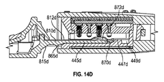
図14A〜Iは、図10E〜K及び11F〜Iそれぞれにおいて上述した、センサアセンブリレシーバと、センサアセンブリと、の間の相互作用を図示している。図14A〜Cは、センサアセンブリレシーバ400cの中に挿入されたときのセンサアセンブリ800cを図示している。図14A及びBは、センサアセンブリレシーバ400cの中へ徐々に挿入されているときのセンサアセンブリ800cの側部断面図を提供する。図14cは、センサアセンブリ800cの、センサアセンブリレシーバ400cの中へ部分的に挿入されるときの、頂面3分の2断面図を提供する。図14D〜Fは、センサアセンブリレシーバ400dの中へ挿入される際のセンサアセンブリ800dを図示している。図14D〜Eは、センサアセンブリ800dがセンサアセンブリレシーバ400dの中に徐々に挿入される際の、センサアセンブリ800dの側面断面図を提供する。図14Fは、センサアセンブリ800eの、部分的にセンサアセンブリレシーバ400eの中への挿入の際の頂面3分の2断面斜視図を提供する。図14G〜Iは、センサアセンブリレシーバ400eの中に挿入される際のセンサアセンブリ800eを図示する。図14G及びHは、センサアセンブリレシーバ400eの中に徐々に挿入される際のセンサアセンブリ800eの側面断面図を提供する。図14Iは、センサアセンブリ800cの、部分的にセンサアセンブリレシーバ400eの中への部分的な挿入の際の頂面3分の2斜視断面図を提供する。
14A-I illustrate the interaction between the sensor assembly receiver and sensor assembly described above in FIGS. 10E-K and 11F-I, respectively. 14A-C illustrate
動作中には、上述したように、いくつかの実施形態ではセンサアセンブリとセンサアセンブリレシーバとが相互作用して、センサアセンブリがセンサアセンブリレシーバに収容されるときにセンサアセンブリの頂面上の損耗を軽減することができる。図14Aに示されるように、センサアセンブリ800cはセンサアセンブリレシーバ400cの中に挿入されるので、センサタブ810cのセンサ面812cは、センサアセンブリレシーバ400cの中に下方に向かって延在する複数のポゴピン1000と相互作用することができる。複数のポゴピン1000のそれぞれはばねで留められ得るので、センサ面812cがポゴピン1000に近いほど、センサアセンブリ800cが挿入される際のセンサタブ810cのセンサ面812cにかかる圧力は大きくなる。いくつかの実施形態では、このことは、センサアセンブリ800c上のセンサの損耗を増加させる場合がある。いくつかの例では、図14A〜Bに図示されているように、センサタブ810cのセンサ面812c上の損耗は、センサアセンブリ800cが逆方向に動くためにセンサアセンブリレシーバ400cの底面443c上に2つのレベルを作ることによって軽減される。図14Aに図示されているように、センサアセンブリ800cがまずセンサアセンブリレシーバ400cの中に挿入されると、センサタブ810cが底面443cの近傍に移動する。いくつかの実施形態では、底面443cは、複数のポゴピン1000によってセンサ面812c上に生じる相互作用及び圧力を軽減するように構成される。次いで、図14Bに示されるように、センサアセンブリ800cのセンサタブ810cがセンサアセンブリ800cの中にさらに挿入されると、底面443cの傾斜した面441cが、センサタブ810cを高くされたレベルへ動くための傾斜路として作用する。いくつかの実施形態では、センサタブ810cは、これもまたセンサタブ810cを高くされたレベルへ動かすように作用することができる遠位端上の傾斜路815cをさらに含む。この高くされたレベルは、センサタブ810cを複数のポゴピン1000に対して近くにもたらし、それによってセンサアセンブリレシーバ400cとの電気的接続をより確実にする。いくつかの実施形態では、鍵戻り止め865c及び戻り止め440cが、使用者に機械的なフィードバックを提供するのに加えて、高くされた構成におけるセンサアセンブリ800cのセンサタブ810cをロックするように作用することができる。また、いくつかの例では、図14Cに示されるように、底部レセプタ876c及びセンサタブ810cの近位端870cに配置された底部突出部874cが、センサアセンブリレシーバ400cのレセプタ突出部447c及びレセプタ端部449cと相互作用して、センサアセンブリ800cをセンサアセンブリレシーバ400cに固定する。図14D〜F及び14G〜Iに図示されているように、センサアセンブリ800d及びセンサアセンブリレシーバ400d、並びにセンサアセンブリ800e及びセンサアセンブリレシーバ400eは上述したのと同様の、又は同じ態様で相互作用する。これら実施形態は、様々な実施形態におけるセンサタブのセンサ面上の損耗を軽減するという目標をさらに示す。図14A〜Cの符号付のルールは、“c”が“d”で置き換えられることを除いて図14D〜Fに適用され、“c”が“e”で置き換えられることを除いて図14G〜Iにも適用されている。
During operation, as described above, in some embodiments, the sensor assembly and sensor assembly receiver interact to reduce wear on the top surface of the sensor assembly when the sensor assembly is received in the sensor assembly receiver. Can be reduced. As shown in FIG. 14A, since the
上述したように、本設計の利点の1つは、広い範囲の電気接点を有する様々なセンサに適合するためのコネクタ及びセンサアセンブリの能力である。これは、ポゴピン1000及び表面上に複数の電気接点を有するセンサの使用を通じて達成される。より十分に後述されるように、コネクタ200が大量の電気接点に適合することができるので、コネクタ200中のポゴピン1000の構成は、短絡を防止することが重要である。
As mentioned above, one of the advantages of this design is the ability of the connector and sensor assembly to accommodate a variety of sensors having a wide range of electrical contacts. This is accomplished through the use of a
上述したように、センサアセンブリは様々なセンサに適合することができる。例えば、図11A〜11Cに示すように、センサアセンブリ800aは、センサに適合するとともにセンサを保持することができる頂部コネクタアセンブリ842a及び底部コネクタアセンブリ844aを有する。センサの近位端は、センサタブ810aのセンサ面812a上に配置されたセンサ上の複数の電気接点を有する。図12Aは、センサがセンサタブ上に配置された状態のセンサアセンブリ近位端900の例を図示する。センサアセンブリ近位端900は、センサタブ910及びリップ930を近位端上に有するコネクタアセンブリ970を含む。センサ940は、コネクタアセンブリ970の2つの部品間に、センサ940が頂部コネクタアセンブリ960の開口部990及びコネクタアセンブリ970の遠位端980の両方から突出するように保持される。センサ940の近位端はその表面に、複数のポゴピン1000のコンタクトチップ1170に係合するように構成された複数の電気接点(例えば、電気接点900a1、電気接点900b1、電気接点900c1、電気接点900c2、電気接点900d1、電気接点900d2、電気接点900e1、電気接点900f1、電気接点900g1、電気接点900g2)を有する。
As described above, the sensor assembly can be adapted to various sensors. For example, as shown in FIGS. 11A-11C, the
図12Aに見られるように、センサ940の面上のジグザグ状の電気接点が複数の列の形で配置されている。図12Aに示された例では、電気接点900a1は1つの列に、電気接点900b1は第2の列に、電気接点900c1及び電気接点900c2は第3の列に、電気接点900d1及び電気接点900d2は第4の列に、電気接点900e1は第5の列に、電気接点900f1は第6の列に、そしてセンサアセンブリ近位端900の電気接点g1及び電気接点900g2は第7の列にある。さらに以下に示されるように、複数のポゴピン1000は、内側シールド600中の同様な構成に配置されるとともに保持される。
As seen in FIG. 12A, zigzag electrical contacts on the surface of
図12Bは、センサアセンブリ近位端900の一実施形態を示し、複数のトレース950が接地トレース955を含む。図12Bに見られるように、接地トレース955(トレース950“3”と記載されている)は、センサタブの近位端からリップ930の近位端まで延在する。図12Cに図示するように、いくつかの実施形態では、接地トレース955bはセンサタブの表面上に完全に電気的に接続されている。他の実施形態では、図12Bに図示するように、接地トレース955は、センサの表面の下で電気的に接続されている部分を有する。他の実施形態では、接地トレース955はセンサの表面に亘って、間欠的に接続されている。
FIG. 12B illustrates one embodiment of the sensor assembly
いくつかの実施形態では、接地トレース955は、センサアセンブリの中の静電気のすべての集積を放電するための接地線として作用することができる。いくつかの実施形態では、コネクタ200又はセンサアセンブリへの損傷を防止するために、センサアセンブリは、所定の電気接続が複数のポゴピン1000と、トレース950(例えばいくつか又はすべてのトレース950)と、の間に形成される前に放電することができる。いくつかの例においては、複数のポゴピン1000のうちのいずれかが複数のトレース950のうちのいずれかに接続する前にセンサアセンブリを接地するために、コネクタの一部分が、すべての他のトレースの前に接地トレース955に接するように、接地トレース955を構成することができる。例えば、図12Bに図示するように、いくつかの実施形態では、接地トレース955は、同じ列にある他のトレースとは異なり、近位方向にさらに延在する。このように、センサアセンブリ近位端900のセンサ面920がコネクタ200の中に挿入されるので、コネクタ200内の構造は、接地トレース955に接触して、複数のポゴピン1000がセンサ面920上の残りのトレースに接する前に、センサアセンブリを最初に放電させる。
In some embodiments, the
センサアセンブリを接地するために、コネクタ200の一部分を接地することができる。いくつかの実施形態において、外側シールド300は接地線に接続される。他の実施形態では、内側シールド600は接地線に接続される。上述したように、いくつかの例では、センサアセンブリのセンサ面920に接触するように構成されているコネクタ200の一部分(例えば、外側シールド300又は内側シールド600)は、コネクタ200の設置された部分に接続される。いくつかの例では、複数のポゴピン1000のうちの1つは接地線に接続され、接地トレース955に接触するように構成することができる。他の例では、コネクタ200の内面は、所定の構造(例えば、突出部、柔軟なワイヤ又は接点のような伸長された要素)を、コネクタ200の他の導電性部分と接触する前に、センサアセンブリを接地するように接地トレース955に接触するように構成された接続の開口部の近傍に含む。
A portion of the
図13A及び図13Bは、対応するセンサアセンブリのセンサ上の電気接点に適合するポゴピン1000を有するコネクタの例を示す。図13Aに示されたセンサアセンブリ近位端1300は、センサ1340がそこから突出する開口部を有する頂部コネクタアセンブリ1320を有するコネクタアセンブリ1310を有する。センサ1340は、センサタブ上に含まれ、複数の電気接点1350を有する。図13Bは、複数の電気接点1350を有するコネクタ1400の断面図を示す。図13A及び13Bに示された例示のセンサアセンブリ及びコネクタにおいて、コネクタ1400におけるセンサ1340及びポゴピン1000上の電気接点の構成は、センサ1340とコネクタ1400との間に複数の電気接続を確立するように配置される。センサ1340は複数の電気接点(電気接点a、電気接点b1、電気接点b2、電気接点c1、電気接点c2、電気接点d1、電気接点d2、電気接点e1、電気接点e2、電気接点e3、電気接点e4、電気接点f1、電気接点f2、電気接点g1、及び電気接点g2)を有する。コネクタ1400は、複数のポゴピン1000(ポゴピン接点a’、ポゴピン接点b1’、ポゴピン接点b2’、ポゴピン接点c1’、ポゴピン接点c2’、ポゴピン接点d1’、ポゴピン接点d2’、ポゴピン接点e1’、ポゴピン接点e2’、ポゴピン接点e3’、ポゴピン接点e4’、ポゴピン接点f1’、ポゴピン接点f2’、ポゴピン接点g1’、ポゴピン接点g2’)を有する。これらポゴピン1000は、複数の電気接点に接触して、複数の電気接続を確立する。本例において、センサタブ1330が一旦、コネクタ1400の中に完全に挿入されると、以下のポゴピンが以下の電気接点に接触する:ポゴピン接点a’は電気接点aに接触し、ポゴピン接点b1’は電気接点b1に接触し、ポゴピン接点b2’は電気接点b2に接触し、ポゴピン接点c1’は電気接点c1に接触し、ポゴピン接点c2’は電気接点c2に接触し、ポゴピン接点d1’は電気接点d1に接触し、ポゴピン接点d2’は電気接点d2に接触し、ポゴピン接点e1’は電気接点e1に接触し、ポゴピン接点e2’は電気接点e2に接触し、ポゴピン接点e3’は電気接点e3に接触し、ポゴピン接点e4’は電気接点e4に接触し、ポゴピン接点f1’は電気接点f1に接触し、ポゴピン接点f2’は電気接点f2に接触し、ポゴピン接点g1’は電気接点g1に接触し、ポゴピン接点g2’は電気接点g2に接触する。
13A and 13B show examples of connectors having
センサタブ1330は、センサアセンブリレシーバ1420の開口部1410の中に挿入され、開口部1410に近接するポゴピン1000は、その対応する電気接点に接続する前に、センサ1340の長さに接触する。例えば、ポゴピン接点a1’は、電気接点aに到達する前に、センサ1340の近位端に接触する。したがって一構成では、短絡を防止するために、センサ1340上の電気接点と、対応するコネクタ1400のポゴピン1000と、がジグザグ状の列に配置されて、ポゴピン1000のそれぞれの近位端が、センサタブ1330がコネクタ1400の中に挿入される際に接触する電気接点を最小化する。例えば、図13Aに見られるように、電気接点b1は、電気接点aと、電気接点c1と、に近接し、かつそれらの間に配置される。このように、ポゴピン接点b1’の両側のポゴピン接点a1’及びポゴピン接点c1’は、センサタブ1330が挿入されるときに電気接点b1に接触することはない。
The
センサタブ1330上の電気接点及びコネクタ1400内のポゴピン1000のジグザグ状の配置の別の一の可能性のある利点は、センサがコネクタ1400のセンサタブ1330と内側シールド600とから成る構成を与えられ得る電気接続の増加である。すでに述べたように、ポゴピン1000及びセンサタブ1330上の電気接点の構成の故に、開示されたセンサアセンブリ及びコネクタの構成は、大量の電気接点を必要とするセンサに適合することができる。
Another possible advantage of the zigzag arrangement of the electrical contacts on the
この開示は、所定の好ましい実施形態及び例示の内容に開示されているが、当業者であれは、本開示が特定的に開示された実施形態を超えて、他の代替実施形態及び/又は開示の使用および明らかな変形及びその同等物にも拡張されることを理解するだろう。さらに、本開示の多くの変形が詳細に示され、記載されてきたが、これらはこの開示の範囲内にあり、当業者にはこの開示に基づいて容易に明白であろう。また、特定の特徴と実施形態の特徴との様々な組み合わせ、又は下位の組み合わせを行うことができ、それらは本開示の技術的範囲内に依然として入る。したがって、開示された実施形態の様々な特徴は、組み合わせること又は互いに置き換えることができ、それによって開示されたものの変化した形を形成する。 While this disclosure is disclosed in terms of certain preferred embodiments and examples, those skilled in the art will appreciate that other alternative embodiments and / or disclosures are beyond the specifically disclosed embodiments of this disclosure. Will be understood to extend to the use of and obvious variations and equivalents thereof. Moreover, while many variations of the present disclosure have been shown and described in detail, they are within the scope of this disclosure and will be readily apparent to those skilled in the art based on this disclosure. Also, various combinations or sub-combinations of particular features with the features of the embodiments can be made and still fall within the scope of the present disclosure. Accordingly, the various features of the disclosed embodiments can be combined or replaced with one another, thereby forming a varied form of what is disclosed.
Claims (111)
前記アセンブリが、
内面を有する開口部;及び
前記内面から延びる複数の伸縮自在な電気コネクタ
を含むコネクタと、
本体部分;及び
複数の電気接点を含む頂面を有する近位端であって、該近位端が前記コネクタの前記
開口部の中に取り外し可能に挿入されるように構成されている、近位端
を含むセンサアセンブリと、
を含む、コネクタ及びセンサアセンブリ。 A connector and sensor assembly comprising:
The assembly is
An connector having an inner surface; and a plurality of telescopic electrical connectors extending from the inner surface;
A proximal end having a top surface including a body portion; and a plurality of electrical contacts, the proximal end configured to be removably inserted into the opening of the connector A sensor assembly including an end; and
A connector and sensor assembly.
前記第1のテーパを付けられた面は前記コネクタの前記開口部の中に向かって先細とされ、前記第2のテーパを付けられた面は、外側に向かって先細とされていることを特徴とする請求項1〜8のいずれか一項に記載のコネクタ及びセンサアセンブリ。 Further comprising a first tapered surface at the proximal end of the connector and a second tapered surface at the proximal end of the sensor assembly;
The first tapered surface tapers into the opening of the connector and the second tapered surface tapers outward. The connector and sensor assembly according to any one of claims 1 to 8.
前記テーパをかけられた面は、前記センサアセンブリの前記面上の前記複数の電気接点の損耗を軽減するように構成されていることを特徴とする請求項9に記載のコネクタ及びセンサアセンブリ。 The tapered surface of the sensor assembly is configured to lift each of the plurality of telescopic electrical connectors when the sensor assembly is inserted into the opening of the connector. And
The connector and sensor assembly of claim 9, wherein the tapered surface is configured to reduce wear of the plurality of electrical contacts on the surface of the sensor assembly.
前記アセンブリが、
第1の面を有する開口部を含むコネクタであって、前記第1の面がロック構造を含むコネクタと、
本体部分;及び
前記コネクタの前記ロック構造の中にぴったり合うように構成された鍵構造を含む近
位端であって、前記近位端は、前記コネクタの前記開口部の中に取り外し可能に挿入さ
れるように構成されている、近位端
を含むセンサアセンブリと、
を含む、コネクタ及びセンサアセンブリ。 A connector and sensor assembly comprising:
The assembly is
A connector including an opening having a first surface, wherein the first surface includes a lock structure;
A proximal end comprising a body portion; and a key structure configured to fit snugly within the locking structure of the connector, the proximal end removably inserted into the opening of the connector A sensor assembly including a proximal end configured to be configured with:
A connector and sensor assembly.
前記テーパを付けられた面は、前記センサアセンブリの前記面上の前記複数の電気接点の損耗を軽減するように構成されていることを特徴とする請求項23に記載のコネクタ及びセンサアセンブリ。 The tapered surface of the sensor assembly is configured to lift each of a plurality of telescopic electrical connectors as the sensor assembly is inserted into the opening of the connector;
24. The connector and sensor assembly of claim 23, wherein the tapered surface is configured to reduce wear of the plurality of electrical contacts on the surface of the sensor assembly.
前記アセンブリが、
第1の面と第2の面とを有する開口部であって、前記第1の面と前記第2の面とが互
いに対向する、開口部;
前記第1の面及び前記第2の面のうちの一方から延在する伸縮自在な複数の電気コネ
クタ;及び
前記第1の面及び前記第2の面のうちの一方上のロック構造
を有するコネクタと、
前記コネクタの前記ロック構造の中にぴったり合うように構成された複数の電気接点
及び鍵構造を含む本体部分であって、該本体部分が前記コネクタの前記開口部の中に取
り外し可能に挿入されるように構成されている、本体部分
を含む、センサアセンブリと、
を含む、コネクタ及びセンサアセンブリ。 A connector and sensor assembly comprising:
The assembly is
An opening having a first surface and a second surface, wherein the first surface and the second surface oppose each other;
A plurality of telescopic electrical connectors extending from one of the first surface and the second surface; and a locking structure on one of the first surface and the second surface. A connector;
A body portion including a plurality of electrical contacts and a key structure configured to fit snugly within the locking structure of the connector, wherein the body portion is removably inserted into the opening of the connector. A sensor assembly including a body portion configured to be
A connector and sensor assembly.
前記第1のテーパを付けられた面は前記コネクタの開口部の中に向かって先細とされ、前記第2のテーパを付けられた面は、外側に向かって先細とされていることを特徴とする請求項35〜42のいずれか一項に記載のコネクタ及びセンサアセンブリ。 Further comprising a first tapered surface on the proximal end of the connector and a second tapered surface on the proximal end of the sensor assembly;
The first tapered surface is tapered toward the connector opening, and the second tapered surface is tapered outward. 43. The connector and sensor assembly according to any one of claims 35 to 42.
前記テーパをかけられた面は、前記センサアセンブリの前記面上の前記複数の電気接点の損耗を軽減するように構成されていることを特徴とする請求項43に記載のコネクタ及びセンサアセンブリ。 The tapered surface of the sensor assembly is configured to lift each of the telescopic electrical connectors when the sensor assembly is inserted into the opening of the connector. And
44. The connector and sensor assembly of claim 43, wherein the tapered surface is configured to reduce wear of the plurality of electrical contacts on the surface of the sensor assembly.
前記アセンブリが、
第1の面と第2の面とを有する開口部であって、前記第1の面及び前記第2の面が互
いに対向し、前記第2の面が傾斜した傾斜路によって接続される第1の面と第2の面と
を含む、開口部;
前記第1の面から延在する複数の伸縮自在な電気コネクタ;及び
前記第2の面に配置されたロック構造;
を備えるコネクタと、
本体部分;及び
頂面及び底面を含む近位端であって、
前記頂面が複数の電気接点を備え、前記底面が前記コネクタの前記ロック構造の中に
ぴったり合うように構成された鍵構造を備え、
前記近位端が前記コネクタの前記開口部の中に取り外し可能に挿入されるように構成
されている、近位端
を含むセンサアセンブリと、
を含む、コネクタ及びセンサアセンブリ。 A connector and sensor assembly comprising:
The assembly is
An opening having a first surface and a second surface, wherein the first surface and the second surface are opposed to each other, and the second surface is connected by an inclined slope. An opening comprising a first surface and a second surface;
A plurality of telescopic electrical connectors extending from the first surface; and a locking structure disposed on the second surface;
A connector comprising:
A proximal end including a body portion; and a top surface and a bottom surface,
The top surface includes a plurality of electrical contacts and the bottom surface includes a key structure configured to fit snugly within the locking structure of the connector;
A sensor assembly including a proximal end, wherein the proximal end is configured to be removably inserted into the opening of the connector;
A connector and sensor assembly.
前記第1のテーパを付けられた面は前記コネクタの前記開口部の中に向かって先細とされ、前記第2のテーパを付けられた面は、外側に向かって先細とされていることを特徴とする請求項61〜68のいずれか一項に記載のコネクタ及びセンサアセンブリ。 Further comprising: a first tapered surface on the proximal end of the connector; and a second tapered surface on the proximal end of the sensor assembly;
The first tapered surface tapers into the opening of the connector and the second tapered surface tapers outward. 69. The connector and sensor assembly according to any one of claims 61 to 68.
前記テーパをかけられた面は、前記センサアセンブリの前記面上の前記複数の電気接点の損耗を軽減するように構成されていることを特徴とする請求項70に記載のコネクタ及びセンサアセンブリ。 The tapered surface of the sensor assembly is configured to lift each of the plurality of telescopic electrical connectors when the sensor assembly is inserted into the opening of the connector. And
The connector and sensor assembly of claim 70, wherein the tapered surface is configured to reduce wear of the plurality of electrical contacts on the surface of the sensor assembly.
前記雄コネクタは、
平坦な板部分と、
前記平坦な板部分上にジグザグ状の構成に配置された複数の電気接点であって、前記
電気接点の少なくとも1つは接地接点であり、前記接地接点は物理的に接触するように
配置されるとともに、他のいずれかの接点が前記雌コネクタの対応する接点と電気的な
連通状態になる前に、対応する雌コネクタの電気接点と電気的に連通する、複数の電気
接点と、
を備える、雄コネクタアセンブリ。 A male connector assembly connected to and in electrical communication with a corresponding female connector;
The male connector is
A flat plate part,
A plurality of electrical contacts disposed in a zigzag configuration on the flat plate portion, wherein at least one of the electrical contacts is a ground contact, and the ground contact is disposed in physical contact. And a plurality of electrical contacts that are in electrical communication with the electrical contacts of the corresponding female connector before any other contact is in electrical communication with the corresponding contact of the female connector;
A male connector assembly comprising:
前記雌コネクタは、
内面を有する本体部分と、
前記内面上にジグザグ状の構成に配置された複数の伸縮自在な電気コネクタであって
、前記複数の伸縮自在な電気コネクタは、対応する雄コネクタの電気接点と物理的に接
触するとともに電気的に連通するように構成されている、複数の伸縮自在な電気コネク
タと、
を備える、雌コネクタアセンブリ。 A female connector assembly that is physically connected to and in electrical communication with a corresponding male connector;
The female connector is
A body portion having an inner surface;
A plurality of telescopic electrical connectors disposed in a zigzag configuration on the inner surface, wherein the plurality of telescopic electrical connectors are in physical contact with electrical contacts of corresponding male connectors and are electrically A plurality of telescopic electrical connectors configured to communicate with the
A female connector assembly comprising:
Applications Claiming Priority (5)
| Application Number | Priority Date | Filing Date | Title |
|---|---|---|---|
| US201562113054P | 2015-02-06 | 2015-02-06 | |
| US62/113,054 | 2015-02-06 | ||
| US201562152733P | 2015-04-24 | 2015-04-24 | |
| US62/152,733 | 2015-04-24 | ||
| PCT/US2016/016883 WO2016127125A1 (en) | 2015-02-06 | 2016-02-05 | Connector assembly with pogo pins for use with medical sensors |
Publications (3)
| Publication Number | Publication Date |
|---|---|
| JP2018506154A true JP2018506154A (en) | 2018-03-01 |
| JP2018506154A5 JP2018506154A5 (en) | 2019-03-22 |
| JP6808631B2 JP6808631B2 (en) | 2021-01-06 |
Family
ID=55410260
Family Applications (1)
| Application Number | Title | Priority Date | Filing Date |
|---|---|---|---|
| JP2017541361A Active JP6808631B2 (en) | 2015-02-06 | 2016-02-05 | Combination of connector and sensor assembly |
Country Status (10)
| Country | Link |
|---|---|
| US (7) | US10205291B2 (en) |
| EP (1) | EP3254339B1 (en) |
| JP (1) | JP6808631B2 (en) |
| KR (3) | KR102594704B1 (en) |
| CN (2) | CN107431301B (en) |
| AU (1) | AU2016215025B2 (en) |
| BR (1) | BR112017016308B1 (en) |
| CA (1) | CA2974832C (en) |
| MX (1) | MX374905B (en) |
| WO (1) | WO2016127125A1 (en) |
Families Citing this family (292)
| Publication number | Priority date | Publication date | Assignee | Title |
|---|---|---|---|---|
| WO1999062399A1 (en) | 1998-06-03 | 1999-12-09 | Masimo Corporation | Stereo pulse oximeter |
| US6684090B2 (en) | 1999-01-07 | 2004-01-27 | Masimo Corporation | Pulse oximetry data confidence indicator |
| WO2002015781A1 (en) | 2000-08-18 | 2002-02-28 | Masimo Corporation | Dual-mode pulse oximeter |
| US6850787B2 (en) | 2001-06-29 | 2005-02-01 | Masimo Laboratories, Inc. | Signal component processor |
| US6697658B2 (en) | 2001-07-02 | 2004-02-24 | Masimo Corporation | Low power pulse oximeter |
| US7355512B1 (en) | 2002-01-24 | 2008-04-08 | Masimo Corporation | Parallel alarm processor |
| US6850788B2 (en) | 2002-03-25 | 2005-02-01 | Masimo Corporation | Physiological measurement communications adapter |
| US6920345B2 (en) | 2003-01-24 | 2005-07-19 | Masimo Corporation | Optical sensor including disposable and reusable elements |
| US7003338B2 (en) | 2003-07-08 | 2006-02-21 | Masimo Corporation | Method and apparatus for reducing coupling between signals |
| US7500950B2 (en) | 2003-07-25 | 2009-03-10 | Masimo Corporation | Multipurpose sensor port |
| US7483729B2 (en) | 2003-11-05 | 2009-01-27 | Masimo Corporation | Pulse oximeter access apparatus and method |
| US7415297B2 (en) | 2004-03-08 | 2008-08-19 | Masimo Corporation | Physiological parameter system |
| JP5328159B2 (en) | 2005-03-01 | 2013-10-30 | セルカコア・ラボラトリーズ・インコーポレーテッド | Multi-wavelength sensor light emitter |
| CA2604653A1 (en) | 2005-04-13 | 2006-10-19 | Glucolight Corporation | Method for data reduction and calibration of an oct-based blood glucose monitor |
| US12014328B2 (en) | 2005-07-13 | 2024-06-18 | Vccb Holdings, Inc. | Medicine bottle cap with electronic embedded curved display |
| US7962188B2 (en) | 2005-10-14 | 2011-06-14 | Masimo Corporation | Robust alarm system |
| US8182443B1 (en) | 2006-01-17 | 2012-05-22 | Masimo Corporation | Drug administration controller |
| US8219172B2 (en) | 2006-03-17 | 2012-07-10 | Glt Acquisition Corp. | System and method for creating a stable optical interface |
| US7941199B2 (en) | 2006-05-15 | 2011-05-10 | Masimo Laboratories, Inc. | Sepsis monitor |
| US10188348B2 (en) | 2006-06-05 | 2019-01-29 | Masimo Corporation | Parameter upgrade system |
| US8457707B2 (en) | 2006-09-20 | 2013-06-04 | Masimo Corporation | Congenital heart disease monitor |
| US8840549B2 (en) | 2006-09-22 | 2014-09-23 | Masimo Corporation | Modular patient monitor |
| US9861305B1 (en) | 2006-10-12 | 2018-01-09 | Masimo Corporation | Method and apparatus for calibration to reduce coupling between signals in a measurement system |
| US8255026B1 (en) | 2006-10-12 | 2012-08-28 | Masimo Corporation, Inc. | Patient monitor capable of monitoring the quality of attached probes and accessories |
| US7880626B2 (en) | 2006-10-12 | 2011-02-01 | Masimo Corporation | System and method for monitoring the life of a physiological sensor |
| US8280473B2 (en) | 2006-10-12 | 2012-10-02 | Masino Corporation, Inc. | Perfusion index smoother |
| US8265723B1 (en) | 2006-10-12 | 2012-09-11 | Cercacor Laboratories, Inc. | Oximeter probe off indicator defining probe off space |
| US9192329B2 (en) | 2006-10-12 | 2015-11-24 | Masimo Corporation | Variable mode pulse indicator |
| US8600467B2 (en) | 2006-11-29 | 2013-12-03 | Cercacor Laboratories, Inc. | Optical sensor including disposable and reusable elements |
| EP2096994B1 (en) | 2006-12-09 | 2018-10-03 | Masimo Corporation | Plethysmograph variability determination |
| US8852094B2 (en) | 2006-12-22 | 2014-10-07 | Masimo Corporation | Physiological parameter system |
| US8652060B2 (en) | 2007-01-20 | 2014-02-18 | Masimo Corporation | Perfusion trend indicator |
| US8374665B2 (en) | 2007-04-21 | 2013-02-12 | Cercacor Laboratories, Inc. | Tissue profile wellness monitor |
| US8768423B2 (en) | 2008-03-04 | 2014-07-01 | Glt Acquisition Corp. | Multispot monitoring for use in optical coherence tomography |
| EP2278911A1 (en) | 2008-05-02 | 2011-02-02 | Masimo Corporation | Monitor configuration system |
| EP2312995B1 (en) | 2008-05-05 | 2017-06-28 | Masimo Corporation | Pulse oximetry system with electrical decoupling circuitry |
| US20100004518A1 (en) | 2008-07-03 | 2010-01-07 | Masimo Laboratories, Inc. | Heat sink for noninvasive medical sensor |
| US8203438B2 (en) | 2008-07-29 | 2012-06-19 | Masimo Corporation | Alarm suspend system |
| US8630691B2 (en) | 2008-08-04 | 2014-01-14 | Cercacor Laboratories, Inc. | Multi-stream sensor front ends for noninvasive measurement of blood constituents |
| SE532941C2 (en) | 2008-09-15 | 2010-05-18 | Phasein Ab | Gas sampling line for breathing gases |
| US8771204B2 (en) | 2008-12-30 | 2014-07-08 | Masimo Corporation | Acoustic sensor assembly |
| US8588880B2 (en) | 2009-02-16 | 2013-11-19 | Masimo Corporation | Ear sensor |
| WO2010102069A2 (en) | 2009-03-04 | 2010-09-10 | Masimo Corporation | Medical monitoring system |
| US10007758B2 (en) | 2009-03-04 | 2018-06-26 | Masimo Corporation | Medical monitoring system |
| US10032002B2 (en) | 2009-03-04 | 2018-07-24 | Masimo Corporation | Medical monitoring system |
| US9323894B2 (en) | 2011-08-19 | 2016-04-26 | Masimo Corporation | Health care sanitation monitoring system |
| US8388353B2 (en) | 2009-03-11 | 2013-03-05 | Cercacor Laboratories, Inc. | Magnetic connector |
| US8989831B2 (en) | 2009-05-19 | 2015-03-24 | Masimo Corporation | Disposable components for reusable physiological sensor |
| US8571619B2 (en) | 2009-05-20 | 2013-10-29 | Masimo Corporation | Hemoglobin display and patient treatment |
| US20110208015A1 (en) | 2009-07-20 | 2011-08-25 | Masimo Corporation | Wireless patient monitoring system |
| US8473020B2 (en) | 2009-07-29 | 2013-06-25 | Cercacor Laboratories, Inc. | Non-invasive physiological sensor cover |
| US9579039B2 (en) | 2011-01-10 | 2017-02-28 | Masimo Corporation | Non-invasive intravascular volume index monitor |
| US20110137297A1 (en) | 2009-09-17 | 2011-06-09 | Kiani Massi Joe E | Pharmacological management system |
| US20110082711A1 (en) | 2009-10-06 | 2011-04-07 | Masimo Laboratories, Inc. | Personal digital assistant or organizer for monitoring glucose levels |
| US8821415B2 (en) | 2009-10-15 | 2014-09-02 | Masimo Corporation | Physiological acoustic monitoring system |
| US9066680B1 (en) | 2009-10-15 | 2015-06-30 | Masimo Corporation | System for determining confidence in respiratory rate measurements |
| WO2011047216A2 (en) | 2009-10-15 | 2011-04-21 | Masimo Corporation | Physiological acoustic monitoring system |
| US8702627B2 (en) | 2009-10-15 | 2014-04-22 | Masimo Corporation | Acoustic respiratory monitoring sensor having multiple sensing elements |
| US8790268B2 (en) | 2009-10-15 | 2014-07-29 | Masimo Corporation | Bidirectional physiological information display |
| US9724016B1 (en) | 2009-10-16 | 2017-08-08 | Masimo Corp. | Respiration processor |
| US9839381B1 (en) | 2009-11-24 | 2017-12-12 | Cercacor Laboratories, Inc. | Physiological measurement system with automatic wavelength adjustment |
| GB2487882B (en) | 2009-12-04 | 2017-03-29 | Masimo Corp | Calibration for multi-stage physiological monitors |
| US9153112B1 (en) | 2009-12-21 | 2015-10-06 | Masimo Corporation | Modular patient monitor |
| DE112011100282T5 (en) | 2010-01-19 | 2012-11-29 | Masimo Corporation | Wellness assessment system |
| WO2011109312A2 (en) | 2010-03-01 | 2011-09-09 | Masimo Corporation | Adaptive alarm system |
| EP2544591B1 (en) | 2010-03-08 | 2021-07-21 | Masimo Corporation | Reprocessing of a physiological sensor |
| US9307928B1 (en) | 2010-03-30 | 2016-04-12 | Masimo Corporation | Plethysmographic respiration processor |
| US9138180B1 (en) | 2010-05-03 | 2015-09-22 | Masimo Corporation | Sensor adapter cable |
| US8666468B1 (en) | 2010-05-06 | 2014-03-04 | Masimo Corporation | Patient monitor for determining microcirculation state |
| US9408542B1 (en) | 2010-07-22 | 2016-08-09 | Masimo Corporation | Non-invasive blood pressure measurement system |
| WO2012050847A2 (en) | 2010-09-28 | 2012-04-19 | Masimo Corporation | Depth of consciousness monitor including oximeter |
| US9775545B2 (en) | 2010-09-28 | 2017-10-03 | Masimo Corporation | Magnetic electrical connector for patient monitors |
| US12198790B1 (en) | 2010-10-07 | 2025-01-14 | Masimo Corporation | Physiological monitor sensor systems and methods |
| US9211095B1 (en) | 2010-10-13 | 2015-12-15 | Masimo Corporation | Physiological measurement logic engine |
| US20120226117A1 (en) | 2010-12-01 | 2012-09-06 | Lamego Marcelo M | Handheld processing device including medical applications for minimally and non invasive glucose measurements |
| EP2673721A1 (en) | 2011-02-13 | 2013-12-18 | Masimo Corporation | Medical characterization system |
| US9066666B2 (en) | 2011-02-25 | 2015-06-30 | Cercacor Laboratories, Inc. | Patient monitor for monitoring microcirculation |
| US9986919B2 (en) | 2011-06-21 | 2018-06-05 | Masimo Corporation | Patient monitoring system |
| US9532722B2 (en) | 2011-06-21 | 2017-01-03 | Masimo Corporation | Patient monitoring system |
| US11439329B2 (en) | 2011-07-13 | 2022-09-13 | Masimo Corporation | Multiple measurement mode in a physiological sensor |
| US9782077B2 (en) | 2011-08-17 | 2017-10-10 | Masimo Corporation | Modulated physiological sensor |
| US9436645B2 (en) | 2011-10-13 | 2016-09-06 | Masimo Corporation | Medical monitoring hub |
| US9808188B1 (en) | 2011-10-13 | 2017-11-07 | Masimo Corporation | Robust fractional saturation determination |
| EP3603502B1 (en) | 2011-10-13 | 2023-10-04 | Masimo Corporation | Physiological acoustic monitoring system |
| US9943269B2 (en) | 2011-10-13 | 2018-04-17 | Masimo Corporation | System for displaying medical monitoring data |
| US9778079B1 (en) | 2011-10-27 | 2017-10-03 | Masimo Corporation | Physiological monitor gauge panel |
| US12004881B2 (en) | 2012-01-04 | 2024-06-11 | Masimo Corporation | Automated condition screening and detection |
| US9392945B2 (en) | 2012-01-04 | 2016-07-19 | Masimo Corporation | Automated CCHD screening and detection |
| US11172890B2 (en) | 2012-01-04 | 2021-11-16 | Masimo Corporation | Automated condition screening and detection |
| US9267572B2 (en) | 2012-02-08 | 2016-02-23 | Masimo Corporation | Cable tether system |
| US10149616B2 (en) | 2012-02-09 | 2018-12-11 | Masimo Corporation | Wireless patient monitoring device |
| GB2541301B (en) * | 2012-03-15 | 2017-07-12 | Fisher & Paykel Healthcare Ltd | Respiratory gas humidification system |
| EP2845086B1 (en) | 2012-03-25 | 2021-12-22 | Masimo Corporation | Physiological monitor touchscreen interface |
| US9131881B2 (en) | 2012-04-17 | 2015-09-15 | Masimo Corporation | Hypersaturation index |
| GB2577634B (en) | 2012-04-27 | 2020-09-30 | Fisher & Paykel Healthcare Ltd | Respiratory humidification apparatus |
| WO2013184965A1 (en) | 2012-06-07 | 2013-12-12 | Masimo Corporation | Depth of consciousness monitor |
| US9697928B2 (en) | 2012-08-01 | 2017-07-04 | Masimo Corporation | Automated assembly sensor cable |
| US10827961B1 (en) | 2012-08-29 | 2020-11-10 | Masimo Corporation | Physiological measurement calibration |
| US9877650B2 (en) | 2012-09-20 | 2018-01-30 | Masimo Corporation | Physiological monitor with mobile computing device connectivity |
| US9749232B2 (en) | 2012-09-20 | 2017-08-29 | Masimo Corporation | Intelligent medical network edge router |
| US9955937B2 (en) | 2012-09-20 | 2018-05-01 | Masimo Corporation | Acoustic patient sensor coupler |
| US9717458B2 (en) | 2012-10-20 | 2017-08-01 | Masimo Corporation | Magnetic-flap optical sensor |
| US9560996B2 (en) | 2012-10-30 | 2017-02-07 | Masimo Corporation | Universal medical system |
| US9787568B2 (en) | 2012-11-05 | 2017-10-10 | Cercacor Laboratories, Inc. | Physiological test credit method |
| US9750461B1 (en) | 2013-01-02 | 2017-09-05 | Masimo Corporation | Acoustic respiratory monitoring sensor with probe-off detection |
| US9724025B1 (en) | 2013-01-16 | 2017-08-08 | Masimo Corporation | Active-pulse blood analysis system |
| US10441181B1 (en) | 2013-03-13 | 2019-10-15 | Masimo Corporation | Acoustic pulse and respiration monitoring system |
| US9965946B2 (en) | 2013-03-13 | 2018-05-08 | Masimo Corporation | Systems and methods for monitoring a patient health network |
| US9936917B2 (en) | 2013-03-14 | 2018-04-10 | Masimo Laboratories, Inc. | Patient monitor placement indicator |
| US10456038B2 (en) | 2013-03-15 | 2019-10-29 | Cercacor Laboratories, Inc. | Cloud-based physiological monitoring system |
| US12178572B1 (en) | 2013-06-11 | 2024-12-31 | Masimo Corporation | Blood glucose sensing system |
| US9891079B2 (en) | 2013-07-17 | 2018-02-13 | Masimo Corporation | Pulser with double-bearing position encoder for non-invasive physiological monitoring |
| WO2015020911A2 (en) | 2013-08-05 | 2015-02-12 | Cercacor Laboratories, Inc. | Blood pressure monitor with valve-chamber assembly |
| US12367973B2 (en) | 2013-09-12 | 2025-07-22 | Willow Laboratories, Inc. | Medical device calibration |
| WO2015038683A2 (en) | 2013-09-12 | 2015-03-19 | Cercacor Laboratories, Inc. | Medical device management system |
| GB2583046B8 (en) | 2013-09-13 | 2021-04-28 | Fisher & Paykel Healthcare Ltd | Resilient probe mount for a humidification system |
| US11147518B1 (en) | 2013-10-07 | 2021-10-19 | Masimo Corporation | Regional oximetry signal processor |
| US10010276B2 (en) | 2013-10-07 | 2018-07-03 | Masimo Corporation | Regional oximetry user interface |
| US10832818B2 (en) | 2013-10-11 | 2020-11-10 | Masimo Corporation | Alarm notification system |
| US10828007B1 (en) | 2013-10-11 | 2020-11-10 | Masimo Corporation | Acoustic sensor with attachment portion |
| US10279247B2 (en) | 2013-12-13 | 2019-05-07 | Masimo Corporation | Avatar-incentive healthcare therapy |
| US11259745B2 (en) | 2014-01-28 | 2022-03-01 | Masimo Corporation | Autonomous drug delivery system |
| US10086138B1 (en) | 2014-01-28 | 2018-10-02 | Masimo Corporation | Autonomous drug delivery system |
| US10449319B2 (en) | 2014-02-07 | 2019-10-22 | Fisher & Paykel Healthcare Limited | Respiratory humidification system |
| US10123729B2 (en) | 2014-06-13 | 2018-11-13 | Nanthealth, Inc. | Alarm fatigue management systems and methods |
| US10231670B2 (en) | 2014-06-19 | 2019-03-19 | Masimo Corporation | Proximity sensor in pulse oximeter |
| US10111591B2 (en) | 2014-08-26 | 2018-10-30 | Nanthealth, Inc. | Real-time monitoring systems and methods in a healthcare environment |
| US10231657B2 (en) | 2014-09-04 | 2019-03-19 | Masimo Corporation | Total hemoglobin screening sensor |
| US10383520B2 (en) | 2014-09-18 | 2019-08-20 | Masimo Semiconductor, Inc. | Enhanced visible near-infrared photodiode and non-invasive physiological sensor |
| US10154815B2 (en) | 2014-10-07 | 2018-12-18 | Masimo Corporation | Modular physiological sensors |
| AU2016209104B2 (en) | 2015-01-23 | 2020-04-30 | Masimo Sweden Ab | Nasal/oral cannula system and manufacturing |
| BR112017016308B1 (en) | 2015-02-06 | 2023-04-11 | Masimo Corporation | CONNECTOR AND SENSOR ASSEMBLY |
| US10568553B2 (en) | 2015-02-06 | 2020-02-25 | Masimo Corporation | Soft boot pulse oximetry sensor |
| US10327337B2 (en) | 2015-02-06 | 2019-06-18 | Masimo Corporation | Fold flex circuit for LNOP |
| US10524738B2 (en) | 2015-05-04 | 2020-01-07 | Cercacor Laboratories, Inc. | Noninvasive sensor system with visual infographic display |
| US11653862B2 (en) | 2015-05-22 | 2023-05-23 | Cercacor Laboratories, Inc. | Non-invasive optical physiological differential pathlength sensor |
| USD765030S1 (en) * | 2015-06-02 | 2016-08-30 | Johnson Controls Technology Company | Low voltage connector barrel for lithium ion battery module |
| US10448871B2 (en) | 2015-07-02 | 2019-10-22 | Masimo Corporation | Advanced pulse oximetry sensor |
| KR102659974B1 (en) * | 2015-07-06 | 2024-04-22 | 엘리멘탈 사이언티픽, 인코포레이티드 | Mounting structures and components of interchangeable, visually marked sample introduction systems for inductively coupled plasma systems |
| AU2016304884B2 (en) | 2015-08-11 | 2021-01-28 | Masimo Corporation | Medical monitoring analysis and replay including indicia responsive to light attenuated by body tissue |
| AU2016315947B2 (en) | 2015-08-31 | 2021-02-18 | Masimo Corporation | Wireless patient monitoring systems and methods |
| US11504066B1 (en) | 2015-09-04 | 2022-11-22 | Cercacor Laboratories, Inc. | Low-noise sensor system |
| US11679579B2 (en) | 2015-12-17 | 2023-06-20 | Masimo Corporation | Varnish-coated release liner |
| US10471159B1 (en) | 2016-02-12 | 2019-11-12 | Masimo Corporation | Diagnosis, removal, or mechanical damaging of tumor using plasmonic nanobubbles |
| US10993662B2 (en) | 2016-03-04 | 2021-05-04 | Masimo Corporation | Nose sensor |
| US10537285B2 (en) | 2016-03-04 | 2020-01-21 | Masimo Corporation | Nose sensor |
| US11191484B2 (en) | 2016-04-29 | 2021-12-07 | Masimo Corporation | Optical sensor tape |
| WO2018009612A1 (en) | 2016-07-06 | 2018-01-11 | Patient Doctor Technologies, Inc. | Secure and zero knowledge data sharing for cloud applications |
| US10617302B2 (en) | 2016-07-07 | 2020-04-14 | Masimo Corporation | Wearable pulse oximeter and respiration monitor |
| USD867993S1 (en) * | 2016-09-02 | 2019-11-26 | Cps Technology Holdings Llc | Battery module connector barrel |
| US11076777B2 (en) | 2016-10-13 | 2021-08-03 | Masimo Corporation | Systems and methods for monitoring orientation to reduce pressure ulcer formation |
| GB2557199B (en) | 2016-11-30 | 2020-11-04 | Lidco Group Plc | Haemodynamic monitor with improved filtering |
| US11504058B1 (en) | 2016-12-02 | 2022-11-22 | Masimo Corporation | Multi-site noninvasive measurement of a physiological parameter |
| SG10202106016TA (en) | 2016-12-07 | 2021-07-29 | Fisher and paykel healthcare ltd | Sensing arrangements for medical devices |
| US10750984B2 (en) | 2016-12-22 | 2020-08-25 | Cercacor Laboratories, Inc. | Methods and devices for detecting intensity of light with translucent detector |
| US10721785B2 (en) | 2017-01-18 | 2020-07-21 | Masimo Corporation | Patient-worn wireless physiological sensor with pairing functionality |
| WO2018156648A1 (en) | 2017-02-24 | 2018-08-30 | Masimo Corporation | Managing dynamic licenses for physiological parameters in a patient monitoring environment |
| WO2018156809A1 (en) | 2017-02-24 | 2018-08-30 | Masimo Corporation | Augmented reality system for displaying patient data |
| EP3585254B1 (en) | 2017-02-24 | 2024-03-20 | Masimo Corporation | Medical device cable and method of sharing data between connected medical devices |
| US10388120B2 (en) | 2017-02-24 | 2019-08-20 | Masimo Corporation | Localized projection of audible noises in medical settings |
| US11086609B2 (en) | 2017-02-24 | 2021-08-10 | Masimo Corporation | Medical monitoring hub |
| US10327713B2 (en) | 2017-02-24 | 2019-06-25 | Masimo Corporation | Modular multi-parameter patient monitoring device |
| WO2018165618A1 (en) | 2017-03-10 | 2018-09-13 | Masimo Corporation | Pneumonia screener |
| WO2018194992A1 (en) | 2017-04-18 | 2018-10-25 | Masimo Corporation | Nose sensor |
| US10918281B2 (en) | 2017-04-26 | 2021-02-16 | Masimo Corporation | Medical monitoring device having multiple configurations |
| EP4368104A3 (en) | 2017-04-28 | 2024-09-25 | Masimo Corporation | Spot check measurement system |
| USD835283S1 (en) | 2017-04-28 | 2018-12-04 | Masimo Corporation | Medical monitoring device |
| USD835285S1 (en) | 2017-04-28 | 2018-12-04 | Masimo Corporation | Medical monitoring device |
| USD835284S1 (en) | 2017-04-28 | 2018-12-04 | Masimo Corporation | Medical monitoring device |
| USD835282S1 (en) | 2017-04-28 | 2018-12-04 | Masimo Corporation | Medical monitoring device |
| JP7159208B2 (en) | 2017-05-08 | 2022-10-24 | マシモ・コーポレイション | A system for pairing a medical system with a network controller by using a dongle |
| WO2019014629A1 (en) | 2017-07-13 | 2019-01-17 | Cercacor Laboratories, Inc. | Medical monitoring device for harmonizing physiological measurements |
| US9960548B1 (en) * | 2017-07-17 | 2018-05-01 | Sumitomo Wiring Systems, Ltd. | Male connector assembly with multiple electric connections |
| USD906970S1 (en) | 2017-08-15 | 2021-01-05 | Masimo Corporation | Connector |
| USD890708S1 (en) | 2017-08-15 | 2020-07-21 | Masimo Corporation | Connector |
| USD880477S1 (en) | 2017-08-15 | 2020-04-07 | Masimo Corporation | Connector |
| WO2019036379A1 (en) | 2017-08-15 | 2019-02-21 | Masimo Corporation | Water resistant connector for noninvasive patient monitor |
| USD864120S1 (en) * | 2017-08-15 | 2019-10-22 | Masimo Corporation | Connector |
| EP3675713B1 (en) | 2017-10-19 | 2024-09-18 | Masimo Corporation | Display arrangement for medical monitoring system |
| US11382540B2 (en) * | 2017-10-24 | 2022-07-12 | Dexcom, Inc. | Pre-connected analyte sensors |
| JP7282085B2 (en) | 2017-10-31 | 2023-05-26 | マシモ・コーポレイション | System for displaying oxygen status indicators |
| USD925597S1 (en) | 2017-10-31 | 2021-07-20 | Masimo Corporation | Display screen or portion thereof with graphical user interface |
| KR102050749B1 (en) * | 2017-12-28 | 2019-12-04 | 주식회사 메타바이오메드 | Ultrasonic surgical instrument and method for uising ultrasonic surgical instrument |
| US11766198B2 (en) | 2018-02-02 | 2023-09-26 | Cercacor Laboratories, Inc. | Limb-worn patient monitoring device |
| US10916903B2 (en) * | 2018-02-04 | 2021-02-09 | Creganna Unlimited Company | System having a cable assembly and plug and receptacle connectors |
| EP3782165A1 (en) | 2018-04-19 | 2021-02-24 | Masimo Corporation | Mobile patient alarm display |
| US11883129B2 (en) | 2018-04-24 | 2024-01-30 | Cercacor Laboratories, Inc. | Easy insert finger sensor for transmission based spectroscopy sensor |
| CN112512406A (en) | 2018-06-06 | 2021-03-16 | 梅西莫股份有限公司 | Opioid overdose monitoring |
| US12097043B2 (en) | 2018-06-06 | 2024-09-24 | Masimo Corporation | Locating a locally stored medication |
| US10779098B2 (en) | 2018-07-10 | 2020-09-15 | Masimo Corporation | Patient monitor alarm speaker analyzer |
| US11872156B2 (en) | 2018-08-22 | 2024-01-16 | Masimo Corporation | Core body temperature measurement |
| USD999246S1 (en) | 2018-10-11 | 2023-09-19 | Masimo Corporation | Display screen or portion thereof with a graphical user interface |
| USD1041511S1 (en) | 2018-10-11 | 2024-09-10 | Masimo Corporation | Display screen or portion thereof with a graphical user interface |
| USD916135S1 (en) | 2018-10-11 | 2021-04-13 | Masimo Corporation | Display screen or portion thereof with a graphical user interface |
| USD998630S1 (en) | 2018-10-11 | 2023-09-12 | Masimo Corporation | Display screen or portion thereof with a graphical user interface |
| USD998631S1 (en) | 2018-10-11 | 2023-09-12 | Masimo Corporation | Display screen or portion thereof with a graphical user interface |
| CA3115776A1 (en) | 2018-10-11 | 2020-04-16 | Masimo Corporation | Patient connector assembly with vertical detents |
| USD917564S1 (en) | 2018-10-11 | 2021-04-27 | Masimo Corporation | Display screen or portion thereof with graphical user interface |
| US11389093B2 (en) | 2018-10-11 | 2022-07-19 | Masimo Corporation | Low noise oximetry cable |
| USD917550S1 (en) | 2018-10-11 | 2021-04-27 | Masimo Corporation | Display screen or portion thereof with a graphical user interface |
| US11406286B2 (en) | 2018-10-11 | 2022-08-09 | Masimo Corporation | Patient monitoring device with improved user interface |
| USD897098S1 (en) | 2018-10-12 | 2020-09-29 | Masimo Corporation | Card holder set |
| CA3115108A1 (en) | 2018-10-12 | 2020-04-16 | Masimo Corporation | System for transmission of sensor data using dual communication protocol |
| US12495968B2 (en) | 2018-10-12 | 2025-12-16 | Masimo Corporation | System for transmission of sensor data using dual communication protocol |
| US11464410B2 (en) | 2018-10-12 | 2022-10-11 | Masimo Corporation | Medical systems and methods |
| US12004869B2 (en) | 2018-11-05 | 2024-06-11 | Masimo Corporation | System to monitor and manage patient hydration via plethysmograph variablity index in response to the passive leg raising |
| USD908899S1 (en) * | 2018-11-08 | 2021-01-26 | b.box for kids developments Pty Ltd. | Tether for baby, infant and child products |
| US11986289B2 (en) | 2018-11-27 | 2024-05-21 | Willow Laboratories, Inc. | Assembly for medical monitoring device with multiple physiological sensors |
| US20200253474A1 (en) | 2018-12-18 | 2020-08-13 | Masimo Corporation | Modular wireless physiological parameter system |
| US11684296B2 (en) | 2018-12-21 | 2023-06-27 | Cercacor Laboratories, Inc. | Noninvasive physiological sensor |
| US12066426B1 (en) | 2019-01-16 | 2024-08-20 | Masimo Corporation | Pulsed micro-chip laser for malaria detection |
| WO2020163640A1 (en) | 2019-02-07 | 2020-08-13 | Masimo Corporation | Combining multiple qeeg features to estimate drug-independent sedation level using machine learning |
| US12220207B2 (en) | 2019-02-26 | 2025-02-11 | Masimo Corporation | Non-contact core body temperature measurement systems and methods |
| US11678829B2 (en) | 2019-04-17 | 2023-06-20 | Masimo Corporation | Physiological monitoring device attachment assembly |
| US20220305210A1 (en) * | 2019-06-20 | 2022-09-29 | Patients Pending Ltd. | Liquid delivery cap with alignment verification |
| USD921202S1 (en) | 2019-08-16 | 2021-06-01 | Masimo Corporation | Holder for a blood pressure device |
| US12207901B1 (en) | 2019-08-16 | 2025-01-28 | Masimo Corporation | Optical detection of transient vapor nanobubbles in a microfluidic device |
| USD917704S1 (en) | 2019-08-16 | 2021-04-27 | Masimo Corporation | Patient monitor |
| USD919100S1 (en) | 2019-08-16 | 2021-05-11 | Masimo Corporation | Holder for a patient monitor |
| USD985498S1 (en) * | 2019-08-16 | 2023-05-09 | Masimo Corporation | Connector |
| USD919094S1 (en) | 2019-08-16 | 2021-05-11 | Masimo Corporation | Blood pressure device |
| US11832940B2 (en) | 2019-08-27 | 2023-12-05 | Cercacor Laboratories, Inc. | Non-invasive medical monitoring device for blood analyte measurements |
| USD933612S1 (en) * | 2019-10-03 | 2021-10-19 | Physio-Control, Inc. | Medical device connector |
| US12131661B2 (en) | 2019-10-03 | 2024-10-29 | Willow Laboratories, Inc. | Personalized health coaching system |
| USD927699S1 (en) | 2019-10-18 | 2021-08-10 | Masimo Corporation | Electrode pad |
| WO2021077019A1 (en) | 2019-10-18 | 2021-04-22 | Masimo Corporation | Display layout and interactive objects for patient monitoring |
| EP4049032A1 (en) | 2019-10-25 | 2022-08-31 | Cercacor Laboratories, Inc. | Indicator compounds, devices comprising indicator compounds, and methods of making and using the same |
| CN110911874B (en) * | 2019-11-27 | 2021-04-09 | 泰兴市宇航电子有限公司 | Military electric connector capable of encrypting transmission data |
| US12272445B1 (en) | 2019-12-05 | 2025-04-08 | Masimo Corporation | Automated medical coding |
| KR20220129033A (en) | 2020-01-13 | 2022-09-22 | 마시모 코오퍼레이션 | Wearable device with physiological parameter monitoring function |
| CA3165055A1 (en) | 2020-01-30 | 2021-08-05 | Massi Joe E. Kiani | Redundant staggered glucose sensor disease management system |
| US11879960B2 (en) | 2020-02-13 | 2024-01-23 | Masimo Corporation | System and method for monitoring clinical activities |
| WO2021163447A1 (en) | 2020-02-13 | 2021-08-19 | Masimo Corporation | System and method for monitoring clinical activities |
| US12048534B2 (en) | 2020-03-04 | 2024-07-30 | Willow Laboratories, Inc. | Systems and methods for securing a tissue site to a sensor |
| JP7737391B2 (en) | 2020-03-20 | 2025-09-10 | マシモ・コーポレイション | Wearable device for non-invasive body temperature measurement |
| USD933232S1 (en) | 2020-05-11 | 2021-10-12 | Masimo Corporation | Blood pressure monitor |
| US12127838B2 (en) | 2020-04-22 | 2024-10-29 | Willow Laboratories, Inc. | Self-contained minimal action invasive blood constituent system |
| USD979516S1 (en) | 2020-05-11 | 2023-02-28 | Masimo Corporation | Connector |
| US12575797B2 (en) | 2020-06-11 | 2026-03-17 | Willow Laboratories, Inc. | Blood glucose disease management system |
| WO2021262877A1 (en) | 2020-06-25 | 2021-12-30 | Cercacor Laboratories, Inc. | Combination spirometer-inhaler |
| USD974193S1 (en) | 2020-07-27 | 2023-01-03 | Masimo Corporation | Wearable temperature measurement device |
| USD980091S1 (en) | 2020-07-27 | 2023-03-07 | Masimo Corporation | Wearable temperature measurement device |
| US12082926B2 (en) | 2020-08-04 | 2024-09-10 | Masimo Corporation | Optical sensor with multiple detectors or multiple emitters |
| KR102915456B1 (en) | 2020-08-19 | 2026-01-20 | 마시모 코오퍼레이션 | Straps for wearable devices |
| US12178852B2 (en) | 2020-09-30 | 2024-12-31 | Willow Laboratories, Inc. | Insulin formulations and uses in infusion devices |
| USD946598S1 (en) | 2020-09-30 | 2022-03-22 | Masimo Corporation | Display screen or portion thereof with graphical user interface |
| USD946596S1 (en) | 2020-09-30 | 2022-03-22 | Masimo Corporation | Display screen or portion thereof with graphical user interface |
| USD946597S1 (en) | 2020-09-30 | 2022-03-22 | Masimo Corporation | Display screen or portion thereof with graphical user interface |
| US12478293B1 (en) | 2020-10-14 | 2025-11-25 | Masimo Corporation | Systems and methods for assessment of placement of a detector of a physiological monitoring device |
| USD1072836S1 (en) | 2020-10-16 | 2025-04-29 | Masimo Corporation | Display screen or portion thereof with graphical user interface |
| USD1061585S1 (en) | 2020-10-16 | 2025-02-11 | Masimo Corporation | Display screen or portion thereof with graphical user interface |
| USD1072837S1 (en) | 2020-10-27 | 2025-04-29 | Masimo Corporation | Display screen or portion thereof with graphical user interface |
| USD976411S1 (en) * | 2020-12-03 | 2023-01-24 | GE Precision Healthcare LLC | Sensor |
| US12478272B2 (en) | 2020-12-23 | 2025-11-25 | Masimo Corporation | Patient monitoring systems, devices, and methods |
| CN112701515A (en) * | 2021-01-04 | 2021-04-23 | 深圳市尤迈医疗用品有限公司 | Connector assembly of medical sensor |
| USD1085102S1 (en) | 2021-03-19 | 2025-07-22 | Masimo Corporation | Display screen or portion thereof with graphical user interface |
| WO2022240765A1 (en) | 2021-05-11 | 2022-11-17 | Masimo Corporation | Optical physiological nose sensor |
| US12521506B2 (en) | 2021-05-26 | 2026-01-13 | Masimo Corporation | Low deadspace airway adapter |
| USD997365S1 (en) | 2021-06-24 | 2023-08-29 | Masimo Corporation | Physiological nose sensor |
| EP4370022A1 (en) | 2021-07-13 | 2024-05-22 | Masimo Corporation | Wearable device with physiological parameters monitoring |
| EP4373386A1 (en) | 2021-07-21 | 2024-05-29 | Masimo Corporation | Wearable band for health monitoring device |
| USD1012030S1 (en) * | 2021-08-02 | 2024-01-23 | Covidien Lp | Adaptor plug |
| USD1036293S1 (en) | 2021-08-17 | 2024-07-23 | Masimo Corporation | Straps for a wearable device |
| US12362596B2 (en) | 2021-08-19 | 2025-07-15 | Masimo Corporation | Wearable physiological monitoring devices |
| EP4395636A1 (en) | 2021-08-31 | 2024-07-10 | Masimo Corporation | Privacy switch for mobile communications device |
| TWM625787U (en) * | 2021-09-16 | 2022-04-21 | 勝德國際研發股份有限公司 | Power Connection Kit |
| US12521021B2 (en) | 2021-09-22 | 2026-01-13 | Masimo Corporation | Wearable device for noninvasive body temperature measurement |
| USD1000975S1 (en) | 2021-09-22 | 2023-10-10 | Masimo Corporation | Wearable temperature measurement device |
| USD1048571S1 (en) | 2021-10-07 | 2024-10-22 | Masimo Corporation | Bite block |
| WO2023132952A1 (en) | 2022-01-05 | 2023-07-13 | Masimo Corporation | Wrist and finger worn pulse oximetry system |
| US20230222805A1 (en) | 2022-01-11 | 2023-07-13 | Masimo Corporation | Machine learning based monitoring system |
| USD1063893S1 (en) | 2022-03-11 | 2025-02-25 | Masimo Corporation | Electronic device |
| USD1057159S1 (en) | 2022-03-29 | 2025-01-07 | Masimo Corporation | Electronic measurement device |
| USD1057160S1 (en) | 2022-03-29 | 2025-01-07 | Masimo Corporation | Electronic measurement device |
| USD1095288S1 (en) | 2022-07-20 | 2025-09-30 | Masimo Corporation | Set of straps for a wearable device |
| USD1083653S1 (en) | 2022-09-09 | 2025-07-15 | Masimo Corporation | Band |
| USD1092244S1 (en) | 2023-07-03 | 2025-09-09 | Masimo Corporation | Band for an electronic device |
| USD1095483S1 (en) | 2022-09-23 | 2025-09-30 | Masimo Corporation | Caregiver notification device |
| USD1048908S1 (en) | 2022-10-04 | 2024-10-29 | Masimo Corporation | Wearable sensor |
| USD1071195S1 (en) | 2022-10-06 | 2025-04-15 | Masimo Corporation | Mounting device for a medical transducer |
| US12539046B2 (en) | 2022-10-17 | 2026-02-03 | Masimo Corporation | Physiological monitoring soundbar |
| WO2024102252A1 (en) * | 2022-11-07 | 2024-05-16 | Sanmina Corporation | Position sensor |
| USD1078689S1 (en) | 2022-12-12 | 2025-06-10 | Masimo Corporation | Electronic device |
| USD1042596S1 (en) | 2022-12-12 | 2024-09-17 | Masimo Corporation | Monitoring camera |
| US12587806B2 (en) | 2023-02-06 | 2026-03-24 | Viper Holdings Corporation | Systems for using an auricular device configured with an indicator and beamformer filter unit |
| US12538084B1 (en) | 2023-02-06 | 2026-01-27 | Masimo Corporation | Systems and methods for generating an equal-loudness contour response using an auricular device |
| USD1066244S1 (en) | 2023-05-11 | 2025-03-11 | Masimo Corporation | Charger |
| USD1068656S1 (en) | 2023-05-11 | 2025-04-01 | Masimo Corporation | Charger |
| USD1102622S1 (en) | 2023-08-03 | 2025-11-18 | Masimo Corporation | Holder |
| USD1116117S1 (en) * | 2024-03-28 | 2026-03-03 | Zoll Medical Corporation | Connector for a therapy electrode |
| USD1106466S1 (en) | 2024-08-30 | 2025-12-16 | Masimo Corporation | Electrical stimulation device |
| US12284775B1 (en) * | 2024-11-04 | 2025-04-22 | Pioneer Square Brands, Inc. | Integrated portable electronic device system |
Citations (7)
| Publication number | Priority date | Publication date | Assignee | Title |
|---|---|---|---|---|
| JPS49124589U (en) * | 1973-02-20 | 1974-10-24 | ||
| JPS6062163U (en) * | 1983-09-30 | 1985-05-01 | トツパン・ム−ア株式会社 | card connector |
| JPH0458981U (en) * | 1990-09-26 | 1992-05-20 | ||
| JPH10340758A (en) * | 1997-06-05 | 1998-12-22 | Nok Corp | Connector and sensor device |
| JP2006173107A (en) * | 2004-12-17 | 2006-06-29 | Agilent Technol Inc | Pin connector |
| WO2008126682A1 (en) * | 2007-03-28 | 2008-10-23 | Arkray, Inc. | Analyzer |
| WO2011101922A1 (en) * | 2010-02-18 | 2011-08-25 | パナソニック株式会社 | Receptacle, printed circuit board, and electronic device |
Family Cites Families (719)
| Publication number | Priority date | Publication date | Assignee | Title |
|---|---|---|---|---|
| US393830A (en) | 1888-12-04 | Thomas d | ||
| BE789425A (en) * | 1971-10-06 | 1973-03-29 | Ogemat N V | SYSTEM FOR INSTALLING ELECTRICAL PIPES IN A BUILDING |
| US3786391A (en) * | 1972-07-11 | 1974-01-15 | W Mathauser | Magnetic self-aligning electrical connector |
| GB1416536A (en) | 1972-08-15 | 1975-12-03 | Post Office | Wire rwapping apparatus |
| US3941448A (en) * | 1974-07-29 | 1976-03-02 | E. I. Du Pont De Nemours & Company | Connector block |
| JPS58153230A (en) | 1982-03-09 | 1983-09-12 | Dainippon Ink & Chem Inc | Magnetic recording medium |
| JPS6062163A (en) | 1983-09-16 | 1985-04-10 | Hitachi Ltd | Manufacture of semiconductor device for memory |
| JPS61141349A (en) | 1984-12-13 | 1986-06-28 | 旭光学工業株式会社 | Safety apparatus of power transmission part in laser apparatus |
| US4992052A (en) * | 1988-02-01 | 1991-02-12 | E. I. Du Pont De Nemours And Company | Modular connector system with high contact element density |
| US4964408A (en) | 1988-04-29 | 1990-10-23 | Thor Technology Corporation | Oximeter sensor assembly with integral cable |
| US5069213A (en) | 1988-04-29 | 1991-12-03 | Thor Technology Corporation | Oximeter sensor assembly with integral cable and encoder |
| US5041187A (en) | 1988-04-29 | 1991-08-20 | Thor Technology Corporation | Oximeter sensor assembly with integral cable and method of forming the same |
| JPH0787425B2 (en) | 1988-10-07 | 1995-09-20 | 富士電機株式会社 | Individual identification method |
| US5079578A (en) * | 1988-10-13 | 1992-01-07 | Canon Kabushiki Kaisha | Camera system |
| JPH0734093B2 (en) * | 1988-10-13 | 1995-04-12 | キヤノン株式会社 | Camera system |
| US4960128A (en) | 1988-11-14 | 1990-10-02 | Paramed Technology Incorporated | Method and apparatus for continuously and non-invasively measuring the blood pressure of a patient |
| US5163438A (en) | 1988-11-14 | 1992-11-17 | Paramed Technology Incorporated | Method and apparatus for continuously and noninvasively measuring the blood pressure of a patient |
| US5026292A (en) * | 1990-01-10 | 1991-06-25 | Amp Incorporated | Card edge connector |
| GB9011887D0 (en) | 1990-05-26 | 1990-07-18 | Le Fit Ltd | Pulse responsive device |
| JPH0458981A (en) | 1990-06-28 | 1992-02-25 | Shiratori:Kk | Feeding-out mechanism for rubber boat in water slider |
| US5319355A (en) | 1991-03-06 | 1994-06-07 | Russek Linda G | Alarm for patient monitor and life support equipment system |
| US5490505A (en) | 1991-03-07 | 1996-02-13 | Masimo Corporation | Signal processing apparatus |
| US5632272A (en) | 1991-03-07 | 1997-05-27 | Masimo Corporation | Signal processing apparatus |
| MX9702434A (en) | 1991-03-07 | 1998-05-31 | Masimo Corp | Signal processing apparatus. |
| EP1357481A3 (en) | 1991-03-07 | 2005-04-27 | Masimo Corporation | Signal processing apparatus and method |
| US5995855A (en) | 1998-02-11 | 1999-11-30 | Masimo Corporation | Pulse oximetry sensor adapter |
| US6541756B2 (en) | 1991-03-21 | 2003-04-01 | Masimo Corporation | Shielded optical probe having an electrical connector |
| US5638818A (en) | 1991-03-21 | 1997-06-17 | Masimo Corporation | Low noise optical probe |
| US6580086B1 (en) | 1999-08-26 | 2003-06-17 | Masimo Corporation | Shielded optical probe and method |
| US5645440A (en) | 1995-10-16 | 1997-07-08 | Masimo Corporation | Patient cable connector |
| US5377676A (en) | 1991-04-03 | 1995-01-03 | Cedars-Sinai Medical Center | Method for determining the biodistribution of substances using fluorescence spectroscopy |
| ES2099182T3 (en) * | 1991-06-26 | 1997-05-16 | Ppg Industries Inc | ELECTROCHEMICAL SENSOR ASSEMBLY. |
| US5246003A (en) | 1991-08-28 | 1993-09-21 | Nellcor Incorporated | Disposable pulse oximeter sensor |
| US5330370A (en) | 1991-11-04 | 1994-07-19 | Spectra-Physics Scanning Systems, Inc. | Multiple-interface selection system for computer peripherals |
| AU667199B2 (en) | 1991-11-08 | 1996-03-14 | Physiometrix, Inc. | EEG headpiece with disposable electrodes and apparatus and system and method for use therewith |
| US5522737A (en) * | 1992-03-24 | 1996-06-04 | Molex Incorporated | Impedance and inductance control in electrical connectors and including reduced crosstalk |
| ES2119150T3 (en) | 1992-12-07 | 1998-10-01 | Andromed Inc | ELECTRONIC STETHOSCOPE. |
| US5341805A (en) | 1993-04-06 | 1994-08-30 | Cedars-Sinai Medical Center | Glucose fluorescence monitor and method |
| US5494043A (en) | 1993-05-04 | 1996-02-27 | Vital Insite, Inc. | Arterial sensor |
| USD353195S (en) | 1993-05-28 | 1994-12-06 | Gary Savage | Electronic stethoscope housing |
| USD353196S (en) | 1993-05-28 | 1994-12-06 | Gary Savage | Stethoscope head |
| US5452717A (en) | 1993-07-14 | 1995-09-26 | Masimo Corporation | Finger-cot probe |
| US5337744A (en) | 1993-07-14 | 1994-08-16 | Masimo Corporation | Low noise finger cot probe |
| US5456252A (en) | 1993-09-30 | 1995-10-10 | Cedars-Sinai Medical Center | Induced fluorescence spectroscopy blood perfusion and pH monitor and method |
| US7376453B1 (en) | 1993-10-06 | 2008-05-20 | Masimo Corporation | Signal processing apparatus |
| US5773332A (en) * | 1993-11-12 | 1998-06-30 | Xircom, Inc. | Adaptable communications connectors |
| US5533511A (en) | 1994-01-05 | 1996-07-09 | Vital Insite, Incorporated | Apparatus and method for noninvasive blood pressure measurement |
| USD359546S (en) | 1994-01-27 | 1995-06-20 | The Ratechnologies Inc. | Housing for a dental unit disinfecting device |
| US5436499A (en) | 1994-03-11 | 1995-07-25 | Spire Corporation | High performance GaAs devices and method |
| US5791347A (en) | 1994-04-15 | 1998-08-11 | Vital Insite, Inc. | Motion insensitive pulse detector |
| US5810734A (en) | 1994-04-15 | 1998-09-22 | Vital Insite, Inc. | Apparatus and method for measuring an induced perturbation to determine a physiological parameter |
| US5904654A (en) | 1995-10-20 | 1999-05-18 | Vital Insite, Inc. | Exciter-detector unit for measuring physiological parameters |
| US5785659A (en) | 1994-04-15 | 1998-07-28 | Vital Insite, Inc. | Automatically activated blood pressure measurement device |
| US6371921B1 (en) | 1994-04-15 | 2002-04-16 | Masimo Corporation | System and method of determining whether to recalibrate a blood pressure monitor |
| US5590649A (en) | 1994-04-15 | 1997-01-07 | Vital Insite, Inc. | Apparatus and method for measuring an induced perturbation to determine blood pressure |
| USD363120S (en) | 1994-04-21 | 1995-10-10 | Gary Savage | Stethoscope ear tip |
| USD362063S (en) | 1994-04-21 | 1995-09-05 | Gary Savage | Stethoscope headset |
| USD361840S (en) | 1994-04-21 | 1995-08-29 | Gary Savage | Stethoscope head |
| US5561275A (en) | 1994-04-28 | 1996-10-01 | Delstar Services Informatiques (1993) Inc. | Headset for electronic stethoscope |
| US5477418A (en) * | 1994-07-15 | 1995-12-19 | Intel Corporation | I/O connector for add in printed circuit cards for computer systems |
| EP1905352B1 (en) | 1994-10-07 | 2014-07-16 | Masimo Corporation | Signal processing method |
| US8019400B2 (en) | 1994-10-07 | 2011-09-13 | Masimo Corporation | Signal processing apparatus |
| US5637018A (en) * | 1994-11-01 | 1997-06-10 | Intel Corporation | Hi-jack hinged connection adapter for input/output cards |
| US5562002A (en) | 1995-02-03 | 1996-10-08 | Sensidyne Inc. | Positive displacement piston flow meter with damping assembly |
| CA2186885C (en) * | 1995-02-16 | 2005-11-15 | Paul S. Ii Cheney | Transcutaneous sensor insertion set |
| US6517283B2 (en) | 2001-01-16 | 2003-02-11 | Donald Edward Coffey | Cascading chute drainage system |
| US6931268B1 (en) | 1995-06-07 | 2005-08-16 | Masimo Laboratories, Inc. | Active pulse blood constituent monitoring |
| US5638816A (en) | 1995-06-07 | 1997-06-17 | Masimo Corporation | Active pulse blood constituent monitoring |
| US5760910A (en) | 1995-06-07 | 1998-06-02 | Masimo Corporation | Optical filter for spectroscopic measurement and method of producing the optical filter |
| US5743262A (en) | 1995-06-07 | 1998-04-28 | Masimo Corporation | Blood glucose monitoring system |
| US5758644A (en) | 1995-06-07 | 1998-06-02 | Masimo Corporation | Manual and automatic probe calibration |
| SG38866A1 (en) | 1995-07-31 | 1997-04-17 | Instrumentation Metrics Inc | Liquid correlation spectrometry |
| US6010937A (en) | 1995-09-05 | 2000-01-04 | Spire Corporation | Reduction of dislocations in a heteroepitaxial semiconductor structure |
| USD393830S (en) | 1995-10-16 | 1998-04-28 | Masimo Corporation | Patient cable connector |
| US5671914A (en) | 1995-11-06 | 1997-09-30 | Spire Corporation | Multi-band spectroscopic photodetector array |
| US5726440A (en) | 1995-11-06 | 1998-03-10 | Spire Corporation | Wavelength selective photodetector |
| EP0776070B1 (en) * | 1995-11-24 | 2003-04-16 | Victor Company Of Japan, Limited | Connecting apparatus |
| US6232609B1 (en) | 1995-12-01 | 2001-05-15 | Cedars-Sinai Medical Center | Glucose monitoring apparatus and method using laser-induced emission spectroscopy |
| US5747806A (en) | 1996-02-02 | 1998-05-05 | Instrumentation Metrics, Inc | Method and apparatus for multi-spectral analysis in noninvasive nir spectroscopy |
| US6040578A (en) | 1996-02-02 | 2000-03-21 | Instrumentation Metrics, Inc. | Method and apparatus for multi-spectral analysis of organic blood analytes in noninvasive infrared spectroscopy |
| US6253097B1 (en) | 1996-03-06 | 2001-06-26 | Datex-Ohmeda, Inc. | Noninvasive medical monitoring instrument using surface emitting laser devices |
| US5890929A (en) | 1996-06-19 | 1999-04-06 | Masimo Corporation | Shielded medical connector |
| US6027452A (en) | 1996-06-26 | 2000-02-22 | Vital Insite, Inc. | Rapid non-invasive blood pressure measuring device |
| US5813883A (en) | 1996-09-11 | 1998-09-29 | Lin; Yu Chuan | Connector for micro channel printed circuit board |
| US5954520A (en) * | 1996-12-19 | 1999-09-21 | Schmidt; William P. | Magnetic coupler |
| US6066204A (en) | 1997-01-08 | 2000-05-23 | Bandwidth Semiconductor, Llc | High pressure MOCVD reactor system |
| US6062889A (en) * | 1997-01-13 | 2000-05-16 | The Whitaker Corporation | Module connector having a switching mechanism |
| TW313334U (en) * | 1997-02-28 | 1997-08-11 | Hon Hai Prec Ind Co Ltd | Soft bus connector |
| US6002952A (en) | 1997-04-14 | 1999-12-14 | Masimo Corporation | Signal processing apparatus and method |
| US5919134A (en) | 1997-04-14 | 1999-07-06 | Masimo Corp. | Method and apparatus for demodulating signals in a pulse oximetry system |
| US6229856B1 (en) | 1997-04-14 | 2001-05-08 | Masimo Corporation | Method and apparatus for demodulating signals in a pulse oximetry system |
| US5919049A (en) | 1997-05-08 | 1999-07-06 | Framatome Connectors Usa, Inc. | High speed card edge connector with four bladed ground contact |
| US5919064A (en) | 1997-05-20 | 1999-07-06 | Framatome Connectors Usa Inc. | Card edge connector with similar shaped cantilevered beam spring contacts having multi-level contact areas |
| US6124597A (en) | 1997-07-07 | 2000-09-26 | Cedars-Sinai Medical Center | Method and devices for laser induced fluorescence attenuation spectroscopy |
| US6415167B1 (en) | 2000-05-02 | 2002-07-02 | Instrumentation Metrics, Inc. | Fiber optic probe placement guide |
| US6115673A (en) | 1997-08-14 | 2000-09-05 | Instrumentation Metrics, Inc. | Method and apparatus for generating basis sets for use in spectroscopic analysis |
| US6255708B1 (en) | 1997-10-10 | 2001-07-03 | Rengarajan Sudharsanan | Semiconductor P-I-N detector |
| US5987343A (en) | 1997-11-07 | 1999-11-16 | Datascope Investment Corp. | Method for storing pulse oximetry sensor characteristics |
| US6184521B1 (en) | 1998-01-06 | 2001-02-06 | Masimo Corporation | Photodiode detector with integrated noise shielding |
| US6241683B1 (en) | 1998-02-20 | 2001-06-05 | INSTITUT DE RECHERCHES CLINIQUES DE MONTRéAL (IRCM) | Phonospirometry for non-invasive monitoring of respiration |
| US6525386B1 (en) | 1998-03-10 | 2003-02-25 | Masimo Corporation | Non-protruding optoelectronic lens |
| US5997343A (en) | 1998-03-19 | 1999-12-07 | Masimo Corporation | Patient cable sensor switch |
| US6165005A (en) | 1998-03-19 | 2000-12-26 | Masimo Corporation | Patient cable sensor switch |
| US6721582B2 (en) | 1999-04-06 | 2004-04-13 | Argose, Inc. | Non-invasive tissue glucose level monitoring |
| US6505059B1 (en) | 1998-04-06 | 2003-01-07 | The General Hospital Corporation | Non-invasive tissue glucose level monitoring |
| US6728560B2 (en) | 1998-04-06 | 2004-04-27 | The General Hospital Corporation | Non-invasive tissue glucose level monitoring |
| US7899518B2 (en) | 1998-04-06 | 2011-03-01 | Masimo Laboratories, Inc. | Non-invasive tissue glucose level monitoring |
| WO1999062399A1 (en) | 1998-06-03 | 1999-12-09 | Masimo Corporation | Stereo pulse oximeter |
| US6128521A (en) | 1998-07-10 | 2000-10-03 | Physiometrix, Inc. | Self adjusting headgear appliance using reservoir electrodes |
| US6285896B1 (en) | 1998-07-13 | 2001-09-04 | Masimo Corporation | Fetal pulse oximetry sensor |
| US6129675A (en) | 1998-09-11 | 2000-10-10 | Jay; Gregory D. | Device and method for measuring pulsus paradoxus |
| US6343224B1 (en) | 1998-10-15 | 2002-01-29 | Sensidyne, Inc. | Reusable pulse oximeter probe and disposable bandage apparatus |
| US7245953B1 (en) | 1999-04-12 | 2007-07-17 | Masimo Corporation | Reusable pulse oximeter probe and disposable bandage apparatii |
| USRE41912E1 (en) | 1998-10-15 | 2010-11-02 | Masimo Corporation | Reusable pulse oximeter probe and disposable bandage apparatus |
| US6684091B2 (en) | 1998-10-15 | 2004-01-27 | Sensidyne, Inc. | Reusable pulse oximeter probe and disposable bandage method |
| US6321100B1 (en) | 1999-07-13 | 2001-11-20 | Sensidyne, Inc. | Reusable pulse oximeter probe with disposable liner |
| US6144868A (en) | 1998-10-15 | 2000-11-07 | Sensidyne, Inc. | Reusable pulse oximeter probe and disposable bandage apparatus |
| US6721585B1 (en) | 1998-10-15 | 2004-04-13 | Sensidyne, Inc. | Universal modular pulse oximeter probe for use with reusable and disposable patient attachment devices |
| US6519487B1 (en) | 1998-10-15 | 2003-02-11 | Sensidyne, Inc. | Reusable pulse oximeter probe and disposable bandage apparatus |
| US6061584A (en) * | 1998-10-28 | 2000-05-09 | Lovejoy; David A. | Pulse oximetry sensor |
| US6116961A (en) * | 1998-11-12 | 2000-09-12 | Adc Telecommunications, Inc. | Jack assembly |
| US6115256A (en) * | 1998-12-04 | 2000-09-05 | Itt Manufacturing Enterprises, Inc. | Card with retractable RJ jack |
| US6463311B1 (en) | 1998-12-30 | 2002-10-08 | Masimo Corporation | Plethysmograph pulse recognition processor |
| US6606511B1 (en) | 1999-01-07 | 2003-08-12 | Masimo Corporation | Pulse oximetry pulse indicator |
| US6684090B2 (en) | 1999-01-07 | 2004-01-27 | Masimo Corporation | Pulse oximetry data confidence indicator |
| US6280381B1 (en) | 1999-07-22 | 2001-08-28 | Instrumentation Metrics, Inc. | Intelligent system for noninvasive blood analyte prediction |
| US20020140675A1 (en) | 1999-01-25 | 2002-10-03 | Ali Ammar Al | System and method for altering a display mode based on a gravity-responsive sensor |
| US6658276B2 (en) | 1999-01-25 | 2003-12-02 | Masimo Corporation | Pulse oximeter user interface |
| US6770028B1 (en) | 1999-01-25 | 2004-08-03 | Masimo Corporation | Dual-mode pulse oximeter |
| WO2000042911A1 (en) | 1999-01-25 | 2000-07-27 | Masimo Corporation | Universal/upgrading pulse oximeter |
| US6360114B1 (en) | 1999-03-25 | 2002-03-19 | Masimo Corporation | Pulse oximeter probe-off detector |
| US6308089B1 (en) | 1999-04-14 | 2001-10-23 | O.B. Scientific, Inc. | Limited use medical probe |
| EP1199977A2 (en) | 1999-06-18 | 2002-05-02 | Masimo Corporation | Pulse oximeter probe-off detection system |
| US20030018243A1 (en) | 1999-07-07 | 2003-01-23 | Gerhardt Thomas J. | Selectively plated sensor |
| US6301493B1 (en) | 1999-07-10 | 2001-10-09 | Physiometrix, Inc. | Reservoir electrodes for electroencephalograph headgear appliance |
| USRE41333E1 (en) | 1999-07-22 | 2010-05-11 | Sensys Medical, Inc. | Multi-tier method of developing localized calibration models for non-invasive blood analyte prediction |
| US6515273B2 (en) | 1999-08-26 | 2003-02-04 | Masimo Corporation | System for indicating the expiration of the useful operating life of a pulse oximetry sensor |
| KR20010035865A (en) * | 1999-10-04 | 2001-05-07 | 구자홍 | Apparatus for preventing superheating of scroll compressor |
| WO2003076883A2 (en) | 2002-03-08 | 2003-09-18 | Sensys Medical, Inc. | Compact apparatus for noninvasive measurement of glucose through near-infrared spectroscopy |
| US6411373B1 (en) | 1999-10-08 | 2002-06-25 | Instrumentation Metrics, Inc. | Fiber optic illumination and detection patterns, shapes, and locations for use in spectroscopic analysis |
| US6943348B1 (en) | 1999-10-19 | 2005-09-13 | Masimo Corporation | System for detecting injection holding material |
| ATE326900T1 (en) | 1999-10-27 | 2006-06-15 | Hospira Sedation Inc | MODULE FOR OBTAINING ELECTROENCEPHALOGRAPHY SIGNALS FROM A PATIENT |
| US6317627B1 (en) | 1999-11-02 | 2001-11-13 | Physiometrix, Inc. | Anesthesia monitoring system based on electroencephalographic signals |
| WO2001033201A1 (en) | 1999-11-03 | 2001-05-10 | Argose, Inc. | Asynchronous fluorescence scan |
| US6542764B1 (en) | 1999-12-01 | 2003-04-01 | Masimo Corporation | Pulse oximeter monitor for expressing the urgency of the patient's condition |
| US6671531B2 (en) | 1999-12-09 | 2003-12-30 | Masimo Corporation | Sensor wrap including foldable applicator |
| US6377829B1 (en) | 1999-12-09 | 2002-04-23 | Masimo Corporation | Resposable pulse oximetry sensor |
| US6950687B2 (en) | 1999-12-09 | 2005-09-27 | Masimo Corporation | Isolation and communication element for a resposable pulse oximetry sensor |
| US6152754A (en) | 1999-12-21 | 2000-11-28 | Masimo Corporation | Circuit board based cable connector |
| US6261130B1 (en) * | 2000-01-19 | 2001-07-17 | Mhl Development Company, Inc. | High-density pogo pin connector |
| US6234807B1 (en) | 2000-01-24 | 2001-05-22 | International Business Machines Corporation | Circuit board connector edge with straddle pattern tab design for impedance-controlled connections |
| US6587196B1 (en) | 2000-01-26 | 2003-07-01 | Sensys Medical, Inc. | Oscillating mechanism driven monochromator |
| WO2001061319A1 (en) | 2000-02-18 | 2001-08-23 | Argose, Inc. | Reduction of inter-subject variation via transfer standardization |
| WO2001060246A2 (en) | 2000-02-18 | 2001-08-23 | Argose, Inc. | Multivariate analysis of green to ultraviolet spectra of cell and tissue samples |
| CA2400305A1 (en) | 2000-02-18 | 2001-08-23 | Argose,Inc. | Generation of spatially-averaged excitation-emission map in heterogeneous tissue |
| US6587199B1 (en) | 2000-02-25 | 2003-07-01 | Sensys Medical, Inc. | Embedded data acquisition and control system for non-invasive glucose prediction instrument |
| US6534012B1 (en) | 2000-08-02 | 2003-03-18 | Sensys Medical, Inc. | Apparatus and method for reproducibly modifying localized absorption and scattering coefficients at a tissue measurement site during optical sampling |
| US7519406B2 (en) | 2004-04-28 | 2009-04-14 | Sensys Medical, Inc. | Noninvasive analyzer sample probe interface method and apparatus |
| US7606608B2 (en) | 2000-05-02 | 2009-10-20 | Sensys Medical, Inc. | Optical sampling interface system for in-vivo measurement of tissue |
| US20020010401A1 (en) | 2000-05-18 | 2002-01-24 | Andrew Bushmakin | Pre- and post-processing of spectral data for calibration using mutivariate analysis techniques |
| US6487429B2 (en) | 2000-05-30 | 2002-11-26 | Sensys Medical, Inc. | Use of targeted glycemic profiles in the calibration of a noninvasive blood glucose monitor |
| US7395158B2 (en) | 2000-05-30 | 2008-07-01 | Sensys Medical, Inc. | Method of screening for disorders of glucose metabolism |
| US6430525B1 (en) | 2000-06-05 | 2002-08-06 | Masimo Corporation | Variable mode averager |
| US6738652B2 (en) | 2000-06-15 | 2004-05-18 | Sensys Medical, Inc. | Classification and screening of test subjects according to optical thickness of skin |
| US6470199B1 (en) | 2000-06-21 | 2002-10-22 | Masimo Corporation | Elastic sock for positioning an optical probe |
| US6697656B1 (en) | 2000-06-27 | 2004-02-24 | Masimo Corporation | Pulse oximetry sensor compatible with multiple pulse oximetry systems |
| US6640116B2 (en) | 2000-08-18 | 2003-10-28 | Masimo Corporation | Optical spectroscopy pathlength measurement system |
| WO2002015781A1 (en) | 2000-08-18 | 2002-02-28 | Masimo Corporation | Dual-mode pulse oximeter |
| US6368283B1 (en) | 2000-09-08 | 2002-04-09 | Institut De Recherches Cliniques De Montreal | Method and apparatus for estimating systolic and mean pulmonary artery pressures of a patient |
| JP3827060B2 (en) | 2000-09-25 | 2006-09-27 | 昭栄化学工業株式会社 | Conductive paste for multilayer ceramic component terminal electrode |
| US6816241B2 (en) | 2000-09-26 | 2004-11-09 | Sensys Medical, Inc. | LED light source-based instrument for non-invasive blood analyte determination |
| US6640117B2 (en) | 2000-09-26 | 2003-10-28 | Sensys Medical, Inc. | Method and apparatus for minimizing spectral effects attributable to tissue state variations during NIR-based non-invasive blood analyte determination |
| JP4671484B2 (en) * | 2000-10-11 | 2011-04-20 | ケル株式会社 | Card connector |
| US20020058864A1 (en) | 2000-11-13 | 2002-05-16 | Mansfield James R. | Reduction of spectral site to site variation |
| US6760607B2 (en) | 2000-12-29 | 2004-07-06 | Masimo Corporation | Ribbon cable substrate pulse oximetry sensor |
| CA2441078A1 (en) | 2001-01-26 | 2002-08-22 | Sensys Medical, Inc. | Noninvasive measurement of glucose through the optical properties of tissue |
| US20020133080A1 (en) | 2001-02-06 | 2002-09-19 | William Apruzzese | Layered calibration standard for tissue sampling |
| JP2004532526A (en) | 2001-05-03 | 2004-10-21 | マシモ・コーポレイション | Flex circuit shield optical sensor and method of manufacturing the flex circuit shield optical sensor |
| US6850787B2 (en) | 2001-06-29 | 2005-02-01 | Masimo Laboratories, Inc. | Signal component processor |
| US6697658B2 (en) | 2001-07-02 | 2004-02-24 | Masimo Corporation | Low power pulse oximeter |
| US20030013975A1 (en) | 2001-07-12 | 2003-01-16 | Kiani Massi E. | Method of selling a continuous mode blood pressure monitor |
| US6595316B2 (en) | 2001-07-18 | 2003-07-22 | Andromed, Inc. | Tension-adjustable mechanism for stethoscope earpieces |
| US6876931B2 (en) | 2001-08-03 | 2005-04-05 | Sensys Medical Inc. | Automatic process for sample selection during multivariate calibration |
| US6788965B2 (en) | 2001-08-03 | 2004-09-07 | Sensys Medical, Inc. | Intelligent system for detecting errors and determining failure modes in noninvasive measurement of blood and tissue analytes |
| US6635559B2 (en) | 2001-09-06 | 2003-10-21 | Spire Corporation | Formation of insulating aluminum oxide in semiconductor substrates |
| AU2002332915A1 (en) | 2001-09-07 | 2003-03-24 | Argose, Inc. | Portable non-invasive glucose monitor |
| US6767252B2 (en) | 2001-10-10 | 2004-07-27 | Molex Incorporated | High speed differential signal edge card connector and circuit board layouts therefor |
| US20030212312A1 (en) | 2002-01-07 | 2003-11-13 | Coffin James P. | Low noise patient cable |
| US6934570B2 (en) | 2002-01-08 | 2005-08-23 | Masimo Corporation | Physiological sensor combination |
| US7355512B1 (en) | 2002-01-24 | 2008-04-08 | Masimo Corporation | Parallel alarm processor |
| US6822564B2 (en) | 2002-01-24 | 2004-11-23 | Masimo Corporation | Parallel measurement alarm processor |
| WO2003065557A2 (en) | 2002-01-25 | 2003-08-07 | Masimo Corporation | Power supply rail controller |
| DE10203150A1 (en) * | 2002-01-28 | 2003-07-31 | Harting Electro Optics Gmbh & | Connectors with sliding contact elements |
| US20030156288A1 (en) | 2002-02-20 | 2003-08-21 | Barnum P. T. | Sensor band for aligning an emitter and a detector |
| US6961598B2 (en) | 2002-02-22 | 2005-11-01 | Masimo Corporation | Pulse and active pulse spectraphotometry |
| US7509494B2 (en) | 2002-03-01 | 2009-03-24 | Masimo Corporation | Interface cable |
| US8718738B2 (en) | 2002-03-08 | 2014-05-06 | Glt Acquisition Corp. | Method and apparatus for coupling a sample probe with a sample site |
| US6998247B2 (en) | 2002-03-08 | 2006-02-14 | Sensys Medical, Inc. | Method and apparatus using alternative site glucose determinations to calibrate and maintain noninvasive and implantable analyzers |
| US7697966B2 (en) | 2002-03-08 | 2010-04-13 | Sensys Medical, Inc. | Noninvasive targeting system method and apparatus |
| US8504128B2 (en) | 2002-03-08 | 2013-08-06 | Glt Acquisition Corp. | Method and apparatus for coupling a channeled sample probe to tissue |
| US7204648B2 (en) * | 2002-03-19 | 2007-04-17 | Finisar Corporation | Apparatus for enhancing impedance-matching in a high-speed data communications system |
| US6850788B2 (en) | 2002-03-25 | 2005-02-01 | Masimo Corporation | Physiological measurement communications adapter |
| US6661161B1 (en) | 2002-06-27 | 2003-12-09 | Andromed Inc. | Piezoelectric biological sound monitor with printed circuit board |
| TWM241734U (en) | 2002-07-26 | 2004-08-21 | Sin Etke Technology Co Ltd | Customized driving environment setting-apparatus |
| US7096054B2 (en) | 2002-08-01 | 2006-08-22 | Masimo Corporation | Low noise optical housing |
| US7341559B2 (en) | 2002-09-14 | 2008-03-11 | Masimo Corporation | Pulse oximetry ear sensor |
| US7142901B2 (en) | 2002-09-25 | 2006-11-28 | Masimo Corporation | Parameter compensated physiological monitor |
| US7274955B2 (en) | 2002-09-25 | 2007-09-25 | Masimo Corporation | Parameter compensated pulse oximeter |
| US7096052B2 (en) | 2002-10-04 | 2006-08-22 | Masimo Corporation | Optical probe including predetermined emission wavelength based on patient type |
| WO2004044557A2 (en) | 2002-11-12 | 2004-05-27 | Argose, Inc. | Non-invasive measurement of analytes |
| US20040106163A1 (en) | 2002-11-12 | 2004-06-03 | Workman Jerome James | Non-invasive measurement of analytes |
| WO2004047631A2 (en) | 2002-11-22 | 2004-06-10 | Masimo Laboratories, Inc. | Blood parameter measurement system |
| US6956649B2 (en) | 2002-11-26 | 2005-10-18 | Sensys Medical, Inc. | Spectroscopic system and method using a ceramic optical reference |
| US6970792B1 (en) | 2002-12-04 | 2005-11-29 | Masimo Laboratories, Inc. | Systems and methods for determining blood oxygen saturation values using complex number encoding |
| US7919713B2 (en) | 2007-04-16 | 2011-04-05 | Masimo Corporation | Low noise oximetry cable including conductive cords |
| US6764347B1 (en) * | 2003-01-06 | 2004-07-20 | Paul J. Plishner | Plug and socket holder for replaceably holding diode-based light sources and other radiation sources and receivers |
| US7225006B2 (en) | 2003-01-23 | 2007-05-29 | Masimo Corporation | Attachment and optical probe |
| US6920345B2 (en) | 2003-01-24 | 2005-07-19 | Masimo Corporation | Optical sensor including disposable and reusable elements |
| US7620674B2 (en) | 2003-03-07 | 2009-11-17 | Sensys Medical, Inc. | Method and apparatus for enhanced estimation of an analyte property through multiple region transformation |
| US7640140B2 (en) | 2003-03-07 | 2009-12-29 | Sensys Medical, Inc. | Method of processing noninvasive spectra |
| SE525095C2 (en) | 2003-04-25 | 2004-11-30 | Phasein Ab | Window for IR gas analyzer and method for making such window |
| US20050055276A1 (en) | 2003-06-26 | 2005-03-10 | Kiani Massi E. | Sensor incentive method |
| US7003338B2 (en) | 2003-07-08 | 2006-02-21 | Masimo Corporation | Method and apparatus for reducing coupling between signals |
| WO2005007215A2 (en) | 2003-07-09 | 2005-01-27 | Glucolight Corporation | Method and apparatus for tissue oximetry |
| US7500950B2 (en) | 2003-07-25 | 2009-03-10 | Masimo Corporation | Multipurpose sensor port |
| US7254431B2 (en) | 2003-08-28 | 2007-08-07 | Masimo Corporation | Physiological parameter tracking system |
| US7254434B2 (en) | 2003-10-14 | 2007-08-07 | Masimo Corporation | Variable pressure reusable sensor |
| US7483729B2 (en) | 2003-11-05 | 2009-01-27 | Masimo Corporation | Pulse oximeter access apparatus and method |
| US7373193B2 (en) | 2003-11-07 | 2008-05-13 | Masimo Corporation | Pulse oximetry data capture system |
| WO2005065241A2 (en) | 2003-12-24 | 2005-07-21 | Argose, Inc. | Smmr (small molecule metabolite reporters) for use as in vivo glucose biosensors |
| KR100543043B1 (en) * | 2003-12-29 | 2006-01-20 | 삼성전자주식회사 | Combination Speaker Jack Structure |
| US7280858B2 (en) | 2004-01-05 | 2007-10-09 | Masimo Corporation | Pulse oximetry sensor |
| US7510849B2 (en) | 2004-01-29 | 2009-03-31 | Glucolight Corporation | OCT based method for diagnosis and therapy |
| US7371981B2 (en) | 2004-02-20 | 2008-05-13 | Masimo Corporation | Connector switch |
| US7438683B2 (en) | 2004-03-04 | 2008-10-21 | Masimo Corporation | Application identification sensor |
| US7415297B2 (en) | 2004-03-08 | 2008-08-19 | Masimo Corporation | Physiological parameter system |
| WO2005089640A2 (en) | 2004-03-19 | 2005-09-29 | Masimo Corporation | Low power and personal pulse oximetry systems |
| WO2005096922A1 (en) | 2004-03-31 | 2005-10-20 | Masimo Corporation | Physiological assessment system |
| CA2464029A1 (en) | 2004-04-08 | 2005-10-08 | Valery Telfort | Non-invasive ventilation monitor |
| CA2464634A1 (en) | 2004-04-16 | 2005-10-16 | Andromed Inc. | Pap estimator |
| US8868147B2 (en) | 2004-04-28 | 2014-10-21 | Glt Acquisition Corp. | Method and apparatus for controlling positioning of a noninvasive analyzer sample probe |
| US9341565B2 (en) | 2004-07-07 | 2016-05-17 | Masimo Corporation | Multiple-wavelength physiological monitor |
| US7343186B2 (en) | 2004-07-07 | 2008-03-11 | Masimo Laboratories, Inc. | Multi-wavelength physiological monitor |
| US7937128B2 (en) | 2004-07-09 | 2011-05-03 | Masimo Corporation | Cyanotic infant sensor |
| US8036727B2 (en) | 2004-08-11 | 2011-10-11 | Glt Acquisition Corp. | Methods for noninvasively measuring analyte levels in a subject |
| US7254429B2 (en) | 2004-08-11 | 2007-08-07 | Glucolight Corporation | Method and apparatus for monitoring glucose levels in a biological tissue |
| US6981887B1 (en) * | 2004-08-26 | 2006-01-03 | Lenovo (Singapore) Pte. Ltd. | Universal fit USB connector |
| US7976472B2 (en) | 2004-09-07 | 2011-07-12 | Masimo Corporation | Noninvasive hypovolemia monitor |
| US20060073719A1 (en) | 2004-09-29 | 2006-04-06 | Kiani Massi E | Multiple key position plug |
| US7156683B2 (en) * | 2004-10-19 | 2007-01-02 | Dell Products, L.P. | System and method for push-push cable connection |
| USD526719S1 (en) | 2004-11-19 | 2006-08-15 | Sensys Medical, Inc. | Noninvasive glucose analyzer |
| USD529616S1 (en) | 2004-11-19 | 2006-10-03 | Sensys Medical, Inc. | Noninvasive glucose analyzer |
| US7514725B2 (en) | 2004-11-30 | 2009-04-07 | Spire Corporation | Nanophotovoltaic devices |
| USD566282S1 (en) | 2005-02-18 | 2008-04-08 | Masimo Corporation | Stand for a portable patient monitor |
| US20060189871A1 (en) | 2005-02-18 | 2006-08-24 | Ammar Al-Ali | Portable patient monitor |
| USD554263S1 (en) | 2005-02-18 | 2007-10-30 | Masimo Corporation | Portable patient monitor |
| JP5328159B2 (en) | 2005-03-01 | 2013-10-30 | セルカコア・ラボラトリーズ・インコーポレーテッド | Multi-wavelength sensor light emitter |
| US7937129B2 (en) | 2005-03-21 | 2011-05-03 | Masimo Corporation | Variable aperture sensor |
| JP4114670B2 (en) | 2005-03-28 | 2008-07-09 | 三菱自動車工業株式会社 | Vehicle wheel structure |
| CA2604653A1 (en) | 2005-04-13 | 2006-10-19 | Glucolight Corporation | Method for data reduction and calibration of an oct-based blood glucose monitor |
| US7593230B2 (en) | 2005-05-05 | 2009-09-22 | Sensys Medical, Inc. | Apparatus for absorbing and dissipating excess heat generated by a system |
| US7698105B2 (en) | 2005-05-23 | 2010-04-13 | Sensys Medical, Inc. | Method and apparatus for improving performance of noninvasive analyte property estimation |
| US12014328B2 (en) | 2005-07-13 | 2024-06-18 | Vccb Holdings, Inc. | Medicine bottle cap with electronic embedded curved display |
| US20070073116A1 (en) | 2005-08-17 | 2007-03-29 | Kiani Massi E | Patient identification using physiological sensor |
| CN2840402Y (en) * | 2005-09-09 | 2006-11-22 | 富士康(昆山)电脑接插件有限公司 | Electric connector |
| US7962188B2 (en) | 2005-10-14 | 2011-06-14 | Masimo Corporation | Robust alarm system |
| US7530942B1 (en) | 2005-10-18 | 2009-05-12 | Masimo Corporation | Remote sensing infant warmer |
| EP1956968B1 (en) | 2005-11-29 | 2020-04-15 | Masimo Corporation | Optical sensor including disposable and reusable elements |
| EP1962671A2 (en) | 2005-12-03 | 2008-09-03 | Masimo Corporation | Physiological alarm notification system |
| US7990382B2 (en) | 2006-01-03 | 2011-08-02 | Masimo Corporation | Virtual display |
| US8182443B1 (en) | 2006-01-17 | 2012-05-22 | Masimo Corporation | Drug administration controller |
| US20070178767A1 (en) * | 2006-01-30 | 2007-08-02 | Harshman E S | Electrical connector |
| US20070244377A1 (en) | 2006-03-14 | 2007-10-18 | Cozad Jenny L | Pulse oximeter sleeve |
| US8219172B2 (en) | 2006-03-17 | 2012-07-10 | Glt Acquisition Corp. | System and method for creating a stable optical interface |
| US7798820B2 (en) * | 2006-04-04 | 2010-09-21 | Finisar Corporation | Communications module edge connector having multiple communication interface pads |
| US9176141B2 (en) | 2006-05-15 | 2015-11-03 | Cercacor Laboratories, Inc. | Physiological monitor calibration system |
| US8998809B2 (en) | 2006-05-15 | 2015-04-07 | Cercacor Laboratories, Inc. | Systems and methods for calibrating minimally invasive and non-invasive physiological sensor devices |
| US7941199B2 (en) | 2006-05-15 | 2011-05-10 | Masimo Laboratories, Inc. | Sepsis monitor |
| US7153155B1 (en) * | 2006-05-26 | 2006-12-26 | Cheng Uei Precision Industry Co., Ltd. | Receptacle connector |
| WO2007140478A2 (en) | 2006-05-31 | 2007-12-06 | Masimo Corporation | Respiratory monitoring |
| US10188348B2 (en) | 2006-06-05 | 2019-01-29 | Masimo Corporation | Parameter upgrade system |
| USD592507S1 (en) | 2006-07-06 | 2009-05-19 | Vitality, Inc. | Top for medicine container |
| US20080064965A1 (en) | 2006-09-08 | 2008-03-13 | Jay Gregory D | Devices and methods for measuring pulsus paradoxus |
| USD587657S1 (en) | 2007-10-12 | 2009-03-03 | Masimo Corporation | Connector assembly |
| US8457707B2 (en) | 2006-09-20 | 2013-06-04 | Masimo Corporation | Congenital heart disease monitor |
| US8315683B2 (en) | 2006-09-20 | 2012-11-20 | Masimo Corporation | Duo connector patient cable |
| USD609193S1 (en) | 2007-10-12 | 2010-02-02 | Masimo Corporation | Connector assembly |
| USD614305S1 (en) | 2008-02-29 | 2010-04-20 | Masimo Corporation | Connector assembly |
| US20080103375A1 (en) | 2006-09-22 | 2008-05-01 | Kiani Massi E | Patient monitor user interface |
| US8840549B2 (en) | 2006-09-22 | 2014-09-23 | Masimo Corporation | Modular patient monitor |
| US9161696B2 (en) | 2006-09-22 | 2015-10-20 | Masimo Corporation | Modular patient monitor |
| US8265723B1 (en) | 2006-10-12 | 2012-09-11 | Cercacor Laboratories, Inc. | Oximeter probe off indicator defining probe off space |
| US9861305B1 (en) | 2006-10-12 | 2018-01-09 | Masimo Corporation | Method and apparatus for calibration to reduce coupling between signals in a measurement system |
| US20080094228A1 (en) | 2006-10-12 | 2008-04-24 | Welch James P | Patient monitor using radio frequency identification tags |
| US8255026B1 (en) | 2006-10-12 | 2012-08-28 | Masimo Corporation, Inc. | Patient monitor capable of monitoring the quality of attached probes and accessories |
| US9192329B2 (en) | 2006-10-12 | 2015-11-24 | Masimo Corporation | Variable mode pulse indicator |
| US7880626B2 (en) | 2006-10-12 | 2011-02-01 | Masimo Corporation | System and method for monitoring the life of a physiological sensor |
| US8280473B2 (en) | 2006-10-12 | 2012-10-02 | Masino Corporation, Inc. | Perfusion index smoother |
| US7322838B1 (en) * | 2006-10-27 | 2008-01-29 | Cheng Uei Precision Industry Co., Ltd. | Memory card connector |
| US8600467B2 (en) | 2006-11-29 | 2013-12-03 | Cercacor Laboratories, Inc. | Optical sensor including disposable and reusable elements |
| EP2096994B1 (en) | 2006-12-09 | 2018-10-03 | Masimo Corporation | Plethysmograph variability determination |
| US8852094B2 (en) | 2006-12-22 | 2014-10-07 | Masimo Corporation | Physiological parameter system |
| US7791155B2 (en) | 2006-12-22 | 2010-09-07 | Masimo Laboratories, Inc. | Detector shield |
| US8652060B2 (en) | 2007-01-20 | 2014-02-18 | Masimo Corporation | Perfusion trend indicator |
| US20090093687A1 (en) | 2007-03-08 | 2009-04-09 | Telfort Valery G | Systems and methods for determining a physiological condition using an acoustic monitor |
| US20080221418A1 (en) | 2007-03-09 | 2008-09-11 | Masimo Corporation | Noninvasive multi-parameter patient monitor |
| US8781544B2 (en) | 2007-03-27 | 2014-07-15 | Cercacor Laboratories, Inc. | Multiple wavelength optical sensor |
| US8374665B2 (en) | 2007-04-21 | 2013-02-12 | Cercacor Laboratories, Inc. | Tissue profile wellness monitor |
| WO2009055091A1 (en) * | 2007-05-08 | 2009-04-30 | Medscansonics, Inc. | Medical sensor connector |
| US8764671B2 (en) | 2007-06-28 | 2014-07-01 | Masimo Corporation | Disposable active pulse sensor |
| DE102007031980A1 (en) | 2007-07-10 | 2009-01-15 | Robert Bosch Gmbh | Connection unit for a pressure measuring cell |
| US20090036759A1 (en) | 2007-08-01 | 2009-02-05 | Ault Timothy E | Collapsible noninvasive analyzer method and apparatus |
| US8162684B1 (en) * | 2008-08-07 | 2012-04-24 | Jerzy Roman Sochor | Implantable connector with contact-containing feedthrough pins |
| JP2009059672A (en) * | 2007-09-04 | 2009-03-19 | Hirose Electric Co Ltd | Electrical connector |
| US8048040B2 (en) | 2007-09-13 | 2011-11-01 | Masimo Corporation | Fluid titration system |
| US8310336B2 (en) | 2008-10-10 | 2012-11-13 | Masimo Corporation | Systems and methods for storing, analyzing, retrieving and displaying streaming medical data |
| WO2009049254A2 (en) | 2007-10-12 | 2009-04-16 | Masimo Corporation | Systems and methods for storing, analyzing, and retrieving medical data |
| US8355766B2 (en) | 2007-10-12 | 2013-01-15 | Masimo Corporation | Ceramic emitter substrate |
| EP2227843B1 (en) | 2007-10-12 | 2019-03-06 | Masimo Corporation | Connector assembly |
| US20090095926A1 (en) | 2007-10-12 | 2009-04-16 | Macneish Iii William Jack | Physiological parameter detector |
| US20090247984A1 (en) | 2007-10-24 | 2009-10-01 | Masimo Laboratories, Inc. | Use of microneedles for small molecule metabolite reporter delivery |
| JP5607934B2 (en) * | 2008-02-01 | 2014-10-15 | 日本発條株式会社 | Probe unit |
| US7540752B1 (en) * | 2008-02-06 | 2009-06-02 | Tucker Timothy J | High conductor density connector for zero transmitted force engagement |
| US8768423B2 (en) | 2008-03-04 | 2014-07-01 | Glt Acquisition Corp. | Multispot monitoring for use in optical coherence tomography |
| US8197260B2 (en) * | 2008-03-07 | 2012-06-12 | Belkin International, Inc. | Electrical connector and method of manufacturing same |
| EP2278911A1 (en) | 2008-05-02 | 2011-02-02 | Masimo Corporation | Monitor configuration system |
| WO2009135185A1 (en) | 2008-05-02 | 2009-11-05 | The Regents Of The University Of California | External ear-placed non-invasive physiological sensor |
| EP2312995B1 (en) | 2008-05-05 | 2017-06-28 | Masimo Corporation | Pulse oximetry system with electrical decoupling circuitry |
| WO2009155494A1 (en) * | 2008-06-20 | 2009-12-23 | Panduit Corp. | Pluggable cable connector |
| AU2014202559B2 (en) * | 2008-06-24 | 2015-09-03 | Biosense Webster, Inc. | Disposable patch and reusable sensor assembly for use in medical device localization and mapping systems |
| USD621516S1 (en) | 2008-08-25 | 2010-08-10 | Masimo Laboratories, Inc. | Patient monitoring sensor |
| USD606659S1 (en) | 2008-08-25 | 2009-12-22 | Masimo Laboratories, Inc. | Patient monitor |
| US20100004518A1 (en) | 2008-07-03 | 2010-01-07 | Masimo Laboratories, Inc. | Heat sink for noninvasive medical sensor |
| US8203438B2 (en) | 2008-07-29 | 2012-06-19 | Masimo Corporation | Alarm suspend system |
| US8630691B2 (en) | 2008-08-04 | 2014-01-14 | Cercacor Laboratories, Inc. | Multi-stream sensor front ends for noninvasive measurement of blood constituents |
| TWM354934U (en) * | 2008-08-11 | 2009-04-11 | Hon Hai Prec Ind Co Ltd | Electrical connector and its assembly |
| US20100099964A1 (en) | 2008-09-15 | 2010-04-22 | Masimo Corporation | Hemoglobin monitor |
| SE532941C2 (en) | 2008-09-15 | 2010-05-18 | Phasein Ab | Gas sampling line for breathing gases |
| US8911377B2 (en) | 2008-09-15 | 2014-12-16 | Masimo Corporation | Patient monitor including multi-parameter graphical display |
| US8223325B2 (en) * | 2008-09-19 | 2012-07-17 | Sensors For Medicine & Science, Inc. | Optical sensor assembly |
| US8401602B2 (en) | 2008-10-13 | 2013-03-19 | Masimo Corporation | Secondary-emitter sensor position indicator |
| US8346330B2 (en) | 2008-10-13 | 2013-01-01 | Masimo Corporation | Reflection-detector sensor position indicator |
| US7744427B2 (en) * | 2008-10-16 | 2010-06-29 | Hon Hai Precision Ind. Co., Ltd | Electrical connectors for storage device |
| US8771204B2 (en) | 2008-12-30 | 2014-07-08 | Masimo Corporation | Acoustic sensor assembly |
| US8588880B2 (en) | 2009-02-16 | 2013-11-19 | Masimo Corporation | Ear sensor |
| US8011950B2 (en) * | 2009-02-18 | 2011-09-06 | Cinch Connectors, Inc. | Electrical connector |
| US10032002B2 (en) | 2009-03-04 | 2018-07-24 | Masimo Corporation | Medical monitoring system |
| US10007758B2 (en) | 2009-03-04 | 2018-06-26 | Masimo Corporation | Medical monitoring system |
| US9323894B2 (en) | 2011-08-19 | 2016-04-26 | Masimo Corporation | Health care sanitation monitoring system |
| WO2010102069A2 (en) | 2009-03-04 | 2010-09-10 | Masimo Corporation | Medical monitoring system |
| US8388353B2 (en) | 2009-03-11 | 2013-03-05 | Cercacor Laboratories, Inc. | Magnetic connector |
| US20100234718A1 (en) | 2009-03-12 | 2010-09-16 | Anand Sampath | Open architecture medical communication system |
| US7942705B2 (en) * | 2009-03-20 | 2011-05-17 | Apple Inc. | Audio jack with pogo pins for conductive contacts |
| US8897847B2 (en) | 2009-03-23 | 2014-11-25 | Masimo Corporation | Digit gauge for noninvasive optical sensor |
| TWM367498U (en) * | 2009-04-20 | 2009-10-21 | Hon Hai Prec Ind Co Ltd | Electrical connector |
| JP2010267512A (en) * | 2009-05-15 | 2010-11-25 | Hirose Electric Co Ltd | Photoelectric composite connector |
| US8989831B2 (en) | 2009-05-19 | 2015-03-24 | Masimo Corporation | Disposable components for reusable physiological sensor |
| US8571619B2 (en) | 2009-05-20 | 2013-10-29 | Masimo Corporation | Hemoglobin display and patient treatment |
| US8418524B2 (en) | 2009-06-12 | 2013-04-16 | Masimo Corporation | Non-invasive sensor calibration device |
| US8670811B2 (en) | 2009-06-30 | 2014-03-11 | Masimo Corporation | Pulse oximetry system for adjusting medical ventilation |
| US20110208015A1 (en) | 2009-07-20 | 2011-08-25 | Masimo Corporation | Wireless patient monitoring system |
| US20110040197A1 (en) | 2009-07-20 | 2011-02-17 | Masimo Corporation | Wireless patient monitoring system |
| US8471713B2 (en) | 2009-07-24 | 2013-06-25 | Cercacor Laboratories, Inc. | Interference detector for patient monitor |
| US8473020B2 (en) | 2009-07-29 | 2013-06-25 | Cercacor Laboratories, Inc. | Non-invasive physiological sensor cover |
| US20110028806A1 (en) | 2009-07-29 | 2011-02-03 | Sean Merritt | Reflectance calibration of fluorescence-based glucose measurements |
| US20110028809A1 (en) | 2009-07-29 | 2011-02-03 | Masimo Corporation | Patient monitor ambient display device |
| US20110087081A1 (en) | 2009-08-03 | 2011-04-14 | Kiani Massi Joe E | Personalized physiological monitor |
| EP2474073B1 (en) * | 2009-08-31 | 2018-05-30 | Koninklijke Philips N.V. | Magnetic diagnostic probe connector system |
| US8688183B2 (en) | 2009-09-03 | 2014-04-01 | Ceracor Laboratories, Inc. | Emitter driver for noninvasive patient monitor |
| US8241053B2 (en) * | 2009-09-10 | 2012-08-14 | Vocollect, Inc. | Electrical cable with strength member |
| US8262403B2 (en) * | 2009-09-10 | 2012-09-11 | Vocollect, Inc. | Break-away electrical connector |
| US20110172498A1 (en) | 2009-09-14 | 2011-07-14 | Olsen Gregory A | Spot check monitor credit system |
| US9579039B2 (en) | 2011-01-10 | 2017-02-28 | Masimo Corporation | Non-invasive intravascular volume index monitor |
| US20110137297A1 (en) | 2009-09-17 | 2011-06-09 | Kiani Massi Joe E | Pharmacological management system |
| DE112010003689T5 (en) | 2009-09-17 | 2013-01-17 | Marcelo Lamego | Improved analyte monitoring using one or more accelerometers |
| US8571618B1 (en) | 2009-09-28 | 2013-10-29 | Cercacor Laboratories, Inc. | Adaptive calibration system for spectrophotometric measurements |
| US20110082711A1 (en) | 2009-10-06 | 2011-04-07 | Masimo Laboratories, Inc. | Personal digital assistant or organizer for monitoring glucose levels |
| US8821415B2 (en) | 2009-10-15 | 2014-09-02 | Masimo Corporation | Physiological acoustic monitoring system |
| US9066680B1 (en) | 2009-10-15 | 2015-06-30 | Masimo Corporation | System for determining confidence in respiratory rate measurements |
| WO2011047211A1 (en) | 2009-10-15 | 2011-04-21 | Masimo Corporation | Pulse oximetry system with low noise cable hub |
| US8702627B2 (en) | 2009-10-15 | 2014-04-22 | Masimo Corporation | Acoustic respiratory monitoring sensor having multiple sensing elements |
| WO2011047216A2 (en) | 2009-10-15 | 2011-04-21 | Masimo Corporation | Physiological acoustic monitoring system |
| US8790268B2 (en) | 2009-10-15 | 2014-07-29 | Masimo Corporation | Bidirectional physiological information display |
| US9724016B1 (en) | 2009-10-16 | 2017-08-08 | Masimo Corp. | Respiration processor |
| CN102043203B (en) * | 2009-10-19 | 2013-03-13 | 富士康(昆山)电脑接插件有限公司 | Connector |
| US8535088B2 (en) * | 2009-10-20 | 2013-09-17 | Apple Inc. | Magnetic connector having a unitary housing |
| US20110098733A1 (en) * | 2009-10-26 | 2011-04-28 | Ky Huynh | Medical device assembly having freedom of rotation |
| US20110118561A1 (en) | 2009-11-13 | 2011-05-19 | Masimo Corporation | Remote control for a medical monitoring device |
| US9839381B1 (en) | 2009-11-24 | 2017-12-12 | Cercacor Laboratories, Inc. | Physiological measurement system with automatic wavelength adjustment |
| GB2487882B (en) | 2009-12-04 | 2017-03-29 | Masimo Corp | Calibration for multi-stage physiological monitors |
| US9153112B1 (en) | 2009-12-21 | 2015-10-06 | Masimo Corporation | Modular patient monitor |
| DE112011100282T5 (en) | 2010-01-19 | 2012-11-29 | Masimo Corporation | Wellness assessment system |
| WO2011109312A2 (en) | 2010-03-01 | 2011-09-09 | Masimo Corporation | Adaptive alarm system |
| EP2544591B1 (en) | 2010-03-08 | 2021-07-21 | Masimo Corporation | Reprocessing of a physiological sensor |
| CN201608311U (en) * | 2010-03-15 | 2010-10-13 | 上海莫仕连接器有限公司 | Electric connector |
| CN201656090U (en) * | 2010-03-29 | 2010-11-24 | 美国莫列斯股份有限公司 | Electrical connector |
| US9307928B1 (en) | 2010-03-30 | 2016-04-12 | Masimo Corporation | Plethysmographic respiration processor |
| US8712494B1 (en) | 2010-05-03 | 2014-04-29 | Masimo Corporation | Reflective non-invasive sensor |
| US9138180B1 (en) | 2010-05-03 | 2015-09-22 | Masimo Corporation | Sensor adapter cable |
| US8666468B1 (en) | 2010-05-06 | 2014-03-04 | Masimo Corporation | Patient monitor for determining microcirculation state |
| US8852994B2 (en) | 2010-05-24 | 2014-10-07 | Masimo Semiconductor, Inc. | Method of fabricating bifacial tandem solar cells |
| US9326712B1 (en) | 2010-06-02 | 2016-05-03 | Masimo Corporation | Opticoustic sensor |
| CN102290654B (en) * | 2010-06-21 | 2014-02-19 | 富士康(昆山)电脑接插件有限公司 | electrical connector |
| US8147253B2 (en) * | 2010-06-30 | 2012-04-03 | Advanced Interconnections Corp. | Split ring terminal assembly |
| US8740792B1 (en) | 2010-07-12 | 2014-06-03 | Masimo Corporation | Patient monitor capable of accounting for environmental conditions |
| US9408542B1 (en) | 2010-07-22 | 2016-08-09 | Masimo Corporation | Non-invasive blood pressure measurement system |
| US8257115B2 (en) * | 2010-08-24 | 2012-09-04 | Tyco Electronics Corporation | Sensor assembly for an electrical device |
| US9649054B2 (en) | 2010-08-26 | 2017-05-16 | Cercacor Laboratories, Inc. | Blood pressure measurement method |
| WO2012031125A2 (en) | 2010-09-01 | 2012-03-08 | The General Hospital Corporation | Reversal of general anesthesia by administration of methylphenidate, amphetamine, modafinil, amantadine, and/or caffeine |
| US8455290B2 (en) | 2010-09-04 | 2013-06-04 | Masimo Semiconductor, Inc. | Method of fabricating epitaxial structures |
| TWM400139U (en) * | 2010-09-16 | 2011-03-11 | Wistron Corp | Connector structure and computer system with grounding function |
| WO2012050847A2 (en) | 2010-09-28 | 2012-04-19 | Masimo Corporation | Depth of consciousness monitor including oximeter |
| US9775545B2 (en) | 2010-09-28 | 2017-10-03 | Masimo Corporation | Magnetic electrical connector for patient monitors |
| US8202127B2 (en) * | 2010-09-28 | 2012-06-19 | Hon Hai Precision Ind. Co., Ltd. | Electrical connectors for storage device |
| US20120165629A1 (en) | 2010-09-30 | 2012-06-28 | Sean Merritt | Systems and methods of monitoring a patient through frequency-domain photo migration spectroscopy |
| US12198790B1 (en) | 2010-10-07 | 2025-01-14 | Masimo Corporation | Physiological monitor sensor systems and methods |
| US9211095B1 (en) | 2010-10-13 | 2015-12-15 | Masimo Corporation | Physiological measurement logic engine |
| US8723677B1 (en) | 2010-10-20 | 2014-05-13 | Masimo Corporation | Patient safety system with automatically adjusting bed |
| US20120123231A1 (en) | 2010-11-11 | 2012-05-17 | O'reilly Michael | Monitoring cardiac output and vessel fluid volume |
| US20120226117A1 (en) | 2010-12-01 | 2012-09-06 | Lamego Marcelo M | Handheld processing device including medical applications for minimally and non invasive glucose measurements |
| CN202042644U (en) * | 2011-01-06 | 2011-11-16 | 富士康(昆山)电脑接插件有限公司 | card connector |
| US20120209084A1 (en) | 2011-01-21 | 2012-08-16 | Masimo Corporation | Respiratory event alert system |
| EP2673721A1 (en) | 2011-02-13 | 2013-12-18 | Masimo Corporation | Medical characterization system |
| US9066666B2 (en) | 2011-02-25 | 2015-06-30 | Cercacor Laboratories, Inc. | Patient monitor for monitoring microcirculation |
| US8439708B2 (en) * | 2011-03-28 | 2013-05-14 | Hon Hai Precision Industry Co., Ltd. | Electrical connector with cantilevered arm integrally formed on metal shell |
| US8830449B1 (en) | 2011-04-18 | 2014-09-09 | Cercacor Laboratories, Inc. | Blood analysis system |
| US20120283524A1 (en) | 2011-04-18 | 2012-11-08 | Cercacor Laboratories, Inc. | Pediatric monitor sensor steady game |
| US9095316B2 (en) | 2011-04-20 | 2015-08-04 | Masimo Corporation | System for generating alarms based on alarm patterns |
| JP6109155B2 (en) | 2011-05-06 | 2017-04-05 | ザ ジェネラル ホスピタル コーポレイション | System and method for tracking the state of the brain during anesthesia administration |
| US9622692B2 (en) | 2011-05-16 | 2017-04-18 | Masimo Corporation | Personal health device |
| US9986919B2 (en) | 2011-06-21 | 2018-06-05 | Masimo Corporation | Patient monitoring system |
| US9532722B2 (en) | 2011-06-21 | 2017-01-03 | Masimo Corporation | Patient monitoring system |
| US9245668B1 (en) | 2011-06-29 | 2016-01-26 | Cercacor Laboratories, Inc. | Low noise cable providing communication between electronic sensor components and patient monitor |
| US8740635B2 (en) * | 2011-06-30 | 2014-06-03 | Molex Incorporated | Card connector having an actuator engaging a locking element |
| US8597056B2 (en) * | 2011-06-30 | 2013-12-03 | Tyco Electronics Corporation | Card edge connector |
| US11439329B2 (en) | 2011-07-13 | 2022-09-13 | Masimo Corporation | Multiple measurement mode in a physiological sensor |
| US20130023775A1 (en) | 2011-07-20 | 2013-01-24 | Cercacor Laboratories, Inc. | Magnetic Reusable Sensor |
| US9192351B1 (en) | 2011-07-22 | 2015-11-24 | Masimo Corporation | Acoustic respiratory monitoring sensor with probe-off detection |
| US8755872B1 (en) | 2011-07-28 | 2014-06-17 | Masimo Corporation | Patient monitoring system for indicating an abnormal condition |
| US8459125B2 (en) * | 2011-08-01 | 2013-06-11 | Honeywell International Inc. | Pressure sensor assembly |
| US20130060147A1 (en) | 2011-08-04 | 2013-03-07 | Masimo Corporation | Occlusive non-inflatable blood pressure device |
| US20130096405A1 (en) | 2011-08-12 | 2013-04-18 | Masimo Corporation | Fingertip pulse oximeter |
| US8287293B1 (en) * | 2011-08-17 | 2012-10-16 | Cheng Uei Precision Industry Co., Ltd. | Card connector |
| US9782077B2 (en) | 2011-08-17 | 2017-10-10 | Masimo Corporation | Modulated physiological sensor |
| US9943269B2 (en) | 2011-10-13 | 2018-04-17 | Masimo Corporation | System for displaying medical monitoring data |
| US9808188B1 (en) | 2011-10-13 | 2017-11-07 | Masimo Corporation | Robust fractional saturation determination |
| US9436645B2 (en) | 2011-10-13 | 2016-09-06 | Masimo Corporation | Medical monitoring hub |
| EP3603502B1 (en) | 2011-10-13 | 2023-10-04 | Masimo Corporation | Physiological acoustic monitoring system |
| US9778079B1 (en) | 2011-10-27 | 2017-10-03 | Masimo Corporation | Physiological monitor gauge panel |
| CN103138115B (en) * | 2011-11-22 | 2015-07-08 | 富士康(昆山)电脑接插件有限公司 | Cable connector assembly |
| US9445759B1 (en) | 2011-12-22 | 2016-09-20 | Cercacor Laboratories, Inc. | Blood glucose calibration system |
| US9392945B2 (en) | 2012-01-04 | 2016-07-19 | Masimo Corporation | Automated CCHD screening and detection |
| US9267572B2 (en) | 2012-02-08 | 2016-02-23 | Masimo Corporation | Cable tether system |
| US9480435B2 (en) | 2012-02-09 | 2016-11-01 | Masimo Corporation | Configurable patient monitoring system |
| US10307111B2 (en) | 2012-02-09 | 2019-06-04 | Masimo Corporation | Patient position detection system |
| US10149616B2 (en) | 2012-02-09 | 2018-12-11 | Masimo Corporation | Wireless patient monitoring device |
| US8602801B2 (en) * | 2012-02-23 | 2013-12-10 | Hewlett-Packard Development Company, L.P. | Electrical jack |
| CN103311752B (en) * | 2012-03-15 | 2015-10-07 | 泰科电子(上海)有限公司 | Socket |
| EP2845086B1 (en) | 2012-03-25 | 2021-12-22 | Masimo Corporation | Physiological monitor touchscreen interface |
| US9131881B2 (en) | 2012-04-17 | 2015-09-15 | Masimo Corporation | Hypersaturation index |
| TWM469632U (en) * | 2012-04-28 | 2014-01-01 | Hon Hai Prec Ind Co Ltd | Electrical connector assembly |
| US20130296672A1 (en) | 2012-05-02 | 2013-11-07 | Masimo Corporation | Noninvasive physiological sensor cover |
| WO2013184965A1 (en) | 2012-06-07 | 2013-12-12 | Masimo Corporation | Depth of consciousness monitor |
| TWM444625U (en) * | 2012-06-15 | 2013-01-01 | Bing Xu Prec Co Ltd | Card astragal cable connector assembly (3) |
| US9033744B2 (en) * | 2012-06-15 | 2015-05-19 | Bing Xu Precision Co., Ltd. | Card edge cable connector assembly |
| US20130345921A1 (en) | 2012-06-22 | 2013-12-26 | Masimo Corporation | Physiological monitoring of moving vehicle operators |
| US9697928B2 (en) | 2012-08-01 | 2017-07-04 | Masimo Corporation | Automated assembly sensor cable |
| US10827961B1 (en) | 2012-08-29 | 2020-11-10 | Masimo Corporation | Physiological measurement calibration |
| US9749232B2 (en) | 2012-09-20 | 2017-08-29 | Masimo Corporation | Intelligent medical network edge router |
| USD692145S1 (en) | 2012-09-20 | 2013-10-22 | Masimo Corporation | Medical proximity detection token |
| US9955937B2 (en) | 2012-09-20 | 2018-05-01 | Masimo Corporation | Acoustic patient sensor coupler |
| US9877650B2 (en) | 2012-09-20 | 2018-01-30 | Masimo Corporation | Physiological monitor with mobile computing device connectivity |
| US9147965B2 (en) * | 2012-09-26 | 2015-09-29 | Kc Magcon, Inc. | Magnetic-enabled connector device |
| US20140180160A1 (en) | 2012-10-12 | 2014-06-26 | Emery N. Brown | System and method for monitoring and controlling a state of a patient during and after administration of anesthetic compound |
| US8961235B2 (en) * | 2012-10-19 | 2015-02-24 | Hon Hai Precision Industry Co., Ltd. | Electrical connector with improved mating member having anti-mismating portion for preventing incorrect insertion |
| US9717458B2 (en) | 2012-10-20 | 2017-08-01 | Masimo Corporation | Magnetic-flap optical sensor |
| US9560996B2 (en) | 2012-10-30 | 2017-02-07 | Masimo Corporation | Universal medical system |
| US9787568B2 (en) | 2012-11-05 | 2017-10-10 | Cercacor Laboratories, Inc. | Physiological test credit method |
| JP5943823B2 (en) * | 2012-12-06 | 2016-07-05 | 日本航空電子工業株式会社 | connector |
| US20140166076A1 (en) | 2012-12-17 | 2014-06-19 | Masimo Semiconductor, Inc | Pool solar power generator |
| CN203135087U (en) * | 2012-12-30 | 2013-08-14 | 富士康(昆山)电脑接插件有限公司 | Electric connector |
| US9750461B1 (en) | 2013-01-02 | 2017-09-05 | Masimo Corporation | Acoustic respiratory monitoring sensor with probe-off detection |
| US9724025B1 (en) | 2013-01-16 | 2017-08-08 | Masimo Corporation | Active-pulse blood analysis system |
| US9039448B2 (en) * | 2013-02-18 | 2015-05-26 | Tyco Electronics Corporation | Electronic interconnect devices having conductive vias |
| US9750442B2 (en) | 2013-03-09 | 2017-09-05 | Masimo Corporation | Physiological status monitor |
| US9965946B2 (en) | 2013-03-13 | 2018-05-08 | Masimo Corporation | Systems and methods for monitoring a patient health network |
| US10441181B1 (en) | 2013-03-13 | 2019-10-15 | Masimo Corporation | Acoustic pulse and respiration monitoring system |
| US20150005600A1 (en) | 2013-03-13 | 2015-01-01 | Cercacor Laboratories, Inc. | Finger-placement sensor tape |
| WO2014159132A1 (en) | 2013-03-14 | 2014-10-02 | Cercacor Laboratories, Inc. | Systems and methods for testing patient monitors |
| US20140275873A1 (en) * | 2013-03-14 | 2014-09-18 | Covidien Lp | Sensor connector |
| US9936917B2 (en) | 2013-03-14 | 2018-04-10 | Masimo Laboratories, Inc. | Patient monitor placement indicator |
| US9474474B2 (en) | 2013-03-14 | 2016-10-25 | Masimo Corporation | Patient monitor as a minimally invasive glucometer |
| US9986952B2 (en) | 2013-03-14 | 2018-06-05 | Masimo Corporation | Heart sound simulator |
| US20140275871A1 (en) | 2013-03-14 | 2014-09-18 | Cercacor Laboratories, Inc. | Wireless optical communication between noninvasive physiological sensors and patient monitors |
| US10456038B2 (en) | 2013-03-15 | 2019-10-29 | Cercacor Laboratories, Inc. | Cloud-based physiological monitoring system |
| US8956187B2 (en) * | 2013-04-18 | 2015-02-17 | Cheng Uei Precision Industry Co., Ltd. | Electrical connector |
| WO2014176356A1 (en) | 2013-04-23 | 2014-10-30 | The General Hospital Corporation | System and method for monitoring anesthesia and sedation using measures of brain coherence and synchrony |
| US20140316218A1 (en) | 2013-04-23 | 2014-10-23 | Patrick L. Purdon | Systems and methods for monitoring brain metabolism and activity using electroencephalogram and optical imaging |
| US20140323898A1 (en) | 2013-04-24 | 2014-10-30 | Patrick L. Purdon | System and Method for Monitoring Level of Dexmedatomidine-Induced Sedation |
| WO2014176436A1 (en) | 2013-04-24 | 2014-10-30 | The General Hospital Corporation | System and method for estimating high time-frequency resolution eeg spectrograms to monitor patient state |
| US12178572B1 (en) | 2013-06-11 | 2024-12-31 | Masimo Corporation | Blood glucose sensing system |
| WO2014210527A1 (en) | 2013-06-28 | 2014-12-31 | The General Hospital Corporation | System and method to infer brain state during burst suppression |
| TWI500222B (en) * | 2013-07-12 | 2015-09-11 | Ccp Contact Probes Co Ltd | Connector combination |
| US9891079B2 (en) | 2013-07-17 | 2018-02-13 | Masimo Corporation | Pulser with double-bearing position encoder for non-invasive physiological monitoring |
| WO2015020911A2 (en) | 2013-08-05 | 2015-02-12 | Cercacor Laboratories, Inc. | Blood pressure monitor with valve-chamber assembly |
| WO2015038683A2 (en) | 2013-09-12 | 2015-03-19 | Cercacor Laboratories, Inc. | Medical device management system |
| JP6586093B2 (en) | 2013-09-13 | 2019-10-02 | ザ ジェネラル ホスピタル コーポレイション | System for improved brain monitoring during general anesthesia and sedation |
| US11147518B1 (en) | 2013-10-07 | 2021-10-19 | Masimo Corporation | Regional oximetry signal processor |
| US10010276B2 (en) | 2013-10-07 | 2018-07-03 | Masimo Corporation | Regional oximetry user interface |
| US10832818B2 (en) | 2013-10-11 | 2020-11-10 | Masimo Corporation | Alarm notification system |
| US10828007B1 (en) | 2013-10-11 | 2020-11-10 | Masimo Corporation | Acoustic sensor with attachment portion |
| KR20150047780A (en) * | 2013-10-25 | 2015-05-06 | 삼성전자주식회사 | Electronic device with electrical connector |
| CN203800282U (en) * | 2013-11-29 | 2014-08-27 | 富士康(昆山)电脑接插件有限公司 | Electric connector |
| US8911262B1 (en) * | 2013-12-09 | 2014-12-16 | Google Inc. | Electrical receptacle with lower speed signaling contacts farther from center |
| US8784123B1 (en) * | 2013-12-09 | 2014-07-22 | Google Inc. | Electrical connector |
| US8968021B1 (en) * | 2013-12-11 | 2015-03-03 | JAE Oregon, Inc. | Self-rejecting automotive harness connector |
| US10279247B2 (en) | 2013-12-13 | 2019-05-07 | Masimo Corporation | Avatar-incentive healthcare therapy |
| TWM480792U (en) * | 2014-01-23 | 2014-06-21 | Advanced Connectek Inc | Reinforcing structure of socket connector |
| US11259745B2 (en) | 2014-01-28 | 2022-03-01 | Masimo Corporation | Autonomous drug delivery system |
| US10086138B1 (en) | 2014-01-28 | 2018-10-02 | Masimo Corporation | Autonomous drug delivery system |
| WO2015116299A2 (en) * | 2014-01-31 | 2015-08-06 | Miraco, Inc. | High reliability interconnect for conductive ink circuits |
| US9318858B2 (en) * | 2014-02-03 | 2016-04-19 | Japan Aviation Electronics Industry, Limited | Receptacle connector, plug connector and connector assembly |
| US10532174B2 (en) | 2014-02-21 | 2020-01-14 | Masimo Corporation | Assistive capnography device |
| US9991640B2 (en) * | 2014-04-14 | 2018-06-05 | Apple Inc. | Durable connector receptacles |
| US9924897B1 (en) | 2014-06-12 | 2018-03-27 | Masimo Corporation | Heated reprocessing of physiological sensors |
| US10123729B2 (en) | 2014-06-13 | 2018-11-13 | Nanthealth, Inc. | Alarm fatigue management systems and methods |
| US10231670B2 (en) | 2014-06-19 | 2019-03-19 | Masimo Corporation | Proximity sensor in pulse oximeter |
| CN204216285U (en) * | 2014-07-15 | 2015-03-18 | 番禺得意精密电子工业有限公司 | Electric connector |
| US10111591B2 (en) | 2014-08-26 | 2018-10-30 | Nanthealth, Inc. | Real-time monitoring systems and methods in a healthcare environment |
| US10231657B2 (en) | 2014-09-04 | 2019-03-19 | Masimo Corporation | Total hemoglobin screening sensor |
| US10383520B2 (en) | 2014-09-18 | 2019-08-20 | Masimo Semiconductor, Inc. | Enhanced visible near-infrared photodiode and non-invasive physiological sensor |
| US10154815B2 (en) | 2014-10-07 | 2018-12-18 | Masimo Corporation | Modular physiological sensors |
| AU2016209104B2 (en) | 2015-01-23 | 2020-04-30 | Masimo Sweden Ab | Nasal/oral cannula system and manufacturing |
| USD755392S1 (en) | 2015-02-06 | 2016-05-03 | Masimo Corporation | Pulse oximetry sensor |
| US10568553B2 (en) | 2015-02-06 | 2020-02-25 | Masimo Corporation | Soft boot pulse oximetry sensor |
| US10327337B2 (en) | 2015-02-06 | 2019-06-18 | Masimo Corporation | Fold flex circuit for LNOP |
| BR112017016308B1 (en) | 2015-02-06 | 2023-04-11 | Masimo Corporation | CONNECTOR AND SENSOR ASSEMBLY |
| US10524738B2 (en) | 2015-05-04 | 2020-01-07 | Cercacor Laboratories, Inc. | Noninvasive sensor system with visual infographic display |
| US11653862B2 (en) | 2015-05-22 | 2023-05-23 | Cercacor Laboratories, Inc. | Non-invasive optical physiological differential pathlength sensor |
| US10320101B2 (en) * | 2015-06-10 | 2019-06-11 | Fairphone B.V. | Connector for an electronic device |
| US10448871B2 (en) | 2015-07-02 | 2019-10-22 | Masimo Corporation | Advanced pulse oximetry sensor |
| US20170024748A1 (en) | 2015-07-22 | 2017-01-26 | Patient Doctor Technologies, Inc. | Guided discussion platform for multiple parties |
| AU2016304884B2 (en) | 2015-08-11 | 2021-01-28 | Masimo Corporation | Medical monitoring analysis and replay including indicia responsive to light attenuated by body tissue |
| AU2016315947B2 (en) | 2015-08-31 | 2021-02-18 | Masimo Corporation | Wireless patient monitoring systems and methods |
| US11504066B1 (en) | 2015-09-04 | 2022-11-22 | Cercacor Laboratories, Inc. | Low-noise sensor system |
| US9853402B2 (en) * | 2015-09-30 | 2017-12-26 | Apple Inc. | Interconnect devices having a biplanar connection |
| US11679579B2 (en) | 2015-12-17 | 2023-06-20 | Masimo Corporation | Varnish-coated release liner |
| US10471159B1 (en) | 2016-02-12 | 2019-11-12 | Masimo Corporation | Diagnosis, removal, or mechanical damaging of tumor using plasmonic nanobubbles |
| US10993662B2 (en) | 2016-03-04 | 2021-05-04 | Masimo Corporation | Nose sensor |
| US10537285B2 (en) | 2016-03-04 | 2020-01-21 | Masimo Corporation | Nose sensor |
| US20170251974A1 (en) | 2016-03-04 | 2017-09-07 | Masimo Corporation | Nose sensor |
| US11191484B2 (en) | 2016-04-29 | 2021-12-07 | Masimo Corporation | Optical sensor tape |
| CN107516798A (en) * | 2016-06-17 | 2017-12-26 | 富士康(昆山)电脑接插件有限公司 | Electric connector |
| WO2018009612A1 (en) | 2016-07-06 | 2018-01-11 | Patient Doctor Technologies, Inc. | Secure and zero knowledge data sharing for cloud applications |
| US10617302B2 (en) | 2016-07-07 | 2020-04-14 | Masimo Corporation | Wearable pulse oximeter and respiration monitor |
| CN205882229U (en) * | 2016-07-27 | 2017-01-11 | 广东欧珀移动通信有限公司 | Power source , mobile terminal and power adapter |
| US10128608B2 (en) * | 2016-09-06 | 2018-11-13 | Apple Inc. | Sealed electronic connectors for electronic devices |
| US11076777B2 (en) | 2016-10-13 | 2021-08-03 | Masimo Corporation | Systems and methods for monitoring orientation to reduce pressure ulcer formation |
| GB2557199B (en) | 2016-11-30 | 2020-11-04 | Lidco Group Plc | Haemodynamic monitor with improved filtering |
| US11504058B1 (en) | 2016-12-02 | 2022-11-22 | Masimo Corporation | Multi-site noninvasive measurement of a physiological parameter |
| US10750984B2 (en) | 2016-12-22 | 2020-08-25 | Cercacor Laboratories, Inc. | Methods and devices for detecting intensity of light with translucent detector |
| CN108281813B (en) * | 2017-01-06 | 2024-02-20 | 富士康(昆山)电脑接插件有限公司 | Electric connector |
| US10721785B2 (en) | 2017-01-18 | 2020-07-21 | Masimo Corporation | Patient-worn wireless physiological sensor with pairing functionality |
| JP6762242B2 (en) | 2017-01-30 | 2020-09-30 | ジーコム コーポレイションGecom Corporation | Vehicle door latch device |
| WO2018156809A1 (en) | 2017-02-24 | 2018-08-30 | Masimo Corporation | Augmented reality system for displaying patient data |
| US10388120B2 (en) | 2017-02-24 | 2019-08-20 | Masimo Corporation | Localized projection of audible noises in medical settings |
| WO2018156648A1 (en) | 2017-02-24 | 2018-08-30 | Masimo Corporation | Managing dynamic licenses for physiological parameters in a patient monitoring environment |
| US10327713B2 (en) | 2017-02-24 | 2019-06-25 | Masimo Corporation | Modular multi-parameter patient monitoring device |
| EP3585254B1 (en) | 2017-02-24 | 2024-03-20 | Masimo Corporation | Medical device cable and method of sharing data between connected medical devices |
| US11086609B2 (en) | 2017-02-24 | 2021-08-10 | Masimo Corporation | Medical monitoring hub |
| WO2018165618A1 (en) | 2017-03-10 | 2018-09-13 | Masimo Corporation | Pneumonia screener |
| WO2018194992A1 (en) | 2017-04-18 | 2018-10-25 | Masimo Corporation | Nose sensor |
| US10918281B2 (en) | 2017-04-26 | 2021-02-16 | Masimo Corporation | Medical monitoring device having multiple configurations |
| USD822215S1 (en) | 2017-04-26 | 2018-07-03 | Masimo Corporation | Medical monitoring device |
| USD835284S1 (en) | 2017-04-28 | 2018-12-04 | Masimo Corporation | Medical monitoring device |
| USD822216S1 (en) | 2017-04-28 | 2018-07-03 | Masimo Corporation | Medical monitoring device |
| EP4368104A3 (en) | 2017-04-28 | 2024-09-25 | Masimo Corporation | Spot check measurement system |
| USD835282S1 (en) | 2017-04-28 | 2018-12-04 | Masimo Corporation | Medical monitoring device |
| USD835285S1 (en) | 2017-04-28 | 2018-12-04 | Masimo Corporation | Medical monitoring device |
| USD835283S1 (en) | 2017-04-28 | 2018-12-04 | Masimo Corporation | Medical monitoring device |
| JP7159208B2 (en) | 2017-05-08 | 2022-10-24 | マシモ・コーポレイション | A system for pairing a medical system with a network controller by using a dongle |
| USD833624S1 (en) | 2017-05-09 | 2018-11-13 | Masimo Corporation | Medical device |
| WO2019014629A1 (en) | 2017-07-13 | 2019-01-17 | Cercacor Laboratories, Inc. | Medical monitoring device for harmonizing physiological measurements |
| USD890708S1 (en) | 2017-08-15 | 2020-07-21 | Masimo Corporation | Connector |
| USD880477S1 (en) | 2017-08-15 | 2020-04-07 | Masimo Corporation | Connector |
| WO2019036379A1 (en) | 2017-08-15 | 2019-02-21 | Masimo Corporation | Water resistant connector for noninvasive patient monitor |
| USD864120S1 (en) | 2017-08-15 | 2019-10-22 | Masimo Corporation | Connector |
| USD906970S1 (en) | 2017-08-15 | 2021-01-05 | Masimo Corporation | Connector |
| EP3675713B1 (en) | 2017-10-19 | 2024-09-18 | Masimo Corporation | Display arrangement for medical monitoring system |
| JP7282085B2 (en) | 2017-10-31 | 2023-05-26 | マシモ・コーポレイション | System for displaying oxygen status indicators |
| USD925597S1 (en) | 2017-10-31 | 2021-07-20 | Masimo Corporation | Display screen or portion thereof with graphical user interface |
| US11766198B2 (en) | 2018-02-02 | 2023-09-26 | Cercacor Laboratories, Inc. | Limb-worn patient monitoring device |
| KR101926503B1 (en) * | 2018-03-27 | 2018-12-07 | 주식회사 기가레인 | Board mating connector in which the signal contact part and ground contact part are interlock |
| EP3782165A1 (en) | 2018-04-19 | 2021-02-24 | Masimo Corporation | Mobile patient alarm display |
| US11883129B2 (en) | 2018-04-24 | 2024-01-30 | Cercacor Laboratories, Inc. | Easy insert finger sensor for transmission based spectroscopy sensor |
| US20220296161A1 (en) | 2018-06-06 | 2022-09-22 | Masimo Corporation | Time-based critical opioid blood oxygen monitoring |
| CN112512406A (en) | 2018-06-06 | 2021-03-16 | 梅西莫股份有限公司 | Opioid overdose monitoring |
| US20210161465A1 (en) | 2018-06-06 | 2021-06-03 | Masimo Corporation | Kit for opioid overdose monitoring |
| US10779098B2 (en) | 2018-07-10 | 2020-09-15 | Masimo Corporation | Patient monitor alarm speaker analyzer |
| US11872156B2 (en) | 2018-08-22 | 2024-01-16 | Masimo Corporation | Core body temperature measurement |
| USD887549S1 (en) | 2018-09-10 | 2020-06-16 | Masino Corporation | Cap for a flow alarm device |
| USD887548S1 (en) | 2018-09-10 | 2020-06-16 | Masimo Corporation | Flow alarm device housing |
| US10522943B1 (en) * | 2018-09-21 | 2019-12-31 | Calista A. Termini | Magnetically securing detachable electronic cable assembly and method |
| US20200111552A1 (en) | 2018-10-08 | 2020-04-09 | Masimo Corporation | Patient database analytics |
| CA3115776A1 (en) | 2018-10-11 | 2020-04-16 | Masimo Corporation | Patient connector assembly with vertical detents |
| USD999246S1 (en) | 2018-10-11 | 2023-09-19 | Masimo Corporation | Display screen or portion thereof with a graphical user interface |
| USD916135S1 (en) | 2018-10-11 | 2021-04-13 | Masimo Corporation | Display screen or portion thereof with a graphical user interface |
| US11406286B2 (en) | 2018-10-11 | 2022-08-09 | Masimo Corporation | Patient monitoring device with improved user interface |
| USD998630S1 (en) | 2018-10-11 | 2023-09-12 | Masimo Corporation | Display screen or portion thereof with a graphical user interface |
| USD1041511S1 (en) | 2018-10-11 | 2024-09-10 | Masimo Corporation | Display screen or portion thereof with a graphical user interface |
| USD998631S1 (en) | 2018-10-11 | 2023-09-12 | Masimo Corporation | Display screen or portion thereof with a graphical user interface |
| US11389093B2 (en) | 2018-10-11 | 2022-07-19 | Masimo Corporation | Low noise oximetry cable |
| USD917564S1 (en) | 2018-10-11 | 2021-04-27 | Masimo Corporation | Display screen or portion thereof with graphical user interface |
| USD917550S1 (en) | 2018-10-11 | 2021-04-27 | Masimo Corporation | Display screen or portion thereof with a graphical user interface |
| USD897098S1 (en) | 2018-10-12 | 2020-09-29 | Masimo Corporation | Card holder set |
| USD957648S1 (en) | 2018-10-12 | 2022-07-12 | Masimo Corporation | Dongle |
| US11464410B2 (en) | 2018-10-12 | 2022-10-11 | Masimo Corporation | Medical systems and methods |
| CA3115108A1 (en) | 2018-10-12 | 2020-04-16 | Masimo Corporation | System for transmission of sensor data using dual communication protocol |
| USD1013179S1 (en) | 2018-10-12 | 2024-01-30 | Masimo Corporation | Sensor device |
| US20200113520A1 (en) | 2018-10-16 | 2020-04-16 | Masimo Corporation | Stretch band with indicators or limiters |
| US12004869B2 (en) | 2018-11-05 | 2024-06-11 | Masimo Corporation | System to monitor and manage patient hydration via plethysmograph variablity index in response to the passive leg raising |
| US11986289B2 (en) | 2018-11-27 | 2024-05-21 | Willow Laboratories, Inc. | Assembly for medical monitoring device with multiple physiological sensors |
| US20200253474A1 (en) | 2018-12-18 | 2020-08-13 | Masimo Corporation | Modular wireless physiological parameter system |
| US11684296B2 (en) | 2018-12-21 | 2023-06-27 | Cercacor Laboratories, Inc. | Noninvasive physiological sensor |
| WO2020131963A1 (en) | 2018-12-21 | 2020-06-25 | Nura Holdings Pty Ltd | Modular ear-cup and ear-bud and power management of the modular ear-cup and ear-bud |
| CN113544768A (en) | 2018-12-21 | 2021-10-22 | 诺拉控股有限公司 | Speech recognition using multiple sensors |
| US12066426B1 (en) | 2019-01-16 | 2024-08-20 | Masimo Corporation | Pulsed micro-chip laser for malaria detection |
| CN111478092B (en) * | 2019-01-23 | 2025-05-30 | 连展科技(深圳)有限公司 | Socket electrical connector |
| WO2020163640A1 (en) | 2019-02-07 | 2020-08-13 | Masimo Corporation | Combining multiple qeeg features to estimate drug-independent sedation level using machine learning |
| US12220207B2 (en) | 2019-02-26 | 2025-02-11 | Masimo Corporation | Non-contact core body temperature measurement systems and methods |
| US20200288983A1 (en) | 2019-02-26 | 2020-09-17 | Masimo Corporation | Respiratory core body temperature measurement systems and methods |
| US11678829B2 (en) | 2019-04-17 | 2023-06-20 | Masimo Corporation | Physiological monitoring device attachment assembly |
| USD919094S1 (en) | 2019-08-16 | 2021-05-11 | Masimo Corporation | Blood pressure device |
| USD985498S1 (en) | 2019-08-16 | 2023-05-09 | Masimo Corporation | Connector |
| USD921202S1 (en) | 2019-08-16 | 2021-06-01 | Masimo Corporation | Holder for a blood pressure device |
| USD917704S1 (en) | 2019-08-16 | 2021-04-27 | Masimo Corporation | Patient monitor |
| USD919100S1 (en) | 2019-08-16 | 2021-05-11 | Masimo Corporation | Holder for a patient monitor |
| US11832940B2 (en) | 2019-08-27 | 2023-12-05 | Cercacor Laboratories, Inc. | Non-invasive medical monitoring device for blood analyte measurements |
| US12131661B2 (en) | 2019-10-03 | 2024-10-29 | Willow Laboratories, Inc. | Personalized health coaching system |
| WO2021077019A1 (en) | 2019-10-18 | 2021-04-22 | Masimo Corporation | Display layout and interactive objects for patient monitoring |
| USD927699S1 (en) | 2019-10-18 | 2021-08-10 | Masimo Corporation | Electrode pad |
| EP4049032A1 (en) | 2019-10-25 | 2022-08-31 | Cercacor Laboratories, Inc. | Indicator compounds, devices comprising indicator compounds, and methods of making and using the same |
| KR20220129033A (en) | 2020-01-13 | 2022-09-22 | 마시모 코오퍼레이션 | Wearable device with physiological parameter monitoring function |
| CA3165055A1 (en) | 2020-01-30 | 2021-08-05 | Massi Joe E. Kiani | Redundant staggered glucose sensor disease management system |
| WO2021163447A1 (en) | 2020-02-13 | 2021-08-19 | Masimo Corporation | System and method for monitoring clinical activities |
| US11879960B2 (en) | 2020-02-13 | 2024-01-23 | Masimo Corporation | System and method for monitoring clinical activities |
| US12048534B2 (en) | 2020-03-04 | 2024-07-30 | Willow Laboratories, Inc. | Systems and methods for securing a tissue site to a sensor |
| JP7737391B2 (en) | 2020-03-20 | 2025-09-10 | マシモ・コーポレイション | Wearable device for non-invasive body temperature measurement |
| USD933232S1 (en) | 2020-05-11 | 2021-10-12 | Masimo Corporation | Blood pressure monitor |
| US12127838B2 (en) | 2020-04-22 | 2024-10-29 | Willow Laboratories, Inc. | Self-contained minimal action invasive blood constituent system |
| USD979516S1 (en) | 2020-05-11 | 2023-02-28 | Masimo Corporation | Connector |
| US12575797B2 (en) | 2020-06-11 | 2026-03-17 | Willow Laboratories, Inc. | Blood glucose disease management system |
| WO2021262877A1 (en) | 2020-06-25 | 2021-12-30 | Cercacor Laboratories, Inc. | Combination spirometer-inhaler |
| US11692934B2 (en) | 2020-07-23 | 2023-07-04 | Masimo Corporation | Solid-state spectrometer |
| USD974193S1 (en) | 2020-07-27 | 2023-01-03 | Masimo Corporation | Wearable temperature measurement device |
| USD980091S1 (en) | 2020-07-27 | 2023-03-07 | Masimo Corporation | Wearable temperature measurement device |
| US12082926B2 (en) | 2020-08-04 | 2024-09-10 | Masimo Corporation | Optical sensor with multiple detectors or multiple emitters |
| KR102915456B1 (en) | 2020-08-19 | 2026-01-20 | 마시모 코오퍼레이션 | Straps for wearable devices |
| US20220071562A1 (en) | 2020-09-08 | 2022-03-10 | Masimo Corporation | Face mask with integrated physiological sensors |
| USD946598S1 (en) | 2020-09-30 | 2022-03-22 | Masimo Corporation | Display screen or portion thereof with graphical user interface |
| US12178852B2 (en) | 2020-09-30 | 2024-12-31 | Willow Laboratories, Inc. | Insulin formulations and uses in infusion devices |
| USD950580S1 (en) | 2020-09-30 | 2022-05-03 | Masimo Corporation | Display screen or portion thereof with graphical user interface |
| USD971933S1 (en) | 2020-09-30 | 2022-12-06 | Masimo Corporation | Display screen or portion thereof with graphical user interface |
| USD946596S1 (en) | 2020-09-30 | 2022-03-22 | Masimo Corporation | Display screen or portion thereof with graphical user interface |
| USD946597S1 (en) | 2020-09-30 | 2022-03-22 | Masimo Corporation | Display screen or portion thereof with graphical user interface |
| USD946617S1 (en) | 2020-09-30 | 2022-03-22 | Masimo Corporation | Display screen or portion thereof with graphical user interface |
| USD950599S1 (en) | 2020-09-30 | 2022-05-03 | Masimo Corporation | Display screen or portion thereof with graphical user interface |
| WO2022109008A1 (en) | 2020-11-18 | 2022-05-27 | Cercacor Laboratories, Inc. | Glucose sensors and methods of manufacturing |
| US12478272B2 (en) | 2020-12-23 | 2025-11-25 | Masimo Corporation | Patient monitoring systems, devices, and methods |
| WO2022150715A1 (en) | 2021-01-11 | 2022-07-14 | Masimo Corporation | A system for displaying physiological data of event participants |
| WO2022240765A1 (en) | 2021-05-11 | 2022-11-17 | Masimo Corporation | Optical physiological nose sensor |
| US12521506B2 (en) | 2021-05-26 | 2026-01-13 | Masimo Corporation | Low deadspace airway adapter |
| US20220392610A1 (en) | 2021-06-03 | 2022-12-08 | Cercacor Laboratories, Inc. | Individualized meal kit with real-time feedback and continuous adjustments based on lifestyle tracking |
| USD997365S1 (en) | 2021-06-24 | 2023-08-29 | Masimo Corporation | Physiological nose sensor |
| EP4370022A1 (en) | 2021-07-13 | 2024-05-22 | Masimo Corporation | Wearable device with physiological parameters monitoring |
| EP4373386A1 (en) | 2021-07-21 | 2024-05-29 | Masimo Corporation | Wearable band for health monitoring device |
| US20230045647A1 (en) | 2021-08-04 | 2023-02-09 | Cercacor Laboratories, Inc. | Applicator for disease management system |
| CA3227271A1 (en) | 2021-08-04 | 2023-02-09 | Hung The Vo | Medication delivery pump having glucose sensor |
| US20230038389A1 (en) | 2021-08-04 | 2023-02-09 | Cercacor Laboratories, Inc. | Systems and methods for kink detection in a cannula |
| USD1036293S1 (en) | 2021-08-17 | 2024-07-23 | Masimo Corporation | Straps for a wearable device |
| US12362596B2 (en) | 2021-08-19 | 2025-07-15 | Masimo Corporation | Wearable physiological monitoring devices |
| US20230058342A1 (en) | 2021-08-20 | 2023-02-23 | Masimo Corporation | Physiological monitoring chair |
| EP4395636A1 (en) | 2021-08-31 | 2024-07-10 | Masimo Corporation | Privacy switch for mobile communications device |
| US12521021B2 (en) | 2021-09-22 | 2026-01-13 | Masimo Corporation | Wearable device for noninvasive body temperature measurement |
| USD1000975S1 (en) | 2021-09-22 | 2023-10-10 | Masimo Corporation | Wearable temperature measurement device |
| US20230110152A1 (en) | 2021-10-07 | 2023-04-13 | Masimo Corporation | System and devices for monitoring a hemodynamic status of a patient |
| US20230111198A1 (en) | 2021-10-07 | 2023-04-13 | Masimo Corporation | Bite block and assemblies including same |
| US20230138098A1 (en) | 2021-10-07 | 2023-05-04 | Masimo Corporation | Opioid overdose detection using pattern recognition |
| USD1048571S1 (en) | 2021-10-07 | 2024-10-22 | Masimo Corporation | Bite block |
| WO2023076992A1 (en) | 2021-10-29 | 2023-05-04 | Cercacor Laboratories, Inc. | Implantable micro-electrochemical cell |
| JP2024539334A (en) | 2021-10-29 | 2024-10-28 | ウィロー・ラボラトリーズ・インコーポレイテッド | Electrode systems for electrochemical sensors. |
| WO2023132952A1 (en) | 2022-01-05 | 2023-07-13 | Masimo Corporation | Wrist and finger worn pulse oximetry system |
| US20230222805A1 (en) | 2022-01-11 | 2023-07-13 | Masimo Corporation | Machine learning based monitoring system |
| US20230226331A1 (en) | 2022-01-18 | 2023-07-20 | Cercacor Laboratories, Inc. | Modular wearable device for patient monitoring and drug administration |
| JP2025509378A (en) | 2022-03-10 | 2025-04-11 | マシモ・コーポレイション | Foot-worn physiological sensor and system including same |
| WO2023173128A1 (en) | 2022-03-11 | 2023-09-14 | Masimo Corporation | Continuous noninvasive blood pressure measurement |
| USD1057160S1 (en) | 2022-03-29 | 2025-01-07 | Masimo Corporation | Electronic measurement device |
| USD1057159S1 (en) | 2022-03-29 | 2025-01-07 | Masimo Corporation | Electronic measurement device |
| US20230346993A1 (en) | 2022-04-27 | 2023-11-02 | Cercacor Laboratories, Inc. | Ultraviolet sterilization for minimally invasive systems |
| US20230389837A1 (en) | 2022-05-05 | 2023-12-07 | Cercacor Laboratories, Inc. | Analyte sensor for measuring at varying depths within a user |
| WO2023225484A1 (en) | 2022-05-17 | 2023-11-23 | Masimo Corporation | Hydration measurement using optical sensors |
| EP4558045A1 (en) | 2022-07-18 | 2025-05-28 | Willow Laboratories, Inc. | Electrochemical devices and methods for accurate determination of analyte |
| US20240016419A1 (en) | 2022-07-18 | 2024-01-18 | Cercacor Laboratories, Inc. | Electrochemical glucose sensing by equilibrium glucose binding to genetically engineered glucose binding proteins |
| WO2024031019A1 (en) | 2022-08-05 | 2024-02-08 | Masimo Corporation | Transferring wireless monitoring with reduced data loss |
| JP2025529763A (en) | 2022-08-12 | 2025-09-09 | マシモ・コーポレイション | Wearable devices for monitoring physiological functions |
| USD1083653S1 (en) | 2022-09-09 | 2025-07-15 | Masimo Corporation | Band |
| USD1048908S1 (en) | 2022-10-04 | 2024-10-29 | Masimo Corporation | Wearable sensor |
| US12539046B2 (en) | 2022-10-17 | 2026-02-03 | Masimo Corporation | Physiological monitoring soundbar |
| US20240180456A1 (en) | 2022-12-05 | 2024-06-06 | Masimo Corporation | Clip-on optical or ecg light based physiological measurement device |
| WO2024123768A1 (en) | 2022-12-07 | 2024-06-13 | Masimo Corporation | Wearable device with physiological parameters monitoring |
| USD1042596S1 (en) | 2022-12-12 | 2024-09-17 | Masimo Corporation | Monitoring camera |
| EP4655023A1 (en) | 2023-01-24 | 2025-12-03 | Willow Laboratories, Inc. | Medication bladder for medication storage |
| US20240260894A1 (en) | 2023-02-03 | 2024-08-08 | Willow Laboratories, Inc. | Allergen reaction biofeedback systems and methods |
| US12587806B2 (en) | 2023-02-06 | 2026-03-24 | Viper Holdings Corporation | Systems for using an auricular device configured with an indicator and beamformer filter unit |
| WO2024178152A1 (en) | 2023-02-22 | 2024-08-29 | Masimo Corporation | Wearable monitoring device |
| EP4676329A1 (en) | 2023-03-08 | 2026-01-14 | Masimo Corporation | Systems and methods for monitoring respiratory gases |
| US20240306985A1 (en) | 2023-03-16 | 2024-09-19 | Willow Laboratories, Inc. | Modular disease management device and automated needle and cannula insertion device |
| US20240324953A1 (en) | 2023-04-03 | 2024-10-03 | Masimo Corporation | Opioid overdose detection using pattern recognition |
| US20240380246A1 (en) | 2023-05-10 | 2024-11-14 | Masimo Corporation | Induction charger |
-
2016
- 2016-02-05 BR BR112017016308-0A patent/BR112017016308B1/en active IP Right Grant
- 2016-02-05 CN CN201680013410.7A patent/CN107431301B/en active Active
- 2016-02-05 EP EP16706103.5A patent/EP3254339B1/en active Active
- 2016-02-05 JP JP2017541361A patent/JP6808631B2/en active Active
- 2016-02-05 MX MX2017010045A patent/MX374905B/en active IP Right Grant
- 2016-02-05 KR KR1020177025051A patent/KR102594704B1/en active Active
- 2016-02-05 WO PCT/US2016/016883 patent/WO2016127125A1/en not_active Ceased
- 2016-02-05 AU AU2016215025A patent/AU2016215025B2/en active Active
- 2016-02-05 KR KR1020237040184A patent/KR20230164226A/en not_active Withdrawn
- 2016-02-05 CN CN202110234913.XA patent/CN113054464B/en active Active
- 2016-02-05 US US15/017,349 patent/US10205291B2/en active Active
- 2016-02-05 CA CA2974832A patent/CA2974832C/en active Active
- 2016-02-05 KR KR1020237036382A patent/KR20230153503A/en not_active Withdrawn
-
2018
- 2018-12-28 US US16/236,069 patent/US10784634B2/en active Active
-
2020
- 2020-08-20 US US16/998,265 patent/US11437768B2/en active Active
-
2022
- 2022-07-26 US US17/874,071 patent/US12015226B2/en active Active
-
2023
- 2023-06-15 US US18/335,881 patent/US11894640B2/en active Active
-
2024
- 2024-05-06 US US18/656,231 patent/US12374843B2/en active Active
-
2025
- 2025-06-30 US US19/254,847 patent/US20250392087A1/en active Pending
Patent Citations (7)
| Publication number | Priority date | Publication date | Assignee | Title |
|---|---|---|---|---|
| JPS49124589U (en) * | 1973-02-20 | 1974-10-24 | ||
| JPS6062163U (en) * | 1983-09-30 | 1985-05-01 | トツパン・ム−ア株式会社 | card connector |
| JPH0458981U (en) * | 1990-09-26 | 1992-05-20 | ||
| JPH10340758A (en) * | 1997-06-05 | 1998-12-22 | Nok Corp | Connector and sensor device |
| JP2006173107A (en) * | 2004-12-17 | 2006-06-29 | Agilent Technol Inc | Pin connector |
| WO2008126682A1 (en) * | 2007-03-28 | 2008-10-23 | Arkray, Inc. | Analyzer |
| WO2011101922A1 (en) * | 2010-02-18 | 2011-08-25 | パナソニック株式会社 | Receptacle, printed circuit board, and electronic device |
Also Published As
Similar Documents
| Publication | Publication Date | Title |
|---|---|---|
| JP2018506154A (en) | Pogo pin connector | |
| US11806151B2 (en) | Patient electrode connectors for electrocardiograph monitoring system | |
| US8529301B2 (en) | Shielded connector assembly | |
| JP2012525164A (en) | Integrated electrode connector / impedance indicator | |
| US20140275873A1 (en) | Sensor connector | |
| JP5813130B2 (en) | In-body multi-contact type (INBODYMULTI-CONACT) medical electrode device electrical connector | |
| JP2018520478A (en) | High density electrical connectors for connecting multiple multi-contact linear arrays |
Legal Events
| Date | Code | Title | Description |
|---|---|---|---|
| A521 | Request for written amendment filed |
Free format text: JAPANESE INTERMEDIATE CODE: A523 Effective date: 20190205 |
|
| A621 | Written request for application examination |
Free format text: JAPANESE INTERMEDIATE CODE: A621 Effective date: 20190205 |
|
| A977 | Report on retrieval |
Free format text: JAPANESE INTERMEDIATE CODE: A971007 Effective date: 20200226 |
|
| A131 | Notification of reasons for refusal |
Free format text: JAPANESE INTERMEDIATE CODE: A131 Effective date: 20200302 |
|
| A521 | Request for written amendment filed |
Free format text: JAPANESE INTERMEDIATE CODE: A523 Effective date: 20200527 |
|
| TRDD | Decision of grant or rejection written | ||
| A01 | Written decision to grant a patent or to grant a registration (utility model) |
Free format text: JAPANESE INTERMEDIATE CODE: A01 Effective date: 20201012 |
|
| A601 | Written request for extension of time |
Free format text: JAPANESE INTERMEDIATE CODE: A601 Effective date: 20201111 |
|
| A61 | First payment of annual fees (during grant procedure) |
Free format text: JAPANESE INTERMEDIATE CODE: A61 Effective date: 20201209 |
|
| R150 | Certificate of patent or registration of utility model |
Ref document number: 6808631 Country of ref document: JP Free format text: JAPANESE INTERMEDIATE CODE: R150 |
|
| R250 | Receipt of annual fees |
Free format text: JAPANESE INTERMEDIATE CODE: R250 |
|
| R250 | Receipt of annual fees |
Free format text: JAPANESE INTERMEDIATE CODE: R250 |
|
| R250 | Receipt of annual fees |
Free format text: JAPANESE INTERMEDIATE CODE: R250 |