JP2018092881A - Heat-generating conductor, heat-generating plate and vehicle - Google Patents
Heat-generating conductor, heat-generating plate and vehicle Download PDFInfo
- Publication number
- JP2018092881A JP2018092881A JP2017051754A JP2017051754A JP2018092881A JP 2018092881 A JP2018092881 A JP 2018092881A JP 2017051754 A JP2017051754 A JP 2017051754A JP 2017051754 A JP2017051754 A JP 2017051754A JP 2018092881 A JP2018092881 A JP 2018092881A
- Authority
- JP
- Japan
- Prior art keywords
- pattern structure
- pattern
- unit pattern
- unit
- areas
- Prior art date
- Legal status (The legal status is an assumption and is not a legal conclusion. Google has not performed a legal analysis and makes no representation as to the accuracy of the status listed.)
- Granted
Links
- 0 CCCC(C=C(C*)C=C(C=C(*C*)C1)Br)=CC(C*)=CC(C*)=CC(CC)=CC1=CC=* Chemical compound CCCC(C=C(C*)C=C(C=C(*C*)C1)Br)=CC(C*)=CC(C*)=CC(CC)=CC1=CC=* 0.000 description 2
Images



Classifications
-
- H—ELECTRICITY
- H05—ELECTRIC TECHNIQUES NOT OTHERWISE PROVIDED FOR
- H05B—ELECTRIC HEATING; ELECTRIC LIGHT SOURCES NOT OTHERWISE PROVIDED FOR; CIRCUIT ARRANGEMENTS FOR ELECTRIC LIGHT SOURCES, IN GENERAL
- H05B3/00—Ohmic-resistance heating
- H05B3/84—Heating arrangements specially adapted for transparent or reflecting areas, e.g. for demisting or de-icing windows, mirrors or vehicle windshields
- H05B3/86—Heating arrangements specially adapted for transparent or reflecting areas, e.g. for demisting or de-icing windows, mirrors or vehicle windshields the heating conductors being embedded in the transparent or reflecting material
-
- H—ELECTRICITY
- H05—ELECTRIC TECHNIQUES NOT OTHERWISE PROVIDED FOR
- H05B—ELECTRIC HEATING; ELECTRIC LIGHT SOURCES NOT OTHERWISE PROVIDED FOR; CIRCUIT ARRANGEMENTS FOR ELECTRIC LIGHT SOURCES, IN GENERAL
- H05B2203/00—Aspects relating to Ohmic resistive heating covered by group H05B3/00
- H05B2203/002—Heaters using a particular layout for the resistive material or resistive elements
-
- H—ELECTRICITY
- H05—ELECTRIC TECHNIQUES NOT OTHERWISE PROVIDED FOR
- H05B—ELECTRIC HEATING; ELECTRIC LIGHT SOURCES NOT OTHERWISE PROVIDED FOR; CIRCUIT ARRANGEMENTS FOR ELECTRIC LIGHT SOURCES, IN GENERAL
- H05B2203/00—Aspects relating to Ohmic resistive heating covered by group H05B3/00
- H05B2203/013—Heaters using resistive films or coatings
-
- H—ELECTRICITY
- H05—ELECTRIC TECHNIQUES NOT OTHERWISE PROVIDED FOR
- H05B—ELECTRIC HEATING; ELECTRIC LIGHT SOURCES NOT OTHERWISE PROVIDED FOR; CIRCUIT ARRANGEMENTS FOR ELECTRIC LIGHT SOURCES, IN GENERAL
- H05B2203/00—Aspects relating to Ohmic resistive heating covered by group H05B3/00
- H05B2203/017—Manufacturing methods or apparatus for heaters
Landscapes
- Surface Heating Bodies (AREA)
- Joining Of Glass To Other Materials (AREA)
Abstract
【課題】発熱用導電体によって発生する光芒を目立たなくする。【解決手段】発熱用導電体30は、電圧を印加される一対のバスバー35と、一対のバスバーを連結するパターン導電体40と、を備える。パターン導電体40は、導電性細線41を用いて形成されたパターン構造50を有する。パターン構造50は、2以上の区域からなる少なくとも1種類の単位パターン構造60で形成される第1パターン構造51と、第1パターン構造51の単位パターン構造60と同一の少なくとも1種類の単位パターン構造62で形成される第2パターン構造52と、を含む。第1パターン構造51は、単位パターン構造60が第1方向に連なって形成されるか、又は、単位パターン構造60が第1方向とは異なる第2方向に連なる連接パターンを第1方向に複数並べて形成される。第2パターン構造52は、単位パターン構造60が第1方向及び第2方向とは異なる第3方向に連なる連接パターンを第1方向に複数並べて形成される。【選択図】図4An object of the present invention is to obscure light glare generated by a heat generating conductor. A heat generating conductor includes a pair of bus bars to which a voltage is applied, and a pattern conductor that connects the pair of bus bars. The pattern conductor 40 has a pattern structure 50 formed using conductive thin wires 41. The pattern structure 50 includes a first pattern structure 51 formed of at least one type of unit pattern structure 60 composed of two or more areas, and at least one type of unit pattern structure identical to the unit pattern structure 60 of the first pattern structure 51. 2nd pattern structure 52 formed by 62. FIG. In the first pattern structure 51, the unit pattern structures 60 are formed continuously in the first direction, or a plurality of connected patterns in which the unit pattern structures 60 are connected in a second direction different from the first direction are arranged in the first direction. It is formed. The second pattern structure 52 is formed by arranging, in the first direction, a plurality of connected patterns in which the unit pattern structure 60 is continuous in a third direction different from the first direction and the second direction. [Selection] Figure 4
Description
本発明は、発熱用導電体、発熱用導電体を有する発熱板、及び、この発熱板を有する乗り物に関する。 The present invention relates to a heat generating conductor, a heat generating plate including the heat generating conductor, and a vehicle including the heat generating plate.
従来から、発熱用導電体を有する発熱板が、広く用いられている。発熱板は、例えば、車両の窓ガラスに用いられるデフロスタ(霜取り装置)等に利用されている。発熱板は、発熱用導電体に通電されることによって、抵抗加熱により発熱する(例えば、特許文献1、特許文献2を参照)。車両の窓ガラスに適用された発熱板は、発熱用導電体の昇温により、窓ガラスの曇りを取り除いたり、窓ガラスに付着した雪や氷を溶かしたり、または、窓ガラスに付着した水滴を蒸発させたりすることで、乗員の視界を確保することができる。 Conventionally, a heat generating plate having a heat generating conductor has been widely used. The heat generating plate is used, for example, in a defroster (defrosting device) used for a window glass of a vehicle. The heat generating plate generates heat by resistance heating when energized to the heat generating conductor (see, for example, Patent Document 1 and Patent Document 2). The heating plate applied to the window glass of the vehicle removes fogging of the window glass, melts snow and ice attached to the window glass, or removes water droplets attached to the window glass by raising the temperature of the heat generating conductor. By evaporating, the occupant's field of view can be secured.
従来の発熱板は、発熱用導電体の導電性細線を間に挟み込んで一対のガラス板を加熱圧着し、作製される。また、導電性細線としては、別工程で製造されたタングステン等の細線を用い、この細線を一対のガラス板の間に配置していた。ところが、このような発熱板を介して光、例えば対向車の照明を観察した場合、尾を引くように観察される光の筋、すなわち光芒が当該照明の周囲に観察される。このような光芒の発生は、窓ガラスを介した視認性に悪影響を及ぼし得る。 A conventional heat generating plate is manufactured by thermocompression bonding a pair of glass plates with a conductive thin wire of a heat generating conductor interposed therebetween. Further, as the conductive thin wire, a thin wire made of tungsten or the like manufactured in a separate process was used, and this thin wire was disposed between a pair of glass plates. However, when light, for example, illumination of an oncoming vehicle is observed through such a heat generating plate, a streak of light that is observed so as to pull the tail, that is, a light beam, is observed around the illumination. The occurrence of such light glare can adversely affect the visibility through the window glass.
一方、本件発明者らが鋭意検討を重ねたところ、光芒は、光(例えば、対向車の照明光)が、導電性細線によって回折される方向に生じていた。すなわち、光芒は、導電性細線での回折光が視認される現象と考えられた。本発明は、本件発明者らのこのような知見に基づくものである。すなわち、本発明は、発熱板における光芒を目立たなくさせるような発熱用導電体を提供することを目的とする。 On the other hand, when the present inventors conducted extensive studies, the light beam was generated in a direction in which light (for example, illumination light from the oncoming vehicle) was diffracted by the conductive thin wire. That is, the light beam was considered to be a phenomenon in which diffracted light on a conductive thin wire was visually recognized. The present invention is based on such knowledge of the present inventors. That is, an object of the present invention is to provide a heat generating conductor that makes a light spot on a heat generating plate inconspicuous.
本発明の発熱用導電体は、
電圧を印加される一対のバスバーと、
前記一対のバスバーを連結するパターン導電体と、を備え、
前記パターン導電体は、導電性細線を用いて形成されたパターン構造を有し、
前記パターン構造は、2以上の区域からなる少なくとも1種類の単位パターン構造で形成される第1パターン構造と、前記第1パターン構造の単位パターン構造と同一の少なくとも1種類の単位パターン構造で形成される第2パターン構造と、を含み、
前記第1パターン構造は、前記単位パターン構造が第1方向に連なって形成されるか、又は、前記単位パターン構造が第1方向とは異なる第2方向に連なる連接パターンを第1方向に複数並べて形成され、
前記第2パターン構造は、前記単位パターン構造が前記第1方向及び第2方向とは異なる第3方向に連なる連接パターンを前記第1方向に複数並べて形成される。
The heat-generating conductor of the present invention is
A pair of bus bars to which a voltage is applied;
A pattern conductor connecting the pair of bus bars,
The pattern conductor has a pattern structure formed using conductive thin wires,
The pattern structure is formed of a first pattern structure formed of at least one unit pattern structure composed of two or more areas, and at least one type of unit pattern structure identical to the unit pattern structure of the first pattern structure. A second pattern structure
The first pattern structure is formed by connecting the unit pattern structures in a first direction or arranging a plurality of connection patterns in the first direction in which the unit pattern structures are connected in a second direction different from the first direction. Formed,
The second pattern structure is formed by arranging, in the first direction, a plurality of connected patterns in which the unit pattern structure continues in a third direction different from the first direction and the second direction.
本発明の発熱用導電体において、前記第1パターン構造及び前記第2パターン構造は、平面充填可能なパターンであってもよい。 In the heat generating conductor of the present invention, the first pattern structure and the second pattern structure may be a plane-fillable pattern.
本発明の発熱用導電体において、
前記第1パターン構造は、前記第1方向に非平行な方向に配列されており、
前記第2パターン構造は、隣り合う2つの前記第1パターン構造の間に位置し、前記第1方向に非平行な方向に配列されていてもよい。
In the heat generating conductor of the present invention,
The first pattern structure is arranged in a direction non-parallel to the first direction,
The second pattern structure may be located between two adjacent first pattern structures and arranged in a direction non-parallel to the first direction.
本発明の発熱用導電体において、
2以上の前記第1パターン構造は、前記一対のバスバーの間の少なくとも一部の面を充填するよう形成され、
2以上の前記第2パターン構造は、前記一対のバスバーの間の少なくとも一部の面を充填するよう形成され、
前記一対のバスバーの間の面に形成された前記第1パターン構造と前記第2パターン構造とは、少なくとも部分的に重なるように形成されていてもよい。
In the heat generating conductor of the present invention,
The two or more first pattern structures are formed to fill at least a part of the surface between the pair of bus bars,
The two or more second pattern structures are formed to fill at least a part of the surface between the pair of bus bars,
The first pattern structure and the second pattern structure formed on the surface between the pair of bus bars may be formed to at least partially overlap each other.
本発明の発熱用導電体において、前記単位パターン構造は、4以上の区域からなってもよい。 In the heat generating conductor of the present invention, the unit pattern structure may include four or more areas.
本発明の発熱用導電体において、
互いに隣接する前記単位パターン構造は、少なくとも部分的に区域を共有し、
前記連接パターンに含まれる前記単位パターン構造は、前記第2方向または前記第3方向に連なる際に他の単位パターン構造と共有可能な区域と、当該連接パターンを前記第1方向に並べる際に他の連接パターンの単位パターン構造と共有可能な区域と、を少なくとも含んでもよい。
In the heat generating conductor of the present invention,
The unit pattern structures adjacent to each other at least partially share an area;
The unit pattern structure included in the connection pattern includes an area that can be shared with another unit pattern structure when connecting in the second direction or the third direction, and another when arranging the connection pattern in the first direction. The unit pattern structure of the connection pattern and the shareable area may be included at least.
本発明の発熱用導電体において、前記区域は、曲線からなってもよい。 In the heat generating conductor of the present invention, the area may be formed by a curve.
本発明の発熱用導電体において、前記曲線は、円弧であってもよい。 In the heat generating conductor of the present invention, the curve may be an arc.
本発明の発熱用導電体において、各区域を平行移動すること、及び/または各区域を180°回転させた後に平行移動することにより、前記単位パターン構造の全ての区域を用いて、1以上の自然数個の半円が形成されてもよい。 In the heat generating conductor of the present invention, one or more of the unit pattern structures may be used by translating each section and / or by translating each section after being rotated by 180 °. Several natural semicircles may be formed.
本発明の発熱板は、
一対の基板と、
前記一対の基板の間に配置された上述したいずれかの発熱用導電体と、を備える。
The heating plate of the present invention is
A pair of substrates;
Any one of the above-described heat-generating conductors disposed between the pair of substrates.
本発明の乗り物は、上述した発熱板を備える。 The vehicle of the present invention includes the heat generating plate described above.
発熱用導電体によって発生する光芒を目立たなくすることができる。 The light generated by the heat generating conductor can be made inconspicuous.
以下、図面を参照して本発明の一実施の形態について説明する。なお、本件明細書に添付する図面においては、図示と理解のしやすさの便宜上、適宜縮尺および縦横の寸法比等を、実物のそれらから変更し誇張してある。 Hereinafter, an embodiment of the present invention will be described with reference to the drawings. In the drawings attached to the present specification, for the sake of illustration and ease of understanding, the scale, the vertical / horizontal dimension ratio, and the like are appropriately changed and exaggerated from those of the actual product.
なお、本明細書において、「板」、「シート」、「フィルム」の用語は、呼称の違いのみに基づいて、互いから区別されるものではない。例えば、「導電体付きシート」は板やフィルムと呼ばれ得るような部材をも含む概念であり、したがって、「導電体付きシート」は、「導電体付板(基板)」や「導電体付きフィルム」と呼ばれる部材と、呼称の違いのみにおいて区別され得ない。 In the present specification, the terms “plate”, “sheet”, and “film” are not distinguished from each other only based on the difference in names. For example, a “sheet with a conductor” is a concept including a member that can be called a plate or a film. Therefore, a “sheet with a conductor” is a “plate with a conductor (substrate)” or “with a conductor”. It cannot be distinguished from a member called “film” only by the difference in designation.
また、「シート面(板面、フィルム面)」とは、対象となるシート状(板状、フィルム状)の部材を全体的かつ大局的に見た場合において対象となるシート状部材(板状部材、フィルム状部材)の平面方向と一致する面のことを指す。 In addition, “sheet surface (plate surface, film surface)” means a target sheet-like member (plate-like) when the target sheet-like (plate-like, film-like) member is viewed as a whole and globally. It refers to the surface that coincides with the plane direction of the member or film-like member.
また、本明細書において用いる、形状や幾何学的条件ならびにそれらの程度を特定する、例えば、「平行」、「直交」、「同一」等の用語や長さや角度の値等については、厳密な意味に縛られることなく、同様の機能を期待し得る程度の範囲を含めて解釈することとする。 In addition, as used in the present specification, the shape and geometric conditions and the degree thereof are specified. For example, terms such as “parallel”, “orthogonal”, “identical”, and values of length and angle are strict. Without being bound by meaning, it should be interpreted including the extent to which similar functions can be expected.
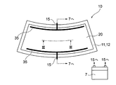
図1〜図24は、本発明による一実施の形態を説明するための図である。このうち図1は、発熱板を備えた自動車を概略的に示す図であり、図2は、発熱板をその板面の法線方向から見た図であり、図3は、図2のIII−III線に沿った発熱板の断面図である。 FIGS. 1-24 is a figure for demonstrating one Embodiment by this invention. Of these, FIG. 1 is a diagram schematically showing an automobile provided with a heat generating plate, FIG. 2 is a view of the heat generating plate viewed from the normal direction of the plate surface, and FIG. It is sectional drawing of the heat generating board along the -III line.
図1に示されているように、乗り物の一例としての自動車1は、フロントウィンドウ、リアウィンドウ、サイドウィンドウ等の窓ガラスを有している。ここでは、フロントウィンドウ5が発熱板10で構成されているものを例示する。また、自動車1はバッテリー等の電源7を有している。
As shown in FIG. 1, an automobile 1 as an example of a vehicle has window glasses such as a front window, a rear window, and a side window. Here, an example in which the front window 5 is composed of a
この発熱板10をその板面の法線方向から見たものを図2に示す。また、図2の発熱板10のIII−III線に対応する断面図を図3に示す。図3に示された例では、発熱板10は、一対の基板11,12と、一対の基板11,12の間に配置された導電体付きシート20と、基板11,12と導電体付きシート20とを接合する接合層13,14と、を有している。なお、図1および図2に示した例では、発熱板10は湾曲しているが、その他の図では、図示の簡略化および理解の容易化のために、発熱板10および基板11,12を平板状に図示している。
FIG. 2 shows the
導電体付きシート20は、基材フィルム21と、基材フィルム21の一方の基板11に対面する面上に設けられた発熱用導電体30と、を有する。発熱用導電体30は、導電性細線41を有するパターン導電体40と、パターン導電体40に通電するための一対のバスバー35と、を有する。
The sheet with
また、図1及び図2によく示されているように、発熱板10は、発熱用導電体30に通電するための配線部15を有している。図示された例では、バッテリー等の電源7によって、配線部15から導電体付きシート20の発熱用導電体30に通電し、発熱用導電体30を抵抗加熱により発熱させる。発熱用導電体30で発生した熱は基板11,12に伝わり、基板11,12が温められる。これにより、基板11,12に付着した結露による曇りを取り除くことができる。また、基板11,12に雪や氷が付着している場合には、この雪や氷を溶かすことができる。したがって、乗員の視界が良好に確保される。尚、図示は省略するが、通常は、配線部15は電源7と発熱用導電体30のバスバー35との間に開閉器が挿入(直列に接続)される。そして、発熱板10の加熱が必要な時のみ開閉器を閉じて発熱用導電体30に通電する。
As well shown in FIGS. 1 and 2, the
以下、発熱板10の各構成要素について説明する。
Hereinafter, each component of the
まず、基板11,12について説明する。基板11,12は、図1で示された例のように自動車のフロントウィンドウに用いる場合、乗員の視界を妨げないよう可視光透過率が高いものを用いることが好ましい。このような基板11,12の材質としては、ソーダライムガラスや青板ガラスが例示できる。基板11,12の可視光透過率は90%以上であることが好ましい。ここで、基板11,12の可視光透過率は、分光光度計((株)島津製作所製「UV−3100PC」、JIS K 0115準拠品)を用いて測定波長380nm〜780nmの範囲内で測定したときの、各波長における透過率の平均値として特定される。なお、基板11,12の一部または全体に着色するなどして、この一部分の可視光透過率を低くしてもよい。この場合、太陽光の直射を遮ったり、車外から車内を視認しにくくしたりすることができる。
First, the
また、基板11,12は、1mm以上5mm以下の厚みを有していることが好ましい。このような厚みであると、強度及び光学特性に優れた基板11,12を得ることができる。一対の基板11,12は、同一の材料で同一に構成されていてもよいし、或いは、材料および構成の少なくとも一方において互いに異なるようにしてもよい。
Moreover, it is preferable that the board |
次に、接合層13,14について説明する。一方の接合層13が、一方の基板11と導電体付きシート20との間に配置され、一方の基板11と導電体付きシート20とを互いに接合する。他方の接合層14が、他方の基板12と導電体付きシート20との間に配置され、他方の基板12と導電体付きシート20とを互いに接合する。
Next, the bonding layers 13 and 14 will be described. One joining
このような接合層13,14としては、種々の接着性または粘着性を有した材料からなる層を用いることができる。また、接合層13,14は、可視光透過率が高いものを用いることが好ましい。典型的な接合層としては、ポリビニルブチラール(PVB)からなる層を例示することができる。接合層13,14の厚みは、それぞれ0.15mm以上1mm以下であることが好ましい。一対の接合層13,14は、同一の材料で同一に構成されていてもよいし、或いは、材料および構成の少なくとも一方において互いに異なるように
してもよい。
As the bonding layers 13 and 14, layers made of materials having various adhesiveness or tackiness can be used. The bonding layers 13 and 14 preferably have a high visible light transmittance. As a typical joining layer, the layer which consists of polyvinyl butyral (PVB) can be illustrated. The thickness of the bonding layers 13 and 14 is preferably 0.15 mm or more and 1 mm or less, respectively. The pair of bonding layers 13 and 14 may be configured identically with the same material, or may be different from each other in at least one of the material and the configuration.
なお、発熱板10には、図示された例に限られず、特定の機能を発揮することを期待されたその他の機能層が設けられても良い。また、1つの機能層が2つ以上の機能を発揮するようにしてもよいし、例えば、発熱板10の基板11,12、接合層13,14、後述する導電体付きシート20の基材フィルム21の、少なくとも一つに何らかの機能を付与するようにしてもよい。発熱板10に付与され得る機能としては、一例として、反射防止(AR)機能、耐擦傷性を有したハードコート(HC)機能、赤外線遮蔽(反射)機能、紫外線遮蔽(反射)機能、防汚機能等を例示することができる。
The
次に、導電体付きシート20について説明する。導電体付きシート20は、基材フィルム21と、基材フィルム21の一方の基板11に対面する面上に設けられた発熱用導電体30と、を有する。導電体付きシート20は、基板11,12と略同一の平面寸法を有して、発熱板10の全体にわたって配置されている。以下、導電体付きシート20の各構成要素について説明する。
Next, the sheet with
基材フィルム21は、発熱用導電体30を支持する基材として機能する。基材フィルム21は、可視光線波長帯域の波長(380nm〜780nm)を透過する一般に言うところの透明である電気絶縁性のフィルムである。基材フィルム21としては、可視光を透過し、発熱用導電体30を適切に支持し得るものであればいかなる材料でもよいが、例えば、ポリエチレンテレフタレート、ポリエチレンナフタレート、ポリカーボネート、ポリスチレン、環状ポリオレフィン等を挙げることができる。また、基材フィルム21は、光透過性や、発熱用導電体30の適切な支持性等を考慮すると、0.03mm以上0.20mm以下の厚みを有していることが好ましい。
The
なお、「透明」とは、当該基材フィルムを介して当該基材フィルムの一方の側から他方の側を透視し得る程度の透明性を有していることを意味しており、例えば、30%以上、より好ましくは70%以上の可視光透過率を有していることを意味する。可視光透過率は、分光光度計((株)島津製作所製「UV−3100PC」、JIS K 0115準拠品)を用いて測定波長380nm〜780nmの範囲内で測定したときの、各波長における透過率の平均値として特定される。 The term “transparent” means that the substrate film is transparent enough to allow the other side of the substrate film to be seen through the substrate film. For example, 30 % Or more, preferably 70% or more. Visible light transmittance is the transmittance at each wavelength when measured within a measurement wavelength range of 380 nm to 780 nm using a spectrophotometer (“UV-3100PC” manufactured by Shimadzu Corporation, JIS K 0115 compliant product). Specified as the average value of.
次に、図4、図6、図8、図10、図12、図14、図17、図19、図21および図23を参照しながら、発熱用導電体30について説明する。図4、図6、図8、図10、図12、図14、図17、図19、図21および図23は、いずれも導電体付きシート20をそのシート面の法線方向から見た平面図であるが、発熱用導電体30のパターン導電体40が互いに異なるパターン構造50を有している。
Next, the
発熱用導電体30は、一対のバスバー35と、一対のバスバー35に間に配置されたパターン導電体40と、を有している。バスバー35は、対応する配線部15と電気的に接続されている。一対のバスバー35間には、配線部15と接続された電源7の電圧が印加されるようになる。パターン導電体40は、所定のパターン構造50で配置された導電性細線41によって形成されている。言い換えると、パターン導電体40は、導電性細線41を用いて形成されたパターン構造50を有する。パターン導電体40は、一対のバスバー35間を連結するようにそれぞれ電気的に接続されている。パターン導電体40は、配線部15及びバスバー35を介して電圧を印加されると、抵抗加熱によって発熱する。そして、この熱が接合層13,14を介して基板11,12に伝わることで、基板11,12が温められる。
The
パターン導電体40のパターン構造50は、第1パターン構造51と、第2パターン構造52と、を少なくとも含む。第1パターン構造51及び第2パターン構造52は、同一の形状を有する少なくとも1種類の単位パターン構造60により形成される。単位パターン構造60は、2以上の区域からなる。ここで、区域とは、例えば図5に符号A1で示すように、単位パターン構造60を構成する線のことをいい、1つの区域は、単位パターン構造60の2つの頂点、分岐点または端点を結ぶ。
The pattern structure 50 of the pattern conductor 40 includes at least a
パターン導電体40の一例が、図4、図6、図8、図10、図12、図17、図19、図21および図23に示されている。図4、図6、図8、図10、図12、図17、図19、図21および図23では、パターン導電体40のパターン構造50は、一対のバスバー35間を連結する複数の第1パターン構造51と第2パターン構造52とを有する。複数の第1パターン構造51及び第2パターン構造52は、一方のバスバー35から他方のバスバー35へ延在しており、第1パターン構造51及び第2パターン構造52の延在方向(第1方向D1)と非平行な方向に、互いから離間して配列されている。とりわけ、図示された例では、第2パターン構造52は、隣り合う2つの第1パターン構造51の間に位置している。
An example of the pattern conductor 40 is shown in FIGS. 4, 6, 8, 10, 12, 17, 19, 21, and 23. 4, 6, 8, 10, 12, 17, 19, 21, and 23, the pattern structure 50 of the pattern conductor 40 includes a plurality of first links that connect the pair of bus bars 35. A
また、他の例として、図14に示された例のように、パターン導電体40のパターン構造50は、一対のバスバー35間に、それぞれがメッシュパターンをなす第1パターン構造51及び第2パターン構造52とを有する。この場合において、第1パターン構造51及び第2パターン構造52は、それぞれ平面充填可能な単位パターン構造60で形成されている。ここで、平面充填可能なパターンとは、任意の大きさの平面を当該パターンのみで隙間なく敷き詰めることができるパターンをいう。第1パターン構造51及び第2パターン構造52は、それぞれ一対のバスバー35間の少なくとも一部の面を充填するよう形成され、一対のバスバー35間の面に形成された第1パターン構造51と第2パターン構造52とは、少なくとも部分的に重なるように形成されている。ここで、第1パターン構造51及び第2パターン構造52が形成される面は、平面に限られず、曲面であってもよい。本実施の形態においては、発熱板10は湾曲しているため、第1パターン構造51及び第2パターン構造52が形成される面は、基板11,12間に組み込まれた際、実際には発熱板10の湾曲に沿った曲面となっている。すなわち、発熱板10内でのパターン導電体40における平面充填可能なパターンは、曲面に沿って形成されている。図14に示す例では、第1パターン構造51及び第2パターン構造52は、それぞれ一対のバスバー35間の面全体に形成されている。したがって、第1パターン構造51と第2パターン構造52とは、それらの全域が一対のバスバー35間の面に重なって、言い換えると一対のバスバー35間の同一の範囲に形成されている。
As another example, as in the example shown in FIG. 14, the pattern structure 50 of the pattern conductor 40 includes a
なお、図示の例では、一対のバスバー35間の面に形成された第1パターン構造51と第2パターン構造52とが、同一面上に形成され、且つ互いに一部を共有することによって重なっている。しかしながら、この態様に代えて、一対のバスバー35間の面に形成された第1パターン構造51と第2パターン構造52とが、異なる面上に形成され、且つ少なくとも部分的に重なるように形成されていてもよい。具体的には、例えば、基材フィルム21の一方の主面に第1パターン構造51が形成され、他方の主面に第2パターン構造52が形成され、且つシート状のパターン導電体40の法線(曲面状である場合には、いずれかの法線)に沿って見た場合に、第1パターン構造51と第2パターン構造52とが互いに重なるように位置している態様が採用されてもよい。つまり、上述の「一対のバスバー35間の面に形成された第1パターン構造51と第2パターン構造52とが、少なくとも部分的に重なるように形成されている」という記載は、一対のバスバー35間の面に形成された第1パターン構造51と第2パターン構造52とが、同一面上に形成され、且つ互いに一部を共有することによって重なっていること、および、一対のバスバー35間の面に形成された第1パターン構造51と第2パターン構造52とが、異なる面上に形成され、且つシート状のパターン導電体40の法線(曲面状である場合には、いずれかの法線)に沿って見た場合に、互いに重なるように位置していること、のいずれかの態様であることを意味している。
In the illustrated example, the
これらのパターン構造50の具体的な例については、図を用いて後に説明する。 Specific examples of these pattern structures 50 will be described later with reference to the drawings.
このようなパターン導電体40及びバスバー35を構成するための材料としては、例えば、金、銀、銅、白金、アルミニウム、クロム、モリブデン、ニッケル、チタン、パラジウム、インジウム、タングステン、及び、これらの合金の一以上を例示することができる。パターン導電体40及びバスバー35は、同一の材料を用いて形成されていてもよいし、或いは、互いに異なる材料を用いて形成されていてもよい。
Examples of the material for forming the pattern conductor 40 and the
パターン導電体40は、上述したように不透明な金属材料を用いて形成され得る。その一方で、パターン導電体40によって覆われていない基材フィルム21上の領域の割合、すなわち非被覆率(図14に示されたパターンでは、「開口率」とも呼ぶ)は、70%以上99%以下程度と高くなっている。また、導電性細線41の線幅は、2μm以上20μm以下程度となっている。このため、パターン導電体40が設けられている領域は、全体として透明に把握され、パターン導電体40の存在が発熱板10の透視性を害さないようになっている。
The pattern conductor 40 may be formed using an opaque metal material as described above. On the other hand, the ratio of the area on the
図3に示された例では、導電性細線41は、全体として矩形状の断面を有している。上述したように、導電性細線41の幅W、すなわち、発熱板10の板面に沿った幅Wは2μm以上20μm以下とし、高さ(厚さ)H、すなわち、発熱板10の板面への法線方向に沿った高さ(厚さ)Hは1μm以上30μm以下とすることが好ましい。このような寸法の導電性細線41によれば、その導電性細線41が十分に細線化されているので、パターン導電体40を効果的に不可視化することができる。
In the example shown in FIG. 3, the conductive
また、図3に示されたように、導電性細線41は、導電性金属層46、導電性金属層46の表面のうち、基材フィルム21に対向する側の面を覆う第1の暗色層47、導電性金属層46の表面のうち、基板11に対向する側の面及び両側面を覆う第2の暗色層48を含むようにしてもよい。優れた導電性を有する金属材料からなる導電性金属層46は、比較的高い反射率を呈する。そして、パターン導電体40の導電性細線41をなす導電性金属層46によって光が反射されると、その反射した光が視認されるようになり、乗員の視界を妨げる場合がある。また、外部から導電性金属層46が視認されると、意匠性が低下する場合がある。そこで、第1及び第2の暗色層47,48が、導電性金属層46の表面の少なくとも一部分を覆っている。第1及び第2の暗色層47,48は、導電性金属層46よりも可視光の反射率が低い層であればよく、例えば黒色等の暗色の層である。この暗色層47,48によって、導電性金属層46が視認されづらくなり、乗員の視界を良好に確保することができる。また、外部から見たときの意匠性の低下を防ぐことができる。
Moreover, as shown in FIG. 3, the conductive
なお、前述したように、発熱板10の透視性または発熱板10を介した視認性を確保する観点から、非被覆率(開口率)が高くなるように、発熱用導電体30の導電性細線41は基材フィルム21上に形成されている。このため、図3に示すように、接合層13と導電体付きシート20の基材フィルム21とは、導電性細線41の非被覆部、すなわち隣り合う導電性細線41の間となる領域を介して接触している。すなわち、発熱用導電体30は、接合層13内に埋め込まれた状態となっている。
As described above, from the viewpoint of ensuring the transparency of the
ところで、上述したように、導電性細線を含んだ発熱板を介して光、例えば対向車の照明を観察した場合、尾を引くように観察される光の筋、すなわち光芒が当該照明の周囲に観察される。このような光芒の発生は、発熱板を介した視認性を悪化させることになる。そして、本件発明者らは、鋭意検討を重ねた結果として、光芒の発生する方向が、発熱板への入射光が導電性細線で回折される方向と一致することを知見した。本件発明者らの知見に基づけば、パターン導電体40をなす導電性細線41の長手方向を不規則化することにより、特定の方向へ光芒が延びることを防止し、光芒を目立たなくさせることができる。しかしながら、導電性細線41の配列を完全に不規則化することは、設計負荷を増加させ好ましくない。また、導電性細線41の配列を不規則化すると、導電性細線での光の反射方向が不規則になり、導電性細線41での反射光が明るく輝く不規則な模様となって目立ってしまう。そこで本件発明者らは、さらに鋭意検討を重ね、導電性細線41の配列の規則性を大きく崩すことなく、極めて効果的に光芒を目立たなくさせることを可能にした。以下、光芒の発生原因と、光芒を目立たなくさせる方法について説明する。
By the way, as described above, when light, for example, illumination of an oncoming vehicle is observed through a heat generating plate including a conductive thin wire, a streak of light observed so as to pull a tail, that is, a light beam, is present around the illumination. Observed. The occurrence of such light glaze deteriorates the visibility through the heat generating plate. As a result of intensive studies, the present inventors have found that the direction in which light is generated coincides with the direction in which incident light on the heating plate is diffracted by the conductive thin wire. Based on the knowledge of the present inventors, by making the longitudinal direction of the conductive
光芒は、発熱板10を透過する光が導電性細線41によって回折することで発生する。すなわち、観察される光芒は、導電性細線41によって起こる回折の回折像が筋状に延びることで発生する。発熱板10に導電性細線41を配置する以上、回折像を発生させないことはできない。したがって、発生する回折像について、視認性に対して影響が小さくすることを考える。
The light beam is generated by light diffracted by the conductive
発熱板10を介した視認性に対して影響が小さい回折像とは、光芒として認識される筋状の光を含まない像である。このような回折像の一例として、回折像が多方向、好ましくは全方向に延び出して個々の回折像が識別できなくなっているものが考えられる。
A diffraction image having a small influence on the visibility through the
ある構造を透過する光の回折像の形状は、その構造について光が透過する部分と遮蔽される部分との境界の形状によって決定される。例えば、長手方向を有する構造、例えば長手方向を有した矩形形状の構造に起因して生じる回折像は、当該構造の長手方向に直交する方向に延びて光芒となる。したがって、一つの構造をなす境界の形状に直交する方向、すなわち1つの構造をなす区域の法線方向が、少なくともその一部において異なっていれば、当該部分によって異なる方向に筋状の光が発生することになり、他の部分によって発生する筋状の光がぼやけることになる。 The shape of the diffraction image of light transmitted through a certain structure is determined by the shape of the boundary between the portion through which light is transmitted and the portion to be shielded. For example, a diffraction image generated due to a structure having a longitudinal direction, for example, a rectangular structure having a longitudinal direction, extends in a direction perpendicular to the longitudinal direction of the structure to form a light beam. Therefore, if the direction perpendicular to the shape of the boundary forming one structure, that is, the normal direction of the area forming one structure is different at least in part, streaky light is generated in different directions depending on the portion. As a result, the streak of light generated by other parts is blurred.
そのような構造として、本発明では、パターン構造50が有する第1パターン構造51及び第2パターン構造52について、第1パターン構造51は単位パターン構造60が第1方向D1に連なって形成されるか、又は、単位パターン構造60が第2方向D2に連なる連接パターンを第1方向D1に複数並べて形成されるように、第2パターン構造52は単位パターン構造60を第3方向D3に連なる連接パターンを第1方向D1に複数並べて形成されるようにすることを提案する。このようなパターン構造50によれば、単位パターン構造60が第1パターン構造51及び第2パターン構造52によってそれぞれ別の方向に連なるため、2つのパターン構造51,52によって異なる方向に筋状の光が発生することになり、パターン構造50全体によって発生する筋状の光をぼやけさせることができる。
As such a structure, in the present invention, with respect to the
さらに、パターン構造50において、単位パターン構造60をなす区域を曲線、特には円弧とすることで、単位パターン構造60の各位置での法線方向を多方向とすることができる。とりわけ、単位パターン構造60をなす各区域を平行移動すること、及び/または各区域を180°回転させた後に平行移動することにより、一つの単位パターン構造を形成する全ての区域を用いて、1以上の自然数個の半円が形成されることが好ましい。区域の法線方向は互いに反対の2方向あるため、区域の集合が半円をなせば、区域の法線方向は全方向に等しく亘り、全方向に等しく筋状の光が発生するからである。 Furthermore, in the pattern structure 50, the normal line direction at each position of the unit pattern structure 60 can be multidirectional by making the area forming the unit pattern structure 60 a curve, particularly an arc. In particular, using all the areas forming one unit pattern structure by translating each area forming the unit pattern structure 60 and / or translating after rotating each area by 180 °, 1 It is preferable to form the above-mentioned natural semicircles. Since the normal direction of the area is two opposite directions, if the set of areas forms a semicircle, the normal direction of the area extends equally in all directions, and streaky light is generated equally in all directions. .
このようなパターン構造50の具体的な例について、図4乃至図24を参照しながら以下で説明する。ただし、本発明は、以下の例に限定されない。 A specific example of such a pattern structure 50 will be described below with reference to FIGS. However, the present invention is not limited to the following examples.
(パターン構造の第1の例)
まず、パターン構造の第1の例として、図4に示されるパターン構造50について説明する。図4に示すパターン構造50は、図5に示す単位パターン構造60aで形成されている。
(First example of pattern structure)
First, a pattern structure 50 shown in FIG. 4 will be described as a first example of the pattern structure. The pattern structure 50 shown in FIG. 4 is formed of the unit pattern structure 60a shown in FIG.
図5の単位パターン構造60aは、正六角形の外接円を正六角形の各頂点で分割して6つの円弧とし、1つおきに位置する円弧を180°回転させて形成されている。この6つの円弧が、第1の例における単位パターン構造60aをなす区域である。すなわち、第1の例における単位パターン構造60aは、6つの区域A1〜A6からなる。図5に示すように、区域A1〜A6は、この順で接続されている。この例における単位パターン構造60aと他の単位パターン構造60aとは、区域A1と区域A4、区域A2と区域A5、区域A3と区域A6を、それぞれ共有可能である。また、このように形成された単位パターン構造60aでは、当然に、単位パターン構造60aをなす区域A1〜A6を平行移動すること、及び/または各区域を180°回転させた後に平行移動することにより、一つの単位パターン構造を形成する全ての区域を用いて、1以上の自然数個の半円、具体的には2つの半円が形成される。 The unit pattern structure 60a in FIG. 5 is formed by dividing a regular hexagonal circumscribed circle at each apex of the regular hexagon into six arcs, and rotating every other arc by 180 °. These six arcs are areas forming the unit pattern structure 60a in the first example. That is, the unit pattern structure 60a in the first example includes six sections A1 to A6. As shown in FIG. 5, the sections A1 to A6 are connected in this order. The unit pattern structure 60a and other unit pattern structures 60a in this example can share the area A1 and the area A4, the area A2 and the area A5, and the area A3 and the area A6, respectively. Further, in the unit pattern structure 60a formed in this manner, naturally, the areas A1 to A6 forming the unit pattern structure 60a are translated and / or the respective areas are rotated by 180 ° and then translated. Using all the areas forming one unit pattern structure, one or more natural semicircles, specifically, two semicircles are formed.
図4に示すパターン構造50は、第1パターン構造51、第2パターン構造52、及び第3パターン構造53を有する。第1パターン構造51は、図5に示す単位パターン構造60aが第1方向D1に連なって形成されている。この場合において、例えば、互いに隣接する単位パターン構造60aは区域A2と区域A5を共有している。第2パターン構造52は、図5に示す単位パターン構造60aが第1方向D1とは異なる第3方向D3に連なる連接パターン52aを第1方向に複数並べて形成されている。この場合において、例えば、連接パターン52aの形成には、単位パターン構造60aが第1パターン構造51と同様に区域を共有し、連接パターン52aを第1方向に並べるに際しては、互いに隣接する連接パターン52aに含まれる単位パターン構造60aの区域A1と区域A4を共有する。図4の例において、連接パターン52aは、2つの単位パターン構造60aを有する。また、第3方向D3は、第1方向D1に対し30°傾いている。第3パターン構造53は、図5に示す単位パターン構造60aが第1方向D1及び第3方向D3とは異なる第2方向D2に連なる連接パターン53aを第1方向D1に複数並べて形成されている。この場合において、例えば、連接パターン53aの形成及び連接パターン53aを第1方向D1に並べるに際しては、単位パターン構造60aが第2パターン構造52と同様に区域を共有する。図4の例において、連接パターン53aは、4つの単位パターン構造60を有する。また、第2方向D2は、第1方向D1に対し15°傾いている。この場合において、第1パターン構造51、第2パターン構造52及び第3パターン構造53は、それぞれ平面充填可能なパターンとなっている。
A pattern structure 50 shown in FIG. 4 includes a
(パターン構造の第2の例)
次に、パターン構造の第2の例として、図6に示されるパターン構造50について説明する。図6に示すパターン構造50は、図7に示す単位パターン構造60a、60bで形成されている。
(Second example of pattern structure)
Next, a pattern structure 50 shown in FIG. 6 will be described as a second example of the pattern structure. The pattern structure 50 shown in FIG. 6 is formed of unit pattern structures 60a and 60b shown in FIG.
図7の単位パターン構造60a、60bは、それぞれ正方形の外接円を正方形の各頂点で分割して4つの円弧とし、1つおきに位置する円弧を180°回転させて形成されている。単位パターン構造60aと単位パターン構造60bとでは、180°回転させる円弧の位置が異なる。この8つの円弧が、第2の例における単位パターン構造60aの区域A1〜A4及び単位パターン構造60bの区域B1〜B4である。図7に示すように、区域A1〜A4及び区域B1〜B4は、この順で接続されている。また、単位パターン構造60aにおいて180°回転させた円弧は、区域A2、A4であり、単位パターン構造60bにおいて180°回転させた円弧は、区域B1、B3である。この例における単位パターン構造60aと単位パターン構造60bとは、区域A1と区域B3、区域A2と区域B4、区域A3と区域B1、区域A4と区域B2を、それぞれ共有可能である。また、このように形成された各単位パターン構造60a,60bでは、当然に、単位パターン構造60a,60bをなす区域A1〜A4又は区域B1〜B4を平行移動すること、及び/または各区域を180°回転させた後に平行移動することにより、一つの単位パターン構造を形成する全ての区域を用いて、1以上の自然数個の半円、具体的には4つの半円が形成される。 The unit pattern structures 60a and 60b in FIG. 7 are formed by dividing a circumscribed circle of a square at each vertex of the square into four arcs, and rotating every other arc by 180 °. The unit pattern structure 60a and the unit pattern structure 60b differ in the position of the arc to be rotated by 180 °. These eight arcs are areas A1 to A4 of the unit pattern structure 60a and areas B1 to B4 of the unit pattern structure 60b in the second example. As shown in FIG. 7, the sections A1 to A4 and the sections B1 to B4 are connected in this order. The arcs rotated by 180 ° in the unit pattern structure 60a are areas A2 and A4, and the arcs rotated by 180 ° in the unit pattern structure 60b are areas B1 and B3. The unit pattern structure 60a and the unit pattern structure 60b in this example can share the area A1 and the area B3, the area A2 and the area B4, the area A3 and the area B1, and the area A4 and the area B2. Further, in each of the unit pattern structures 60a and 60b formed in this way, naturally, the areas A1 to A4 or the areas B1 to B4 forming the unit pattern structures 60a and 60b are translated, and / or each area is 180. By rotating in parallel after being rotated, one or more natural semicircles, specifically, four semicircles are formed using all the areas forming one unit pattern structure.
図6に示すパターン構造50は、第1パターン構造51及び第2パターン構造52を有する。第1パターン構造51は、図7に示す単位パターン構造60a及び単位パターン構造60bが第1方向D1に連なって形成されている。この場合において、例えば、互いに隣接する単位パターン構造60a、60bは、区域A2と区域B4、及び区域A4と区域B2をそれぞれ共有している。第2パターン構造52は、図7に示す単位パターン構造60a及び単位パターン構造60bが第1方向D1とは異なる第3方向D3に連なる連接パターン52aを第1方向D1に複数並べて形成されている。この場合において、例えば、連接パターン52aの形成には、単位パターン構造60a、60bが第1パターン構造51と同様に区域を共有し、連接パターン52aを第1方向D1に並べるに際しては、互いに隣接する連接パターン52aに含まれる単位パターン構造60a、60bの区域A1と区域B3を共有する。図6の例において、連接パターン52aは、単位パターン構造60a、60bを2つずつ有する。また、第3方向D3は、第1方向D1に対し20°傾いている。この場合において、第1パターン構造51及び第2パターン構造52は、それぞれ平面充填可能なパターンとなっている。
A pattern structure 50 shown in FIG. 6 includes a
(パターン構造の第3の例)
次に、パターン構造の第3の例として、図8に示されるパターン構造50について説明する。図8に示すパターン構造50は、図9に示す単位パターン構造60a、60b、60cで形成されている。
(Third example of pattern structure)
Next, a pattern structure 50 shown in FIG. 8 will be described as a third example of the pattern structure. The pattern structure 50 shown in FIG. 8 is formed of unit pattern structures 60a, 60b, and 60c shown in FIG.
図9の単位パターン構造60aは、正方形の外接円を正方形の各頂点で分割して4つの円弧とし、1つおきに位置する円弧を180°回転させて形成されている。単位パターン構造60bは、単位パターン構造60aの180°回転させた2つの円弧と同一の円弧で形成されている。単位パターン構造60cは、正方形の外接円を正方形の各頂点で分割して4つの円弧とし、3つの円弧を180°回転させて形成されている。この10個の円弧が、第3の例における単位パターン構造60aの区域A1〜A4、単位パターン構造60bの区域B1,B2、及び単位パターン構造60cの区域C1〜C4である。図9に示すように、区域A1〜A4及び区域C1〜C4は、この順で接続されている。また、単位パターン構造60aにおいて180°回転させた円弧は、区域A2、A4であり、単位パターン構造60cにおいて180°回転させた円弧は、区域C1,C2,C3である。この例における単位パターン構造60a、60b、60cは、区域A1と区域C3、区域A2と区域C4、区域A3と区域C1、区域A4と区域B1、区域B1と区域C2を、それぞれ共有可能である。 The unit pattern structure 60a in FIG. 9 is formed by dividing a square circumscribed circle at each vertex of the square into four arcs, and rotating every other arc by 180 °. The unit pattern structure 60b is formed by the same arc as two arcs rotated by 180 ° of the unit pattern structure 60a. The unit pattern structure 60c is formed by dividing a circumscribed circle of a square at each vertex of the square to form four arcs, and rotating the three arcs by 180 °. These ten arcs are areas A1 to A4 of the unit pattern structure 60a, areas B1 and B2 of the unit pattern structure 60b, and areas C1 to C4 of the unit pattern structure 60c in the third example. As shown in FIG. 9, the sections A1 to A4 and the sections C1 to C4 are connected in this order. Further, the arcs rotated by 180 ° in the unit pattern structure 60a are areas A2 and A4, and the arcs rotated by 180 ° in the unit pattern structure 60c are areas C1, C2, and C3. The unit pattern structures 60a, 60b, and 60c in this example can share the areas A1 and C3, the areas A2 and C4, the areas A3 and C1, the areas A4 and B1, and the areas B1 and C2, respectively.
図8に示すパターン構造50は、第1パターン構造51及び第2パターン構造52を有する。第1パターン構造51は、図9に示す単位パターン構造60a、単位パターン構造60b及び単位パターン構造60cが第1方向D1に連なって形成されている。この場合において、例えば、互いに隣接する単位パターン構造60a、60b、60cは、区域A4と区域B1、区域B2と区域C2、及び区域C4と区域A2をそれぞれ共有している。第2パターン構造52は、図9に示す単位パターン構造60a及び単位パターン構造60bが第1方向D1とは異なる第3方向D3に連なる連接パターン52aを第1方向D1に複数並べて形成されている。この場合において、例えば、連接パターン52aの形成には、単位パターン構造60a、60b、60cが第1パターン構造51と同様に区域を共有し、連接パターン52aを第1方向D1に並べるに際しては、互いに隣接する連接パターン52aに含まれる単位パターン構造60a、60cの区域A1と区域C3を共有する。図8の例において、連接パターン52aは、単位パターン構造60a、60b、60cをそれぞれ2つずつ有する。また、第3方向D3は、第1方向に対し20°傾いている。この場合において、第1パターン構造51及び第2パターン構造52は、それぞれ平面充填可能なパターンとなっている。
A pattern structure 50 shown in FIG. 8 includes a
(パターン構造の第4の例)
次に、パターン構造の第4の例として、図10に示されるパターン構造50について説明する。図10に示すパターン構造50は、図11に示す単位パターン構造60a、60bで形成されている。
(Fourth example of pattern structure)
Next, a pattern structure 50 shown in FIG. 10 will be described as a fourth example of the pattern structure. The pattern structure 50 shown in FIG. 10 is formed of unit pattern structures 60a and 60b shown in FIG.
図11の単位パターン構造60a、60bは、それぞれ正八角形の外接円を正八角形の各頂点で分割して8つの円弧とし、1つおきに位置する円弧を180°回転させて形成されている。単位パターン構造60aと単位パターン構造60bとでは、180°回転させる円弧の位置が異なる。この8つの円弧が、第2の例における単位パターン構造60aをなす区域A1〜A8及び単位パターン構造60bをなす区域B1〜B8である。図11に示すように、区域A1〜A8及び区域B1〜B8は、この順で接続されている。また、単位パターン構造60aにおいて180°回転させた円弧は、区域A1、A3、A5、A7であり、単位パターン構造60bにおいて180°回転させた円弧は、区域B2、B4、B6、B8である。この例における単位パターン構造60a、60bは、区域A1と区域B5、区域A2と区域B6、区域A3と区域B7、区域A4と区域B8、区域A5と区域B1、区域A6と区域B2、区域A7と区域B3、区域A8と区域B4を、それぞれ共有可能である。また、このように形成された各単位パターン構造60a,60bでは、当然に、単位パターン構造60a,60bをなす区域A1〜A8又は区域B1〜B8を平行移動すること、及び/または各区域を180°回転させた後に平行移動することにより、一つの単位パターン構造を形成する全ての区域を用いて、1以上の自然数個の半円、具体的には4つの半円が形成される。 The unit pattern structures 60a and 60b in FIG. 11 are each formed by dividing a regular octagonal circumscribed circle at each apex of the regular octagon into eight arcs, and rotating every other arc by 180 °. The unit pattern structure 60a and the unit pattern structure 60b differ in the position of the arc to be rotated by 180 °. These eight arcs are the areas A1 to A8 forming the unit pattern structure 60a and the areas B1 to B8 forming the unit pattern structure 60b in the second example. As shown in FIG. 11, the sections A1 to A8 and the sections B1 to B8 are connected in this order. Further, the arcs rotated by 180 ° in the unit pattern structure 60a are areas A1, A3, A5, and A7, and the arcs rotated by 180 ° in the unit pattern structure 60b are areas B2, B4, B6, and B8. The unit pattern structures 60a and 60b in this example are the areas A1 and B5, the areas A2 and B6, the areas A3 and B7, the areas A4 and B8, the areas A5 and B1, the areas A6 and B2, and the areas A7. Area B3, area A8, and area B4 can be shared. Further, in each of the unit pattern structures 60a and 60b formed in this way, naturally, the areas A1 to A8 or the areas B1 to B8 forming the unit pattern structures 60a and 60b are translated, and / or each area is 180. By rotating in parallel after being rotated, one or more natural semicircles, specifically, four semicircles are formed using all the areas forming one unit pattern structure.
図10に示すパターン構造50は、第1パターン構造51及び第2パターン構造52を有する。第1パターン構造51は、図11に示す単位パターン構造60a及び単位パターン構造60bが第1方向D1に連なって形成されている。この場合において、例えば、互いに隣接する単位パターン構造60a、60bは、区域A3と区域B7、及び区域A7と区域B3をそれぞれ共有している。第2パターン構造52は、図11に示す単位パターン構造60a及び単位パターン構造60bが第1方向D1とは異なる第3方向D3に連なる連接パターン52aを第1方向D1に複数並べて形成されている。この場合において、例えば、連接パターン52aの形成には、単位パターン構造60a、60bが第1パターン構造51と同様に区域を共有し、連接パターン52aを第1方向D1に並べるに際しては、互いに隣接する連接パターン52aに含まれる単位パターン構造60a、60bの区域A1と区域B5を共有する。図10の例において、連接パターン52aは、単位パターン構造60a、60bを3つずつ有する。また、第3方向D3は、第1方向D1に対し12.5°傾いている。
A pattern structure 50 shown in FIG. 10 includes a
(パターン構造の第5の例)
次に、パターン構造の第5の例として、図12に示されるパターン構造50について説明する。図12に示すパターン構造50は、図13に示す単位パターン構造60a、60b、60c、60eで形成されている。なお、単位パターン構造60a、60bは、パターン構造の第4の例と同じであるため、説明を省略する。
(Fifth example of pattern structure)
Next, the pattern structure 50 shown in FIG. 12 will be described as a fifth example of the pattern structure. The pattern structure 50 shown in FIG. 12 is formed of unit pattern structures 60a, 60b, 60c, and 60e shown in FIG. Since the unit pattern structures 60a and 60b are the same as the fourth example of the pattern structure, the description thereof is omitted.
図13の単位パターン構造60c、60eは、それぞれ単位パターン構造60bをなす円弧のうち180°回転させた円弧と同一の円弧からなる。この8つの円弧が、第5の例における単位パターン構造60cをなす区域C1〜C4及び単位パターン構造60eをなす区域E1〜E4である。図13に示すように、区域C1〜C4及び区域E1〜E4が、この順で接続されている。この例における単位パターン構造60a、60b、60c、60eは、区域A1と区域B5、区域A2と区域E3、区域A3と区域B7、区域A4と区域C4、区域A5と区域B1、区域A6と区域E1、区域A7と区域B3、区域A8と区域C2、区域B2と区域C3、区域B4と区域E4、区域B6と区域C1、区域B8と区域E2を、それぞれ共有可能である。 The unit pattern structures 60c and 60e in FIG. 13 are formed of the same arc as the arc rotated by 180 ° out of the arcs forming the unit pattern structure 60b. These eight arcs are the areas C1 to C4 forming the unit pattern structure 60c and the areas E1 to E4 forming the unit pattern structure 60e in the fifth example. As shown in FIG. 13, the sections C1 to C4 and the sections E1 to E4 are connected in this order. The unit pattern structures 60a, 60b, 60c, and 60e in this example are the areas A1 and B5, the areas A2 and E3, the areas A3 and B7, the areas A4 and C4, the areas A5 and B1, the areas A6 and E1. Area A7 and Area B3, Area A8 and Area C2, Area B2 and Area C3, Area B4 and Area E4, Area B6 and Area C1, Area B8 and Area E2 can be shared.
図12に示すパターン構造50は、第1パターン構造51及び第2パターン構造52を有する。第1パターン構造51は、図13に示す単位パターン構造60a及び単位パターン構造60bが第1方向D1に連なって形成されている。この場合において、例えば、互いに隣接する単位パターン構造60a、60b、60c、60eは、区域A3と区域B7、区域A7と区域B3、区域A8と区域C2、区域A6と区域E1、区域B1との区域C3、及び区域B4と区域E4を、それぞれ共有している。第2パターン構造52は、図11に示す単位パターン構造60a、60b、60c、60eが第1方向D1とは異なる第3方向D3に連なる連接パターン52aを第1方向D1に複数並べて形成されている。この場合において、例えば、連接パターン52aの形成には、単位パターン構造60a、60b、60c、60eが第1パターン構造51と同様に区域を共有し、連接パターン52aを第1方向D1に並べるに際しては、互いに隣接する連接パターン52aに含まれる単位パターン構造60a、60b、60c、60eの区域A1と区域B5、区域A2と区域E3、及び区域B6と区域C1をそれぞれ共有する。図12の例において、連接パターン52aは、単位パターン構造60a、60b、60c、60eを3つずつ有する。また、第3方向D3は、第1方向D1に対し12.5°傾いている。この場合において、第1パターン構造51及び第2パターン構造52は、それぞれ平面充填可能なパターンとなっている。
A pattern structure 50 shown in FIG. 12 includes a
(パターン構造の第6の例)
次に、パターン構造の第6の例として、図14に示されるパターン構造50について説明する。図14に示すパターン構造50は、第1の例と同じ図5に示す単位パターン構造60aで形成されている。
(Sixth example of pattern structure)
Next, a pattern structure 50 shown in FIG. 14 will be described as a sixth example of the pattern structure. The pattern structure 50 shown in FIG. 14 is formed of the unit pattern structure 60a shown in FIG. 5 which is the same as the first example.
図14に示すパターン構造50は、図15に示す第1パターン構造51及び図16に示す第2パターン構造52を有する。第1パターン構造51は、図5に示す単位パターン構造60aが第1方向D1に連なって形成されている。さらに、第1パターン構造51は、第1方向D1に非平行な方向にも連なって形成されている。すなわち、第1パターン構造51は、単位パターン構造60aを2次元配列して形成される。この場合において、互いに隣接する単位パターン構造60aは、区域A1と区域A4、区域A2と区域A5及び区域A3と区域A6を、それぞれ共有している。第2パターン構造52は、図5に示す単位パターン構造60aが第1方向D1とは異なる第3方向D3に連なる連接パターン52aを第1方向D1に複数並べて形成されている。さらに、第2パターン構造52は、第1パターン構造51と同様に、第1方向D1とは非平行な方向にも連なって形成されている。この場合においても、互いに隣接する単位パターン構造60aは、区域A1と区域A4、区域A2と区域A5及び区域A3と区域A6を、それぞれ共有している。また、第3方向D3は、第1方向に対し30°傾いている。
A pattern structure 50 shown in FIG. 14 includes a
上述したように、図14に示すパターン構造50の第6の例では、第1パターン構造51及び第2パターン構造52は、それぞれ平面充填可能なパターンであり、それぞれ一対のバスバー35間の面全体を充填するよう形成されている。したがって、第1パターン構造51と第2パターン構造52とは、それらの全域が一対のバスバー35間の面に重なって形成されている。
As described above, in the sixth example of the pattern structure 50 shown in FIG. 14, each of the
(パターン構造の第7の例)
次に、パターン構造の第7の例として、図17に示されるパターン構造50について説明する。図17に示すパターン構造50は、図18に示す単位パターン構造60aで形成されている。
(Seventh example of pattern structure)
Next, the pattern structure 50 shown in FIG. 17 will be described as a seventh example of the pattern structure. The pattern structure 50 shown in FIG. 17 is formed of a unit pattern structure 60a shown in FIG.
図18の単位パターン構造60aは、中心角45°の基準の円弧(A1)と、基準の円弧(A1)の一方の端部の接線方向に関して当該基準の円弧(A1)と線対称となる円弧(A2)と、基準の円弧(A1)の一方の端部に関して当該基準の円弧(A1)と点対称となる円弧(A3)と、基準の円弧(A1)の一方の端部の接線方向に直交する方向に関して当該基準の円弧(A1)と線対称となる円弧(A4)と、をこの順で接続することによって形成されている。この4つの円弧が、第7の例における単位パターン構造60aの区域A1〜A4である。図18に示すように、区域A1〜A4は、この順で接続されている。 The unit pattern structure 60a in FIG. 18 includes a reference arc (A1) having a central angle of 45 ° and an arc that is line-symmetric with the reference arc (A1) with respect to the tangential direction of one end of the reference arc (A1). (A2), an arc (A3) that is point-symmetric with the reference arc (A1) with respect to one end of the reference arc (A1), and a tangential direction of one end of the reference arc (A1) The reference arc (A1) and the arc (A4) that is line-symmetric with respect to the orthogonal direction are connected in this order. These four arcs are areas A1 to A4 of the unit pattern structure 60a in the seventh example. As shown in FIG. 18, the sections A1 to A4 are connected in this order.
図17に示すパターン構造50は、第1パターン構造51及び第2パターン構造52を有する。第1パターン構造51は、図18に示す単位パターン構造60aが第1方向D1に連なって形成されている。この場合において、例えば、互いに隣接する単位パターン構造60aは、区域A1と区域A2の間の頂点と区域A3と区域A4の間の頂点とを共有している。第2パターン構造52は、図18に示す単位パターン構造60aが第1方向D1とは異なる第3方向D3に連なる連接パターン52aを第1方向D1に複数並べて形成されている。この場合において、例えば、連接パターン52aの形成には、単位パターン構造60aが第1パターン構造51と同様に区域の間の頂点を共有し、連接パターン52aを第1方向D1に並べるに際しては、互いに隣接する連接パターン52aに含まれる単位パターン構造60aの区域A1と区域A4の間の頂点と区域A2と区域A3との間の頂点とを共有する。図17の例において、連接パターン52aは、単位パターン構造60aを3つずつ有する。また、第3方向D3は、第1方向D1に対し12.5°傾いている。
A pattern structure 50 shown in FIG. 17 includes a
(パターン構造の第8の例)
次に、パターン構造の第8の例として、図19に示されるパターン構造50について説明する。図19に示すパターン構造50は、図20に示す単位パターン構造60a1〜60a6、及び区域B1〜B6で形成されている。なお、単位パターン構造60a1〜60a6は、それぞれパターン構造の第4の例の単位パターン構造60a(図11参照)と同じであるため、説明を省略する。
(Eighth example of pattern structure)
Next, a pattern structure 50 shown in FIG. 19 will be described as an eighth example of the pattern structure. The pattern structure 50 shown in FIG. 19 is formed of unit pattern structures 60a1 to 60a6 and areas B1 to B6 shown in FIG. The unit pattern structures 60a1 to 60a6 are the same as the unit pattern structure 60a (see FIG. 11) of the fourth example of the pattern structure, and thus the description thereof is omitted.
図20の区域B1〜B6は、中心角90°で切り取られた同一の半径を有する円弧である。図示された例においては、区域B1〜B6の円弧の弦の長さは、単位パターン構造60a1〜60a6の区域A1〜A8の円弧の弦の長さと同一である。区域B1と区域B6、区域B2と区域B3、区域B4と区域B5は、それぞれ平行移動によって互いに重なり合う。図20に示すように、単位パターン構造60a1と単位パターン構造60a2、単位パターン構造60a3と単位パターン構造60a4、単位パターン構造60a5と単位パターン構造60a6が、それぞれ隣り合っている。これらの各対が隣り合う方向と交差する方向で、単位パターン構造60a1、60a3、60a5及び単位パターン構造60a2、60a4、60a6が、それぞれこの順で並んでいる。単位パターン構造60a1の区域A5とA6との間の頂点と単位パターン構造60a2の区域A8とA1との間の頂点を、区域B1が接続している。単位パターン構造60a1の区域A6とA7との間の頂点と単位パターン構造60a3の区域A3とA4との間の頂点を、区域B2が接続している。単位パターン構造60a2の区域A6とA7との間の頂点と単位パターン構造60a4の区域A3とA4との間の頂点を、区域B3が接続している。単位パターン構造60a3の区域A7とA8との間の頂点と単位パターン構造60a5の区域A2とA3との間の頂点を、区域B4が接続している。単位パターン構造60a4の区域A7とA8との間の頂点と単位パターン構造60a6の区域A2とA3との間の頂点を、区域B5が接続している。単位パターン構造60a5の区域A5とA6との間の頂点と単位パターン構造60a6の区域A8とA1との間の頂点を、区域B6が接続している。 Areas B1 to B6 in FIG. 20 are circular arcs having the same radius cut at a central angle of 90 °. In the illustrated example, the length of the arc chord in the areas B1 to B6 is the same as the length of the arc chord in the areas A1 to A8 of the unit pattern structures 60a1 to 60a6. Area B1 and area B6, area B2 and area B3, and area B4 and area B5 overlap each other by translation. As shown in FIG. 20, the unit pattern structure 60a1 and the unit pattern structure 60a2, the unit pattern structure 60a3 and the unit pattern structure 60a4, and the unit pattern structure 60a5 and the unit pattern structure 60a6 are adjacent to each other. The unit pattern structures 60a1, 60a3, 60a5 and the unit pattern structures 60a2, 60a4, 60a6 are arranged in this order in the direction in which these pairs intersect each other. Area B1 connects the apex between areas A5 and A6 of unit pattern structure 60a1 and the apex between areas A8 and A1 of unit pattern structure 60a2. Area B2 connects the apex between areas A6 and A7 of unit pattern structure 60a1 and the apex between areas A3 and A4 of unit pattern structure 60a3. Area B3 connects the apex between areas A6 and A7 of unit pattern structure 60a2 and the apex between areas A3 and A4 of unit pattern structure 60a4. The area B4 connects the apex between the areas A7 and A8 of the unit pattern structure 60a3 and the apex between the areas A2 and A3 of the unit pattern structure 60a5. Area B5 connects the vertex between areas A7 and A8 of unit pattern structure 60a4 and the vertex between areas A2 and A3 of unit pattern structure 60a6. Area B6 connects the apex between areas A5 and A6 of unit pattern structure 60a5 and the apex between areas A8 and A1 of unit pattern structure 60a6.
図19に示すパターン構造50は、第1パターン構造51及び第2パターン構造52を有する。第1パターン構造51は、図20に示す単位パターン構造60a1〜60a6及び区域B1〜B6が組み合わさった構造が第1方向D1に連なって形成されている。この場合において、例えば、単位パターン構造60a1〜60a6及び区域B1〜B6が組み合わさった構造は、単位パターン構造60a1の全ての区域と単位パターン構造60a5の全ての区域、単位パターン構造60a2の全ての区域と単位パターン構造60a6の全ての区域、区域B1と区域B6を、それぞれ共有して連なっている。言い換えると、第1パターン構造51では、単位パターン構造60a1〜60a6及び区域B1〜B6が組み合わさった構造が、その一部の区域でなるパターン部分(単位パターン構造60a1の全ての区域、単位パターン構造60a2の全ての区域、及び区域B1でなる部分)を、他の単位パターン構造60a1〜60a6及び区域B1〜B6が組み合わさった構造の一部の区域でなるパターン部分(単位パターン構造60a5の全ての区域、単位パターン構造60a6の全ての区域、及び区域B6でなる部分)に重ねることで、単位パターン構造60a1〜60a6及び区域B1〜B6が組み合わさった複数の構造が連なって第1パターン構造51が形成されている。すなわち、本例では、パターン部分を互いに重ねることが、結果的に、区域の共有状態を形成している。第2パターン構造52は、図20に示す単位パターン構造60a1〜60a6及び区域B1〜B6が組み合わさった構造が第1方向D1とは異なる第3方向D3に連なる連接パターン52aを第1方向D1に複数並べて形成されている。この場合において、例えば、連接パターン52aの形成には、単位パターン構造60a1〜60a6及び区域B1〜B6が組み合わさった構造が第1パターン構造51と同様に区域を共有している。また、連接パターン52aを第1方向D1に並べるに際しては、単位パターン構造60a2の全ての区域と単位パターン構造60a5の全ての区域を共有する。言い換えると、第2パターン構造52では、連接パターン52aが、その一部の区域でなるパターン部分(単位パターン構造60a2でなる部分)を、他の連接パターン52aの一部の区域でなるパターン部分(単位パターン構造60a5でなる部分)に重ねることで、複数の連接パターン52aが連なって第2パターン構造52が形成されている。すなわち、パターン部分を互いに重ねることが、結果的に、区域の共有状態を形成している。図19の例において、連接パターン52aは、単位パターン構造60a1〜60a6及び区域B1〜B6が組み合わさった構造を2つずつ有する。また、第3方向D3は、第1方向D1に対し12.5°傾いている。
A pattern structure 50 shown in FIG. 19 includes a
(パターン構造の第9の例)
次に、パターン構造の第9の例として、図21に示されるパターン構造50について説明する。図21に示すパターン構造50は、図22に示す単位パターン構造60a1〜60a15、及び区域B1〜B18で形成されている。なお、単位パターン構造60a1〜60a15は、それぞれパターン構造の第4の例の単位パターン構造60a(図11参照)と同じであるため、説明を省略する。また、図示の都合上、図22においては単位パターン構造60a1〜60a15の区域A1〜A7については符号の図示を省略する。各符号と図示された区域は、図11の単位パターン構造60aと同一である。
(Ninth example of pattern structure)
Next, a pattern structure 50 shown in FIG. 21 will be described as a ninth example of the pattern structure. The pattern structure 50 shown in FIG. 21 is formed of unit pattern structures 60a1 to 60a15 and areas B1 to B18 shown in FIG. The unit pattern structures 60a1 to 60a15 are the same as the unit pattern structure 60a (see FIG. 11) of the fourth example of the pattern structure, and thus the description thereof is omitted. For convenience of illustration, in FIG. 22, reference numerals are omitted for the areas A1 to A7 of the unit pattern structures 60a1 to 60a15. Each symbol and the illustrated area are the same as the unit pattern structure 60a of FIG.
図22の区域B1〜B18は、中心角90°で切り取られた同一の半径を有する円弧である。図示された例においては、区域B1〜B18の円弧の弦の長さは、単位パターン構造60a1〜60a15の区域A1〜A8の弦の長さと同一である。図示された例において、区域B1と区域B4、B9、B13、区域B2と区域B3、B7、B8、B14、区域B5と区域B11、B12、B16、B17、区域B6と区域B10、B15、B18は、それぞれ平行移動によって互いに重なり合う。また、図22に示すように、単位パターン構造60a1と単位パターン構造60a2、単位パターン構造60a3と単位パターン構造60a4、単位パターン構造60a5と単位パターン構造60a6、単位パターン構造60a7と単位パターン構造60a8、単位パターン構造60a8と単位パターン構造60a9、単位パターン構造60a10と単位パターン構造60a11、単位パターン構造60a12と単位パターン構造60a13、単位パターン構造60a14と単位パターン構造60a15が、それぞれ隣り合っている。これらの各対が隣り合う方向と交差する方向で、単位パターン構造60a1、60a3、60a7、60a10、単位パターン構造60a2、60a4、60a5、60a8、60a11、60a12、60a14及び単位パターン構造60a6、60a9、60a13、60a15が、それぞれこの順で並んでいる。単位パターン構造60a1、60a2の間、単位パターン構造60a3、60a4の間、単位パターン構造60a7、60a8の間、及び単位パターン構造60a10、60a11の間の、区域A4とA5との間の頂点と区域A1とA2との間の頂点を区域B1、B4、B9、B13がそれぞれ接続している。単位パターン構造60a1、60a3の間、単位パターン構造60a2、60a4の間、単位パターン構造60a5、60a8の間、単位パターン構造60a6、60a9の間、及び単位パターン構造60a11、60a12の間の、区域A7とA8との間の頂点と区域A2とA3との間の頂点を区域B2、B3、B7、B8、B14がそれぞれ接続している。単位パターン構造60a4、60a5の間、単位パターン構造60a7、60a10の間、単位パターン構造60a8、60a11の間、単位パターン構造60a12、60a14、及び単位パターン構造60a13、60a15の間の、区域A6とA7との間の頂点と区域A3とA4との間の頂点を区域B5、B11、B12、B16、B17がそれぞれ接続している。単位パターン構造60a5、60a6の間、単位パターン構造60a8、60a9の間、単位パターン構造60a12、60a13の間、及び単位パターン構造60a14、60a15の間の、区域A5とA6との間の頂点と区域A8とA1との間の頂点を区域B6、B10、B15、B18がそれぞれ接続している。 Areas B1 to B18 in FIG. 22 are circular arcs having the same radius cut at a central angle of 90 °. In the illustrated example, the chord lengths of the arcs in the areas B1 to B18 are the same as the chord lengths in the areas A1 to A8 of the unit pattern structures 60a1 to 60a15. In the illustrated example, area B1 and area B4, B9, B13, area B2 and area B3, B7, B8, B14, area B5 and area B11, B12, B16, B17, area B6 and area B10, B15, B18 are , And overlap each other by translation. As shown in FIG. 22, the unit pattern structure 60a1 and the unit pattern structure 60a2, the unit pattern structure 60a3 and the unit pattern structure 60a4, the unit pattern structure 60a5 and the unit pattern structure 60a6, the unit pattern structure 60a7 and the unit pattern structure 60a8, and the unit The pattern structure 60a8 and the unit pattern structure 60a9, the unit pattern structure 60a10 and the unit pattern structure 60a11, the unit pattern structure 60a12 and the unit pattern structure 60a13, and the unit pattern structure 60a14 and the unit pattern structure 60a15 are adjacent to each other. The unit pattern structures 60a1, 60a3, 60a7, 60a10, the unit pattern structures 60a2, 60a4, 60a5, 60a8, 60a11, 60a12, 60a14 and the unit pattern structures 60a6, 60a9, 60a13 in a direction crossing the adjacent direction. , 60a15 are arranged in this order. Between the unit pattern structures 60a1 and 60a2, between the unit pattern structures 60a3 and 60a4, between the unit pattern structures 60a7 and 60a8, and between the unit pattern structures 60a10 and 60a11, the vertex between the areas A4 and A5 and the area A1 Sections B1, B4, B9, and B13 connect the vertices between A2 and A2, respectively. Between the unit pattern structures 60a1, 60a3, between the unit pattern structures 60a2, 60a4, between the unit pattern structures 60a5, 60a8, between the unit pattern structures 60a6, 60a9, and between the unit pattern structures 60a11, 60a12 and Areas B2, B3, B7, B8, and B14 connect the apex between A8 and the apex between areas A2 and A3, respectively. Areas A6 and A7 between the unit pattern structures 60a4 and 60a5, between the unit pattern structures 60a7 and 60a10, between the unit pattern structures 60a8 and 60a11, between the unit pattern structures 60a12 and 60a14, and between the unit pattern structures 60a13 and 60a15 Sections B5, B11, B12, B16, and B17 connect the vertices between and the vertices between sections A3 and A4, respectively. Between the unit pattern structures 60a5 and 60a6, between the unit pattern structures 60a8 and 60a9, between the unit pattern structures 60a12 and 60a13, and between the unit pattern structures 60a14 and 60a15, the vertex between the areas A5 and A6 and the area A8 Sections B6, B10, B15, and B18 connect the vertices between A1 and A1, respectively.
図21に示すパターン構造50は、第1パターン構造51及び第2パターン構造52を有する。第1パターン構造51は、図22に示す単位パターン構造60a1〜60a15及び区域B1〜B18が組み合わさった構造が第1方向D1に連なって形成されている。この場合において、例えば、単位パターン構造60a1〜60a15及び区域B1〜B18が組み合わさった構造は、単位パターン構造60a2の全ての区域と単位パターン構造60a14の全ての区域を、共有して連なっている。言い換えると、第1パターン構造51では、単位パターン構造60a1〜60a15及び区域B1〜B18が組み合わさった構造が、その一部の区域でなるパターン部分(単位パターン構造60a2の全ての区域でなる部分)を、他の単位パターン構造60a1〜60a15及び区域B1〜B18が組み合わさった構造の一部の区域でなるパターン部分(単位パターン構造60a14の全ての区域でなる部分)に重ねることで、単位パターン構造60a1〜60a15及び区域B1〜B18が組み合わさった複数の構造が連なって第1パターン構造51が形成されている。すなわち、本例でも、パターン部分を互いに重ねることが、結果的に、区域の共有状態を形成している第2パターン構造52は、図22に示す単位パターン構造60a1〜60a15及び区域B1〜B18が組み合わさった構造が第1方向D1とは異なる第3方向D3に連なる連接パターン52aを第1方向D1に複数並べて形成されている。この場合において、例えば、連接パターン52aの形成には、単位パターン構造60a1〜60a15及び区域B1〜B18が組み合わさった構造が第1パターン構造51と同様に区域を共有する。また、連接パターン52aを第1方向D1に並べるに際しては、単位パターン構造60a1の全ての区域と単位パターン構造60a15の全ての区域を共有する。言い換えると、第2パターン構造52では、連接パターン52aが、その一部の区域でなるパターン部分(単位パターン構造60a1でなる部分)を、他の連接パターン52aの一部の区域でなるパターン部分(単位パターン構造60a15でなる部分)に重ねることで、複数の連接パターン52aが連なって第2パターン構造52が形成されている。すなわち、パターン部分を互いに重ねることが、結果的に、区域の共有状態を形成している。図21の例において、連接パターン52aは、単位パターン構造60a1〜60a15及び区域B1〜B18が組み合わさった構造を2つずつ有する。また、第3方向D3は、第1方向D1に対し10°傾いている。
A pattern structure 50 shown in FIG. 21 includes a
(パターン構造の第10の例)
次に、パターン構造の第10の例として、図23に示されるパターン構造50について説明する。図23に示すパターン構造50は、図24に示す単位パターン構造60a、60b、60cで形成されている。なお、単位パターン構造60aは、パターン構造の第4の例の単位パターン構造60a(図11参照)と同じであるため、説明を省略する。
(Tenth example of pattern structure)
Next, a pattern structure 50 shown in FIG. 23 will be described as a tenth example of the pattern structure. The pattern structure 50 shown in FIG. 23 is formed of unit pattern structures 60a, 60b, and 60c shown in FIG. Since the unit pattern structure 60a is the same as the unit pattern structure 60a (see FIG. 11) of the fourth example of the pattern structure, the description thereof is omitted.
図24の単位パターン構造60bは、中心角90°で切り取られた同一の半径を有する2つの円弧と、単位パターン構造60aの180°回転させた円弧である区域A3、A7と同一の円弧と、で形成されている。各円弧の弦の長さは、同一となっている。図示された例において、単位パターン構造60bは、これらの円弧の弦が正方形を形成し、その正方形に外接する形状となるように接続されて形成されている。単位パターン構造60cは、中心角90°で切り取られた同一の半径を有する2つの円弧と、単位パターン構造60aの180°回転させた円弧である区域A1、A5と同一の円弧と、で形成されている。各円弧の弦の長さは、同一となっている。図示された例において、単位パターン構造60cは、これらの円弧の弦が正方形を形成し、その正方形に外接する形状となるように接続されて形成されている。これらの円弧が、第10の例における単位パターン構造60bの区域B1〜B4、及び単位パターン構造60cの区域C1〜C4である。図24に示すように、区域B1〜B4及び区域C1〜C4は、この順で接続されている。この例における単位パターン構造60a、60b、60cは、区域A3と区域B4、区域A7と区域B2、区域A1と区域C3、区域A5と区域C1を、それぞれ共有可能である。 The unit pattern structure 60b of FIG. 24 includes two arcs having the same radius cut at a central angle of 90 °, arcs identical to the areas A3 and A7 that are arcs rotated by 180 ° of the unit pattern structure 60a, It is formed with. The length of the chord of each arc is the same. In the illustrated example, the unit pattern structure 60b is formed by connecting the arc chords so as to form a square and circumscribe the square. The unit pattern structure 60c is formed by two arcs having the same radius cut by a central angle of 90 ° and arcs identical to the areas A1 and A5 which are arcs rotated by 180 ° of the unit pattern structure 60a. ing. The length of the chord of each arc is the same. In the illustrated example, the unit pattern structure 60c is formed by connecting the arc chords so as to form a square and circumscribe the square. These arcs are the areas B1 to B4 of the unit pattern structure 60b and the areas C1 to C4 of the unit pattern structure 60c in the tenth example. As shown in FIG. 24, the sections B1 to B4 and the sections C1 to C4 are connected in this order. The unit pattern structures 60a, 60b, and 60c in this example can share the areas A3 and B4, the areas A7 and B2, the areas A1 and C3, and the areas A5 and C1, respectively.
図23に示すパターン構造50は、第1パターン構造51及び第2パターン構造52を有する。第1パターン構造51は、図24に示す単位パターン構造60a及び単位パターン構造60bが第1方向D1に連なって形成されている。この場合において、例えば、互いに隣接する単位パターン構造60a、60bは、区域A3と区域B4及び区域A7と区域B2をそれぞれ共有している。第2パターン構造52は、図24に示す単位パターン構造60a及び単位パターン構造60bが第1方向D1とは異なる第3方向D3に連なり、連なりの端部の単位パターン構造60aに単位パターン構造60cが連なる連接パターン52aを第1方向D1に複数並べて形成されている。この場合において、例えば、連接パターン52aの形成には、単位パターン構造60a、60bが第1パターン構造51と同様に区域を共有し、連なりの端部において単位パターン構造60a、60cが区域A1と区域C3を共有する。連接パターン52aを第1方向D1に並べるに際しては、互いに隣接する連接パターン52aに含まれる単位パターン構造60a、60cの区域A5と区域C1を共有する。図23の例において、連接パターン52aは、単位パターン構造60a、60bをそれぞれ5つずつ有し、単位パターン構造60cを1つ有する。また、第3方向D3は、第1方向に対し12.5°傾いている。この場合において、第1パターン構造51及び第2パターン構造52は、それぞれ平面充填可能なパターンとなっている。
A pattern structure 50 shown in FIG. 23 includes a
パターン構造の第1〜第10の例において、単位パターン構造60が第1パターン構造51及び第2パターン構造52によってそれぞれ別の方向に連なるため、2つのパターン構造51,52によって異なる方向に筋状の光が発生することになり、また、区域の法線方向は全方向に亘るため、パターン構造50全体によって発生する筋状の光をぼやけさせることができる。したがって、パターン導電体40がこのパターン構造50を有する発熱用導電体30においては、発生する光芒を目立たなくさせることができる。
In the first to tenth example of the pattern structure, the unit pattern structure 60 is connected in different directions by the
パターン構造の第1の例においては、単位パターン構造60が第3パターン構造53をさらに有するので、3つのパターン構造51,52,53によって異なる方向に筋状の光が発生する。具体的には、パターン構造の第1の例においては、第1パターン構造51に含まれる単位パターン構造60がそれぞれ別の向きで配置された3種の区域を有し、それぞれの向きの区域が同じ長さであるため、第1パターン構造51によって発生する光芒が延びる方向は、3方向に均等に延びる。すなわち、1つの光芒が延びる方向を基準の0°の方向と考えると、第1パターン構造51による光芒は、0°−180°方向、60°−240°方向、120°−300°方向の3方向に延びる。また、第1パターン構造51が連なる方向である第1方向D1に対し、第2パターン構造52が連なる方向である第2方向D2は、15°傾いており、第3パターン構造53が連なる方向である第3方向D3は、30°傾いている。したがって、第1パターン構造51によって発生する光芒が延びる方向に対し、第2パターン構造52によって発生する光芒が延びる方向は、15°傾き、第3パターン構造53によって発生する光芒が延びる方向は、30°傾く。よって、第2パターン構造52による光芒は、15°−195°方向、75°−225°方向、135°−215°方向の3方向に延び、第3パターン構造53による光芒は、30°−210°方向、90°−270°方向、150°−330°方向の3方向に延びる。それぞれのパターン構造によって異なる方向に光芒が発生するため、パターン構造50全体によって発生する光芒をより目立たなくさせることができる
In the first example of the pattern structure, since the unit pattern structure 60 further includes the
また、パターン構造の第1、第2、第4、第6及び第9の例において、単位パターン構造60をなす各区域を平行移動すること、及び/または各区域を180°回転させた後に平行移動することにより、一つの単位パターン構造を形成する全ての区域を用いて、1以上の自然数個の半円が形成されるため、区域の法線方向は全方向に等しく亘る。これにより、全方向に等しく筋状の光が発生するため、発生する光芒をより目立たなくさせることができる。 Also, in the first, second, fourth, sixth and ninth examples of the pattern structure, the respective areas forming the unit pattern structure 60 are translated and / or parallel after being rotated by 180 °. By moving, all the areas forming one unit pattern structure are used to form one or more natural semicircles, so that the normal direction of the area extends equally in all directions. Thereby, since streak-like light is generated equally in all directions, the generated light glare can be made inconspicuous.
なお、第1の例において、パターン構造50は、第1パターン構造51を有さず、第2パターン構造52と第3パターン構造53のみを有してもよい。すなわち、単位パターン構造60が第1方向に連なって形成される第1パターン構造51が存在しなくてもよい。このような場合でも、単位パターン構造60が第2パターン構造52及び第3パターン構造53によってそれぞれ別の方向に連なるため、2つのパターン構造52,53によって異なる方向に筋状の光が発生することになる。したがって、パターン導電体40がこのパターン構造50を有する発熱用導電体30においても、発生する光芒を目立たなくさせることができる。なお、この態様においては、本発明でいう「第1パターン構造」は、実施の形態に係る第3パターン構造53に対応する。
In the first example, the pattern structure 50 may not include the
また、第1の例において、パターン構造50は、第3パターン構造53を有さず、第1パターン構造51と第2パターン構造52のみを有してもよい。このような場合でも、上述したように、単位パターン構造60が第1パターン構造51及び第2パターン構造52によってそれぞれ別の方向に連なるため、パターン導電体40がこのパターン構造50を有する発熱用導電体30においては、発生する光芒を目立たなくさせることができる。
In the first example, the pattern structure 50 may not include the
なお、パターン構造の第1〜第10の例においては、第2パターン構造52が1種類の連接パターン52aしか有していなかった。しかしながら、第2パターン構造52が複数の種類の連接パターンを有していてもよい。
In the first to tenth examples of the pattern structure, the
また、パターン構造の第1〜第10の例において、互いに隣接する単位パターン構造60が共有する区域は、区域全体を共有していた。しかしながら、区域の共有は、少なくとも部分的であってもよい。また、パターン構造の第8及び第9の例(図19、21)のよう、互いに隣接する単位パターン構造60が複数の区域を共有してもよい。 In the first to tenth example of the pattern structure, the area shared by the unit pattern structures 60 adjacent to each other shares the entire area. However, sharing of the area may be at least partial. Further, as in the eighth and ninth examples of pattern structures (FIGS. 19 and 21), the unit pattern structures 60 adjacent to each other may share a plurality of areas.
パターン構造の第1〜第3、第5、第6の例では、第1パターン構造51及び第2パターン構造52は、平面充填可能なパターンとなっている。この場合、パターン導電体40が規則的なパターン構造50によって導電性細線41が配置されるため、導電性細線41による外部からの光の反射方向が規則的になる。したがって、パターン導電体40を有する発熱板10を介した視界において、導電性細線41での反射光が明るく輝く不規則な模様となって目立つことを防止することができる。
In the first to third, fifth, and sixth examples of the pattern structure, the
単位パターン構造60は、第1、第2、第4〜第7及び第10の例のように、4以上の区域からなることが好ましく、第1及び第6の例のように、6の区域からなることがより好ましい。この場合、少ない種類の単位パターン構造60のみで連接パターンを形成することができる。したがって、簡易な単位パターン構造60のみでパターン構造50を形成することができる。 The unit pattern structure 60 is preferably composed of four or more areas as in the first, second, fourth to seventh and tenth examples, and has six areas as in the first and sixth examples. More preferably, it consists of. In this case, the connection pattern can be formed with only a few types of unit pattern structures 60. Therefore, the pattern structure 50 can be formed with only the simple unit pattern structure 60.
第1〜第5、第7〜第10の例のように、第1パターン構造51及び第2パターン構造52が第1方向と非平行な方向に配列されていると、発熱板10においてパターン構造50で配置される導電性細線41の密度を小さくすることができる。光芒の発生原因となる導電性細線41の密度が小さいと、発生する光芒の密度もまた小さくなる。すなわち、発生する光芒の明るさを低減することができる。
When the
上述した例において、単位パターン構造60は区域によってある領域を画成しており、1つの単位パターン構造60において区域は連続していた。しかしながら、これに限らず、例えば単位パターン構造60において、区域の任意の位置に切欠が設けられている等して、区域が不連続であってもよい。 In the example described above, the unit pattern structure 60 defines a certain region by the area, and the area is continuous in one unit pattern structure 60. However, the present invention is not limited to this. For example, in the unit pattern structure 60, the area may be discontinuous, for example, a notch is provided at an arbitrary position in the area.
次に、発熱板10の製造方法の一例について、説明する。
Next, an example of a method for manufacturing the
まず、基材フィルム21上に第1の暗色層47を形成するようになる暗色膜を設ける。
First, a dark color film that forms the first
次に、導電性金属層46を形成するようになる金属膜を暗色膜上に設ける。金属膜は、公知の方法で形成され得る。例えば、銅箔等の金属箔を貼着する方法、電界めっき及び無電界めっきを含むめっき法、スパッタリング法、CVD法、PVD法、イオンプレーティング法、又はこれらの二以上を組み合わせた方法を採用することができる。
Next, a metal film for forming the
その後、金属膜上に、レジストパターンを設ける。レジストパターンは、形成されるべきパターン導電体40に対応した形、すなわちパターン構造50の形となっている。このレジストパターンは、公知のフォトリソグラフィー技術を用いたパターニングにより形成することができる。 Thereafter, a resist pattern is provided on the metal film. The resist pattern has a shape corresponding to the pattern conductor 40 to be formed, that is, a pattern structure 50. This resist pattern can be formed by patterning using a known photolithography technique.
次に、レジストパターンをマスクとして、金属膜及び暗色膜をエッチングする。このエッチングにより、金属膜及び暗色膜がレジストパターンと略同一のパターンにパターニングされる。この結果、パターニングされた金属膜から、導電性細線41の一部をなすようになる導電性金属層46が、形成される。また、パターニングされた暗色膜から、導電性細線41の一部をなすようになる第1の暗色層47が、形成される。
Next, the metal film and the dark color film are etched using the resist pattern as a mask. By this etching, the metal film and the dark color film are patterned into a pattern substantially the same as the resist pattern. As a result, a
なお、エッチング方法は特に限られることはなく、公知の方法が採用できる。公知の方法としては、例えば、エッチング液を用いるウェットエッチングや、プラズマエッチングなどが挙げられる。その後、レジストパターンを除去する。 The etching method is not particularly limited, and a known method can be employed. Known methods include, for example, wet etching using an etchant, plasma etching, and the like. Thereafter, the resist pattern is removed.
その後、導電性金属層46の第1の暗色層47が設けられた面と反対側の面及び側面に第2の暗色層48を形成する。第2の暗色層48は、例えば導電性金属層46をなす材料の一部分に暗色化処理(黒化処理)を施して、導電性金属層46をなしていた一部分から、金属酸化物や金属硫化物からなる第2の暗色層48を形成することができる。また、導電性金属層46の表面に第2の暗色層48を設けるようにしてもよい。また、導電性金属層46の表面を粗化して第2の暗色層48を設けるようにしてもよい。
Thereafter, the second
以上の工程によって、基材フィルム21上に発熱用導電体30が形成され、導電体付きシート20が作製される。
Through the above steps, the
最後に、発熱用導電体30の側から接合層13及び基板11を積層して、導電体付きシート20と基板11とを接合する。同様に、基材フィルム21の側から接合層14及び基板12を積層して、導電体付きシート20と基板12とを接合する。これにより、図3に示した発熱板10が作製される。
Finally, the
以上のように、本実施の形態の発熱用導電体30では、第1パターン構造51は、単位パターン構造60が第1方向に連なって形成されるか、又は、単位パターン構造60が第1方向とは異なる第2方向に連なる連接パターンを第1方向に複数並べて形成され、第2パターン構造52は、単位パターン構造60が第1方向及び第2方向とは異なる第3方向に連なる連接パターンを第1方向に複数並べて形成されることで、発熱用導電体によって発生する光芒を目立たなくすることができる。
As described above, in the
なお、上述した実施の形態に対して様々な変更を加えることが可能である。 Note that various modifications can be made to the above-described embodiment.
上述した実施の形態では、発熱板10が、基材フィルム21を有している導電体付きシート20を備える例を示したが、製造過程において基材フィルム21を剥離させる等によって、発熱板10中に基材フィルム21を有さないようにしてもよい。この場合、発熱板10の全体を薄型にすることができ、また軽量化することができる。さらに、発熱用導電体30から生じる熱を、発熱板10全体により早く伝達させることもできる。
In embodiment mentioned above, although the
前述した実施の形態において、発熱板10が曲面状に形成されている例を示したが、この例に限られず、発熱板10が、平板状に形成されていてもよい。
In the above-described embodiment, the example in which the
発熱板10は、自動車1のリアウィンドウ、サイドウィンドウやサンルーフに用いてもよい。また、自動車以外の、鉄道車両、航空機、船舶、宇宙船等の乗り物の窓或いは扉の透明部分に用いてもよい。
The
さらに、発熱板10は、乗り物以外にも、特に室内と室外とを区画する箇所、例えばビルや店舗、住宅の窓或いは扉の透明部分、建物の窓又は扉、冷蔵庫、展示箱、戸棚等の收納乃至保管設備の窓あるいは扉の透明部分等に使用することもできる。
Further, the
なお、以上において上述した実施の形態に対するいくつかの変形例を説明してきたが、当然に、複数の変形例を適宜組み合わせて適用することも可能である。 In addition, although the some modification with respect to embodiment mentioned above was demonstrated above, naturally, it is also possible to apply combining several modifications suitably.
1 自動車
5 フロントウィンドウ
7 電源
10 発熱板
11 基板
12 基板
13 接合層
14 接合層
15 配線部
20 導電体付きシート
21 基材フィルム
30 発熱用導電体
35 バスバー
40 パターン導電体
41 導電性細線
46 導電性金属層
47 第1の暗色層
48 第2の暗色層
50 パターン構造
51 第1パターン構造
52 第2パターン構造
52a 連接パターン
60 単位パターン構造
DESCRIPTION OF SYMBOLS 1 Car 5
Claims (11)
前記一対のバスバーを連結するパターン導電体と、を備え、
前記パターン導電体は、導電性細線を用いて形成されたパターン構造を有し、
前記パターン構造は、2以上の区域からなる少なくとも1種類の単位パターン構造で形成される第1パターン構造と、前記第1パターン構造の単位パターン構造と同一の少なくとも1種類の単位パターン構造で形成される第2パターン構造と、を含み、
前記第1パターン構造は、前記単位パターン構造が第1方向に連なって形成されるか、又は、前記単位パターン構造が第1方向とは異なる第2方向に連なる連接パターンを第1方向に複数並べて形成され、
前記第2パターン構造は、前記単位パターン構造が前記第1方向及び第2方向とは異なる第3方向に連なる連接パターンを前記第1方向に複数並べて形成される、発熱用導電体。 A pair of bus bars to which a voltage is applied;
A pattern conductor connecting the pair of bus bars,
The pattern conductor has a pattern structure formed using conductive thin wires,
The pattern structure is formed of a first pattern structure formed of at least one unit pattern structure composed of two or more areas, and at least one type of unit pattern structure identical to the unit pattern structure of the first pattern structure. A second pattern structure
The first pattern structure is formed by connecting the unit pattern structures in a first direction or arranging a plurality of connection patterns in the first direction in which the unit pattern structures are connected in a second direction different from the first direction. Formed,
The second pattern structure is a heating conductor in which the unit pattern structure is formed by arranging a plurality of connection patterns in the first direction, the connection patterns being connected in a third direction different from the first direction and the second direction.
前記第2パターン構造は、隣り合う2つの前記第1パターン構造の間に位置し、前記第1方向に非平行な方向に配列されている、請求項1または2に記載の発熱用導電体。 The first pattern structure is arranged in a direction non-parallel to the first direction,
3. The heating conductor according to claim 1, wherein the second pattern structure is located between two adjacent first pattern structures and arranged in a direction non-parallel to the first direction. 4.
2以上の前記第2パターン構造は、前記一対のバスバーの間の少なくとも一部の面を充填するよう形成され、
前記一対のバスバーの間の面に形成された前記第1パターン構造と前記第2パターン構造とは、少なくとも部分的に重なるように形成されている、請求項2に記載の発熱用導電体。 The two or more first pattern structures are formed to fill at least a part of the surface between the pair of bus bars,
The two or more second pattern structures are formed to fill at least a part of the surface between the pair of bus bars,
The heat generating conductor according to claim 2, wherein the first pattern structure and the second pattern structure formed on a surface between the pair of bus bars are formed so as to at least partially overlap each other.
前記連接パターンに含まれる前記単位パターン構造は、前記第2方向または前記第3方向に連なる際に他の単位パターン構造と共有可能な区域と、当該連接パターンを前記第1方向に並べる際に他の連接パターンの単位パターン構造と共有可能な区域と、を少なくとも含む、請求項1乃至5のいずれか一項に記載の発熱用導電体。 The unit pattern structures adjacent to each other at least partially share an area;
The unit pattern structure included in the connection pattern includes an area that can be shared with another unit pattern structure when connecting in the second direction or the third direction, and another when arranging the connection pattern in the first direction. The heat generating conductor according to claim 1, comprising at least a unit pattern structure of the connection pattern and a shareable area.
前記一対の基板の間に配置された請求項1乃至9のいずれか一項に記載の発熱用導電体と、を備える、発熱板。 A pair of substrates;
A heat generating plate, comprising: the heat generating conductor according to any one of claims 1 to 9 disposed between the pair of substrates.
Applications Claiming Priority (2)
| Application Number | Priority Date | Filing Date | Title |
|---|---|---|---|
| JP2016231490 | 2016-11-29 | ||
| JP2016231490 | 2016-11-29 |
Publications (2)
| Publication Number | Publication Date |
|---|---|
| JP2018092881A true JP2018092881A (en) | 2018-06-14 |
| JP6913297B2 JP6913297B2 (en) | 2021-08-04 |
Family
ID=62565691
Family Applications (1)
| Application Number | Title | Priority Date | Filing Date |
|---|---|---|---|
| JP2017051754A Expired - Fee Related JP6913297B2 (en) | 2016-11-29 | 2017-03-16 | Heat-generating conductors, heat-generating plates and vehicles |
Country Status (1)
| Country | Link |
|---|---|
| JP (1) | JP6913297B2 (en) |
Cited By (1)
| Publication number | Priority date | Publication date | Assignee | Title |
|---|---|---|---|---|
| WO2020122141A1 (en) * | 2018-12-13 | 2020-06-18 | 大日本印刷株式会社 | Pattern conductor, pattern conductor with bus bar, plyboard, partition member, and moving body |
Citations (5)
| Publication number | Priority date | Publication date | Assignee | Title |
|---|---|---|---|---|
| US20090169877A1 (en) * | 2005-10-06 | 2009-07-02 | Pilkington Group Limitd | Laminated Glazing |
| JP2011514647A (en) * | 2008-03-17 | 2011-05-06 | エルジー・ケム・リミテッド | Heating element and method for manufacturing the same |
| JP2012519329A (en) * | 2009-02-26 | 2012-08-23 | スリーエム イノベイティブ プロパティズ カンパニー | TOUCH SCREEN SENSOR AND PATTERN SUBSTRATE HAVING OVER-MINIMUM PATTERN WITH LOW VIEW |
| JP2016099872A (en) * | 2014-11-25 | 2016-05-30 | 大日本印刷株式会社 | Electrode substrate for touch panel, touch panel, and display device |
| JP2016190617A (en) * | 2015-03-31 | 2016-11-10 | 大日本印刷株式会社 | Transparent heating plate and vehicle |
-
2017
- 2017-03-16 JP JP2017051754A patent/JP6913297B2/en not_active Expired - Fee Related
Patent Citations (5)
| Publication number | Priority date | Publication date | Assignee | Title |
|---|---|---|---|---|
| US20090169877A1 (en) * | 2005-10-06 | 2009-07-02 | Pilkington Group Limitd | Laminated Glazing |
| JP2011514647A (en) * | 2008-03-17 | 2011-05-06 | エルジー・ケム・リミテッド | Heating element and method for manufacturing the same |
| JP2012519329A (en) * | 2009-02-26 | 2012-08-23 | スリーエム イノベイティブ プロパティズ カンパニー | TOUCH SCREEN SENSOR AND PATTERN SUBSTRATE HAVING OVER-MINIMUM PATTERN WITH LOW VIEW |
| JP2016099872A (en) * | 2014-11-25 | 2016-05-30 | 大日本印刷株式会社 | Electrode substrate for touch panel, touch panel, and display device |
| JP2016190617A (en) * | 2015-03-31 | 2016-11-10 | 大日本印刷株式会社 | Transparent heating plate and vehicle |
Cited By (3)
| Publication number | Priority date | Publication date | Assignee | Title |
|---|---|---|---|---|
| WO2020122141A1 (en) * | 2018-12-13 | 2020-06-18 | 大日本印刷株式会社 | Pattern conductor, pattern conductor with bus bar, plyboard, partition member, and moving body |
| JPWO2020122141A1 (en) * | 2018-12-13 | 2021-10-28 | 大日本印刷株式会社 | Pattern conductor, pattern conductor with bus bar, mating plate, partition member and moving body |
| JP7405096B2 (en) | 2018-12-13 | 2023-12-26 | 大日本印刷株式会社 | Patterned conductors, patterned conductors with busbars, laminated plates, partition members, and moving objects |
Also Published As
| Publication number | Publication date |
|---|---|
| JP6913297B2 (en) | 2021-08-04 |
Similar Documents
| Publication | Publication Date | Title |
|---|---|---|
| CN108293275A (en) | Heating electrode device, energized heating glass, heating plate, vehicle, building window, sheet with conductor, conductive pattern sheet, conductive heating element, laminated glass, and method for manufacturing conductive heating element | |
| JP2016143914A (en) | Heating plate and vehicle | |
| WO2018012553A1 (en) | Patterned conductor, sheet with conductor, heat-generating plate, vehicle, and method for producing patterned conductor | |
| JP6951674B2 (en) | Heat-generating conductors, sheets with conductors, heat-generating plates and vehicles | |
| JP6814398B2 (en) | Vehicles with heating plates, conductive pattern sheets and heating plates | |
| JP2016141210A (en) | Heating plate, conductive pattern sheet, and vehicle equipped with the heating plate | |
| JP6913294B2 (en) | Heating plates, seats with conductors, windows for vehicles and buildings | |
| JP6745073B2 (en) | Conductive pattern sheet, heating plate, vehicle equipped with heating plate, and method for manufacturing heating plate | |
| JP2016102055A (en) | Glass laminate, pattern sheet and manufacturing method of glass laminate | |
| JP2016102056A (en) | Glass laminate and manufacturing method thereof | |
| JP6770702B2 (en) | Conductive heating elements, laminated glass and vehicles | |
| JP2018092881A (en) | Heat-generating conductor, heat-generating plate and vehicle | |
| JP6976676B2 (en) | Transparent heating plate and vehicle | |
| JP7316535B2 (en) | Heat-generating conductor, heat-generating plate, and method for producing heat-generating conductor | |
| JP7405096B2 (en) | Patterned conductors, patterned conductors with busbars, laminated plates, partition members, and moving objects | |
| JP6579432B2 (en) | Transparent heating plate, vehicle, heater and building window | |
| JP6897706B2 (en) | Heat plate and vehicle | |
| JP6597574B2 (en) | Transparent heating plate, vehicle and building windows | |
| JP2018055942A (en) | Heat-generating conductor, sheet with conductor, heating plate, vehicle and building | |
| JP6941291B2 (en) | Heat-generating conductors, sheets with conductors, heat-generating plates and vehicles | |
| JP7356640B2 (en) | Heat generating conductor, heat generating plate, moving object | |
| KR20210132036A (en) | Pattern conductor, heating plate and moving body | |
| JP6740715B2 (en) | Pattern conductors, conductors for heat generation, sheets with conductors, heat generating plates, vehicles and buildings | |
| JP6828239B2 (en) | Vehicles with heating plates, conductive pattern sheets and heating plates | |
| JP6579433B2 (en) | Transparent heating plate and vehicle with transparent heating plate |
Legal Events
| Date | Code | Title | Description |
|---|---|---|---|
| A621 | Written request for application examination |
Free format text: JAPANESE INTERMEDIATE CODE: A621 Effective date: 20200129 |
|
| A977 | Report on retrieval |
Free format text: JAPANESE INTERMEDIATE CODE: A971007 Effective date: 20201228 |
|
| A131 | Notification of reasons for refusal |
Free format text: JAPANESE INTERMEDIATE CODE: A131 Effective date: 20210122 |
|
| TRDD | Decision of grant or rejection written | ||
| A01 | Written decision to grant a patent or to grant a registration (utility model) |
Free format text: JAPANESE INTERMEDIATE CODE: A01 Effective date: 20210611 |
|
| A61 | First payment of annual fees (during grant procedure) |
Free format text: JAPANESE INTERMEDIATE CODE: A61 Effective date: 20210624 |
|
| R150 | Certificate of patent or registration of utility model |
Ref document number: 6913297 Country of ref document: JP Free format text: JAPANESE INTERMEDIATE CODE: R150 |
|
| LAPS | Cancellation because of no payment of annual fees |