JP2018056829A - COMMUNICATION DEVICE, ITS CONTROL METHOD, AND PROGRAM - Google Patents
COMMUNICATION DEVICE, ITS CONTROL METHOD, AND PROGRAM Download PDFInfo
- Publication number
- JP2018056829A JP2018056829A JP2016191329A JP2016191329A JP2018056829A JP 2018056829 A JP2018056829 A JP 2018056829A JP 2016191329 A JP2016191329 A JP 2016191329A JP 2016191329 A JP2016191329 A JP 2016191329A JP 2018056829 A JP2018056829 A JP 2018056829A
- Authority
- JP
- Japan
- Prior art keywords
- network
- communication
- unit
- scanning
- wireless communication
- Prior art date
- Legal status (The legal status is an assumption and is not a legal conclusion. Google has not performed a legal analysis and makes no representation as to the accuracy of the status listed.)
- Granted
Links
Images


Landscapes
- Mobile Radio Communication Systems (AREA)
Abstract
【課題】 無線通信において、通信相手との接続を確立するまで時間がかかる場合があった。【解決手段】 通信装置において、無線通信手段と、中継装置が形成したネットワークをスキャンするスキャン手段と、前記中継装置が形成したネットワークに参加する参加手段と、前記通信装置が中継装置となりネットワークを形成する形成手段と、前記スキャン手段と前記形成手段とを並行して動作させるよう制御する制御手段とを有し、前記スキャン手段と前記形成手段とが並行して動作している状態で、所定のネットワークが前記スキャン手段により発見された場合、前記制御手段は、前記形成手段で形成したネットワークを破棄すると共に、前記参加手段により、前記所定のネットワークに参加するよう制御することを特徴とした通信装置。【選択図】 図2PROBLEM TO BE SOLVED: To establish a connection with a communication partner in wireless communication in some cases. SOLUTION: In a communication device, a wireless communication means, a scanning means for scanning a network formed by a relay device, a participating means for participating in a network formed by the relay device, and the communication device serving as a relay device to form a network. A predetermined forming means is provided, and a control means for controlling the scanning means and the forming means to operate in parallel is provided, and the scanning means and the forming means are operating in parallel. When a network is found by the scanning means, the control means discards the network formed by the forming means and controls the participating means to join the predetermined network. .. [Selection diagram] Fig. 2
Description
本発明は、通信装置、その制御方法、およびプログラムに関する。 The present invention relates to a communication device, a control method thereof, and a program.
従来、無線通信を介して、二つ以上の機器間での通信が行われている。この無線通信において、一般的にネットワークの生成がどちらであるかによって、それぞれの装置の動作が異なる。例えば、無線LANのアクセスポイントの機能を搭載した機器においては、自らネットワークを生成し、他の装置からの接続要求を受け付ける。一方、無線LANのアクセスポイントの機能を搭載した機器に接続する他の装置は、アクセスポイント機能を搭載した機器が発信するビーコンを受信することで、周囲のアクセスポイント機能を搭載した機器をスキャンする。 Conventionally, communication between two or more devices is performed via wireless communication. In this wireless communication, the operation of each device generally differs depending on which of the networks is generated. For example, a device equipped with a wireless LAN access point function creates a network by itself and accepts connection requests from other devices. On the other hand, other devices connected to a device equipped with a wireless LAN access point function scan a device equipped with a nearby access point function by receiving a beacon transmitted by the device equipped with the access point function. .
近年、携帯機器に、上記のアクセスポイントの機能を搭載することで、他にアクセスポイントの機能を搭載している機器が存在していない状態でもインフラ接続を実現することが行われている。例えば特許文献1には、まず周囲のアクセスポイントをスキャンし、アクセスポイントが見つからなかった場合に、直接通信モードで無線接続を行う技術が開示されている。 In recent years, by mounting the above-described access point function on a mobile device, it is possible to realize infrastructure connection even when no other device having the access point function exists. For example, Patent Document 1 discloses a technique of first scanning a surrounding access point and performing wireless connection in a direct communication mode when an access point is not found.
しかしながら、アクセスポイントのスキャンには、ある程度の時間を要する。そのため、アクセスポイントが存在しない場合に直接接続に移行するまで時間がかかるという問題があった。この点に鑑み、本発明は、無線通信において、通信相手との接続を確立するまでの時間を短くすることを目的とする。 However, scanning an access point requires a certain amount of time. Therefore, there is a problem that it takes time to shift to direct connection when there is no access point. In view of this point, an object of the present invention is to shorten the time required for establishing a connection with a communication partner in wireless communication.
上記目的を達成するために、本発明は、無線通信により外部機器と通信を行う通信装置において、無線通信手段と、前記無線通信手段により中継装置が形成したネットワークをスキャンするスキャン手段と、前記中継装置が形成したネットワークに前記無線通信手段を介して参加する参加手段と、前記無線通信手段を用いて前記通信装置が中継装置となりネットワークを形成する形成手段と、前記スキャン手段と、前記形成手段を並行して動作させるよう制御する制御手段とを有し、前記スキャン手段と前記形成手段とが並行して動作している状態で、所定のネットワークが前記スキャン手段により発見された場合、前記制御手段は、前記形成手段で形成したネットワークを破棄すると共に、前記参加手段により、前記所定のネットワークに参加するよう制御することを特徴とする。 To achieve the above object, the present invention provides a communication device that communicates with an external device by wireless communication, a wireless communication unit, a scanning unit that scans a network formed by a relay device by the wireless communication unit, and the relay A joining means for joining the network formed by the apparatus via the wireless communication means; a forming means for forming the network by using the wireless communication means so that the communication apparatus becomes a relay apparatus; the scanning means; and the forming means. Control means for controlling to operate in parallel, and when the scanning means and the forming means are operating in parallel and a predetermined network is discovered by the scanning means, the control means Discards the network formed by the forming means and creates the predetermined network by the joining means. And controlling so as to pressure.
本発明によれば、無線通信において、通信相手との接続を確立するまでの時間を短くすることができる。 According to the present invention, it is possible to shorten the time required for establishing a connection with a communication partner in wireless communication.
以下に、本発明の好ましい実施の形態を、添付の図面に基づいて詳細に説明する。 Hereinafter, preferred embodiments of the present invention will be described in detail with reference to the accompanying drawings.
なお、以下に説明する実施の形態は、本発明の実現手段としての一例であり、本発明が適用される装置の構成や各種条件によって適宜修正又は変更されてもよい。また、各実施の形態を適宜組み合せることも可能である。 The embodiment described below is an example as means for realizing the present invention, and may be appropriately modified or changed depending on the configuration of the apparatus to which the present invention is applied and various conditions. Moreover, it is also possible to combine each embodiment suitably.
[第1の実施形態]
<デジタルカメラの構成>
図1(a)は、本実施形態の通信装置の一例であるデジタルカメラ100の構成例を示すブロック図である。なお、ここでは通信装置の一例としてデジタルカメラについて述べるが、通信装置はこれに限られない。例えば通信装置は携帯電話や、携帯型のメディアプレーヤ、いわゆるタブレットデバイス、パーソナルコンピュータなどの情報処理装置であってもよい。
[First Embodiment]
<Configuration of digital camera>
FIG. 1A is a block diagram illustrating a configuration example of a
制御部101は、入力された信号や、後述のプログラムに従ってデジタルカメラ100の各部を制御する。なお、制御部101が装置全体を制御する代わりに、複数のハードウェアが処理を分担することで、装置全体を制御してもよい。
The
撮像部102は、例えば、光学レンズユニットと絞り・ズーム・フォーカスなど制御する光学系と、光学レンズユニットを経て導入された光(映像)を電気的な映像信号に変換するための撮像素子などで構成される。撮像素子としては、一般的には、CMOS(Complementary Metal Oxide Semiconductor)や、CCD(Charge Coupled Device)が利用される。撮像部102は、制御部101に制御されることにより、撮像部102に含まれるレンズで結像された被写体光を、撮像素子により電気信号に変換し、ノイズ低減処理などを行いデジタルデータを画像データとして出力する。本実施形態のデジタルカメラ100では、画像データは、DCF(Design Rule for Camera File system)の規格に従って、記録媒体110に記録される。
The
不揮発性メモリ103は、電気的に消去・記録可能な不揮発性のメモリであり、制御部101で実行される後述のプログラム等が格納される。
The
作業用メモリ104は、撮像部102で撮像された画像データを一時的に保持するバッファメモリや、表示部106の画像表示用メモリ、制御部101の作業領域等として使用される。
The
操作部105は、ユーザがデジタルカメラ100に対する指示をユーザから受け付けるために用いられる。操作部105は例えば、ユーザがデジタルカメラ100の電源のON/OFFを指示するための電源ボタンや、撮影を指示するためのレリーズスイッチ、画像データの再生を指示するための再生ボタンを含む。さらに、後述の通信部111を介して外部機器との通信を開始するための専用の接続ボタンなどの操作部材を含む。また、後述する表示部106に形成されるタッチパネルも操作部105に含まれる。なお、レリーズスイッチは、SW1およびSW2を有する。レリーズスイッチが、いわゆる半押し状態となることにより、SW1がONとなる。これにより、AF(オートフォーカス)処理、AE(自動露出)処理、AWB(オートホワイトバランス)処理、EF(フラッシュプリ発光)処理等の撮影準備を行うための指示を受け付ける。また、レリーズスイッチが、いわゆる全押し状態となることにより、SW2がONとなる。これにより、撮影を行うための指示を受け付ける。
The
表示部106は、撮影の際のビューファインダー画像の表示、撮影した画像データの表示、対話的な操作のための文字表示などを行う。なお、表示部106は必ずしもデジタルカメラ100が内蔵する必要はない。デジタルカメラ100は内部又は外部の表示部106と接続することができ、表示部106の表示を制御する表示制御機能を少なくとも有していればよい。
The
記録媒体110は、撮像部102から出力された画像データを記録することができる。記録媒体110は、デジタルカメラ100に着脱可能なよう構成してもよいし、デジタルカメラ100に内蔵されていてもよい。すなわち、デジタルカメラ100は少なくとも記録媒体110にアクセスする手段を有していればよい。
The
通信部111は、外部装置と接続するためのインターフェイスである。本実施形態のデジタルカメラ100は、通信部111を介して、外部装置とデータのやりとりを行うことができる。例えば、撮像部102で生成した画像データを、通信部111を介して外部装置に送信することができる。なお、本実施形態では、通信部111は外部装置とIEEE802.11の規格に従った、いわゆる無線LANで通信するためのインターフェイスを含む。制御部101は、通信部111を制御することで外部装置との無線通信を実現する。なお、通信方式は無線LANに限定されるものではなく、例えば赤外通信方式や、Bluetooth(登録商標)、WirelessUSB等、他の無線通信方式を採用してもよい。
The communication unit 111 is an interface for connecting to an external device. The
近距離無線通信部112は、例えば無線通信のためのアンテナと無線信号を処理するため変復調回路や通信コントローラから構成される。近距離無線通信部112は、変調した無線信号をアンテナから出力し、またアンテナで受信した無線信号を復調することによりIEEE802.15の規格(いわゆるBluetooth(登録商標))に従った近距離無線通信を実現する。本実施形態においてBluetooth(登録商標)通信は、低消費電力であるBluetooth(登録商標) Low Energyのバージョン4.0を採用する。このBluetooth(登録商標)通信は、無線LAN通信と比べて通信可能な範囲が狭い(つまり、通信可能な距離が短い)。また、Bluetooth(登録商標)通信は、無線LAN通信と比べて通信速度が遅い。その一方で、Bluetooth(登録商標)通信は、無線LAN通信と比べて消費電力が少ない。なお、近距離無線通信部112が実現する非接触近接通信はBluetooth(登録商標)に限られるものではなく、他の無線通信を採用してもよい。例えば、同様に消費電力が無線LAN通信より少なく、通信距離が無線LAN通信よりも短いNFCやRFIDを採用してもよい。あるいは、それらの手段を複数備えていてもよい。
The short-range
なお、本実施形態のデジタルカメラ100の通信部111は、インフラストラクチャモードにおけるアクセスポイント(中継装置)として動作するAPモードと、インフラストラクチャモードにおけるクライアントとして動作するCLモードとを有している。そして、通信部111をCLモードで動作させることにより、本実施形態におけるデジタルカメラ100は、インフラストラクチャモードにおけるCL機器として動作することが可能である。デジタルカメラ100がCL機器として動作する場合、周辺のAP機器に接続することで、AP機器が形成するネットワークに参加することが可能である。また、通信部111をAPモードで動作させることにより、本実施形態におけるデジタルカメラ100は、APの一種ではあるが、より機能が限定された簡易的なAP(以下、簡易AP)として動作することも可能である。デジタルカメラ100が簡易APとして動作すると、デジタルカメラ100は自身でネットワークを形成する。デジタルカメラ100の周辺の装置は、デジタルカメラ100をAP機器と認識し、デジタルカメラ100が形成したネットワークに参加することが可能となる。上記のようにデジタルカメラ100を動作させるためのプログラムは不揮発性メモリ103に保持されているものとする。
Note that the communication unit 111 of the
なお、本実施形態におけるデジタルカメラ100はAPの一種であるものの、CL機器から受信したデータをインターネットプロバイダなどに転送するゲートウェイ機能は有していない簡易APである。したがって、自機が形成したネットワークに参加している他の装置からデータを受信しても、それをインターネットなどのネットワークに転送することはできない。
Note that although the
次に、デジタルカメラ100の外観について説明する。図1(b)、図1(c)はデジタルカメラ100の外観の一例を示す図である。レリーズスイッチ105aや再生ボタン105b、方向キー105c、タッチパネル105dは、前述の操作部105に含まれる操作部材である。また、表示部106には、撮像部102による撮像の結果得られた画像が表示される。
Next, the appearance of the
以上がデジタルカメラ100の説明である。
The above is the description of the
<メニュー操作で無線通信機器と接続する手順について>
次に、デジタルカメラ100において、ユーザ操作によってメニュー画面からスマートデバイスと無線LAN接続し画像を送信する手順について、図2(a)、図2(b)、図3を用いて説明する。なお、スマートデバイスとはスマートフォン等の携帯電話やいわゆるタブレットデバイスを含む。なお、ここでは情報処理装置の一例としてスマートデバイスについて述べるが、情報処理装置はこれに限られない。例えば情報処理装置は、無線機能付きのデジタルカメラやプリンタ、テレビ、あるいはパーソナルコンピュータなどであってもよい。
<Procedure for connecting to a wireless communication device by menu operation>
Next, in the
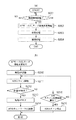
図2(a)、図2(b)は、第1の実施形態におけるデジタルカメラ100の動作を示すフローチャートである。図2(a)に示す処理は、ユーザ操作によって図3の画面301を表示するメニュー操作が行われたことに応じて開始される。また、本フローチャートに示す処理は、デジタルカメラ100の制御部101が入力信号やプログラムに従い、デジタルカメラ100の各部を制御することにより実現される。特に断らない限り、デジタルカメラ100の処理を示す他のフローチャートでも同様である。
FIG. 2A and FIG. 2B are flowcharts showing the operation of the
図3は、第1の実施形態におけるデジタルカメラ100において、ユーザ操作によって表示部106に表示されるメニュー画面からスマートデバイスと無線LAN接続する際の画面遷移図である。
FIG. 3 is a screen transition diagram when the wireless camera is connected to the smart device from the menu screen displayed on the
まず、ステップS201において、制御部101は、無線接続を開始する指示を受け付けたか否かを判断する。制御部101は、図3の画面301を表示部106に表示させ、無線接続を開始するための操作を受け付ける。ユーザは、スマートデバイスと無線接続する機能を実行するためのアイコン(画面301のアイコン350)を、操作部105(例えばタッチパネル)を介して選択することで、スマートデバイスと無線接続する機能を実行する指示を入力することができる。もし、無線接続が開始された場合はステップS202に進み、そうでない場合はステップS201へ進む。
First, in step S201, the
ステップS202において、制御部101は、APモードで動作するかCLモードで動作するかを決定するための自動決定処理を実行する。ここで、ステップS202の自動決定処理について、図2(b)を参照して詳細を説明する。
In step S202, the
図2(b)のステップS210において、制御部101は、簡易APを起動して無線LANネットワークを形成する。具体的には、簡易APを起動してビーコンの発信を開始する。なお、過去に接続したことがあるスマートデバイスが接続する場合、スマートデバイス側で過去に接続した無線LANの通信パラメータ(特にSSID)を履歴情報として保持している場合が多い。その場合は、スマートデバイスはデジタルカメラ100が発信するビーコンを検知することで、保持する履歴と同じ通信パラメータを用いて自動的に無線LAN接続を行うことができる。そこで、前回と同じSSIDを含むビーコンを発信することで、同じSSIDのネットワークを生成してもよい。あるいはネットワークを生成する度にランダムに決定される通信パラメータを利用して、セキュリティ性を向上させてもよい。
In step S210 in FIG. 2B, the
ステップS211において、制御部101は、図3の画面302を表示部106に表示させるとともに、周囲の無線LANネットワークを検索するスキャン動作を実行する。具体的には、周囲の無線LANネットワークが発信するビーコンを検出して、無線LANネットワークの情報を取得する。制御部101は、少なくとも無線LANネットワークの情報として、無線LANネットワークのSSID(Service Set Identifier)を取得する。なお、この間もステップS210での自らのビーコンの発信は継続される。すなわち、ネットワークのスキャン動作と、ビーコンの発信動作とは、並行して実行される。また、ステップS210とステップS211とは、開始する順番が前後してもよい。
In step S211, the
ステップS212において、制御部101は、ステップS211において検索した無線LANネットワークの中に、所望の無線LANネットワークが見つかったかを判断する。所望の無線LANネットワークとは、例えば過去に接続したことのある無線LANネットワークである。この場合は、過去に接続したことのある無線LANネットワークを接続履歴として記録しておき、この履歴と比較して、同じネットワークであれば、所望の無線LANネットワークが見つかったと判断する。あるいは、あらかじめユーザが任意に登録しておいた無線LANネットワークと比較しても良い。なお、所望の無線LANネットワークであるか否かの判断は、ステップS211で取得したSSIDを利用して判断しても良いし、BSSID(Basic Service Set Identidier)などの別の通信パラメータを利用しても良い。もし、所望の無線LANネットワークが見つかった場合はステップS213に進み、そうでない場合はステップS215に進む。
In step S212, the
まず、ステップS212において、ステップS213に進んだ場合について説明する。この場合はCLモードとして動作することが決定される。 First, the case where the process proceeds to step S213 in step S212 will be described. In this case, it is determined to operate as the CL mode.
そのために、ステップS213において、制御部101は、ステップS210で起動した簡易APを終了させ、形成していた無線LANネットワークを破棄する。具体的には、発信していたビーコンを停止させる。また、形成していた無線LANネットワークに他の機器が接続していた場合は、それらの機器に対してDeauth Packetを送信することで、ネットワークからの離脱を促してから無線LANネットワークを破棄する。
Therefore, in step S213, the
ステップS214において、制御部101は、ステップS212で発見した無線LANネットワークに接続する。具体的には、発見したSSIDを持つ無線LANネットワークに対して参加要求を送信し、参加要求に対する受け付けたことを示す信号を受信する。このとき、図3の画面303を表示部106に表示させ、接続しようとしているネットワークのSSIDをユーザに把握させる。もしこの表示を見てユーザが、望むネットワークではないと判断できた場合などに、接続を停止することができるよう、キャンセルボタンも併せて表示される。
In step S214, the
次に、ステップS212において、ステップS215に進んだ場合について説明する。 Next, the case where the process proceeds to step S215 in step S212 will be described.
ステップS215において、制御部101は、ステップS211で無線LANネットワークの検索を所定回数行ったかを判断する。なお、ここで言う1回の検索とは、ビーコンの受信のために所定の時間、待ちうけることを言う。つまり、所定の時間待ちうける動作を、所定回数行ったか否かを判断する。例えば、ステップS211で行う無線LANネットワークの検索処理は、取りこぼしが発生する可能性がある。すなわち、本来検出されるべき無線LANネットワークの情報が、必ずしも取得できる訳ではない。そのため、確実に周囲の無線LANネットワークを検索するためには、何度か無線LANネットワークの検索を実行する必要がある。無線LANネットワークの検索を所定回数行っていない場合は、ステップS211に戻り、検索を繰り返す。一方、無線LANネットワークの検索を所定回数行っても所望のネットワークが見つからなかった場合は、ステップS216に進む。
In step S215, the
ステップS216では、制御部101は、ネットワークの検索を諦め、S211で開始したスキャン動作を停止する。この場合は、APモードとしての動作を継続することになる。
In step S216, the
以上の手順でAPモードで動作するかCLモードで動作するかが決定される。 The procedure described above determines whether to operate in the AP mode or the CL mode.
図2(a)の説明に戻る。 Returning to the description of FIG.
ステップS203において、制御部101は、図3の画面304または305を表示部106に表示させ、接続相手であるスマートデバイスの検索を行う。具体的には、機器検索で用いられるのはディスカバリプロトコルであり、例えば、SSDP(Single Service Discovery Protocol)やMalticast DNSなどを用いることができる。ここでは、ステップS202でAPモードなると決定された場合には、自らが生成したネットワーク内に参加したスマートデバイスを検索する。一方、ステップS202でCLモードになると決定された場合には、外部機器が生成するネットワーク内でスマートデバイスを検索する。なお、ステップS202において、APモードに決定した場合は画面305を、CLモードに決定した場合は画面304となる。
In step S203, the
ステップS204において、制御部101は、図3の画面306を表示部106に表示させ、接続相手であるスマートデバイスとの接続を行う。スマートデバイスとのアプリケーションレベルの接続が完了すると、制御部101は、図3の画面307を表示部106に表示する。この画面では、送信対象となる画像が表示され、画像送信サービスを開始する。
In step S204, the
以上、本実施形態のデジタルカメラ100は、周囲の無線LANネットワークを検索すると共に、自らネットワークを生成する。これにより、ネットワークのスキャンが完了する前に外部機器との通信を始めることも可能となる。
As described above, the
[第2の実施形態]
図4(a)、図4(b)、図5を参照して、第2の実施形態を説明する。ここでは、デジタルカメラ100が利用するサービスが、APモードでは実現できない場合の処理について説明する。なお、デジタルカメラ100の構成は、本発明の第1の実施形態と同様なので説明を省略する。
[Second Embodiment]
The second embodiment will be described with reference to FIG. 4A, FIG. 4B, and FIG. Here, processing when the service used by the
図4(a)、図4(b)は、第2の実施形態におけるデジタルカメラ100の動作を示すフローチャートである。図4(a)に示す処理は、ユーザ操作によって図5の画面501を表示するメニュー操作が行われたことに応じて開始される。
FIG. 4A and FIG. 4B are flowcharts illustrating the operation of the
図5は、第2の実施形態におけるデジタルカメラ100において、ユーザ操作によって表示部106に表示されるメニュー画面からウェブサービスと無線LAN接続する際の画面遷移図である。
FIG. 5 is a screen transition diagram when a wireless LAN connection is established with a web service from a menu screen displayed on the
まず、図4(a)のステップS401において、制御部101は、無線接続を開始する指示を受け付けたか否かを判断する。制御部101は、図5の画面501を表示部106に表示させ、無線接続を開始するための操作を受け付ける。ユーザは、スマートデバイスと無線接続する機能を実行するためのアイコン(画面501のアイコン350)を、操作部105(例えばタッチパネル)を介して選択することで、スマートデバイスと無線接続する機能を実行する指示を入力することができる。更に、ユーザは、ウェブサービスと無線接続する機能を実行するためのアイコン(画面501のアイコン550)を、操作部105(例えばタッチパネル)を介して選択することで、ウェブサービスと無線接続する機能を実行する指示を入力することができる。もし、いずれかのアイコンの選択により無線接続を開始する指示を受け付けた場合はステップS402に進み、そうでない場合はステップS401へ進む。
First, in step S401 of FIG. 4A, the
ステップS402において、制御部101は、これから無線接続するサービス(すなわちステップS401で選択されたサービス)に基づき、APモードを利用することが可能かを判断する。具体的には、ステップS401で選択されたウェブサービスにおいては、ウェブサービスに接続するためにはインターネットに接続する必要がある。しかしながら、自身がAPモードで動作(簡易APとして動作)した場合には、ゲートウェイ機能がないため、ウェブサービスには接続できない。そのため、ウェブサービスを利用するための無線接続の開始を指示された場合には、本ステップにて、APモードで利用できないと判断する。一方、スマートデバイスとの接続の場合は、インターネットに接続する必要はない。自身が簡易APとして動作しても、スマートデバイスがそのネットワークに接続することでサービスの利用が可能である。従って、スマートデバイスとの通信のための無線接続の開始を指示された場合には、本ステップにてAPモードが利用できると判断する。もし、自身が簡易APとして動作して接続することが可能な場合はステップS404に進み、そうでない場合はステップS403に進む。
In step S402, the
まず、ステップS402において、ステップS403に進んだ場合について説明する。 First, a case where the process proceeds to step S403 in step S402 will be described.
ステップS403において、制御部101は、CLモードとして周囲の無線LANネットワークに無線LAN接続する。ここでステップS403の処理について、図4(b)を参照して詳細を説明する。
In step S403, the
図4(b)のステップS410において、制御部101は、図5の画面502を表示部106に表示させ、周囲の無線LANネットワークを検索する。具体的には、周囲の無線LANネットワークが発信するビーコンを検出して、無線LANネットワークの情報を取得する。制御部101は、少なくとも無線LANネットワークの情報として、無線LANネットワークのSSID(Service Set Identifier)を取得する。
In FIG.4 (b) step S410, the
ステップS411において、制御部101は、ステップS410において検索した無線LANネットワークの中に、所望の無線LANネットワークが見つかったかを判断する。所望の無線LANネットワークとは、例えば過去に接続したことのある無線LANネットワークである。この場合は、過去に接続したことのある無線LANネットワークを接続履歴として記録しておき、この履歴と比較して、同じネットワークであれば、所望の無線LANネットワークが見つかったと判断する。あるいは、あらかじめユーザが任意に登録しておいた無線LANネットワークと比較しても良い。なお、所望の無線LANネットワークであるか否かの判断は、ステップS211で取得したSSIDを利用して判断しても良いし、BSSID(Basic Service Set Identidier)などの別の通信パラメータを利用しても良い。もし、所望の無線LANネットワークが見つかった場合はステップS414に進み、そうでない場合はステップS412に進む。
In step S411, the
ステップS412において、制御部101は、ステップS211で無線LANネットワークの検索を所定回数行ったかを判断する。もし、無線LANネットワークの検索を所定回数行った場合はステップS413に進み、そうでない場合はステップS410に進む。
In step S412, the
ステップS413において、制御部101は、図5の画面503を表示部106に表示させ、周囲のアクセスポイントが生成しているネットワークをユーザに把握させると共に、無線LANネットワークを選択する操作を受け付ける。ユーザは、操作部105(例えばタッチパネル)を介して表示されたSSIDを選択することで、所望の無線LANネットワークへの接続を指示する。なお、ここではセキュリティが設定されていない無線LANネットワークを選択した場合について説明するが、セキュリティが設定されている無線LANネットワークを選択した場合はセキュリティキーの入力をユーザに促す。すなわち、ステップS414の前に、PSK(Pre−Shared Key)やWEP(Wired Equivalent Privacy)キーを入力する画面を設ける。
In step S413, the
ステップS414において、制御部101は、図5の画面504を表示部106に表示させ、ステップS411で発見した無線LANネットワークもしくは、ステップS413で選択した無線LANネットワークに接続する。
In step S414, the
図4(a)の説明に戻る。 Returning to the description of FIG.
続くステップS405において、制御部101は、図5の画面505を表示部106に表示させ、ウェブサービスを検索する。具体的には予め定められたURL(Uniform Resource Locator)などを参照して、対応するウェブサービスを検索する。
In subsequent step S405, the
ステップS406において、制御部101は、発見したウェブサービスに対して接続処理を行う。
In step S406, the
以上がステップS402においてAPモードが利用できない場合についての説明である。 This completes the description of the case where the AP mode cannot be used in step S402.
次に、ステップS402において、ステップS404に進んだ場合について説明する。この場合、ステップS406〜ステップS408の処理が実行される。これらの処理は、第1の実施形態で説明した図2のステップS202〜ステップS204と同様の処理が実行される。 Next, the case where the process proceeds to step S404 in step S402 will be described. In this case, the process of step S406-step S408 is performed. These processes are executed in the same manner as steps S202 to S204 in FIG. 2 described in the first embodiment.
以上、本実施形態のデジタルカメラ100は、APモード/CLモードを自動的に決定するか否かを、サービスの種類によって決定する方法について述べた。これにより、APモードでの接続を行ってもサービスを実行できない場合は、CLモードに自動的に決定することが可能となるため、不要な処理をすることなく、よりスムーズに通信を開始することができる。
As described above, the
[第3の実施形態]
図6(a)、図6(b)、図7を参照して、第3の実施形態を説明する。ここでは、近接無線通信に応じて、デジタルカメラ100とスマートデバイスとが無線LAN接続することが可能な場合のAPモード/CLモード自動決定処理について説明する。近接無線通信としては、NFC(Near Field Communication)通信やBluetooth(登録商標)通信が用いられる。なお、デジタルカメラ100の構成は、本発明の第1の実施形態と同様なので説明を省略する。
[Third Embodiment]
The third embodiment will be described with reference to FIGS. 6A, 6B, and 7. FIG. Here, AP mode / CL mode automatic determination processing when the
図6(a)、図6(b)は、第3の実施形態におけるデジタルカメラ100の動作を示すフローチャートである。図6(a)に示す処理は、ユーザ操作によって図3の画面301を表示するメニュー操作が行われたことに応じて開始される。
FIGS. 6A and 6B are flowcharts illustrating the operation of the
ステップS601において、制御部101は、無線接続を開始する指示を受け付けたか否かを判断する。本実施形態では、第1および第2の実施形態で説明した、メニュー画面への操作による指示の他に、近距離無線通信部112を介して、外部装置から無線LANでの接続の開始要求を受け付けることもできる。本ステップでは例えば制御部101は、図7の画面701を表示部106に表示させ、無線接続を開始する指示を受け付ける。無線接続を開始する指示を受信または受け付けた場合は、無線接続を開始する。もし、無線接続が開始された場合はステップS602に進み、そうでない場合はステップS601へ進む。
In step S601, the
ステップS602において、制御部101は、これから接続する無線接続がハンドオーバー接続なのかを判断する。言い換えれば、ステップS601で受け付けた指示が、ユーザからのメニュー画面への操作による指示であるか、近距離無線通信部112を介して外部装置から受け付けた指示であるかを判断する。接続相手であるスマートデバイス等が、Bluetooth(登録商標) Low Energyなどを用いて、デジタルカメラ100の近距離無線通信部112による無線接続の開始要求した場合はハンドオーバー接続であると判断し、ステップS603に進む。ユーザからのメニュー画面への操作による指示である場合、ハンドオーバー接続でないと判断し、ステップS604へ進む。
In step S602, the
まずハンドオーバー接続であると判断した場合について説明する。 First, a case where it is determined that the connection is a handover connection will be described.
この場合、ステップS603において、制御部101は、図7の画面702を表示部106に表示させ、簡易APを起動して無線LANネットワークを形成する。なお、ここで起動する簡易APの無線LANパラメータは、ステップS602の無線接続の開始要求に応じて、あらかじめ接続相手であるスマートデバイス等に近距離無線通信部112を介して、通知しておいても良い。このようにすることで、接続相手であるスマートデバイスは、簡単にデジタルカメラ100の形成する簡易APに接続することが可能となる。
In this case, in step S603, the
一方、ハンドオーバー接続でないと判断した場合は以下の動作を行う。 On the other hand, when it is determined that the connection is not a handover connection, the following operation is performed.
ステップS604において、制御部101は、APモードで動作するかCLモードで動作するかを決定する。ここで、ステップS604の自動決定処理について、図6(b)を参照して詳細を説明する。
In step S604, the
図6(b)のステップS610において、制御部101は、簡易AP機能を起動して無線LANネットワークを形成する。本ステップの処理は図2のステップS210と同様である。
In step S610 of FIG. 6B, the
ステップS611において、制御部101は、周囲の無線LANネットワークを検索する。本ステップの処理は図2のステップS211と同様である。ステップS611の実行中でも、ステップS610で開始したビーコンの発信は継続される。すなわち、ネットワークのスキャン動作と、ビーコンの発信動作とは、並行して実行される。図2での説明と同様にステップS610とステップS611の実行開始の順番は前後してもよい。制御部101は、S611で開始したネットワークのスキャンを終了して、APモード/CLモード自動決定処理を終了する。そうでない場合はステップS613に進む。
In step S611, the
ステップS612において、制御部101は、ステップS611において検索した無線LANネットワークの中に、所望の無線LANネットワークが見つかったかを判断する。もし、所望の無線LANネットワークが見つかった場合はステップS613に進み、そうでない場合はステップS615に進む。ここでいう所望のネットワークは図2のステップS212の説明で述べたものと同様である。
In step S612, the
まず、ステップS613に進んだ場合について説明する。 First, the case where it progresses to step S613 is demonstrated.
ステップS613において、制御部101は、ステップS610で起動した簡易APを終了させ、形成していた無線LANネットワークを破棄する。具体的には、発信していたビーコンを停止させる。また、形成していた無線LANネットワークに他の機器が接続していた場合は、それらの機器に対してDeauth Packetを送信することで、ネットワークからの離脱を促してから無線LANネットワークを破棄する。
In step S613, the
ステップS614において、制御部101は、ステップS611で発見した無線LANネットワークに接続する。具体的には、発見したSSIDを持つ無線LANネットワークに対して参加要求を送信し、参加要求に対する受け付けたことを示す信号を受信する。その後、APモード/CLモード自動決定処理を終了する。
In step S614, the
次にステップS615に進んだ場合について説明する。 Next, the case where it progresses to step S615 is demonstrated.
ステップS615において、制御部101は、ステップS610で形成した無線LANネットワークに、CL機器が参加したかを判断する。形成した無線LANネットワークに、CL機器が参加してきた場合は、ステップS616に進む。そうでない場合はステップS617に進む。
In step S615, the
ステップS616に進んだ場合は、制御部101は、S611で開始したネットワークのスキャンを終了して、APモード/CLモード自動決定処理を終了する。
When the process proceeds to step S616, the
一方、ステップS617に進んだ場合は、制御部101は、ステップS611で無線LANネットワークの検索を所定回数行ったかを判断する。なお、ここで言う1回の検索とは、ビーコンの受信のために所定の時間、待ちうけることを言う。つまり、所定の時間待ちうける動作を、所定回数行ったか否かを判断する。無線LANネットワークの検索を所定回数行っていない場合は、ステップS211に戻り、検索を繰り返す。一方、無線LANネットワークの検索を所定回数行っても所望のネットワークが見つからなかった場合は、ステップS616に進み、スキャン動作を停止し、APモード/CLモード自動決定処理を終了する。
On the other hand, when the process proceeds to step S617, the
以上のように、APモード/CLモード自動決定処理では、所望の無線LANネットワークが見つかった場合はCLモードに決定する。また、所望の無線LANネットワークが見つからない場合、または所望の無線LANネットワークが見つかる前に、形成した無線LANネットワークにCL機器が参加した場合はAPモードに決定する。 As described above, in the AP mode / CL mode automatic determination process, when a desired wireless LAN network is found, the CL mode is determined. If a desired wireless LAN network is not found, or if a CL device participates in the formed wireless LAN network before the desired wireless LAN network is found, the AP mode is determined.
図6(a)の説明に戻る。 Returning to the description of FIG.
ステップS605において、制御部101は、図7の画面703を表示部106に表示させ、接続相手であるスマートデバイスの検索を行う。
In step S605, the
ステップS606において、制御部101は、接続相手であるスマートデバイスとの接続を行う。スマートデバイスとのアプリケーションレベルの接続が完了すると、制御部101は、図7の画面704を表示部106に表示する。この画面では、送信対象となる画像が表示され、画像送信サービスを開始する。
In step S606, the
以上、本実施形態のデジタルカメラ100は、APモード/CLモードを自動的に決定するか否かを、接続方法によって決定する方法について述べた。これにより、あらかじめ形成する無線LANネットワークの情報を受け渡しできる場合は、APモードに自動的に決定することが可能となる。
As described above, the
[その他の実施形態]
本発明は、上述の実施形態の1以上の機能を実現するプログラムを、ネットワーク又は記憶媒体を介してシステム又は装置に供給し、そのシステム又は装置のコンピュータにおける1つ以上のプロセッサーがプログラムを読出し実行する処理でも実現可能である。また、1以上の機能を実現する回路(例えば、ASIC)によっても実現可能である。
[Other Embodiments]
The present invention supplies a program that realizes one or more functions of the above-described embodiments to a system or apparatus via a network or a storage medium, and one or more processors in a computer of the system or apparatus read and execute the program This process can be realized. It can also be realized by a circuit (for example, ASIC) that realizes one or more functions.
Claims (9)
無線通信手段と、
前記無線通信手段により中継装置が形成したネットワークをスキャンするスキャン手段と、
前記中継装置が形成したネットワークに前記無線通信手段を介して参加する参加手段と、
前記無線通信手段を用いて前記通信装置が中継装置となりネットワークを形成する形成手段と、
前記スキャン手段と、前記形成手段を並行して動作させるよう制御する制御手段とを有し、
前記スキャン手段と前記形成手段とが並行して動作している状態で、所定のネットワークが前記スキャン手段により発見された場合、前記制御手段は、前記形成手段で形成したネットワークを破棄すると共に、前記参加手段により、前記所定のネットワークに参加するよう制御することを特徴とした通信装置。 In a communication device that communicates with an external device by wireless communication,
Wireless communication means;
Scanning means for scanning the network formed by the relay device by the wireless communication means;
Participation means for participating in the network formed by the relay device via the wireless communication means;
Forming means for forming a network by using the wireless communication means and the communication device becomes a relay device;
The scanning means, and a control means for controlling the forming means to operate in parallel,
When a predetermined network is found by the scanning unit in a state where the scanning unit and the forming unit are operating in parallel, the control unit discards the network formed by the forming unit, and A communication apparatus that controls to participate in the predetermined network by a joining means.
前記所定のネットワークは、過去に接続したことのあるネットワークと同じ情報を有するネットワークであることを特徴とする請求項1または2に記載の通信装置。 It further has means for holding information about networks connected in the past,
The communication apparatus according to claim 1, wherein the predetermined network is a network having the same information as a network that has been connected in the past.
前記検知手段が前記形成手段で形成したネットワークに他の通信装置が参加したことを検知した場合、前記制御手段は、前記スキャン手段を停止するよう制御することを特徴とする請求項1乃至3のいずれか1項に記載の通信装置。 It further comprises detection means for detecting that another communication device has joined the network formed by the formation means,
4. The control unit according to claim 1, wherein when the detection unit detects that another communication device has joined the network formed by the forming unit, the control unit controls the scanning unit to stop. The communication apparatus of any one of Claims.
前記制御手段は、前記受け付け手段により前記ネットワークを介して実行するサービスの指示をユーザから受け付けたことに応じて、前記実行を指示されたサービスの種類に基づき、前記スキャン手段と前記形成手段を並行して動作させるか否かを判断することを特徴とする請求項1乃至4のいずれか1項に記載の通信装置。 A receiving unit that receives an instruction of a service to be executed from the user via the network;
The control means executes the scanning means and the forming means in parallel based on the type of service instructed to execute in response to receiving an instruction from the user by the accepting means for the service to be executed via the network. The communication apparatus according to claim 1, wherein it is determined whether or not to operate the communication apparatus.
前記第二の無線通信手段を介して外部装置から通信を開始する指示を受け付けた場合、前記制御手段は、前記スキャン手段を動作させず、前記形成手段を動作させるよう制御することを特徴とする請求項1乃至5のいずれか1項に記載の通信装置。 A second wireless communication means different from the wireless communication means;
When receiving an instruction to start communication from an external device via the second wireless communication unit, the control unit controls the forming unit to operate without operating the scanning unit. The communication apparatus according to any one of claims 1 to 5.
前記無線通信手段により中継装置が形成したネットワークをスキャンするスキャンステップと、
中継装置が形成したネットワークに前記無線通信手段を介して参加する参加ステップと、
前記無線通信手段を用いて前記通信装置が中継装置となりネットワークを形成する形成ステップと、
前記スキャンステップと、前記形成ステップを並行して実行する制御ステップとを有し、
前記スキャンステップと前記形成ステップとが並行して実行されている状態で、所定のネットワークが前記スキャンステップにより発見された場合、前記形成ステップで形成したネットワークを破棄すると共に、前記参加ステップを実行することにより、前記所定のネットワークに参加するよう制御することを特徴とした通信装置の制御方法。 A method for controlling a communication device having a wireless communication means for communicating with an external device by wireless communication,
A scanning step of scanning a network formed by a relay device by the wireless communication means;
A joining step of joining via a wireless communication means to a network formed by a relay device;
A forming step in which the communication device becomes a relay device and forms a network using the wireless communication means;
The scanning step, and a control step for executing the forming step in parallel,
When a predetermined network is discovered by the scanning step in a state where the scanning step and the forming step are executed in parallel, the network formed in the forming step is discarded and the joining step is executed. Thus, a control method for a communication apparatus, wherein control is performed so as to participate in the predetermined network.
Priority Applications (1)
| Application Number | Priority Date | Filing Date | Title |
|---|---|---|---|
| JP2016191329A JP6918463B2 (en) | 2016-09-29 | 2016-09-29 | Communication equipment, its control method, and programs |
Applications Claiming Priority (1)
| Application Number | Priority Date | Filing Date | Title |
|---|---|---|---|
| JP2016191329A JP6918463B2 (en) | 2016-09-29 | 2016-09-29 | Communication equipment, its control method, and programs |
Publications (2)
| Publication Number | Publication Date |
|---|---|
| JP2018056829A true JP2018056829A (en) | 2018-04-05 |
| JP6918463B2 JP6918463B2 (en) | 2021-08-11 |
Family
ID=61837304
Family Applications (1)
| Application Number | Title | Priority Date | Filing Date |
|---|---|---|---|
| JP2016191329A Active JP6918463B2 (en) | 2016-09-29 | 2016-09-29 | Communication equipment, its control method, and programs |
Country Status (1)
| Country | Link |
|---|---|
| JP (1) | JP6918463B2 (en) |
Cited By (2)
| Publication number | Priority date | Publication date | Assignee | Title |
|---|---|---|---|---|
| JP2020099025A (en) * | 2018-12-19 | 2020-06-25 | Necプラットフォームズ株式会社 | Wireless master device, wireless relay device, wireless communication system, wireless communication method, and program |
| JP2023179890A (en) * | 2022-06-08 | 2023-12-20 | キヤノン株式会社 | Communication device, control method and program for communication device |
Citations (2)
| Publication number | Priority date | Publication date | Assignee | Title |
|---|---|---|---|---|
| JP2014131103A (en) * | 2012-12-28 | 2014-07-10 | Canon Inc | Communication apparatus, control method thereof, and program |
| JP2015220569A (en) * | 2014-05-16 | 2015-12-07 | キヤノン株式会社 | Communication device, control method, and program |
-
2016
- 2016-09-29 JP JP2016191329A patent/JP6918463B2/en active Active
Patent Citations (2)
| Publication number | Priority date | Publication date | Assignee | Title |
|---|---|---|---|---|
| JP2014131103A (en) * | 2012-12-28 | 2014-07-10 | Canon Inc | Communication apparatus, control method thereof, and program |
| JP2015220569A (en) * | 2014-05-16 | 2015-12-07 | キヤノン株式会社 | Communication device, control method, and program |
Cited By (3)
| Publication number | Priority date | Publication date | Assignee | Title |
|---|---|---|---|---|
| JP2020099025A (en) * | 2018-12-19 | 2020-06-25 | Necプラットフォームズ株式会社 | Wireless master device, wireless relay device, wireless communication system, wireless communication method, and program |
| JP2023179890A (en) * | 2022-06-08 | 2023-12-20 | キヤノン株式会社 | Communication device, control method and program for communication device |
| JP7596331B2 (en) | 2022-06-08 | 2024-12-09 | キヤノン株式会社 | COMMUNICATION DEVICE, CONTROL METHOD AND PROGRAM FOR COMMUNICATION DEVICE |
Also Published As
| Publication number | Publication date |
|---|---|
| JP6918463B2 (en) | 2021-08-11 |
Similar Documents
| Publication | Publication Date | Title |
|---|---|---|
| US9451527B2 (en) | Communication apparatus, control method, and program | |
| US11089481B2 (en) | Communication apparatus communicating with external apparatus in a selected procedure from among a plurality of procedures to establish wireless connection, control method for communication apparatus, and recording medium | |
| US9843999B2 (en) | Communication apparatus, method for controlling the same, and computer-readable recording medium | |
| JP6400101B2 (en) | COMMUNICATION DEVICE, COMMUNICATION DEVICE CONTROL METHOD, PROGRAM | |
| US9807222B2 (en) | Communication apparatus, method of controlling same, and storage medium | |
| US10015262B2 (en) | Communication apparatus and control method thereof | |
| JP6092622B2 (en) | COMMUNICATION DEVICE, ITS CONTROL METHOD, PROGRAM | |
| US10257337B2 (en) | Communication apparatus connectable with use of close proximity wireless communication, method for controlling communication apparatus, and recording medium | |
| JP7175634B2 (en) | Communication device, control method and program | |
| JP6385078B2 (en) | COMMUNICATION DEVICE, COMMUNICATION DEVICE CONTROL METHOD, PROGRAM | |
| JP6415232B2 (en) | COMMUNICATION DEVICE, COMMUNICATION DEVICE CONTROL METHOD, PROGRAM | |
| JP6399854B2 (en) | COMMUNICATION DEVICE, COMMUNICATION DEVICE CONTROL METHOD, PROGRAM | |
| JP6033014B2 (en) | Information processing apparatus, control method thereof, and program | |
| JP6918463B2 (en) | Communication equipment, its control method, and programs | |
| JP2018033002A (en) | Wireless communication apparatus, control method of the same, and wireless communication system | |
| JP6650793B2 (en) | Communication device, communication device control method, and program | |
| JP7703339B2 (en) | COMMUNICATION DEVICE, CONTROL METHOD, AND PROGRAM | |
| JP6433231B2 (en) | COMMUNICATION DEVICE, COMMUNICATION DEVICE CONTROL METHOD, PROGRAM | |
| JP2018142865A (en) | Communication device, control method of communication device, and program | |
| JP6386862B2 (en) | COMMUNICATION DEVICE, COMMUNICATION DEVICE CONTROL METHOD, PROGRAM | |
| JP2016025374A (en) | COMMUNICATION DEVICE, COMMUNICATION DEVICE CONTROL METHOD, PROGRAM | |
| JP2018107714A (en) | Communication device, control method of communication device, and program | |
| JP2016100724A (en) | Information processing apparatus, information processing method, and program | |
| CN118160402A (en) | Wireless communication device and control method thereof | |
| JP2014131107A (en) | Radio communication apparatus, control method thereof, and program |
Legal Events
| Date | Code | Title | Description |
|---|---|---|---|
| A621 | Written request for application examination |
Free format text: JAPANESE INTERMEDIATE CODE: A621 Effective date: 20190926 |
|
| A977 | Report on retrieval |
Free format text: JAPANESE INTERMEDIATE CODE: A971007 Effective date: 20200529 |
|
| A131 | Notification of reasons for refusal |
Free format text: JAPANESE INTERMEDIATE CODE: A131 Effective date: 20201006 |
|
| A521 | Request for written amendment filed |
Free format text: JAPANESE INTERMEDIATE CODE: A523 Effective date: 20201203 |
|
| A131 | Notification of reasons for refusal |
Free format text: JAPANESE INTERMEDIATE CODE: A131 Effective date: 20210224 |
|
| A521 | Request for written amendment filed |
Free format text: JAPANESE INTERMEDIATE CODE: A523 Effective date: 20210416 |
|
| TRDD | Decision of grant or rejection written | ||
| A01 | Written decision to grant a patent or to grant a registration (utility model) |
Free format text: JAPANESE INTERMEDIATE CODE: A01 Effective date: 20210622 |
|
| A61 | First payment of annual fees (during grant procedure) |
Free format text: JAPANESE INTERMEDIATE CODE: A61 Effective date: 20210721 |
|
| R151 | Written notification of patent or utility model registration |
Ref document number: 6918463 Country of ref document: JP Free format text: JAPANESE INTERMEDIATE CODE: R151 |