JP2018050650A - Connection component for wearable apparatus and wearable apparatus - Google Patents
Connection component for wearable apparatus and wearable apparatus Download PDFInfo
- Publication number
- JP2018050650A JP2018050650A JP2016186475A JP2016186475A JP2018050650A JP 2018050650 A JP2018050650 A JP 2018050650A JP 2016186475 A JP2016186475 A JP 2016186475A JP 2016186475 A JP2016186475 A JP 2016186475A JP 2018050650 A JP2018050650 A JP 2018050650A
- Authority
- JP
- Japan
- Prior art keywords
- wearable device
- connector
- living body
- housing
- electronic device
- Prior art date
- Legal status (The legal status is an assumption and is not a legal conclusion. Google has not performed a legal analysis and makes no representation as to the accuracy of the status listed.)
- Granted
Links
Images


Landscapes
- Measurement And Recording Of Electrical Phenomena And Electrical Characteristics Of The Living Body (AREA)
Abstract
【課題】物理的に身体へ与える圧迫感や痛みなどの負担を軽減するウエアラブル機器用接続部品を提供する。【解決手段】ウエアラブル機器用接続部品は、柔軟な素材からなる生体対向面を備えた筐体と、端子が生体対向面以外の方向に露出したコネクタとを有する。この構成では、人体などの生体に直接的または間接的に接触する生体対向面が柔軟であるため、物理的に生体に与える圧迫感や痛みなどの負担を軽減するウエアラブル機器用接続部品を提供することができる。【選択図】 図1PROBLEM TO BE SOLVED: To provide a connection component for a wearable device which reduces a burden such as a feeling of pressure and pain physically given to a body. A connector for a wearable device includes a housing provided with a living body facing surface made of a flexible material, and a connector whose terminals are exposed in a direction other than the living body facing surface. In this configuration, since the living body facing surface that comes into direct or indirect contact with the living body such as the human body is flexible, a connection component for a wearable device that physically reduces the burden of pressure and pain on the living body is provided. be able to. [Selection diagram] Fig. 1
Description
本発明は、ウエアラブル機器用接続部品およびウエアラブル機器に関する。 The present invention relates to a wearable device connection part and a wearable device.
人体が身に着けたウエアラブルセンサによって生体情報を計測する装置が開発されている。例えば、特許文献1には、インナーシャツに分散して配置された複数のセンサと、インナーシャツに配置されセンサの信号を伝送する配線と、配線を通じて受信した生体信号を処理する生体信号処理回路とを有する生体情報収集装置の技術が開示されている。
An apparatus for measuring biological information using a wearable sensor worn by a human body has been developed. For example,
特許文献1のような技術を利用する場合には、センサや配線などが着用者に違和感を与えないようにすることが望ましい。それを実現可能とする技術として、今般では、高い導電性としなやかさを併せ持つ生地が開発されている(例えば非特許文献1)。このような生地を利用することにより、センサや電極が身体へ及ぼす違和感を軽減することができる。また、このような生地を用いて作製されたウエアに、通信用電子機器をスナップボタンで接続固定する衣服型デバイスなども開発されている(例えば非特許文献2)。
When using a technique such as
しかしながら、しなやかなセンサやウエアにスナップボタンで通信用電子機器を接続する方法では、通信用電子機器が硬質であるため、計測時に身体への違和感が残るという問題がある。また、全身の筋電を取得するなどセンシング対象を増やす場合は、スナップボタンの数が増えデバイスが大型になるため、違和感がさらに増大する。 However, in the method of connecting a communication electronic device to a supple sensor or wear with a snap button, the communication electronic device is hard, so that there is a problem that a sense of incongruity to the body remains during measurement. Further, when the number of sensing targets is increased, for example, by acquiring myoelectricity of the whole body, the number of snap buttons is increased and the device becomes large, so that the uncomfortable feeling is further increased.
本発明は、上記の問題点に鑑みてなされたものであり、物理的に身体へ与える圧迫感や痛みなどの負担を軽減するウエアラブル機器用接続部品を提供することを目的としている。 The present invention has been made in view of the above-described problems, and an object of the present invention is to provide a wearable device connection part that reduces the burden of pressure, pain, and the like physically applied to the body.
上記の課題を解決するため、ウエアラブル機器用接続部品は、柔軟な素材からなる生体対向面を備えた筐体と、端子が生体対向面以外の方向に露出したコネクタとを有する。 In order to solve the above-described problems, the wearable device connection component includes a housing having a living body facing surface made of a flexible material, and a connector in which a terminal is exposed in a direction other than the living body facing surface.
本発明の効果は、物理的に身体へ与える圧迫感や痛みなどの負担を軽減するウエアラブル機器用接続部品を提供できることである。 An effect of the present invention is that it is possible to provide a connection part for a wearable device that reduces the burden of pressure, pain, and the like physically applied to the body.
以下、図面を参照しながら、本発明の実施形態を詳細に説明する。但し、以下に述べる実施形態には、本発明を実施するために技術的に好ましい限定がされているが、発明の範囲を以下に限定するものではない。なお各図面の同様の構成要素には同じ番号を付し、説明を省略する場合がある。 Hereinafter, embodiments of the present invention will be described in detail with reference to the drawings. However, the preferred embodiments described below are technically preferable for carrying out the present invention, but the scope of the invention is not limited to the following. In addition, the same number is attached | subjected to the same component of each drawing, and description may be abbreviate | omitted.
(第1の実施形態)
図1は、第1の実施形態のウエアラブル機器用接続部品1を示す側面図である。ウエアラブル機器用接続部品1は、柔軟な素材からなる生体対向面10aを備えた筐体10と、端子21が生体対向面10a以外の方向に露出したコネクタ20とを有する。
(First embodiment)
FIG. 1 is a side view showing a wearable
筐体10は、例えば、電子機器30を収納することができる。電子機器30は例えば、コネクタ20を介して受信した信号を処理したり、外部に送信したりするものである。そして、例えば、基板31に電子部品32を実装し、接続部材33を介してコネクタ20の端子21と電気的に接続する構成とすることができる。
The
コネクタ20は相手側コネクタ40と接続することができる。相手側コネクタ40は、例えば、コネクタ20の端子21と接続する相手側端子41と、相手側端子41と外部の電子装置との電気的な接点となる相手側外部端子42とを有するものである。
The
以上説明した本実施形態によれば、人体などの生体に直接的または間接的に接触する生体対向面が柔軟であるため、物理的に生体に与える圧迫感や痛みなどの負担を軽減するウエアラブル機器用接続部品を提供することができる。 According to the present embodiment described above, since the living body facing surface that directly or indirectly contacts a living body such as a human body is flexible, the wearable device that reduces a burden such as a feeling of pressure or pain physically applied to the living body. Connection parts can be provided.
(第2の実施形態)
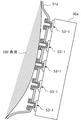
図2は、ウエアラブル機器用接続部品1の用途の一例であるウエアラブル機器50を示す斜視図である。ウエアラブル機器50は、ウエア51と、ウエアラブル機器用接続部品1と、相手側コネクタ40とを有している。
(Second Embodiment)
FIG. 2 is a perspective view showing a wearable device 50 which is an example of an application of the wearable
ウエア51は、例えば、上半身に着用できるように、身体を収納し、頭を通す開口を有する胴部と、上肢を通す袖部とを有する。ウエア51には、生体情報を得るための複数のセンサケーブル52が接着や縫合によって設置されている。センサケーブル52は相手側コネクタ40に接続し、相手側コネクタ40はウエアラブル機器用接続部品1に接続している。こうして、センサケーブル52は、ウエアラブル機器用接続部品1に収容された電子機器(図示せず)に電気的に接続している。
The
この構成では、ウエアラブル機器用接続部品1の生体対向面10aがウエア61の身体側に向く。本実施形態では生体対向面10aが柔軟であるため、人がウエア51を着用した場合に、ウエアラブル機器用接続部品1が人に圧迫感や痛みを与えることがない。図2の例では、センサケーブル52の数を10として、10接点の接続を行っているが、接点の数がさらに増えても問題なく、同様の効果を得ることができる。
In this configuration, the living
センサケーブル52は、配線として利用することができる。この場合、所望の身体箇所に電極を設置して身体に流れる微量の電流を検知したり、各種のセンサの信号をウエアラブル機器用接続部品1に収容された電子機器に集めたりすることができる。また、センサケーブル52自体の電気抵抗が伸縮や体温によって変化することを利用してセンシングを行うこともできる。図示しない電子機器は、例えば、センサケーブル52から受信した電気抵抗や電流などの信号を、内蔵したマイコンで処理し、姿勢や体温、心電や筋電などの生体情報を取得することができる。そして、取得した情報は電子機器内で演算処理され、内蔵メモリに蓄積したり、無線回路でサーバやスマートフォンなどに送ったりすることができる。なお、ウエア51は、下半身を収納する、または全身を収納する形態であってもよい。
The
以上説明したように、本実施形態によれば、利用者が圧迫感や痛みを感じることなく、ウエアラブル機器を利用することができる。
<比較例>
上述したように本実施形態によれば、多数の配線を接続する構成としても人が圧迫感や痛みを感じることがない、一方、一般的な技術を用いた場合は、接点が増えることで人が感じる圧迫感や痛みが増大するという問題がある。比較例を用いて、この問題を説明する。
As described above, according to the present embodiment, the wearable device can be used without causing the user to feel pressure or pain.
<Comparative example>
As described above, according to the present embodiment, even if a configuration in which a large number of wirings are connected, a person does not feel pressure or pain. On the other hand, when a general technique is used, the number of contacts increases. There is a problem of increasing the feeling of pressure and pain felt by people. This problem will be described using a comparative example.
図3は、センサケーブル52と電子機器との一般的な接続方法であるスナップボタン53を用いたウエアラブル機器50aの構成を示す斜視図である。センサケーブル52aが電子機器に接続する接点の数は図2と同様に10としている。なお、ここでは、電子機器を外した状態を示している。
FIG. 3 is a perspective view showing a configuration of a wearable device 50a using a snap button 53, which is a general connection method between the
図4はスナップボタン53を用いた接続構造を示す断面図である。電子機器30a側にはバネ33aが設けられている。バネ33aは配線34aに接続して、電子機器30aの回路と電気的に接続する。ウエア51a側には、ゲンコ53aとホソ53bとが、ウエア51aとセンサケーブル52aとを挟む形で、設けられている。ゲンコ53aがバネ33aに嵌合することにより、センサケーブル52aと電子機器30aの回路とが電気的に接続される。
FIG. 4 is a cross-sectional view showing a connection structure using the snap button 53. A spring 33a is provided on the
図5は、図3のようにスナップボタン53を5×2列で配置した時の接続の様子を示す断面図である。5つのスナップボタン53_1―5が電子機器30aのバネ33aに嵌合している。身体100の断面が曲線であるのに対し、電子機器30aの断面が直線状であるため、この例では、スナップボタン53_1、4、5が浮いてしまっている。このため、ウエア51aが引っ張られるとともに、スナップボタン53_3の部分かかる荷重が大きくなっている。その結果、身体100が受けるストレスが大きくなっている。
FIG. 5 is a cross-sectional view showing a connection state when the snap buttons 53 are arranged in 5 × 2 rows as shown in FIG. Five snap buttons 53_1-5 are fitted to the spring 33a of the
以上説明したように、一般的な技術を用いた場合は、接続点数が増えるほど、圧迫感、痛み、違和感などが生じやすくなる。また、接続に手間がかかり、付け忘れや、確実に接続されないなど、接続失敗や接続外れが起きやすくなる。一方で、本実施形態では、接続点数が増えても痛みや違和感を生じることがない。さらに、コネクタで各接点を正確に接続できるため、接続の失敗や間違いを生じることがない。 As described above, when a general technique is used, as the number of connection points increases, a feeling of pressure, pain, discomfort, and the like are likely to occur. Also, it takes time to connect, and connection failure or disconnection is likely to occur, such as forgetting to attach or not being surely connected. On the other hand, in this embodiment, even if the number of connection points increases, no pain or uncomfortable feeling occurs. Furthermore, since each contact can be accurately connected by a connector, connection failure or mistake does not occur.
(第3の実施形態)
第1の実施形態で説明したように、ウエアラブル機器用接続部品1では、筐体10の生体対向面10aが柔軟であり、コネクタ20の端子21が生体対向面10a以外の方向に露出していればよい。このため、筐体10の形態には、種々のバリエーションが可能である。図6は、その一例を示す側面図である。この例では雄の端子21aを有するコネクタ20aが、生体対向面10aと直角な方向に露出している。また、雌の端子21bを有するコネクタ20bが20aと反対の面から露出している。
(Third embodiment)
As described in the first embodiment, in the wearable
図7は、別の例を示す断面図である。筐体10は柔軟な素材からなる体側筐体11と外側筐体12とに分割されており、接合部で接合されている。接合部には凹凸箇所が設けられ、体側筐体11と外側筐体12とが嵌合し、接着などにより接合され、電子機器30を包み込んでいる。コネクタ20は生体対向面10aの反対側に設けられた外側筐体12の開口部に埋設されている。
FIG. 7 is a cross-sectional view showing another example. The
筐体10を形成する素材には、例えば、各種のゴムや、スポンジなどを用いることができる。これらのゴムやスポンジには非常に多くの種類があり、様々なものを利用できる。好適な素材の例としては、例えば、シリコーンゴムやポリビニルアルコールスポンジなどがある。
As a material for forming the
電子機器30は、機能別に分割されて電子部品32を搭載した硬質な基板31や電池35などが、可撓性を有する接続部材によって電気的に接続されている。基板31は、例えば、マイコン、メモリ、無線回路やアンテナなどの機能を搭載している。
In the
電子機器30は、筐体10内の空間を動けるように筐体10とは固定されていないが、体側筐体11、外側筐体12、それぞれの内側に設けられた柔軟な支柱13によって支えられている。また、基板31と電池35との間など所定の場所には隔壁14を設けて、それぞれの部品が干渉することがないようにしている。上記の構成とすることで、体側筐体11とともに、電子機器30も人体などの生体のラインに無理なく倣うことができ、生体の局所に負荷が集中することがなくなる。
The
図8は外側筐体12aが可撓性を有する素材でできている例を示す断面図である。その他の構成要素は図7の例と同様である。すなわち体側筐体11aは柔軟性を有し、電子機器30は体側筐体11aの変形に倣うことができるようになっている。外側筐体12aは、体側筐体11aの変形に倣うことができれば、このように、必ずしも柔軟性を有していなくても良い。
FIG. 8 is a sectional view showing an example in which the outer casing 12a is made of a flexible material. Other components are the same as in the example of FIG. That is, the body side casing 11a has flexibility, and the
以上、説明したように、本実施形態によれば、利用者の負担軽減と電子機器などの内容物の保護とを両立するウエアラブル機器用接続部品を構成することができる。 As described above, according to the present embodiment, it is possible to configure a wearable device connection part that achieves both reduction of the burden on the user and protection of contents such as an electronic device.
(第4の実施形態)
図9はセンサケーブル52を有するウエア51とウエアラブル機器用接続部品1とを接続したウエアラブル機器を身体100に装着した例を示す断面図である。
(Fourth embodiment)
FIG. 9 is a cross-sectional view showing an example in which a wearable device in which a
ウエア51は、センサケーブル52に接続した相手側コネクタ40を保持し、ウエアラブル機器用接続部品1のコネクタ20が相手側コネクタ40に接続している。図示はしていないが、ウエアラブル機器用接続部品1の筐体10の内部にはコネクタ20と電気的に接続する電子機器が収納されている。センサケーブル52と相手側コネクタ40の相手側外部端子42とは、導電性接着剤54で接続されている。
The
ウエアラブル機器用接続部品1はウエア51と、身体100とに挟まれるように配置されている。2つのコネクタの嵌合は、ウエアラブル機器用接続部品1とウエア51とを電気的、物理的に固定する役割を持つが、ウエア51との固定力が不足する場合は、面ファスナなどをウエアラブル機器用接続部品1の両端に取り付けて固定を補助してもよい。
The wearable
このように、身体100のラインに倣い易い柔軟な生体対向面10aを身体に向け、違和感の元となるコネクタ20を身体の外向きに配置することで、身体に与える違和感を軽減することが可能となる。
As described above, the flexible living
(第5の実施形態)
図10は、本実施形態のウエアラブル機器を身体100に装着した例を示す断面図である。本実施形態の筐体10_1は、生体対向面10a_1が凹凸を有している。その他の構成については第4の実施形態と同様である。
(Fifth embodiment)
FIG. 10 is a cross-sectional view showing an example in which the wearable device according to the present embodiment is mounted on the
凹凸を持つ生体対向面10a_1により通気性が増し、汗の放散効果が得られる。これにより、蒸れによる違和感を更に軽減することができる。なお生体対向面10a_1の凹凸は、例えば、多角形や円形の柱状体を配置してもよいし、多角形や円形の断面形状をしたスリットを設けてもよい。 The living body facing surface 10a_1 having the unevenness increases air permeability and provides a sweat dissipation effect. Thereby, the uncomfortable feeling due to stuffiness can be further reduced. The unevenness of the living body facing surface 10a_1 may be provided with, for example, a polygonal or circular columnar body or a slit having a polygonal or circular cross-sectional shape.
(第6の実施形態)
ここではウエア51と相手側コネクタ40とコネクタ20との接続の具体例を説明する。図11はコネクタ20cと相手側コネクタ40あの接続部近傍の具体例を示す断面図である。
(Sixth embodiment)
Here, a specific example of connection between the
センサケーブル52がウエア51に接着や縫合によって固定されている。センサケーブル52は導電性接着剤54によって相手側外部端子42aに接続されている。コネクタ20cはスプリング端子21cを有し、スプリング端子21cは相手側コネクタ40aの相手側端子41aと電気的に接続している。コネクタ20cは筐体10の段差部に係止されている。
The
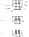
図12は、スプリング端子21cを有するコネクタ20cと相手側コネクタ40aの嵌合構造の例を表す断面図である。コネクタ20cはスプリング端子21cと爪22cとを有している。相手側コネクタ40aは相手側端子41aと、爪22cに嵌合する段差43aとを有している。図12(a)は、コネクタ20cと相手側コネクタ40aとが離れた状態を示している。図12(b)は、爪22aが、相手側コネクタ40aに押し当てられ、押し当てられるに従って開いている状態を示している。図12(c)は、コネクタ20cが、一定量まで押し込まれて相手側コネクタ40aの段差43aに爪22c先端が嵌り、コネクタ20cと相手側コネクタ40aとが電気的に接続され、物理的に固定された状態を示している。
FIG. 12 is a cross-sectional view illustrating an example of a fitting structure between the connector 20c having the spring terminal 21c and the
以上説明したように、本実施形態によれば、ウエアラブル機器用接続部品のコネクタと相手側コネクタとを確実に接続することができる。 As described above, according to the present embodiment, the connector of the connecting part for wearable device and the counterpart connector can be reliably connected.
(第7の実施形態)
第4、第5の実施形態では、ウエアラブル機器用接続部品と身体とが直接接触するウエアラブル機器の例について説明したが、両者の間にウエアを介在させても良い。
(Seventh embodiment)
In the fourth and fifth embodiments, the example of the wearable device in which the connecting part for the wearable device and the body are in direct contact with each other has been described, but the wear may be interposed therebetween.
図13は、ウエア51がウエアラブル機器用接続部品1を収納する袋部55を備えるウエアラブル機器の例を示す断面図である。袋部55を設けたことで、身体100とウエアラブル機器用接続部品1との間にウエア51の布を介在させることができる。袋部55にウエアラブル機器用接続部品1を収納固定することで、身体100との密着感が増し、身体100との一体感が得られる。これにより体感されるウエアラブル機器用接続部品1の違和感を更に軽減することができる。また、ウエアラブル機器用接続部品1と身体100の間にウエア51の布地が介在することで、汗を吸収/放散しやすくなり、蒸れによる違和感も軽減することができる。
FIG. 13 is a cross-sectional view showing an example of a wearable device in which the
図14は、図13の例に加えて、袋部55がウエアラブル機器用接続部品1を出し入れする袋口56を有している。袋口56は開閉部57によって開閉できるようにしておいてもよい。袋口56を介して、洗濯時や故障時にウエアラブル機器用接続部品1を取り外すことが可能となる。
14, in addition to the example of FIG. 13, the
図15は、図14の例とほぼ同じ構成であるが、第5の実施形態の生体対向面10a_1が凹凸を有する筐体10_1を用いている。筐体10_1を用いることで、さらに通気性が増し、汗の放散効果が得られ、蒸れによる違和感を更に軽減することができる。 FIG. 15 has substantially the same configuration as the example of FIG. 14, but uses a housing 10_1 in which the living body facing surface 10a_1 of the fifth embodiment has irregularities. By using the housing 10_1, air permeability is further increased, an effect of radiating sweat is obtained, and a sense of incongruity due to stuffiness can be further reduced.
以上説明したように、本実施形態によれば、利用者の違和感を軽減するウエアラブル機器を提供することができる。 As described above, according to this embodiment, it is possible to provide a wearable device that reduces the user's uncomfortable feeling.
上記の実施形態の一部または全部は、以下の付記のようにも記載されうるが、以下 には限られない。
(付記1)
生体に対向する生体対向面が柔軟な素材からなる筐体と、
前記筐体に保持され、端子が前記生体対向面以外の方向に露出したコネクタと
を有することを特徴とするウエアラブル機器用接続部品。
(付記2)
前記生体対向面が凹凸を有することを特徴とする付記1に記載のウエアラブル機器用接続部品。
(付記3)
前記筐体内に保持され前記コネクタと電気的に接続する電子機器を有することを特徴とする請求項1または付記2に記載のウエアラブル機器用接続部品。
(付記4)
前記電子機器が無線通信機能を備えることを特徴とする付記3に記載のウエアラブル機器用接続部品。
(付記5)
前記筐体が、前記生体対向面以外の方向に配置され前記電子機器を保護する可撓性の外側筐体を有することを特徴とする付記3または付記4に記載のウエアラブル機器用接続部品。
(付記6)
前記外側筐体が柔軟な素材からなることを特徴とする付記5に記載のウエアラブル機器用接続部品。
(付記7)
前記電子機器と前記筐体との間に空間があることを特徴とする付記5または付記6に記載のウエアラブル機器用接続部品。
(付記8)
前記筐体が前記電子機器を支持する柔軟な支柱を有する付記7に記載のウエアラブル機器用接続部品。
(付記9)
前記筐体が、前記電子機器が保持する所定の電子部品同士を隔てる隔壁を有することを特徴とする付記7または付記8に記載のウエアラブル機器用接続部品。
(付記10)
付記1乃至付記9いずれか一付記に記載のウエアラブル機器用接続部品と、
前記コネクタの接続相手となる相手側コネクタと、
前記相手側コネクタを保持し生体に着用されるためのウエアと
を有することを特徴とするウエアラブル機器。
(付記11)
前記ウエアに保持され前記相手側コネクタに電気的に接続する生体計測センサを
有することを特徴とする請求項8に記載のウエアラブル機器。
(付記12)
前記ウエアに保持され前記生体計測センサと前記相手側コネクタとを電気的に接続する柔軟なセンサケーブルを有することを特徴とする付記11に記載のウエアラブル機器。
(付記13)
前記ウエアラブル機器用接続部品が前記生体計測センサから受信した信号を処理する信号処理回路を有することを特徴とする付記11または付記12に記載のウエアラブル機器。
(付記14)
前記ウエアラブル機器用接続部品が前記信号処理回路と外部との間で信号を送受信する無線回路を有することを特徴とする付記13に記載のウエアラブル機器。
(付記15)
前記ウエアが前記ウエアラブル機器用接続部品を保持する袋部を有することを特徴とする付記請求項10乃至付記14いずれか一付記に記載のウエアラブル機器。
(付記16)
前記袋部が前記ウエアラブル機器用接続部品を出し入れする開口部を有することを特徴とする付記15に記載のウエアラブル機器。
(付記17)
前記袋部が前記開口部を開閉する開閉部を有することを特徴とする付記16に記載のウエアラブル機器。
(付記18)
生体に対向する生体対向面が柔軟な素材からなる筐体を作製し、
端子が前記生体対向面以外の方向に露出するようにコネクタを前記筐体に保持する
ことを特徴とするウエアラブル機器用接続部品の製造方法。
A part or all of the above embodiments can be described as in the following supplementary notes, but is not limited thereto.
(Appendix 1)
A housing made of a flexible material facing the living body and facing the living body;
A connector for a wearable device, comprising: a connector held by the housing and having a terminal exposed in a direction other than the living body facing surface.
(Appendix 2)
The connecting part for wearable device according to
(Appendix 3)
The wearable device connection part according to
(Appendix 4)
The connection part for wearable device according to attachment 3, wherein the electronic device has a wireless communication function.
(Appendix 5)
The connecting part for wearable device according to appendix 3 or appendix 4, wherein the housing includes a flexible outer housing that is disposed in a direction other than the living body facing surface and protects the electronic device.
(Appendix 6)
The connecting part for wearable device according to appendix 5, wherein the outer casing is made of a flexible material.
(Appendix 7)
The connection part for wearable device according to appendix 5 or appendix 6, wherein there is a space between the electronic device and the housing.
(Appendix 8)
Item 8. The wearable device connection part according to appendix 7, wherein the housing includes a flexible column that supports the electronic device.
(Appendix 9)
The connection part for wearable device according to appendix 7 or appendix 8, wherein the casing includes a partition wall that separates predetermined electronic components held by the electronic device.
(Appendix 10)
The connecting part for wearable device according to any one of
A mating connector to which the connector is connected;
A wearable device comprising: a wear for holding the mating connector and worn on a living body.
(Appendix 11)
The wearable device according to claim 8, further comprising a biological measurement sensor that is held by the wear and is electrically connected to the counterpart connector.
(Appendix 12)
The wearable device according to claim 11, further comprising a flexible sensor cable that is held by the wear and electrically connects the biological measurement sensor and the mating connector.
(Appendix 13)
The wearable device according to appendix 11 or appendix 12, wherein the wearable device connecting component includes a signal processing circuit that processes a signal received from the biological measurement sensor.
(Appendix 14)
14. The wearable device according to
(Appendix 15)
The wearable device according to any one of
(Appendix 16)
The wearable device according to appendix 15, wherein the bag portion has an opening through which the connecting part for the wearable device is taken in and out.
(Appendix 17)
The wearable device according to appendix 16, wherein the bag portion includes an opening / closing portion that opens and closes the opening.
(Appendix 18)
Create a housing made of a flexible material on the surface facing the living body,
A connector is held in the casing so that a terminal is exposed in a direction other than the living body facing surface. A method for manufacturing a wearable device connection part, comprising:
以上、上述した実施形態を模範的な例として本発明を説明した。しかしながら、本発明は、上記実施形態には限定されない。即ち、本発明は、本発明のスコープ内において、当業者が理解し得る様々な態様を適用することができる。 The present invention has been described above using the above-described embodiment as an exemplary example. However, the present invention is not limited to the above embodiment. That is, the present invention can apply various modes that can be understood by those skilled in the art within the scope of the present invention.
1 ウエアラブル機器用接続部品
10 筐体
10a 生体対向面
11 体側筐体
12 外側筐体
13 支柱
14 隔壁
20 コネクタ
21 端子
30 電子機器
31 基板
32 電子部品
33 接続部材
40 相手側コネクタ
41 相手側端子
42 相手側外部端子
50 ウエアラブル機器
51 ウエア
52 センサケーブル
53 スナップボタン
54 導電性接着剤
55 袋部
56 袋口
57 開閉部
100 身体
DESCRIPTION OF
Claims (10)
前記筐体に保持され、端子が前記生体対向面以外の方向に露出したコネクタと
を有することを特徴とするウエアラブル機器用接続部品。 A housing made of a flexible material facing the living body and facing the living body;
A connector for a wearable device, comprising: a connector held by the housing and having a terminal exposed in a direction other than the living body facing surface.
前記コネクタの接続相手となる相手側コネクタと、
前記相手側コネクタを保持し生体に着用されるためのウエアと
を有することを特徴とするウエアラブル機器。 The wearable device connection part according to any one of claims 1 to 7,
A mating connector to which the connector is connected;
A wearable device comprising: a wear for holding the mating connector and worn on a living body.
有することを特徴とする請求項8に記載のウエアラブル機器。 The wearable device according to claim 8, further comprising a biological measurement sensor that is held by the wear and connected to the mating connector.
端子が前記生体対向面以外の方向に露出するようにコネクタを前記筐体に保持する
ことを特徴とするウエアラブル機器用接続部品の製造方法。 Create a housing made of a flexible material on the surface facing the living body,
A connector is held in the casing so that a terminal is exposed in a direction other than the living body facing surface. A method for manufacturing a wearable device connection part, comprising:
Priority Applications (1)
| Application Number | Priority Date | Filing Date | Title |
|---|---|---|---|
| JP2016186475A JP6961917B2 (en) | 2016-09-26 | 2016-09-26 | Connection parts for wearable devices and wearable devices |
Applications Claiming Priority (1)
| Application Number | Priority Date | Filing Date | Title |
|---|---|---|---|
| JP2016186475A JP6961917B2 (en) | 2016-09-26 | 2016-09-26 | Connection parts for wearable devices and wearable devices |
Publications (2)
| Publication Number | Publication Date |
|---|---|
| JP2018050650A true JP2018050650A (en) | 2018-04-05 |
| JP6961917B2 JP6961917B2 (en) | 2021-11-05 |
Family
ID=61833164
Family Applications (1)
| Application Number | Title | Priority Date | Filing Date |
|---|---|---|---|
| JP2016186475A Active JP6961917B2 (en) | 2016-09-26 | 2016-09-26 | Connection parts for wearable devices and wearable devices |
Country Status (1)
| Country | Link |
|---|---|
| JP (1) | JP6961917B2 (en) |
Cited By (1)
| Publication number | Priority date | Publication date | Assignee | Title |
|---|---|---|---|---|
| JP2023181442A (en) * | 2019-11-06 | 2023-12-21 | 日本電信電話株式会社 | monitoring system |
Citations (8)
| Publication number | Priority date | Publication date | Assignee | Title |
|---|---|---|---|---|
| JP2006288619A (en) * | 2005-04-08 | 2006-10-26 | Hitachi Ltd | Sensor node |
| US20120088999A1 (en) * | 2010-10-08 | 2012-04-12 | Jon Mikalson Bishay | Ambulatory Electrocardiographic Monitor With Jumpered Sensing Electrode For Providing Ease Of Use In Women And Method Of Use |
| JP2013128587A (en) * | 2011-12-20 | 2013-07-04 | Seiko Instruments Inc | Biological information detector |
| WO2014093888A2 (en) * | 2012-12-13 | 2014-06-19 | Nike International Ltd. | Apparel having sensor system |
| US20140206977A1 (en) * | 2013-01-24 | 2014-07-24 | Irhythm Technologies, Inc. | Physiological monitoring device |
| WO2015127218A1 (en) * | 2014-02-24 | 2015-08-27 | Medtronic Monitoring, Inc. | Separable monitoring device and method |
| JP2016087176A (en) * | 2014-11-06 | 2016-05-23 | 株式会社東芝 | Electronics |
| JP2016131733A (en) * | 2015-01-20 | 2016-07-25 | セイコーエプソン株式会社 | Biological information measuring device |
-
2016
- 2016-09-26 JP JP2016186475A patent/JP6961917B2/en active Active
Patent Citations (9)
| Publication number | Priority date | Publication date | Assignee | Title |
|---|---|---|---|---|
| JP2006288619A (en) * | 2005-04-08 | 2006-10-26 | Hitachi Ltd | Sensor node |
| US20120088999A1 (en) * | 2010-10-08 | 2012-04-12 | Jon Mikalson Bishay | Ambulatory Electrocardiographic Monitor With Jumpered Sensing Electrode For Providing Ease Of Use In Women And Method Of Use |
| JP2013128587A (en) * | 2011-12-20 | 2013-07-04 | Seiko Instruments Inc | Biological information detector |
| WO2014093888A2 (en) * | 2012-12-13 | 2014-06-19 | Nike International Ltd. | Apparel having sensor system |
| JP2016509635A (en) * | 2012-12-13 | 2016-03-31 | ナイキ イノベイト シーブイ | Clothing with sensor system |
| US20140206977A1 (en) * | 2013-01-24 | 2014-07-24 | Irhythm Technologies, Inc. | Physiological monitoring device |
| WO2015127218A1 (en) * | 2014-02-24 | 2015-08-27 | Medtronic Monitoring, Inc. | Separable monitoring device and method |
| JP2016087176A (en) * | 2014-11-06 | 2016-05-23 | 株式会社東芝 | Electronics |
| JP2016131733A (en) * | 2015-01-20 | 2016-07-25 | セイコーエプソン株式会社 | Biological information measuring device |
Cited By (1)
| Publication number | Priority date | Publication date | Assignee | Title |
|---|---|---|---|---|
| JP2023181442A (en) * | 2019-11-06 | 2023-12-21 | 日本電信電話株式会社 | monitoring system |
Also Published As
| Publication number | Publication date |
|---|---|
| JP6961917B2 (en) | 2021-11-05 |
Similar Documents
| Publication | Publication Date | Title |
|---|---|---|
| JP6457355B2 (en) | Wearable electrode and biological signal monitoring system | |
| CN100518555C (en) | Conductive buttonhole interconnect | |
| KR101687154B1 (en) | Sensor module for biological signal detection using conductive wire | |
| JP6507254B2 (en) | Biological information measuring device | |
| US9259182B2 (en) | Portable electronic device | |
| CN107847150A (en) | Electronic buttons for smart clothing | |
| EP4099905B1 (en) | Wearable assembly comprising a wearable article and an electronics module | |
| CN107596547A (en) | Organism electrode and the wearing article with organism electrode | |
| JP6042771B2 (en) | Conductive sheet | |
| JP2018050650A (en) | Connection component for wearable apparatus and wearable apparatus | |
| GB2596440A (en) | A wearable article | |
| JP2017109079A (en) | Connector assembly | |
| WO2021165677A1 (en) | Electronics module for a wearable article | |
| US12036041B2 (en) | Wearable assembly comprising a wearable article and an electronics module | |
| GB2592362A (en) | Electronics module for a wearable article | |
| US10310558B2 (en) | Apparatus and method for computing node and seat connection for conductive fabric | |
| TWI602964B (en) | Texture structure | |
| US11751809B2 (en) | Bra for measuring a physiological signal | |
| JP6915343B2 (en) | Connection terminals and electronic devices and wearable devices | |
| KR20180039392A (en) | Smart clothes having connector | |
| GB2592205A (en) | Electronics module for a wearable article | |
| GB2615480A (en) | Wearable assembly | |
| EP4451477A1 (en) | Connector assembly, garment, and electrical device with pad | |
| JP6713921B2 (en) | Wearable device | |
| TWM523718U (en) | Texture structure |
Legal Events
| Date | Code | Title | Description |
|---|---|---|---|
| A621 | Written request for application examination |
Free format text: JAPANESE INTERMEDIATE CODE: A621 Effective date: 20190820 |
|
| A131 | Notification of reasons for refusal |
Free format text: JAPANESE INTERMEDIATE CODE: A131 Effective date: 20200721 |
|
| A977 | Report on retrieval |
Free format text: JAPANESE INTERMEDIATE CODE: A971007 Effective date: 20200722 |
|
| A521 | Request for written amendment filed |
Free format text: JAPANESE INTERMEDIATE CODE: A523 Effective date: 20200917 |
|
| A131 | Notification of reasons for refusal |
Free format text: JAPANESE INTERMEDIATE CODE: A131 Effective date: 20201006 |
|
| A521 | Request for written amendment filed |
Free format text: JAPANESE INTERMEDIATE CODE: A523 Effective date: 20201204 |
|
| A131 | Notification of reasons for refusal |
Free format text: JAPANESE INTERMEDIATE CODE: A131 Effective date: 20210302 |
|
| A521 | Request for written amendment filed |
Free format text: JAPANESE INTERMEDIATE CODE: A523 Effective date: 20210427 |
|
| TRDD | Decision of grant or rejection written | ||
| A01 | Written decision to grant a patent or to grant a registration (utility model) |
Free format text: JAPANESE INTERMEDIATE CODE: A01 Effective date: 20210914 |
|
| A61 | First payment of annual fees (during grant procedure) |
Free format text: JAPANESE INTERMEDIATE CODE: A61 Effective date: 20210927 |
|
| R150 | Certificate of patent or registration of utility model |
Ref document number: 6961917 Country of ref document: JP Free format text: JAPANESE INTERMEDIATE CODE: R150 |