JP2017502771A - Lumbar support system - Google Patents

Lumbar support system Download PDF

Info

Publication number
JP2017502771A
JP2017502771A JP2016544616A JP2016544616A JP2017502771A JP 2017502771 A JP2017502771 A JP 2017502771A JP 2016544616 A JP2016544616 A JP 2016544616A JP 2016544616 A JP2016544616 A JP 2016544616A JP 2017502771 A JP2017502771 A JP 2017502771A
Authority
JP
Japan
Prior art keywords
flexible cable
support
support system
lumbar support
cable
Prior art date
Legal status (The legal status is an assumption and is not a legal conclusion. Google has not performed a legal analysis and makes no representation as to the accuracy of the status listed.)
Granted
Application number
JP2016544616A
Other languages
Japanese (ja)
Other versions
JP6730924B2 (en
Inventor
マクミレン,ロバート・ジェイ
ブレンディア,ホリア
ティンドール,ポール
Original Assignee
レゲット・アンド・プラット・カナダ・カンパニー
Priority date (The priority date is an assumption and is not a legal conclusion. Google has not performed a legal analysis and makes no representation as to the accuracy of the date listed.)
Filing date
Publication date
Priority claimed from US14/156,122 external-priority patent/US9193280B2/en
Application filed by レゲット・アンド・プラット・カナダ・カンパニー filed Critical レゲット・アンド・プラット・カナダ・カンパニー
Publication of JP2017502771A publication Critical patent/JP2017502771A/en
Application granted granted Critical
Publication of JP6730924B2 publication Critical patent/JP6730924B2/en
Active legal-status Critical Current
Anticipated expiration legal-status Critical

Links

Images

Classifications

    • BPERFORMING OPERATIONS; TRANSPORTING
    • B60VEHICLES IN GENERAL
    • B60NSEATS SPECIALLY ADAPTED FOR VEHICLES; VEHICLE PASSENGER ACCOMMODATION NOT OTHERWISE PROVIDED FOR
    • B60N2/00Seats specially adapted for vehicles; Arrangement or mounting of seats in vehicles
    • B60N2/64Back-rests or cushions
    • B60N2/66Lumbar supports
    • B60N2/667Lumbar supports having flexible support member bowed by applied forces
    • B60N2/6671Lumbar supports having flexible support member bowed by applied forces with cable actuators
    • BPERFORMING OPERATIONS; TRANSPORTING
    • B60VEHICLES IN GENERAL
    • B60NSEATS SPECIALLY ADAPTED FOR VEHICLES; VEHICLE PASSENGER ACCOMMODATION NOT OTHERWISE PROVIDED FOR
    • B60N2/00Seats specially adapted for vehicles; Arrangement or mounting of seats in vehicles
    • B60N2/64Back-rests or cushions
    • B60N2/66Lumbar supports
    • B60N2/667Lumbar supports having flexible support member bowed by applied forces
    • B60N2/6673Lumbar supports having flexible support member bowed by applied forces with motor driven adjustments
    • BPERFORMING OPERATIONS; TRANSPORTING
    • B60VEHICLES IN GENERAL
    • B60NSEATS SPECIALLY ADAPTED FOR VEHICLES; VEHICLE PASSENGER ACCOMMODATION NOT OTHERWISE PROVIDED FOR
    • B60N2/00Seats specially adapted for vehicles; Arrangement or mounting of seats in vehicles
    • B60N2/64Back-rests or cushions
    • B60N2/66Lumbar supports

Landscapes

  • Engineering & Computer Science (AREA)
  • Aviation & Aerospace Engineering (AREA)
  • Transportation (AREA)
  • Mechanical Engineering (AREA)
  • Chair Legs, Seat Parts, And Backrests (AREA)
  • Seats For Vehicles (AREA)

Abstract

固定フレームを有する座席のための調節可能な支持体システムが、フレームに対して第1位置から第2位置へ可動の支持体を含んでいる。アクチュエータが支持体へのみ連結されていて、支持体を第1位置と第2位置の間で動かすように構成されている。部材が、アクチュエータと作動的に関連付けられていてアクチュエータによって動かすことができる。可撓性ケーブルが、部材へ当該部材の長さに沿った走行のために連結されている第1端及び固定フレームへ連結されている第2端を有しており、その結果、アクチュエータによる部材の運動が可撓性ケーブルに支持体を第1位置と第2位置の間で動かすように仕向ける。【選択図】図2An adjustable support system for a seat having a fixed frame includes a support that is movable from a first position to a second position relative to the frame. An actuator is coupled only to the support and is configured to move the support between a first position and a second position. A member is operatively associated with the actuator and can be moved by the actuator. The flexible cable has a first end connected to the member for travel along the length of the member and a second end connected to the fixed frame, so that the member by the actuator Directing the flexible cable to move the support between the first position and the second position. [Selection] Figure 2

Description

[0001]本発明は、座席内に使用するための腰部支持体システムに、より厳密には車両座席内に使用するための腰部支持体システムに関する。   [0001] The present invention relates to a lumbar support system for use in a seat, and more specifically to a lumbar support system for use in a vehicle seat.

[0002]多くの腰部支持体システムはボーデンケーブルを介して荷重を移す電気機械式アクチュエータを使用している。しかしながらボーデンケーブルは乏しい全体システム効率をもたらす場合が多く、その様なシステムは動作用の大きくて重い(単数又は複数の)モーターを含むためにおびただしい数の構成要素を必要とする。加えて、これらのシステムは作動中に音を立てる傾向がある。   [0002] Many lumbar support systems use electromechanical actuators that transfer loads via Bowden cables. However, Bowden cables often provide poor overall system efficiency, and such systems require numerous components to include a large and heavy motor (s) for operation. In addition, these systems tend to make noise during operation.

[0003]座席背もたれ部のための腰部支持体システムの1つの実施形態では、システムは、固定フレームと、固定フレームへ連結されている第1位置から第2位置へ可動の腰部支持体と、を含んでいる。モーターが腰部支持体へ連結されている。ねじの切られた部材が作動的にモーターと係合しており、その結果、モーターはねじの切られた部材を軸周りに回転させる。第1走行部材がねじの切られた部材と係合し、第2走行部材がねじの切られた部材と係合している。ねじの切られた部材の回転が第1走行部材と第2走行部材をねじの切られた部材に沿って互いに反対の軸方向に並進させる。スペーサが第1走行部材と第2走行部材の間に配置されている。スペーサはねじの切られた部材の上を滑動するように構成されている。第1可撓性ケーブルが、第1走行部材へそれとの一体運動のために連結されている第1端と、固定フレームへ連結されている第2端と、腰部支持体と作動的に関連付けられている中間部分と、を有している。第2可撓性ケーブルが、第2走行部材へそれとの一体運動のために連結されている第1端と、固定フレームへ連結されている第2端と、腰部支持体と作動的に関連付けられている中間部分と、を有している。第1可撓性ケーブルの中間部分及び第2可撓性ケーブルの中間部分は、第1走行部材及び第2走行部材の並進に呼応して、腰部支持体を第1位置から第2位置へ動かすように作動する。   [0003] In one embodiment of a lumbar support system for a seat back, the system includes a fixed frame and a lumbar support movable from a first position to a second position coupled to the fixed frame. Contains. A motor is connected to the lumbar support. A threaded member is operatively engaged with the motor so that the motor rotates the threaded member about an axis. The first travel member is engaged with the threaded member and the second travel member is engaged with the threaded member. The rotation of the threaded member translates the first travel member and the second travel member in opposite axial directions along the threaded member. A spacer is disposed between the first traveling member and the second traveling member. The spacer is configured to slide over the threaded member. A first flexible cable is operatively associated with the lumbar support, a first end coupled to the first travel member for integral movement therewith, a second end coupled to the stationary frame. And an intermediate portion. A second flexible cable is operatively associated with the lumbar support, a first end coupled to the second traveling member for integral movement therewith, a second end coupled to the stationary frame, and the second support. And an intermediate portion. The intermediate portion of the first flexible cable and the intermediate portion of the second flexible cable move the waist support from the first position to the second position in response to the translation of the first traveling member and the second traveling member. Operates as follows.

[0004]座席背もたれ部のための支持体システムの或る実施形態では、システムは固定フレームと支持体を備えている。支持体は、固定フレーム上に取り付けるように適合されている輪郭マット(contour mat)の形態をしている。輪郭マットは、側方に配置されている外側ワイヤ及び複数の横断ワイヤを含んでいる。第1可撓性ケーブルが、フレームへ作動的に連結されていて、第1端、第2端、及びケーブル本体を有している。第2可撓性ケーブルが、フレームへ作動的に連結されていて、第1端、第2端、及びケーブル本体を有している。アクチュエータが第1可撓性ケーブル及び第2可撓性ケーブルを支持体に対して動かすように構成されている。アクチュエータが動作すると、支持体と第1可撓性ケーブル及び第2可撓性ケーブルの少なくとも一方のケーブル本体との間の接触が支持体を第1位置から第2位置へ動かす。アクチュエータは支持体の側方に配置されている外側ワイヤへのみ連結されている。   [0004] In one embodiment of a support system for a seat back, the system includes a fixed frame and a support. The support is in the form of a contour mat that is adapted to be mounted on a fixed frame. The contour mat includes an outer wire and a plurality of crossing wires disposed laterally. A first flexible cable is operatively coupled to the frame and has a first end, a second end, and a cable body. A second flexible cable is operatively coupled to the frame and has a first end, a second end, and a cable body. An actuator is configured to move the first flexible cable and the second flexible cable relative to the support. As the actuator operates, contact between the support and at least one cable body of the first flexible cable and the second flexible cable moves the support from the first position to the second position. The actuator is connected only to the outer wire arranged on the side of the support.

[0005]固定フレームを有する座席背もたれ部のための腰部支持体システムの或る実施形態では、システムは、固定フレームへ連結されている第1位置から第2位置へ可動の腰部支持体と、腰部支持体を動かすためのモーターと、を含んでいる。ねじの切られた部材がモーターと作動的に関連付けられていて、その結果、モーターはねじの切られた部材を軸周りに回転させる。走行部材がねじの切られた部材と作動的に関連付けられていて、その結果、ねじの切られた部材の回転が走行部材をねじの切られた部材に沿って並進させる。システムは、更に、第1端及び第2端を有する可撓性ケーブルを含んでいる。第1端は走行部材へそれとの一体運動のために連結され、第2端は固定フレームへ連結されていて、その結果、ねじの切られた部材の回転に呼応しての走行部材の並進が腰部支持体要素を第1位置から第2位置へ動かす。   [0005] In an embodiment of a lumbar support system for a seat back having a fixed frame, the system includes a lumbar support movable from a first position to a second position coupled to the fixed frame; And a motor for moving the support. A threaded member is operatively associated with the motor so that the motor rotates the threaded member about an axis. A traveling member is operatively associated with the threaded member so that rotation of the threaded member translates the traveling member along the threaded member. The system further includes a flexible cable having a first end and a second end. The first end is connected to the traveling member for integral movement therewith, and the second end is connected to the stationary frame so that translation of the traveling member in response to rotation of the threaded member is achieved. Move the lumbar support element from the first position to the second position.

[0006]固定フレームを有する座席のための調節可能な支持体システムの或る実施形態では、調節可能な支持体システムは、フレームに対して第1位置から第2位置へ可動の支持体を備えている。アクチュエータが支持体へのみ連結されていて、支持体を第1位置と第2位置の間で動かすように構成されている。部材が、アクチュエータと作動的に関連付けられていて、アクチュエータによって動かすことができ、長さを有している。可撓性ケーブルが第1端及び第2端を有している。第1端は部材へ当該部材の長さに沿った走行のために連結され、第2端は固定フレームへ連結されていて、その結果、アクチュエータによる部材の運動が可撓性ケーブルに支持体を第1位置と第2位置の間で動かすように仕向ける。   [0006] In an embodiment of an adjustable support system for a seat having a fixed frame, the adjustable support system comprises a support that is movable from a first position to a second position relative to the frame. ing. An actuator is coupled only to the support and is configured to move the support between a first position and a second position. A member is operatively associated with the actuator and is movable by the actuator and has a length. The flexible cable has a first end and a second end. The first end is connected to the member for travel along the length of the member, and the second end is connected to the fixed frame so that movement of the member by the actuator causes the support to be attached to the flexible cable. Aim to move between the first position and the second position.

[0007]本発明の他の態様は、詳細な説明及び添付図面の考察によって明らかとなるであろう。   [0007] Other aspects of the invention will become apparent by consideration of the detailed description and accompanying drawings.

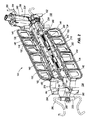
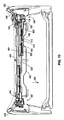
[0008]腰部支持体システムを含む車両座席の斜視図である。[0008] FIG. 1 is a perspective view of a vehicle seat including a lumbar support system. [0009]図1の腰部支持体システムの斜視図である。[0009] FIG. 2 is a perspective view of the lumbar support system of FIG. [0010]図1の腰部支持体システムの分解図である。[0010] FIG. 2 is an exploded view of the lumbar support system of FIG. [0011]図1の腰部支持体システムの駆動機構組立体の分解図である。[0011] FIG. 2 is an exploded view of the drive mechanism assembly of the lumbar support system of FIG. [0012]引込位置にある腰部支持体システムの図1の4−4線による断面図である。[0012] FIG. 4 is a cross-sectional view of the lumbar support system in the retracted position, taken along line 4-4 of FIG. [0013]伸張位置にある腰部支持体システムの図1の4−4線による断面図である。[0013] FIG. 4 is a cross-sectional view of the lumbar support system in the extended position, taken along line 4-4 of FIG. [0014]別の腰部支持体システムを含む車両座席の斜視図である。[0014] FIG. 5 is a perspective view of a vehicle seat including another lumbar support system. [0015]図6の腰部支持体システムの斜視図である。[0015] FIG. 7 is a perspective view of the lumbar support system of FIG. [0016]図6の腰部支持体システムの腰部支持体機構の分解図である。[0016] FIG. 7 is an exploded view of the lumbar support mechanism of the lumbar support system of FIG. [0017]引込位置にある腰部支持体システムの図6の9−9線による断面図である。[0017] FIG. 9 is a cross-sectional view of the lumbar support system in the retracted position, taken along line 9-9 of FIG. [0018]伸張位置にある腰部支持体システムの図6の9−9線による断面図である。[0018] FIG. 9 is a cross-sectional view of the lumbar support system in the extended position, taken along line 9-9 of FIG. [0019]一方の腰部支持体機構を伸張させ他方の腰部支持体機構を引っ込ませた状態の図6の腰部支持体システムの側面図である。[0019] FIG. 7 is a side view of the lumbar support system of FIG. 6 with one lumbar support mechanism extended and the other lumbar support mechanism retracted. [0020]一方の腰部支持体機構を引っ込ませ他方の腰部支持体機構を伸張させた状態の図6の腰部支持体システムの側面図である。[0020] FIG. 7 is a side view of the lumbar support system of FIG. 6 with one lumbar support mechanism retracted and the other lumbar support mechanism extended. [0021]単一の腰部支持体機構を有する別の腰部支持体システムの斜視図である。[0021] FIG. 6 is a perspective view of another lumbar support system having a single lumbar support mechanism. [0022]別の腰部支持体システムを含む車両座席の部分斜視図である。[0022] FIG. 6 is a partial perspective view of a vehicle seat including another lumbar support system. [0023]図14の腰部支持体システムの斜視図である。[0023] FIG. 15 is a perspective view of the lumbar support system of FIG. [0024]図14の腰部支持体システムの腰部支持体機構の分解図である。[0024] FIG. 15 is an exploded view of the lumbar support mechanism of the lumbar support system of FIG. [0025]図14の腰部支持体システムの部分前面図である。[0025] FIG. 15 is a partial front view of the lumbar support system of FIG. [0026]第1位置にある図14の腰部支持体システムの部分前面図である。[0026] FIG. 15 is a partial front view of the lumbar support system of FIG. 14 in a first position. [0027]第1位置にある図14の腰部支持体システムの部分側面図である。[0027] FIG. 15 is a partial side view of the lumbar support system of FIG. 14 in a first position. [0028]第2位置にある図14の腰部支持体システムの部分前面図である。[0028] FIG. 15 is a partial front view of the lumbar support system of FIG. 14 in a second position. [0029]第2位置にある図14の腰部支持体システムの部分側面図である。[0029] FIG. 15 is a partial side view of the lumbar support system of FIG. 14 in a second position. [0030]車両座席のための別の腰部支持体システムの斜視図である。[0030] FIG. 6 is a perspective view of another lumbar support system for a vehicle seat. [0031]図22の腰部支持体システムの分解図である。[0031] FIG. 23 is an exploded view of the lumbar support system of FIG. [0032]伸張位置にある図22の腰部支持体システムの斜視図である。[0032] FIG. 23 is a perspective view of the lumbar support system of FIG. 22 in an extended position. [0033]引込位置にある図22の腰部支持体システムの側面図である。[0033] FIG. 23 is a side view of the lumbar support system of FIG. 22 in a retracted position. [0034]伸張位置にある図22の腰部支持体システムの側面図である。[0034] FIG. 23 is a side view of the lumbar support system of FIG. 22 in an extended position. [0035]車両座席のための別の腰部支持体システムの斜視図である。[0035] FIG. 12 is a perspective view of another lumbar support system for a vehicle seat. [0036]図27の腰部支持体システムの分解図である。[0036] FIG. 28 is an exploded view of the lumbar support system of FIG. [0037]伸張下降位置にある図27の腰部支持体システムの斜視図である。[0037] FIG. 28 is a perspective view of the lumbar support system of FIG. 27 in an extended lowered position. [0038]引込上昇位置にある図27の腰部支持体システムの斜視図である。[0038] FIG. 28 is a perspective view of the lumbar support system of FIG. 27 in a retracted raised position. [0039]伸張上昇位置にある図27の腰部支持体システムの斜視図である。[0039] FIG. 28 is a perspective view of the lumbar support system of FIG. 27 in an extended raised position. [0040]別の腰部支持体システムの分解図である。[0040] FIG. 6 is an exploded view of another lumbar support system. [0041]図32の腰部支持体システムの後方斜視図である。[0041] FIG. 33 is a rear perspective view of the lumbar support system of FIG. [0042]図32の腰部支持体システムの部分前方斜視図である。[0042] FIG. 33 is a partial front perspective view of the lumbar support system of FIG. [0043]図32の腰部支持体システムの3通りの追加の配置向きのうちの1つの斜視図である。[0043] FIG. 33 is a perspective view of one of three additional orientations of the lumbar support system of FIG. [0043]図32の腰部支持体システムの3通りの追加の配置向きのうちの1つの斜視図である。[0043] FIG. 33 is a perspective view of one of three additional orientations of the lumbar support system of FIG. [0043]図32の腰部支持体システムの3通りの追加の配置向きのうちの1つの斜視図である。[0043] FIG. 33 is a perspective view of one of three additional orientations of the lumbar support system of FIG. [0044]別の腰部支持体システムの後方斜視図である。[0044] FIG. 12 is a rear perspective view of another lumbar support system. [0045]図38の腰部支持体システムの部分前方斜視図である。[0045] FIG. 39 is a partial front perspective view of the lumbar support system of FIG. [0046]図38の腰部支持体システムの3通りの追加の配置向きのうちの1つの斜視図である。[0046] FIG. 39 is a perspective view of one of three additional orientations of the lumbar support system of FIG. [0046]図38の腰部支持体システムの3通りの追加の配置向きのうちの1つの斜視図である。[0046] FIG. 39 is a perspective view of one of three additional orientations of the lumbar support system of FIG. [0046]図38の腰部支持体システムの3通りの追加の配置向きのうちの1つの斜視図である。[0046] FIG. 39 is a perspective view of one of three additional orientations of the lumbar support system of FIG.

[0047]本発明の何れの実施形態を詳細に解説するにしてもその前に理解しておくべきこととして、本発明はその適用が次に続く説明又は添付図面に示されている構成の詳細事項及び構成要素の配置に限定されない。本発明は、他の実施形態の余地があり、様々なやり方で実践又は実施される余地がある。同じく理解しておくべきこととして、ここに使用されている言葉遣い及び用語遣いは、説明を目的としており、制限をかけるものと考えられてはならない。「含んでいる」、「備えている」、又は「有している」及びそれらの変化形のここでの使用は、それ以後に記載されている品目及びそれらの等価物はもとより追加の品目も網羅することを意味する。本明細書及び付随の特許請求の範囲での使用に際し、「上側」、「下側」、「頂部」、「底部」、「前」、「後」、及び他の方向に関する用語は、何れかの特定の配置向きを要件とすることを意図しているわけではなく、むしろ説明のみを目的に使用されている。   [0047] Before describing any embodiment of the present invention in detail, it should be understood that the present invention is not limited to the details of construction shown in the following description or the accompanying drawings. It is not limited to the arrangement of items and components. The invention has room for other embodiments and room for practice or implementation in various ways. It should also be understood that the wording and terminology used herein is for illustrative purposes and should not be considered limiting. The use of “including”, “comprising” or “having” and variations thereof herein is not limited to the items listed thereafter and their equivalents as well as additional items. It means to cover. As used herein and in the appended claims, the terms “upper”, “lower”, “top”, “bottom”, “front”, “rear”, and other directions are any It is not intended to require a specific orientation of this, but rather is used for illustrative purposes only.

[0048]図1は座席10を描いており、当該座席は、次に続く説明の目的上、車両の客室内の何れかの車両座席とすることができるが、座席10は必ずしも車両用途に限定されるわけではない。座席10は、概して、座席底部14(仮想線で図示)と、席乗員の水平方向及び垂直方向それぞれの支持のための座席背もたれ部18と、を含んでいる。座席背もたれ部18は座席フレームに対し枢軸22で折り畳み可能である。重ね置かれたクッション30(仮想線で図示)によって覆われているフレーム26が、背もたれ部18のための構造的完全性を提供し、一対の垂直方向支持部材34、38を含んでいる。腰部支持体システム100が、着座した乗員のための調節可能な腰部支持体を可能にするよう垂直方向支持部材34と38の間に延びていてそれら支持部材へ連結されている。   [0048] FIG. 1 depicts a seat 10, which may be any vehicle seat in a vehicle cabin for purposes of the following description, but the seat 10 is not necessarily limited to vehicle applications. It is not done. The seat 10 generally includes a seat bottom 14 (shown in phantom) and a seat back 18 for supporting the seat occupant in the horizontal and vertical directions, respectively. The seat back portion 18 can be folded around a pivot 22 with respect to the seat frame. A frame 26 covered by an overlying cushion 30 (shown in phantom) provides structural integrity for the backrest 18 and includes a pair of vertical support members 34, 38. A lumbar support system 100 extends between and is coupled to the vertical support members 34 and 38 to allow an adjustable lumbar support for a seated occupant.

[0049]図1に示されている様に、腰部支持体システム100は、垂直方向支持部材34と38の間の中間に配置されている腰部支持体要素又はカゴ110を含んでいる。カゴ110は、席乗員に近接している乗員の腰部領域に対する押圧面として機能する略平坦前面114を呈している。座席背もたれ部18の上と内側及び前面114と席乗員の間には快適性向上のための追加のクッション、パッド、又は他の材料が示されていないが納められている。   [0049] As shown in FIG. 1, the lumbar support system 100 includes a lumbar support element or basket 110 positioned intermediate between the vertical support members 34 and 38. The basket 110 presents a substantially flat front surface 114 that functions as a pressing surface against the lumbar region of the occupant close to the seat occupant. Additional cushions, pads, or other materials for increased comfort are shown, but not shown, on the seat back 18 and between the front 114 and the seat occupant.

[0050]図2及び図3は、腰部支持体システム100を近位端120(駆動機構組立体230に近接)と遠位端124に関して参照しながら描いている。カゴ110の上側部分130と下側部分134は、カゴ110の後面150の縁取材146によって全体的に相互接続されている補剛リブ142によって分離された複数の開口138を含むように形成されている。カゴ110の上側部分130と下側部分134の間の中央部分154は取付面158を含んでいる。取付面158は2つの互いに反対側のガイド162のセットを支持しており、各セットは、中央部分154に沿って側方に延びる上側レール166と下側レール170を備えていて、それらレールはカゴ110の近位端120と遠位端124それぞれに向かって集束してケーブルチャネル180を形成しており、その目的は以下に説明されている。   [0050] FIGS. 2 and 3 depict the lumbar support system 100 with reference to the proximal end 120 (proximal to the drive mechanism assembly 230) and the distal end 124. FIG. The upper portion 130 and the lower portion 134 of the cage 110 are formed to include a plurality of openings 138 separated by stiffening ribs 142 that are generally interconnected by a border 146 on the rear surface 150 of the cage 110. Yes. A central portion 154 between the upper portion 130 and the lower portion 134 of the cage 110 includes a mounting surface 158. The mounting surface 158 supports two sets of opposite guides 162, each set comprising an upper rail 166 and a lower rail 170 that extend laterally along the central portion 154, which rails are Converging toward the proximal end 120 and the distal end 124 of the cage 110, respectively, forms a cable channel 180, the purpose of which is described below.

[0051]一対の取り付けピン184が、剛性スピンドルレール192の取り付け穴188内に受け入れられるように取付面158から後方に突き出ている。スピンドルレール192は、上側タブ196と下側タブ(図示せず)のセットを含み、各タブには中央に口200が設けられている。取付面158に隣接して位置決めされたとき、タブ196は互いに反対側のフック204に係合し、フック204は取り付けピン184と共にスピンドルレール192をカゴ110に整列させ固着する。追加の位置決め及び整列が、上下両側のタブ196の突起208と取付面のスロット212(図1も参照)の協働によって提供される。構造的完全性は、ブロック216とスピンドルレール192の内部面の間の接触によって維持される。   [0051] A pair of mounting pins 184 project rearward from the mounting surface 158 to be received in mounting holes 188 in the rigid spindle rail 192. The spindle rail 192 includes a set of upper tabs 196 and lower tabs (not shown), and each tab has a mouth 200 in the center. When positioned adjacent to the mounting surface 158, the tab 196 engages the hooks 204 opposite to each other, and the hook 204 along with the mounting pins 184 aligns and secures the spindle rail 192 to the cage 110. Additional positioning and alignment is provided by the cooperation of the protrusions 208 on the tabs 196 on the top and bottom sides and the slot 212 on the mounting surface (see also FIG. 1). Structural integrity is maintained by contact between the block 216 and the inner surface of the spindle rail 192.
[0052]図2、図3、及び図3Aを参照して、駆動機構組立体又はアクチュエータ230は、モーター234、ピニオン238付きモーターシャフト、ハウジング242、ウォームギヤ246、キャップ250、及びドライブシャフト254を含んでいる。ハウジング242へ締結具256で固着されているモーター234は、D.C.可逆モーターであるのが望ましいが、用途に適した何れの型式の可逆モーターであってもよいし、更には必要に応じて寸法及びパワーが変えられてもよい。モーターシャフトのピニオン238と作動的に係合しているウォームギヤ246は、ドライブシャフト254へ印加されるパワーの直交方向転換及びモーター234からの出力トルク増加を可能にする。ギヤ246はハウジング242内に収容されており、ハウジング242は更にモーター234を残りの駆動機構組立体構成要素へ連結している。スプラインドライブシャフト254は作動中の共回転及びパワー伝達のためにウォームギヤ246と噛み合う。ハウジング242へ付着されているキャップ250は、ウォームギヤ246及びドライブシャフト254のための追加の保護を提供し、モーター234をスピンドルレール192へ固着する。   [0052] Referring to FIGS. 2, 3, and 3A, the drive mechanism assembly or actuator 230 includes a motor 234, a motor shaft with a pinion 238, a housing 242, a worm gear 246, a cap 250, and a drive shaft 254. It is out. A motor 234 that is secured to the housing 242 with fasteners 256 includes a D.P. C. Although it is desirable to be a reversible motor, it can be any type of reversible motor suitable for the application, and the dimensions and power can be varied as required. A worm gear 246 operatively engaged with the motor shaft pinion 238 allows for orthogonal diversion of power applied to the drive shaft 254 and increased output torque from the motor 234. Gear 246 is housed within housing 242, which further couples motor 234 to the remaining drive mechanism assembly components. Spline drive shaft 254 meshes with worm gear 246 for co-rotation and power transmission during operation. A cap 250 attached to the housing 242 provides additional protection for the worm gear 246 and the drive shaft 254 and secures the motor 234 to the spindle rail 192.

[0053]ドライブシャフト254へは、ねじの切られた部材又はスピンドル260が連結されていてスピンドルレール192のかなりの部分に及んでいる。スピンドル260は近位のねじの切られた端264及び遠位のねじの切られた端268を有している。描かれている様に、近位ねじ部は右手側ねじ部であり、遠位ねじ部は左手側ねじ部であるが、代わりの実施形態では向き手方向が入れ替わることもある。近位のねじの切られた端264は、モーター234が動作するとスピンドル260がドライブシャフト254と一体に回転するように、ドライブシャフト254の端へ回転に関して固着されていて当該端の内に画定されている開口部272内に受け入れられている。スピンドル260のねじの切られた各端264、268の周りには、走行部材又はスライダ即ち近位スライダ280及び遠位スライダ284が配置されている。各スライダ280、284は、スピンドル260との係合のための内ねじの切られた本体と、スピンドルレール192の部分として形成されている互いに反対側の縁300、304と噛み合う互いに反対側の溝290、292、294、296と、を有している。互いに反対側のねじの切られたスピンドル端264、268はスピンドルレール192相手のスライダ280、284の溝/縁インターフェースと一体で、スピンドルの回転に際しスライダ280、284のスピンドル260に沿った互いに反対の並進運動を生じさせる。ドライブシャフト254に隣接して置かれているバンパー308が近位スライダ280のための一方の走行端の限界を提供している。中央に位置付けられているストッパ316に隣接する第2バンパー312が近位スライダ280のための第2の走行限界を確立し可動域を画定している。   [0053] A threaded member or spindle 260 is coupled to the drive shaft 254 and extends a substantial portion of the spindle rail 192. Spindle 260 has a proximal threaded end 264 and a distal threaded end 268. As depicted, the proximal thread is a right hand thread and the distal thread is a left hand thread, although alternate orientations may be interchanged in alternative embodiments. Proximal threaded end 264 is fixed in rotation to and defined within the end of drive shaft 254 such that spindle 260 rotates integrally with drive shaft 254 when motor 234 operates. Is received in the opening 272. Around each threaded end 264, 268 of the spindle 260 is a travel member or slider, a proximal slider 280 and a distal slider 284. Each slider 280, 284 has an internally threaded body for engagement with the spindle 260 and opposite grooves engaged with opposite edges 300, 304 formed as part of the spindle rail 192. 290, 292, 294, 296. Opposite threaded spindle ends 264, 268 are integral with the groove / edge interface of the slider 280, 284 against the spindle rail 192, opposite each other along the spindle 260 of the slider 280, 284 as the spindle rotates. Causes translational motion. A bumper 308 placed adjacent to the drive shaft 254 provides one travel end limit for the proximal slider 280. A second bumper 312 adjacent to the centrally located stopper 316 establishes a second travel limit for the proximal slider 280 and defines a range of motion.

[0054]近位可撓性ケーブル320及び遠位可撓性ケーブル324が近位スライダ280及び遠位スライダ284へそれぞれ連結されている。各ケーブル320、324は、第1端330、第2端334、及びケーブル本体338を含んでいる。第1端330はそれぞれのスライダ280、284との一体運動のために当該スライダの本体内に嵌るコネクタ344を有している。各ケーブル320、324のケーブル本体338は、第1端330から延びていて中間区分350を画定しており、その一部分は実質的に各自のチャネル180内に配置されている。中間区分350は、コイル端金具354へ連結されている(例えばケーブル324)又は代わりにフック金具356へ連結されている(例えばケーブル320)第2端334に終端している。コイル端金具354は、捩じりばねの様なばね362の第1端358に係合するように適合されている。遠位端124と関連付けて示されてはいるが、ばね362は近位及び遠位ケーブル320、324のそれぞれの第2端334の一方と共に作動可能であるか両方の側で作動可能である。ばね362はヒンジ374のフック端370へ付着するように構成されている第2端366を含んでいて、乗員が最初に着座したときと乗員の快適性を強化するための作動中の両方について腰部支持体システム100の限定された撓み量を許容する。ケーブル320のフック金具356は互いに反対側のヒンジ374のフック端370の一部分に巻き付いている。   [0054] Proximal flexible cable 320 and distal flexible cable 324 are coupled to proximal slider 280 and distal slider 284, respectively. Each cable 320, 324 includes a first end 330, a second end 334, and a cable body 338. The first end 330 has a connector 344 that fits within the body of the slider for integral movement with the respective slider 280, 284. The cable body 338 of each cable 320, 324 extends from the first end 330 and defines an intermediate section 350, a portion of which is substantially disposed within the respective channel 180. Intermediate section 350 terminates at a second end 334 that is coupled to coil end fitting 354 (eg, cable 324) or alternatively is connected to hook fitting 356 (eg, cable 320). The coil end fitting 354 is adapted to engage a first end 358 of a spring 362, such as a torsion spring. Although shown in conjunction with the distal end 124, the spring 362 can be actuated with one of the second ends 334 of each of the proximal and distal cables 320, 324 or on both sides. The spring 362 includes a second end 366 that is configured to attach to the hook end 370 of the hinge 374 so that the lumbar can be seen both when the occupant first sits and during operation to enhance occupant comfort. A limited amount of deflection of the support system 100 is allowed. The hook 320 of the cable 320 is wound around a part of the hook end 370 of the hinge 374 opposite to each other.

[0055]ヒンジ374はフック端370の反対側でカゴ110の上側部分130及び下側部分134の両方に接合する「リビング」ヒンジとして形成されている。描かれている様に、ヒンジ374は、第1、第2、及び第3の枢動点380、384、388を含んでいるが、3つより少ない又は多い枢動点も本範囲内である。図2、図4、及び図5に示されている様に、枢動点380、384、388は、カゴ110の進行の最中にモーター234との干渉を排除するように配置されている。ヒンジ374及びカゴ110は、単一片として形成されているのが望ましい。代わりに、ヒンジ374は当業者に既知の方式でカゴ110へ固着された別体部片であってもよい。ヒンジ374のフック端370は、フレーム26のそれぞれの垂直方向支持部材34、38(図1参照)へ固定されている取り付けワイヤ390の形態をしている連結要素に上から嵌まるように形成されている。   [0055] The hinge 374 is formed as a “living” hinge that joins both the upper portion 130 and the lower portion 134 of the cage 110 opposite the hook end 370. As depicted, hinge 374 includes first, second, and third pivot points 380, 384, 388, although fewer or more than three pivot points are within the scope. . As shown in FIGS. 2, 4, and 5, the pivot points 380, 384, 388 are arranged to eliminate interference with the motor 234 during the travel of the cage 110. The hinge 374 and the basket 110 are preferably formed as a single piece. Alternatively, the hinge 374 may be a separate piece secured to the cage 110 in a manner known to those skilled in the art. The hook end 370 of the hinge 374 is formed to fit from above onto a connecting element in the form of a mounting wire 390 that is secured to the respective vertical support members 34, 38 (see FIG. 1) of the frame 26. ing.

[0056]作動において、席乗員は、座席背もたれ部18又は座席底部14に隣接して置かれているのが望ましいとされる電気式操作スイッチを使用してパワーアクチュエータ230を起動させる。図4及び図5を参照して、腰部支持体システムは、アクチュエータ230を始動させたとき、完全引込位置(図4)と完全伸張位置(図5)の間の何れかの位置に入れることができる。モーター234がエネルギー供給されるや、ウォームギヤ246の係合がドライブシャフト254を回転させ、同時発生的にスピンドル260を回す。腰部支持体システム100がカゴ110を引っ込めるように起動されるなら、スピンドル260は第1方向に回転する。腰部支持体システム100がカゴ110を伸張させるように起動されるなら、スピンドル260は反対の第2方向に回転する。何れの方向へ起動させるかは使用者が電気式操作スイッチで選択できる。スライダ280、284の溝290、292、294、296とスピンドルレール192の縁300、304との相互作用に因り、スピンドル260の回転はスライダ280、284を並進させ、一方のスライダを近位方向(120)に走行させ、他方のスライダを遠位方向(124)に走行させる。   [0056] In operation, the seat occupant activates the power actuator 230 using an electrically operated switch that is preferably located adjacent to the seat back 18 or seat bottom 14. With reference to FIGS. 4 and 5, the lumbar support system can be placed in any position between the fully retracted position (FIG. 4) and the fully extended position (FIG. 5) when the actuator 230 is activated. it can. As the motor 234 is energized, the engagement of the worm gear 246 rotates the drive shaft 254 and simultaneously rotates the spindle 260. If the lumbar support system 100 is activated to retract the cage 110, the spindle 260 rotates in the first direction. If the lumbar support system 100 is activated to extend the cage 110, the spindle 260 rotates in the opposite second direction. The user can select which direction to start with an electric operation switch. Due to the interaction between the grooves 290, 292, 294, 296 of the sliders 280, 284 and the edges 300, 304 of the spindle rail 192, rotation of the spindle 260 translates the sliders 280, 284 and moves one slider proximally ( 120) and the other slider in the distal direction (124).

[0057]乗員がより多い腰部支持を提供させるようにカゴ110の伸張を所望するなら、スピンドル260の(遠位方向124から視て)時計回りの回転が近位スライダ280をスピンドル260に沿って遠位方向に走行させ遠位スライダ284を近位方向に走行させ、即ちスライダ280とスライダ284を各自の付着されているケーブル320、324共々互いに近寄らせる。スライダ280とスライダ284が集束してゆくと、各ケーブルの中間区間350の部分が各自のチャネル180内で滑動し、カゴ110に接触する。この接触はカゴ110に対し図4に矢印392で示されている様にカゴを上向きに方向付ける力をもたらす。近位スライダ280がバンパー312に接触すると、モーター234は停止し、スピンドル260の回転は止む。或る特定の走行点にてモーター234のエネルギー供給を断つ方法で当業者によく知られている他の方法を腰部支持体システム100と共に使用することも実施可能である。   [0057] If the cage 110 wishes to extend the cage 110 to provide more lumbar support, clockwise rotation of the spindle 260 (as viewed from the distal direction 124) causes the proximal slider 280 to move along the spindle 260. Run in the distal direction and move the distal slider 284 in the proximal direction, ie, move the slider 280 and slider 284 closer together with their attached cables 320, 324. As slider 280 and slider 284 converge, the middle section 350 of each cable slides within its own channel 180 and contacts the basket 110. This contact provides a force on the car 110 that directs the car upward as shown by arrow 392 in FIG. When the proximal slider 280 contacts the bumper 312, the motor 234 stops and the spindle 260 stops rotating. It is possible to use other methods with the lumbar support system 100 that are well known to those skilled in the art in a manner that cuts off the energy supply of the motor 234 at certain travel points.

[0058]取付ワイヤ390へフック端370を定着されているヒンジ374は、撓むことによってカゴ110の運動を円滑化して走行範囲全体に亘る滑らかな動きを提供する。図5に示されている様に、枢動点380、384、388は、完全伸張時のヒンジ374のモーター234周りの折り畳みを可能にする。フレーム26のそれぞれの垂直方向支持体30、34へ各々固着されている取付ワイヤ390は必要に応じ腰部支持体システム100の運動と共に回転する。   [0058] The hinge 374 anchored to the hook wire 390 to the attachment wire 390 facilitates movement of the cage 110 by flexing to provide smooth movement over the entire travel range. As shown in FIG. 5, pivot points 380, 384, 388 allow folding of hinge 374 about motor 234 when fully extended. The attachment wires 390, each affixed to the respective vertical supports 30, 34 of the frame 26, rotate as the lumbar support system 100 moves as needed.

[0059]乗員が腰部支持量を少なくするようにカゴ110の引込を所望するなら、スピンドル260の反時計回りの回転が近位スライダ280をスピンドル260に沿って近位方向に走行させ遠位スライダ284を遠位方向に走行させ、即ちスライダ280とスライダ284を各自の付着されているケーブル320、324共々離れさせる。スライダ280とスライダ284が更に離間されてゆくと、ケーブルの中間区分350からのカゴ110に対する押圧は小さくなりカゴ110は呼応して図5に矢印394で示されている様に後方へ引っ込む。先に説明されている様に、スライダ280がバンパー308に接触するとモーター234は停止する。   [0059] If the occupant wishes to retract the basket 110 to reduce lumbar support, counterclockwise rotation of the spindle 260 causes the proximal slider 280 to travel proximally along the spindle 260 and the distal slider. 284 is moved distally, i.e., the sliders 280 and 284 are moved apart from their attached cables 320 and 324 together. As the slider 280 and slider 284 are further separated, the pressure on the car 110 from the cable middle section 350 decreases and the car 110 responds and retracts backward as indicated by arrow 394 in FIG. As described above, when the slider 280 contacts the bumper 308, the motor 234 stops.

[0060]カゴ110の進行の最中、ケーブル320、324は引込から伸張しそして戻るまで実質的に同じ平面内に配置されたままであり、各ケーブル320、324の第1端330と第2端334の間の角度α(図4参照)は鈍角のままである。   [0060] During the travel of the cage 110, the cables 320, 324 remain in substantially the same plane until they extend from the retract and return, and the first end 330 and the second end of each cable 320, 324 The angle α between 334 (see FIG. 4) remains obtuse.

[0061]図6は、座席410のための腰部支持体システム400の代わりの型を描いており、その全体としての特徴は先に説明されている。座席410は、座席底部414(仮想線で図示)、折り畳み式座席背もたれ部418、及び垂直方向支持部材434、438を有するフレーム426を含んでいる。輪郭マット(contour mat)又はフレックスマット440の形態をしている腰部支持体要素が、側方外側ワイヤ444、中央ワイヤ448、及び側方外側ワイヤ444間に延びる複数の横断ワイヤ452を含んでいる。フレーム426は、更に、ヘッドレスト(図示せず)の支持部を受け入れるための一対の受口456を含んでいる。描かれている様に、腰部支持体システム400は、一対の独立に調節可能な腰部支持体機構500、502を含んでいる。   [0061] FIG. 6 depicts an alternative form of the lumbar support system 400 for the seat 410, the overall features of which have been described previously. The seat 410 includes a frame 426 having a seat bottom 414 (shown in phantom), a folding seat back 418, and vertical support members 434, 438. A lumbar support element in the form of a contour mat or flex mat 440 includes a lateral outer wire 444, a central wire 448, and a plurality of transverse wires 452 extending between the lateral outer wires 444. . The frame 426 further includes a pair of receiving ports 456 for receiving a support portion of a headrest (not shown). As depicted, the lumbar support system 400 includes a pair of independently adjustable lumbar support mechanisms 500, 502.

[0062]図7は腰部支持体システム400を描き、図8が近位の調節可能な腰部支持体機構500の構成要素を近位端520及び遠位端524に関して参照しながら詳しく示している。   [0062] FIG. 7 depicts a lumbar support system 400, with FIG. 8 detailing the components of the proximal adjustable lumbar support mechanism 500 with reference to the proximal end 520 and the distal end 524.

[0063]駆動機構組立体又はアクチュエータ530は、実質的に図3Aに示されている通りであり、先に図1のシステムに関して説明されている様に相互作用するモーター534、ピニオン538付きモーターシャフト、ハウジング542、ウォームギヤ546、キャップ550、及びドライブシャフト554を含んでいる。ねじの切られた部材又はスピンドル560が、ドライブシャフト554へ連結されていてスピンドルレール562のかなりの部分に及んでいる。スピンドル560は右手側近位ねじ部及び左手側遠位ねじ部を有している。近位のねじの切られた端564は、ドライブシャフト554の端へ固着され当該端によって画定されている開口部572内に受け入れられていて、モーター534が動作するやドライブシャフト554と一体に回転する。スピンドル560のねじの切られた各端564、568の周りには、スライダ即ち近位スライダ580及び遠位スライダ584が配置されており、各スライダ580、584は、スピンドル560との係合のための内ねじの切られた本体を有している。互いに反対側の溝590、592、594、596が、スピンドルレール562の部分として形成されている互いに反対側の縁600、604と噛み合って、作動中のスライダ580、584の互いに反対の並進運動を生じさせる。ドライブシャフト554に隣接して置かれているバンパー608が近位スライダ580のための第1の走行限界を提供し、中央に位置付けられているストッパ616に隣接する第2バンパー612が第2の走行限界を提供しており、それら限界が近位スライダ580の可動域を画定している。   [0063] The drive mechanism assembly or actuator 530 is substantially as shown in FIG. 3A, and interacts with the motor shaft 534, pinion 538 motor shaft as previously described with respect to the system of FIG. , Housing 542, worm gear 546, cap 550, and drive shaft 554. A threaded member or spindle 560 is connected to the drive shaft 554 and extends a substantial portion of the spindle rail 562. Spindle 560 has a right hand proximal thread and a left hand distal thread. The proximal threaded end 564 is secured to the end of the drive shaft 554 and is received in an opening 572 defined by the end so that it rotates with the drive shaft 554 as the motor 534 operates. To do. A slider or proximal slider 580 and a distal slider 584 are disposed about each threaded end 564 568 of the spindle 560, and each slider 580, 584 is for engagement with the spindle 560. Having an internally threaded body. Opposite grooves 590, 592, 594, 596 mesh with opposite edges 600, 604 formed as part of the spindle rail 562, to provide opposite translational movement of the active sliders 580, 584. Cause it to occur. A bumper 608 positioned adjacent to the drive shaft 554 provides a first travel limit for the proximal slider 580, and a second bumper 612 adjacent to the centrally located stopper 616 is the second travel. Limits are provided, and these limits define the range of motion of the proximal slider 580.

[0064]近位ケーブル620及び遠位ケーブル624が近位スライダ580及び遠位スライダ584へそれぞれ連結されている。各ケーブル620、624は、第1端630、第2端634、及びケーブル本体638を含んでいる。各ケーブル620、624の第1端630はそれぞれのスライダ580、584との一体運動のために当該スライダの本体へ連結するコネクタ644を含んでいる。各ケーブル620、624のケーブル本体は、第1端630から延びていて中間区分650を画定している。近位腰部支持体機構500の遠位ケーブル624の中間区分650は、図8に描かれている様に、同じ腰部支持体機構の近位ケーブル620の中間区分650より長い。ケーブル624のこの長めの中間区分650は、ケーブル624の内部自由運動を許容するようにケーブル624の直径より広い内径を有している剛性スリーブ652内に納められている。近位及び遠位のケーブル620、624の中間区分650の部分は各々がクリップ660を通り抜けてクリップ660によって収容されており、当該クリップ660が近位及び遠位のケーブル620、624を、そしてそれにより腰部支持体機構500を、フレックスマット440へ外側ワイヤ444を通じて連結している。各中間区分650はフック金具668へ連結されている第2端634に終端し、フック金具668自体はフレーム426のそれぞれの垂直方向支持部材434、436へ固着されている。図7を参照して、遠位腰部支持体機構502は近位腰部支持体機構500の鏡像である。   [0064] Proximal cable 620 and distal cable 624 are coupled to proximal slider 580 and distal slider 584, respectively. Each cable 620, 624 includes a first end 630, a second end 634, and a cable body 638. The first end 630 of each cable 620, 624 includes a connector 644 that couples to the body of the slider for integral movement with the respective slider 580, 584. The cable body of each cable 620, 624 extends from the first end 630 and defines an intermediate section 650. The middle section 650 of the distal cable 624 of the proximal lumbar support mechanism 500 is longer than the middle section 650 of the proximal cable 620 of the same lumbar support mechanism, as depicted in FIG. This long intermediate section 650 of cable 624 is housed in a rigid sleeve 652 having an inner diameter that is wider than the diameter of cable 624 to allow internal free movement of cable 624. The portions of the intermediate section 650 of the proximal and distal cables 620, 624 each pass through the clip 660 and are received by the clip 660, which clip 660, and the proximal and distal cables 620, 624, and so on. Thus, the lumbar support mechanism 500 is connected to the flex mat 440 through the outer wire 444. Each intermediate section 650 terminates at a second end 634 that is connected to a hook fitting 668, which is secured to a respective vertical support member 434 436 of the frame 426. Referring to FIG. 7, distal lumbar support mechanism 502 is a mirror image of proximal lumbar support mechanism 500.

[0065]席乗員は近位腰部支持体機構500又は遠位腰部支持体機構502を同一方式で起動させることを随意に選択することができる。代わりに、席乗員は近位機構500と遠位機構520の両方を同じスイッチで起動させることができるようになっていてもよい。次に続く作動に関する説明は支持体機構500に焦点を当てているが、支持体機構502にも等しく当て嵌まる。   [0065] The seat occupant may optionally choose to activate the proximal lumbar support mechanism 500 or the distal lumbar support mechanism 502 in the same manner. Alternatively, the seat occupant may be able to activate both the proximal mechanism 500 and the distal mechanism 520 with the same switch. The following description of operation focuses on the support mechanism 500, but applies equally to the support mechanism 502.

[0066]席乗員は、座席背もたれ部418又は座席底部414に隣接して置かれているのが望ましいとされる電気式操作スイッチを使用して近位腰部支持体機構500用のアクチュエータ530を起動させる。図9及び図10を参照して、アクチュエータ530を始動させたとき、機構500は、完全引込位置(図9)と完全伸張位置(図10)の間の何れかの位置に入れることができる。モーター534がエネルギー供給されるや、ウォームギヤ546の係合がドライブシャフト554を回転させ、同時発生的にスピンドル560を回す。腰部支持体機構500が、引っ込むように即ちより少ない支持を提供するように起動されるなら、スピンドル560は第1方向に回転する。腰部支持体機構500が、伸張するように即ちより多い支持を提供するように起動されるなら、スピンドル560は反対方向に回転する。何れの方向へ起動させるかは使用者が電気式操作スイッチで選択できる。図1の実施形態同様、スピンドル560の回転がスライダ580、584を並進させ、それらの溝590、592、594、596がスピンドルレール562の縁600、604と相互作用し、その結果、一方のスライダ580、584が近位方向(520)に走行し、他方のスライダ580、584が遠位方向(524)に走行する。   [0066] The seat occupant activates the actuator 530 for the proximal lumbar support mechanism 500 using an electrically operated switch that is preferably located adjacent to the seat back 418 or the seat bottom 414. Let Referring to FIGS. 9 and 10, when the actuator 530 is activated, the mechanism 500 can be placed in any position between the fully retracted position (FIG. 9) and the fully extended position (FIG. 10). When the motor 534 is energized, the engagement of the worm gear 546 rotates the drive shaft 554 and simultaneously rotates the spindle 560. If the lumbar support mechanism 500 is activated to retract, ie provide less support, the spindle 560 rotates in the first direction. If the lumbar support mechanism 500 is activated to extend, i.e., provide more support, the spindle 560 rotates in the opposite direction. The user can select which direction to start with an electric operation switch. As in the embodiment of FIG. 1, rotation of the spindle 560 translates the sliders 580, 584 and their grooves 590, 592, 594, 596 interact with the edges 600, 604 of the spindle rail 562, resulting in one slider. 580, 584 travels in the proximal direction (520) and the other slider 580, 584 travels in the distal direction (524).

[0067]腰部支持体機構500を伸張させるには、席乗員はスピンドル560を(遠位方向524から視て)時計回りに回転させるように機構を起動させて、近位スライダ580をスピンドル560に沿って遠位方向に走行させ遠位スライダ584を近位方向に走行させ、即ちスライダ580とスライダ584を各自の付着されているケーブル620、624共々互いに近寄らせる。スライダ580とスライダ584が集束してゆくと、中間区間650が側方外側ワイヤ444に接触し、機構500が及んでいるフレックスマット440の領域を図9の矢印692で示される様に前方へ押し進める。近位スライダ580がバンパー612に接触すると、モーター534は停止し、スピンドル560の回転は止む。図9及び図10に示されている様に、フック端668は、腰部支持体機構500が前方へ進行する際の当該機構の滑らかな運動を許容するために垂直方向支持部材434、438周りの連結回転を可能にさせる。図示されていないが、ケーブル620、624の一方又は両方と直列に連結されているばねが、限定された撓み量を許容し、装置の快適性を強化するように乗員への「屈従性」を提供することができる。   [0067] To extend the lumbar support mechanism 500, the seat occupant activates the mechanism to rotate the spindle 560 clockwise (as viewed from the distal direction 524), causing the proximal slider 580 to move to the spindle 560. And the distal slider 584 is moved proximally, i.e., the slider 580 and the slider 584 are brought closer together with their attached cables 620, 624. As slider 580 and slider 584 converge, intermediate section 650 contacts side outer wire 444 and pushes the area of flex mat 440 covered by mechanism 500 forward as indicated by arrow 692 in FIG. . When the proximal slider 580 contacts the bumper 612, the motor 534 stops and the spindle 560 stops rotating. As shown in FIGS. 9 and 10, the hook end 668 is provided around the vertical support members 434, 438 to allow smooth movement of the lumbar support mechanism 500 as it advances forward. Allow coupled rotation. Although not shown, a spring coupled in series with one or both of the cables 620, 624 allows a limited amount of deflection and provides "flexibility" to the occupant to enhance the comfort of the device. Can be provided.

[0068]腰部支持量を少なくするよう腰部支持体機構500を引っ込ませるには、席乗員はスピンドル560を反時計回りに回転させるように機構500を起動させて、近位スライダ580を近位方向に走行させ遠位スライダ584を遠位方向に走行させ、即ちスライダ580とスライダ584を各自の付着されているケーブル620、624共々離れさせる。スライダ580とスライダ584に更に隔たりができてゆくと、ケーブル620、624の中間区分650からの側方外側ワイヤ444に対する押圧は小さくなりフレックスマット440は呼応して図10に矢印694で示されている様に後方へ引っ込む。先に説明されている様に、近位スライダ580がバンパー608に接触するとモーター534は停止する。   [0068] To retract the lumbar support mechanism 500 to reduce lumbar support, the seat occupant activates the mechanism 500 to rotate the spindle 560 counterclockwise and causes the proximal slider 580 to move in the proximal direction. The distal slider 584 is moved in the distal direction, that is, the slider 580 and the slider 584 are separated from each other with the cables 620 and 624 attached thereto. As the slider 580 and slider 584 are further separated, the pressure on the lateral outer wire 444 from the intermediate section 650 of the cables 620, 624 is reduced and the flex mat 440 is correspondingly indicated by arrow 694 in FIG. Retract backwards as if As previously described, the motor 534 stops when the proximal slider 580 contacts the bumper 608.

[0069]腰部支持体機構500、502は、独立作動であり、どちらも自身の可動域一杯の範囲に亘って作動させることができる。例えば、両腰部支持体機構500、502は、両方を伸張させることも、両方を引っ込ませることもできるし、又は一方を完全又は部分的に引っ込ませ他方を完全又は部分的に伸張させることもできる。図11を参照して、近位腰部支持体機構500は完全伸張位置にあり、その一方、遠位腰部支持体機構502は完全引込位置にある(視やすくするため機構502のモーターを欠いている)。図12に示されている様に、近位腰部支持体機構500は完全引込位置にあり、その一方、遠位腰部支持体機構502は完全伸張位置にある。図11と図12に描かれている範囲の間で機構500、502の任意の独立伸張度/引込度が実施可能である。機構500と機構502を離隔している垂直方向距離Dは大凡50mmであるが、特定の用途についてより大きい又はより小さい規模とすることができる。 [0069] The lumbar support mechanisms 500, 502 are independent and both can be operated over their full range of motion. For example, both lumbar support mechanisms 500, 502 can be both extended, both retracted, or one fully or partially retracted and the other fully or partially extended. . Referring to FIG. 11, the proximal lumbar support mechanism 500 is in a fully extended position, while the distal lumbar support mechanism 502 is in a fully retracted position (the mechanism 502 lacks a motor for clarity). ). As shown in FIG. 12, the proximal lumbar support mechanism 500 is in a fully retracted position, while the distal lumbar support mechanism 502 is in a fully extended position. Any independent degree of stretch / retraction of the mechanisms 500, 502 can be implemented between the ranges depicted in FIGS. The vertical distance D 1 separating mechanism 500 and mechanism 502 is approximately 50 mm, but can be larger or smaller for a particular application.

[0070]腰部支持体システム100同様に、輪郭マット440の進行の最中、ケーブル620、624は引込から伸張しそして戻るまで実質的に同じ平面内に配置されたままであり、各ケーブル620、624の第1端630と第2端634の間の角度β(図9参照)は鈍角のままである。   [0070] As with the lumbar support system 100, during the course of the contour mat 440, the cables 620, 624 remain in substantially the same plane until they are retracted and retracted, and each cable 620, 624 is located. The angle β (see FIG. 9) between the first end 630 and the second end 634 remains obtuse.

[0071]図13に示されている様に、一部の用途では単一の腰部支持体機構例えば機構500が実質的に先に説明されている通りの機構の作動で以て単独使用されることもある。
[0072]図14は、座席のための腰部支持体システム700の代わりの型を示しており、その全体としての特徴は先に説明されている。座席は垂直方向支持部材734、738を有するフレーム726を含んでいる。輪郭マット又はフレックスマット740の形態をしている腰部支持体要素が、側方外側ワイヤ744、中央ワイヤ748、及び側方外側ワイヤ744間に延びる複数の横断ワイヤ752を含んでいる。腰部支持体システム700は独立に調節可能な腰部支持体機構800を含んでいる。
[0071] As shown in FIG. 13, in some applications, a single lumbar support mechanism, such as mechanism 500, is used alone with the operation of the mechanism substantially as previously described. Sometimes.
[0072] FIG. 14 shows an alternative form of a lumbar support system 700 for a seat, the overall features of which have been described previously. The seat includes a frame 726 having vertical support members 734, 738. A lumbar support element in the form of a contour mat or flex mat 740 includes a lateral outer wire 744, a central wire 748, and a plurality of transverse wires 752 extending between the lateral outer wires 744. The lumbar support system 700 includes an independently adjustable lumbar support mechanism 800.

[0073]図15は腰部支持体システム700を描き、図16が調節可能な腰部支持体機構800の構成要素を近位端820及び遠位端824に関して参照しながら詳しく示している。   [0073] FIG. 15 depicts a lumbar support system 700, with FIG. 16 detailing the adjustable lumbar support mechanism 800 components with reference to the proximal end 820 and the distal end 824.

[0074]駆動機構組立体又はアクチュエータ830は、実質的に図3Aに示されている通りであり、先に図1のシステムに関して説明されている様に相互作用するモーター834、ピニオン838付きモーターシャフト、ハウジング842、ウォームギヤ846、キャップ850、及びドライブシャフト854を含んでいる。ねじの切られた部材又はスピンドル860が、ドライブシャフト854へ連結されていて、スピンドルレール862のかなりの部分に及んでいる。スピンドル860は右手側近位ねじ部及び左手側遠位ねじ部を有している。近位のねじの切られた端864は、ドライブシャフト854の端へ固着され当該端によって画定されている開口部872内に受け入れられていて、モーター834が動作するやドライブシャフト854と一体に回転する。スピンドル860のねじの切られた各端864、868の周りには、スライダ即ち近位スライダ880及び遠位スライダ884が配置されていて、各スライダ580、584は、スピンドル860との係合のための内ねじの切られた本体を有している。互いに反対側の溝890、892、894、896が、スピンドルレール862の部分として形成されている互いに反対側の縁900、904と噛み合って、作動中のスライダ880、884の互いに反対の並進運動を生じさせる。ドライブシャフト854に隣接して置かれているバンパー908が近位スライダ880のための第1の走行限界を提供し、中央に位置付けられているストッパ916に隣接するバンパー912が第2の走行限界を提供しており、それら限界が近位スライダ880の可動域を画定している。   [0074] The drive mechanism assembly or actuator 830 is substantially as shown in FIG. 3A, and interacts with the motor 834, motor shaft with pinion 838 as previously described with respect to the system of FIG. , Housing 842, worm gear 846, cap 850, and drive shaft 854. A threaded member or spindle 860 is connected to the drive shaft 854 and extends over a substantial portion of the spindle rail 862. Spindle 860 has a right hand proximal thread and a left hand distal thread. The proximal threaded end 864 is secured to the end of the drive shaft 854 and is received in an opening 872 defined by the end so that the motor 834 operates and rotates together with the drive shaft 854. To do. A slider or proximal slider 880 and a distal slider 884 are disposed around each threaded end 864, 868 of the spindle 860, and each slider 580, 584 is for engagement with the spindle 860. Having an internally threaded body. Opposite grooves 890, 892, 894, 896 mesh with opposite edges 900, 904 formed as part of the spindle rail 862, to provide opposite translational movement of the active sliders 880, 884. Cause it to occur. A bumper 908 placed adjacent to the drive shaft 854 provides a first travel limit for the proximal slider 880, and a bumper 912 adjacent to the centrally located stopper 916 provides a second travel limit. Provided, and these limits define the range of motion of the proximal slider 880.

[0075]第1ケーブル920が近位スライダ880へ連結され、第2ケーブル924が遠位スライダ884へ連結されている。各ケーブル920、924は、第1終端930、第2終端934、及びケーブル本体938を含んでいる。コネクタ944がそれぞれのスライダ880、884の本体を各自のケーブル本体938へ固着的に連結していて、その結果、コネクタ944とその付着されているケーブル938の間には相対運動が一切存在しない(同じく図14参照)。各ケーブル920、924のケーブル本体938は、第1終端930から第2終端934へ延びていて、それぞれのコネクタ944の一方の側で終わっている第1中間区分950とそれぞれのコネクタ944の他方側で終わっている第2中間区分591へ分割されている(図14参照)。各ケーブル本体938の部分は、各ケーブルの内部自由運動を許容するようにケーブル本体938の直径より広い内径を有している第1及び第2のスリーブ952、954内に作動的に納められている。各ケーブル920、924のケーブル本体938の各終端930、934付近の部分はクリップ960を通り抜けてクリップ960によって収容されており、当該クリップ960が第1及び第2のケーブル920、924を、そしてそれにより腰部支持体機構800を、フレックスマット740へ外側ワイヤ744を通じて連結している。描かれている様に、クリップ960の接手962は、ワイヤがクリップ960へスピンドル860と実質的に平行な方向に進入するような具合に位置付けられているが、クリップ960のうち1つ又はそれ以上のクリップの接手962は、代わりに、ケーブル920、924のためのより直入的経路を許容するようにスピンドル860に向かって角度が付けられていてもよい。第1及び第2の終端930、934は、各々、フック金具968へ連結されており、フック金具968自体はフレーム726のそれぞれの垂直方向支持部材734、738へ固着されている。   [0075] A first cable 920 is coupled to the proximal slider 880 and a second cable 924 is coupled to the distal slider 884. Each cable 920, 924 includes a first end 930, a second end 934, and a cable body 938. Connectors 944 securely connect the bodies of the respective sliders 880, 884 to their respective cable bodies 938 so that there is no relative movement between the connectors 944 and their attached cables 938 ( See also FIG. 14). The cable body 938 of each cable 920, 924 extends from the first end 930 to the second end 934 and terminates on one side of the respective connector 944 and the other side of the respective connector 944. Are divided into second intermediate sections 591 (see FIG. 14). A portion of each cable body 938 is operably contained within first and second sleeves 952, 954 having an inner diameter that is wider than the diameter of cable body 938 to allow internal free movement of each cable. Yes. The portion of each cable 920, 924 near each end 930, 934 of the cable body 938 passes through the clip 960 and is accommodated by the clip 960, which clip 960 connects the first and second cables 920, 924, and so on. Thus, the lumbar support mechanism 800 is connected to the flex mat 740 through the outer wire 744. As depicted, the joint 962 of the clip 960 is positioned such that the wire enters the clip 960 in a direction substantially parallel to the spindle 860, but one or more of the clips 960. The clip joint 962 may instead be angled toward the spindle 860 to allow a more direct path for the cables 920, 924. The first and second terminal ends 930, 934 are each connected to a hook fitting 968, and the hook fitting 968 itself is secured to the respective vertical support members 734, 738 of the frame 726.

[0076]図14及び図16を参照して、スリーブ952のそれぞれは外側端970及び内側端974を含んでいる。スリーブ954の各々は外側端978及び内側端982を含んでいる。各スリーブの外側端970、978は各自のクリップ960へ接続している。スリーブ952の内側端974は、各々、側方金具986の陥凹984に嵌りその中に固着されている。スリーブ954の内側端982は、各々、中央金具990の陥凹988に嵌りその中に固着されている。各金具986、990は、レール862の頂部及び底部のリム994の上に嵌る上側及び下側のチャネル992を含んでいる。   [0076] Referring to FIGS. 14 and 16, each of the sleeves 952 includes an outer end 970 and an inner end 974. Each of the sleeves 954 includes an outer end 978 and an inner end 982. The outer end 970, 978 of each sleeve is connected to its own clip 960. The inner ends 974 of the sleeves 952 are each fitted into and secured to a recess 984 in the side fitting 986. The inner ends 982 of the sleeves 954 are each fitted into and secured to a recess 988 in the central bracket 990. Each bracket 986, 990 includes upper and lower channels 992 that fit over the top and bottom rims 994 of the rail 862.

[0077]席乗員は、座席背もたれ部又は座席底部に隣接して置かれているのが望ましいとされる電気式操作スイッチを使用して腰部支持体機構800用のアクチュエータ830を起動させる。図17−図21を参照して、機構800は、アクチュエータ830を始動させたとき、下側腰部領域よりも上側腰部領域に多くの支持を提供する第1位置(図18−図19)に配置させることもできるし、又は上側腰部領域よりも下側腰部領域に多くの支持を提供する第2位置(図20−図21)に配置させることもできる。   [0077] The seat occupant activates the actuator 830 for the lumbar support mechanism 800 using an electrically operated switch that is preferably located adjacent to the seat back or seat bottom. With reference to FIGS. 17-21, the mechanism 800 is located in a first position (FIGS. 18-19) that provides more support in the upper waist region than in the lower waist region when the actuator 830 is actuated. Or can be placed in a second position (FIGS. 20-21) that provides more support in the lower waist region than in the upper waist region.

[0078]モーター834がエネルギー供給されるや、ウォームギヤ846の係合がドライブシャフト854(図3A参照)を回転させ、同時発生的にスピンドル860を回す。腰部支持体機構800が第1位置へ起動されるなら、スピンドル860は第1方向に回転する。腰部支持体機構800が第2位置へ起動されるなら、スピンドル860は反対方向に回転する。何れの方向へ起動させるかは使用者が電気式操作スイッチで選択できる。先の実施形態同様、スピンドル860の回転がスライダ880、884を並進させ、それらの溝890、892、894、896がスピンドルレール862の縁900、904と相互作用し、その結果、一方のスライダ880、884が近位方向(820)に走行し、他方のスライダ880、884が遠位方向(824)に走行する。   [0078] As the motor 834 is energized, the engagement of the worm gear 846 rotates the drive shaft 854 (see FIG. 3A) and simultaneously rotates the spindle 860. If the lumbar support mechanism 800 is activated to the first position, the spindle 860 rotates in the first direction. If the lumbar support mechanism 800 is activated to the second position, the spindle 860 rotates in the opposite direction. The user can select which direction to start with an electric operation switch. As in the previous embodiment, rotation of the spindle 860 translates the sliders 880, 884, and their grooves 890, 892, 894, 896 interact with the edges 900, 904 of the spindle rail 862, resulting in one slider 880. , 884 travel in the proximal direction (820) and the other slider 880, 884 travels in the distal direction (824).

[0079]図17を参照して、腰部機構800は第1位置と第2位置の間の中間位置にあるところが示されている。腰部支持体機構800を図18及び図19の第1位置へ動かすには、席乗員はスピンドル860を(遠位方向824から視て)時計回りに回転させるように機構を起動させて、近位スライダ880をスピンドル860に沿って遠位方向に走行させ遠位スライダ884を近位方向に走行させ、即ちスライダ880とスライダ884を互いに近寄らせる。スライダ880とスライダ884がそれぞれのコネクタ944共々集束してゆくと、ケーブル920、924の第2中間区分951が、図6以下参照について説明されているのと同様の方式で、それぞれのクリップ960にて側方外側ワイヤ744周りに張られ、上側腰部領域の機構800が及んでいるフレックスマット740の部分を図19に示される様に前方へ押し進める。同時発生的に、ケーブル920、924の第1中間区分950は緩み、結果的に席乗員は下側腰部領域よりも上側腰部領域により大きい支持を体験することになる。近位スライダ880がバンパー912に接触すると、モーター834は停止し、スピンドル860の回転は止む。   [0079] Referring to FIG. 17, the lumbar mechanism 800 is shown in an intermediate position between the first position and the second position. To move the lumbar support mechanism 800 to the first position of FIGS. 18 and 19, the seat occupant activates the mechanism to rotate the spindle 860 clockwise (as viewed from the distal direction 824) and proximally. Slider 880 is moved distally along spindle 860 and distal slider 884 is moved proximally, ie, slider 880 and slider 884 are moved closer together. As the slider 880 and slider 884 converge together with their respective connectors 944, the second intermediate section 951 of the cables 920, 924 attaches to each clip 960 in a manner similar to that described with reference to FIG. The portion of the flex mat 740 stretched around the lateral outer wire 744 and spanned by the upper waist region mechanism 800 is pushed forward as shown in FIG. Concurrently, the first middle section 950 of the cables 920, 924 will loosen, resulting in the seat occupant experiencing greater support in the upper waist region than in the lower waist region. When the proximal slider 880 contacts the bumper 912, the motor 834 stops and the spindle 860 stops rotating.

[0080]腰部支持体機構800を図20及び図21の第2位置へ動かすには、席乗員はスピンドル860を(遠位方向824から視て)反時計回りに回転させるように機構を起動させて、近位スライダ880をスピンドル860に沿って近位方向に走行させ遠位スライダ884を遠位方向に走行させ、即ちスライダ880とスライダ884を離れさせる。スライダ880とスライダ884がそれぞれのコネクタ944共々発散してゆくと、ケーブル920、924の第1中間区分950が、図6以下参照について説明されているのと同様の方式で、それぞれのクリップ960にて側方外側ワイヤ744周りに張られ、下側腰部領域の機構800が及んでいるフレックスマット740の部分を図21に示される様に前方へ押し進める。同時発生的に、ケーブル920、924の第2中間区分951は緩み、結果的に席乗員は上側腰部領域よりも下側腰部領域により大きい支持を体験することになる。近位スライダ880がバンパー908に接触すると、モーター834は停止する。   [0080] To move the lumbar support mechanism 800 to the second position of FIGS. 20 and 21, the occupant activates the mechanism to rotate the spindle 860 counterclockwise (as viewed from the distal direction 824). Thus, the proximal slider 880 is moved in the proximal direction along the spindle 860 and the distal slider 884 is moved in the distal direction, that is, the slider 880 and the slider 884 are separated. As the slider 880 and slider 884 diverge with each connector 944, the first intermediate section 950 of the cables 920, 924 is applied to each clip 960 in a manner similar to that described with reference to FIG. The portion of the flex mat 740 stretched around the lateral outer wire 744 and spanned by the lower lumbar region mechanism 800 is pushed forward as shown in FIG. Concurrently, the second middle section 951 of the cables 920, 924 is loosened, resulting in the seat occupant experiencing greater support in the lower waist region than in the upper waist region. When the proximal slider 880 contacts the bumper 908, the motor 834 stops.

[0081]図19及び図21に描かれている様に上側腰部領域を下側腰部領域から離隔している垂直方向距離Dは、大凡70mmであるが、特定の用途についてより大きい又はより小さい規模とすることができる。一部の構築では、腰部支持体機構800は図19及び図21に描かれている範囲限界でのみ支持を提供するように構成されている。他の構築では、機構800は図19及び図21に描かれている範囲内の何れの位置でも作動し支持を提供することができる。 [0081] vertical distance D 2 which is remote upper waist region from the lower lumbar region as depicted in FIGS. 19 and 21 is a roughly 70 mm, larger or smaller for a particular application It can be a scale. In some constructions, the lumbar support mechanism 800 is configured to provide support only at the range limits depicted in FIGS. In other constructions, the mechanism 800 can operate and provide support in any position within the range depicted in FIGS.

[0082]図22は、車両座席のための別の腰部支持体システム1000を描いており、その全体としての特徴は先に説明されている。システム1000は、座席と一体化できてカゴ1040の形態をしている可撓性腰部支持体要素を取り付けるための垂直方向支持部材1020、1024を有している別体のフレーム部分1010を含んでいる。カゴ1040は、垂直方向支持部材1020、1024に沿ったカゴ1040の一部の走行を円滑化するように頂部縁1048付近に弾性コネクタ1044を含んでいる。描かれている様に、腰部支持体システム1000は調節可能な腰部支持体機構1100を含んでいる。   [0082] FIG. 22 depicts another lumbar support system 1000 for a vehicle seat, the overall features of which have been previously described. The system 1000 includes a separate frame portion 1010 having vertical support members 1020, 1024 for attaching flexible waist support elements that can be integrated with a seat and in the form of a basket 1040. Yes. The basket 1040 includes an elastic connector 1044 near the top edge 1048 to facilitate the travel of a portion of the basket 1040 along the vertical support members 1020, 1024. As depicted, the lumbar support system 1000 includes an adjustable lumbar support mechanism 1100.

[0083]更に図23を参照して、駆動機構組立体又は図3Aに示されているものと同様のアクチュエータ1130が、モーター1134、ハウジング1142、ブラケット1144、及びモータードライブシャフト(図示せず)に直交する即ち座席に関して略垂直方向に向き付けられているねじの切られた部材又はスピンドル1150を回転させるよう作動可能なウォームギヤ配列(図示せず)を含んでいる。スピンドル1150のねじ部の周りには、スピンドル1150との係合のための内部にねじの切られた本体を有する走行部材又はスライダ1160が配置されている。   [0083] Still referring to FIG. 23, a drive mechanism assembly or actuator 1130 similar to that shown in FIG. 3A is provided on the motor 1134, housing 1142, bracket 1144, and motor drive shaft (not shown). It includes a threaded member or a worm gear arrangement (not shown) operable to rotate a threaded member or spindle 1150 that is orthogonal or oriented generally perpendicular to the seat. Around the threaded portion of the spindle 1150, a traveling member or slider 1160 having an internally threaded body for engagement with the spindle 1150 is disposed.

[0084]剛性支持ワイヤ1170が、カゴ1040の下側土台部材1052との係合のための一対のフック1174、1176と、第1及び第2の接続された平行レール1180、1184を有するレール部分と、を含んでいる。支持ワイヤ1170は更にレール1184とフック1176の間にループ1190を形成している。レール1180、1184に適合する寸法の半円溝1204付き端部片1200が、第1面1214から後方に伸びる案内部分1210を含んでいる。案内部分1210は更にスピンドル1150の上側端1220に着座している。支持ワイヤ1170は駆動機構組立体1130へブラケット1144を介して作動的に連結されている。スライダ1160の互いに反対側のチャネル1230が作動中のスライダ1160の並進運動を可能にするよう支持ワイヤ1170のレール1180、1184と噛み合う。ブラケット1144に隣接する第1バンパー1234がスライダ1160のための第1の走行限界を提供し、案内部分1210に隣接する第2バンパー1238が第2の走行限界を提供し、それら限界がスライダ1160の可動域を画定している。   [0084] A rail portion having a rigid support wire 1170 having a pair of hooks 1174, 1176 for engagement with the lower base member 1052 of the cage 1040 and first and second connected parallel rails 1180, 1184. And. Support wire 1170 further forms a loop 1190 between rail 1184 and hook 1176. An end piece 1200 with a semicircular groove 1204 sized to fit the rails 1180, 1184 includes a guide portion 1210 extending rearward from the first surface 1214. Guide portion 1210 is further seated on upper end 1220 of spindle 1150. Support wire 1170 is operatively coupled to drive mechanism assembly 1130 via bracket 1144. Channels 1230 on opposite sides of slider 1160 mesh with rails 1180, 1184 of support wire 1170 to allow translational movement of slider 1160 during operation. A first bumper 1234 adjacent to the bracket 1144 provides a first travel limit for the slider 1160, and a second bumper 1238 adjacent to the guide portion 1210 provides a second travel limit, which limits the slider 1160. A range of motion is defined.

[0085]ケーブル1250が、第1端1254、第2端1258、及びケーブル本体1260を含んでいる。第1端1254は、スライダ1160の本体へそれとの一体運動のために連結しているコネクタ1264と一体に形成されているか又はコネクタ1264へ固着されている。ケーブル本体1260は第1端1254から案内部分1210を通ってカゴ1040の頂部縁1048に向かい、カゴ1040の縁1048付近に横方向の大凡中央に置かれているブレース部材1274によって画定される通路1270を通って延びている。通路1270は弓状ケーブル接触部分1278を備えて形成されているので、ケーブル1250は大凡180°方向転換し下向きに下側土台部材1052の方向に進み、即ち、第1端1254と第2端1258の間の角度が大凡0°になるということであるが、大凡0°から大凡15°までを範囲としてもよい。ケーブル1250の第2端1258はアイレット1282へ固定的に接続されており、アイレット1282はばね1290の第1端1286を通して受け入れ、ばねの第2端1294はばね1290をループ1190へ連結している。   [0085] The cable 1250 includes a first end 1254, a second end 1258, and a cable body 1260. The first end 1254 is integrally formed with or secured to the connector 1264 that is coupled to the body of the slider 1160 for integral movement therewith. The cable body 1260 passes from the first end 1254 through the guide portion 1210 to the top edge 1048 of the cage 1040 and is defined by a passage 1270 defined by a brace member 1274 located approximately centrally laterally near the edge 1048 of the cage 1040. Extending through. Since the passage 1270 is formed with an arcuate cable contact portion 1278, the cable 1250 turns approximately 180 ° and travels downward toward the lower base member 1052, ie, the first end 1254 and the second end 1258. The angle between the two points is approximately 0 °, but the range may be approximately 0 ° to approximately 15 °. The second end 1258 of the cable 1250 is fixedly connected to the eyelet 1282, which receives through the first end 1286 of the spring 1290, and the second end 1294 of the spring couples the spring 1290 to the loop 1190.

[0086]席乗員は、先に他の実施形態について論じられている様に、座席背もたれ部又は座席底部に隣接して置かれているのが望ましいとされる電気式操作スイッチを使用して腰部支持体機構1100用のアクチュエータ1130を起動させる。図22及び図24(更には図25及び図26)を参照して、機構1100は、アクチュエータ1130を始動させたとき、完全引込(図22)と完全伸張(図24)の間の何れかの位置に入れることができる。モーター1134がエネルギー供給されるや、ウォームギヤの係合がドライブシャフトを回転させ、同時発生的にスピンドル1150を回す。腰部支持体機構1100が、引っ込むように即ちより少ない支持を提供するように起動されるなら、スピンドル1150は第1方向に回転する。腰部支持体機構1100が、伸張するように即ちより多い支持を提供するように起動されるなら、スピンドル1150は反対の第2方向に回転する。何れの方向へ起動させるかは使用者が電気式操作スイッチで選択できる。スピンドル1150の回転がスライダ1160を並進させ、それらのチャネル1204がレール1180、1184に沿って並進する。   [0086] The seat occupant uses the electronically operated switch, which is preferably located adjacent to the seat back or bottom of the seat, as previously discussed for other embodiments. The actuator 1130 for the support mechanism 1100 is activated. With reference to FIGS. 22 and 24 (and also FIGS. 25 and 26), the mechanism 1100 can be any of a fully retracted (FIG. 22) and fully extended (FIG. 24) when the actuator 1130 is activated. Can be put into position. When the motor 1134 is energized, the engagement of the worm gear rotates the drive shaft and simultaneously rotates the spindle 1150. If the lumbar support mechanism 1100 is activated to retract, or provide less support, the spindle 1150 rotates in the first direction. If the lumbar support mechanism 1100 is activated to stretch, i.e., provide more support, the spindle 1150 rotates in the opposite second direction. The user can select which direction to start with an electric operation switch. The rotation of the spindle 1150 translates the sliders 1160 and their channels 1204 translate along the rails 1180, 1184.

[0087]腰部支持体機構1100を伸張させるには、席乗員はスピンドル1150を第2方向に回転させるように機構を起動させて、スライダ1160を下向きに土台部材1052に向けて動くように仕向ける。スライダ1160が動いてゆくと、ケーブル本体1260がブレース1274の弓状部分1278に接触する。ケーブル1250の第1端1254と第2端1258の間の張りがケーブル本体1260を通って作用し、ブレース1274へ下向きの力を与える。ブレース1274がカゴ1040の具体的には頂部縁1048付近へ固定的に固着されており、その一方でケーブル1250が同時発生的に土台部材1052へ支持ワイヤ1170を通じて間接的に固着されているため、カゴ1040の頂部縁1048は、弾性コネクタ1044によって促されるようにして、フレーム部分1010の垂直方向支持部材1020、1024を滑り降りてゆき、図24に示されている様に席乗員の腰部領域を支持するようにカゴ1040の腰部接触区域を前方へ伸張させる。スライダ1160がバンパー1234に接触すると、モーター1134は停止し、スピンドル1150の回転は止む。   [0087] To extend the lumbar support mechanism 1100, the seat occupant activates the mechanism to rotate the spindle 1150 in the second direction and directs the slider 1160 to move downward toward the base member 1052. As the slider 1160 moves, the cable body 1260 contacts the arcuate portion 1278 of the brace 1274. The tension between the first end 1254 and the second end 1258 of the cable 1250 acts through the cable body 1260 and provides a downward force on the brace 1274. Because the brace 1274 is fixedly fixed to the cage 1040, specifically near the top edge 1048, while the cable 1250 is simultaneously fixed to the base member 1052 indirectly through the support wire 1170, The top edge 1048 of the basket 1040 slides down the vertical support members 1020, 1024 of the frame portion 1010 as prompted by the elastic connector 1044 to support the seat occupant's waist region as shown in FIG. As such, the waist contact area of the cage 1040 is extended forward. When the slider 1160 contacts the bumper 1234, the motor 1134 stops and the spindle 1150 stops rotating.

[0088]腰部支持量を少なくするように腰部支持体機構1100を引っ込ませるには、席乗員はスピンドル1150を第1方向に回転させるように機構1100を起動させて、スライダ1160を上向きに頂部縁1048に向けて動くように仕向ける。スライダ1160がその様に走行してゆくと、図25及び図26に更に描かれている様に、ケーブル本体1260からの弓状部分1278に対する押圧が小さくなり、カゴ1040は、呼応して後方へ引っ込み、頂部縁1048を垂直方向支持部材1020、1024に沿って上向きに撓ませる。先に説明されている様に、スライダ1160がバンパー1238に接触するとモーター1134は停止する。   [0088] To retract the lumbar support mechanism 1100 to reduce the lumbar support, the seat occupant activates the mechanism 1100 to rotate the spindle 1150 in the first direction and the slider 1160 upwards to the top edge. Turn to move towards 1048. As the slider 1160 travels in that manner, the pressure on the arcuate portion 1278 from the cable body 1260 is reduced, as further depicted in FIGS. 25 and 26, and the car 1040 is correspondingly moved backwards. Retract and flex the top edge 1048 upward along the vertical support members 1020, 1024. As described above, the motor 1134 stops when the slider 1160 contacts the bumper 1238.

[0089]一部の用途では、ブレース1274は、頂部縁1048の少なくとも一部分に及ぶ横部片(図示せず)であって望ましくはばね1290の第2端1294のための連結面を呈する第2の剛性ワイヤの形態をしている横部片に置き換えられている。図22−図26に示され説明されているものより短いケーブル1250を用いると、モーター1134が動作してスピンドル1150を回転させスライダ1160を並進させる際、より短いケーブル1250は、カゴ1040を同じように伸張させたり引っ込ませたりするために、先に説明されている様にケーブル本体1260を通じてブレース1274へ作用するのではなしに、ばね1290(即ち第2端1294)を通じて直接的に力を横部材へそしてひいてはカゴ1040の頂部縁1048へ加えるように作用する。換言すると、ばねフック1294は、支持ワイヤ1170側のループ1190の代わりに横部材へ付着されるということである。代わりに、一部の用途では、作動時、ケーブルの第2端1258は直接に(ばね1290無しに)頂部縁1048へ下向きの力を加える。   [0089] In some applications, the brace 1274 is a transverse piece (not shown) that spans at least a portion of the top edge 1048, and preferably presents a connection surface for the second end 1294 of the spring 1290. It is replaced by a horizontal piece in the form of a rigid wire. Using a shorter cable 1250 than that shown and described in FIGS. 22-26, when the motor 1134 operates to rotate the spindle 1150 and translate the slider 1160, the shorter cable 1250 causes the cage 1040 to move the same way. Rather than acting on the brace 1274 through the cable body 1260 as previously described, the force is applied directly to the cross member through the spring 1290 (ie, the second end 1294) as described above. Then, it acts to add to the top edge 1048 of the cage 1040. In other words, the spring hook 1294 is attached to the cross member instead of the loop 1190 on the support wire 1170 side. Instead, in some applications, the second end 1258 of the cable applies a downward force directly to the top edge 1048 (without the spring 1290) in operation.

[0090]図27は、システム1000と同様の特徴を有する、車両座席のための別の腰部支持体システム1300を描いている。分かり易いように、システム1300には新たに符号が付されている。システム1300は、可撓性腰部支持体カゴ1340を取り付けるための垂直方向支持部材1320、1324を有する別体のフレーム部分1310を含んでいる。カゴ1340は、垂直方向支持部材1320、1324に沿ったカゴ1340の走行を円滑化するように、頂部縁1348付近に弾性コネクタ1344を、下側土台部材1352付近に弾性コネクタ1350、1351を、含んでいる。描かれている様に、腰部支持体システム1300は調節可能な腰部支持体機構1400を含んでいる。   [0090] FIG. 27 depicts another lumbar support system 1300 for a vehicle seat having features similar to the system 1000. For ease of understanding, the system 1300 is newly numbered. System 1300 includes a separate frame portion 1310 having vertical support members 1320, 1324 for attaching a flexible waist support cage 1340. The basket 1340 includes an elastic connector 1344 near the top edge 1348 and an elastic connector 1350, 1351 near the lower base member 1352 so as to facilitate the travel of the basket 1340 along the vertical support members 1320, 1324. It is out. As depicted, the lumbar support system 1300 includes an adjustable lumbar support mechanism 1400.

[0091]更に図28を参照して、一対の駆動機構組立体又は図22−図23に示されているアクチュエータ1130と同様のアクチュエータ1430、1432が、各々、モーター1434、ハウジング1442、ブラケット1444、及びそれぞれのモータードライブシャフト(図示せず)に直交する即ち座席に関して略垂直方向に向き付けられているねじの切られた部材又はスピンドル1450、1452を回転させるよう作動可能なウォームギヤ配列(図示せず)を含んでいる。スピンドル1450のねじ部の周りには、スピンドル1450との係合のための内部にねじの切られた本体を有するスライダ1460が配置されている。スピンドル1452のねじ部の周りには、スピンドル1452との係合のための内部にねじの切られた本体を有するブロック1462が配置されている。   [0091] Still referring to FIG. 28, a pair of drive mechanism assemblies or actuators 1430, 1432 similar to the actuator 1130 shown in FIGS. 22-23, respectively, include a motor 1434, a housing 1442, a bracket 1444, And a worm gear arrangement (not shown) operable to rotate a threaded member or spindle 1450, 1452 orthogonal to each motor drive shaft (not shown) or oriented generally perpendicular to the seat. ) Is included. A slider 1460 having an internally threaded body for engagement with the spindle 1450 is disposed around the threaded portion of the spindle 1450. A block 1462 having an internally threaded body for engagement with the spindle 1452 is disposed around the threaded portion of the spindle 1452.

[0092]剛性支持ワイヤ1470が、下側土台部材1352との係合のための一対のフック1474、1476と、第1及び第2の接続された平行レール1480、1484を有する第1レール部分並びに第1及び第2の接続された平行レール1486、1488を有する第2レール部分と、を含んでいる。レール1180、1184及びレール1186、1188にそれぞれ適合する寸法の半円溝1504付きの第1及び第2の端部片1500が、各々、後方に伸びる案内部分1510を含んでいる。各端部片1500の案内部分1510は更にそれぞれのスピンドル1450、1452の上側端1520、1522に着座している。支持ワイヤ1470は駆動機構組立体1430、1432へブラケット1444を介して作動的に連結されている。   [0092] A rigid support wire 1470 includes a pair of hooks 1474, 1476 for engagement with the lower base member 1352, a first rail portion having first and second connected parallel rails 1480, 1484, and And a second rail portion having first and second connected parallel rails 1486, 1488. First and second end pieces 1500 with semicircular grooves 1504 sized to fit the rails 1180, 1184 and rails 1186, 1188, respectively, each include a guide portion 1510 extending rearward. The guide portion 1510 of each end piece 1500 is further seated on the upper end 1520, 1522 of the respective spindle 1450, 1452. Support wire 1470 is operatively coupled to drive mechanism assemblies 1430, 1432 via bracket 1444.

[0093]スライダ1460の互いに反対側のチャネル1530が作動中のスライダ1460の並進運動を生じさせるよう支持ワイヤ1470のレール1480、1484と噛み合う。ブラケット1444に隣接する第1バンパー1534がスライダ1460のための第1の走行限界を提供し、関連付けられている端部片1500の案内部分1510に隣接する第2バンパー1538が第2の走行限界を提供し、それら限界がスライダ1460の可動域を画定している。   [0093] Channels 1530 on opposite sides of slider 1460 engage with rails 1480, 1484 of support wire 1470 to cause translational movement of slider 1460 in operation. A first bumper 1534 adjacent to the bracket 1444 provides a first travel limit for the slider 1460, and a second bumper 1538 adjacent to the guide portion 1510 of the associated end piece 1500 provides a second travel limit. Provided, and the limits define the range of motion of the slider 1460.

[0094]ブロック1462の互いに反対側のチャネル1540が支持ワイヤ1470のレール1486、1488と噛み合う。ブロック1462は、垂直方向支持部材1320、1324へ連結されそれらの間を延びる横棒1544を受け入れる貫通している開口1542を含んでいる。横棒1544は、支持部材1320、1324へ帯1546で固定されている。従って、ブロック1462もまたフレーム部分1310に対して固定されている。第1バンパー1548及び第2バンパー1549が、更に詳細に説明されている様に、ブロック1462と関連付けられる走行限界を決める。   [0094] Channels 1540 on opposite sides of block 1462 mesh with rails 1486, 1488 of support wire 1470. Block 1462 includes a through opening 1542 that receives a transverse bar 1544 coupled to and extending between vertical support members 1320, 1324. The horizontal bar 1544 is fixed to the support members 1320 and 1324 with a band 1546. Accordingly, the block 1462 is also fixed with respect to the frame portion 1310. First bumper 1548 and second bumper 1549 determine travel limits associated with block 1462 as described in further detail.

[0095]ケーブル1550が、第1端1554、第2端1558、及びケーブル本体1560を含んでいる。第1端1554は、スライダ1460の本体へそれとの一体運動のために連結しているコネクタ1564と一体に形成されているか又はコネクタ1564へ固着されている。ケーブル本体1560は第1端1554から関連付けられている端部片1500の案内部分1510を通ってカゴ1340の頂部縁1348に向かって延びている。ケーブル本体1560は、カゴ1340の縁1348付近に横方向の大凡中央に置かれているブレース部材1574によって画定される通路1570を通っている。通路1570は弓状ケーブル接触部分1578を備えて形成されているので、ケーブル1550は大凡180°方向転換し下向きに下側土台部材1352の方向に進み、即ち、第1端1554と第2端1558の間の角度が大凡0°になるということであるが、大凡0°から大凡15°までを範囲としてもよい。ケーブル1550の第2端1558はフック1582へ固定的に接続されており、フック1582は端部片1500の開口1586を通ってスピンドル1452と接触に受け入れられている。   [0095] A cable 1550 includes a first end 1554, a second end 1558, and a cable body 1560. First end 1554 is integrally formed with or secured to connector 1564 that is coupled to the body of slider 1460 for integral movement therewith. The cable body 1560 extends from the first end 1554 through the guide portion 1510 of the associated end piece 1500 toward the top edge 1348 of the cage 1340. The cable body 1560 passes through a passageway 1570 defined by a brace member 1574 located approximately centrally in the lateral direction near the edge 1348 of the cage 1340. Since the channel 1570 is formed with an arcuate cable contact portion 1578, the cable 1550 turns approximately 180 ° and travels downwardly toward the lower foundation member 1352, ie, the first end 1554 and the second end 1558. The angle between the two points is approximately 0 °, but the range may be approximately 0 ° to approximately 15 °. The second end 1558 of the cable 1550 is fixedly connected to a hook 1582 that is received in contact with the spindle 1452 through the opening 1586 in the end piece 1500.

[0096]席乗員は、先に他の実施形態について論じられている様に、座席背もたれ部又は座席底部に隣接して置かれているのが望ましいとされる電気式操作スイッチを使用して腰部支持体機構1400用のアクチュエータ1430、1432を起動させる。図27及び図29を参照して、機構1400は、アクチュエータ1430を始動させたとき、完全引込(図27)と完全伸張(図29)の間の何れかの位置に入れることができる。アクチュエータ1430のモーター1434がエネルギー供給されるや、ウォームギヤの係合がドライブシャフトを回転させ、同時発生的にスピンドル1450を回す。腰部支持体機構1400が、引っ込むように即ちより少ない支持を提供するように起動されるなら、スピンドル1450は第1方向に回転する。腰部支持体機構1400が、伸張するように即ちより多い支持を提供するように起動されるなら、スピンドル1450は反対の第2方向に回転する。何れの方向へ起動させるかは使用者が電気式操作スイッチで選択できる。スピンドル1450の回転がスライダ1460を並進させ、それらのチャネル1504がレール1480、1484と相互作用する。   [0096] The seat occupant uses the electronic control switch, which is preferably located adjacent to the seat back or bottom of the seat, as discussed above for other embodiments. Actuators 1430 and 1432 for the support mechanism 1400 are activated. Referring to FIGS. 27 and 29, the mechanism 1400 can be placed in any position between full retraction (FIG. 27) and full extension (FIG. 29) when the actuator 1430 is actuated. When the motor 1434 of the actuator 1430 is energized, the engagement of the worm gear rotates the drive shaft and simultaneously rotates the spindle 1450. If the lumbar support mechanism 1400 is activated to retract or provide less support, the spindle 1450 rotates in the first direction. If the lumbar support mechanism 1400 is actuated to stretch, i.e., provide more support, the spindle 1450 rotates in the opposite second direction. The user can select which direction to start with an electric operation switch. The rotation of the spindle 1450 translates the slider 1460 and their channels 1504 interact with the rails 1480, 1484.

[0097]腰部支持体機構1400を伸張させるには、席乗員はスピンドル1450を第2方向に回転させるように機構を起動させて、スライダ1460を下向きに土台部材1352に向けて動くように仕向ける。スライダ1460が動いてゆくと、ケーブル本体1460がブレース1574の弓状部分1578に接触する。ケーブル1550の第1端1554と第2端1558間の張りがケーブル本体1560を通って作用し、ブレース1574へ下向きの力を与える。ブレース1574がカゴ1340の具体的には頂部縁1348付近へ固定的に固着されており、その一方でケーブル1550が同時発生的に土台部材1352へ支持ワイヤ1470を通じて間接的に固着されているため、カゴ1340の頂部縁1348は、弾性コネクタ1344によって促されるようにして、フレーム部分1310の垂直方向支持部材1320、1324を滑り降りてゆき、図29に示されている様に席乗員の腰部領域を支持するようにカゴ1340の腰部接触区域を前方へ伸張させる。スライダ1460がバンパー1534に接触すると、アクチュエータ1430のモーター1434は停止し、スピンドル1450の回転は止む。   [0097] To extend the waist support mechanism 1400, the seat occupant activates the mechanism to rotate the spindle 1450 in the second direction and directs the slider 1460 to move downward toward the base member 1352. As the slider 1460 moves, the cable body 1460 contacts the arcuate portion 1578 of the brace 1574. The tension between the first end 1554 and the second end 1558 of the cable 1550 acts through the cable body 1560 and provides a downward force on the brace 1574. Because the brace 1574 is fixedly secured to the cage 1340, specifically near the top edge 1348, while the cable 1550 is simultaneously secured to the base member 1352 through the support wire 1470, The top edge 1348 of the basket 1340 slides down the vertical support members 1320 and 1324 of the frame portion 1310 as prompted by the elastic connector 1344 to support the seat occupant's waist region as shown in FIG. As such, the waist contact area of the basket 1340 is extended forward. When the slider 1460 contacts the bumper 1534, the motor 1434 of the actuator 1430 stops and the rotation of the spindle 1450 stops.

[0098]腰部支持量を少なくするように腰部支持体機構1400を引っ込ませるには、席乗員はスピンドル1450を第1方向に回転させるように機構1400を起動させて、スライダ1460を上向きに頂部縁1348に向けて動くように仕向ける。スライダ1460がその様に走行してゆくと、ケーブル本体1560からの弓状部分1578に対する押圧が小さくなり、カゴ1340は、呼応して後方へ引っ込み、頂部縁1348を垂直方向支持部材1320、1324に沿って上向きに撓ませる。先に説明されている様に、スライダ1460がバンパー1538に接触するとアクチュエータ1430のモーター1434は停止する。   [0098] To retract the lumbar support mechanism 1400 to reduce the amount of lumbar support, the seat occupant activates the mechanism 1400 to rotate the spindle 1450 in the first direction and causes the slider 1460 to face upward. Move to move toward 1348. As the slider 1460 travels in that manner, the pressure on the arcuate portion 1578 from the cable body 1560 decreases, and the cage 1340 responds and retracts backward, causing the top edge 1348 to move to the vertical support members 1320, 1324. Bend upward along. As described above, when the slider 1460 contacts the bumper 1538, the motor 1434 of the actuator 1430 stops.

[0099]図27及び図30を参照して、支持体機構1400及びカゴ1340は、席乗員がカゴ1340を所望通りに位置決めする融通性を許容するように垂直方向に調節可能である。機構1400は、アクチュエータ1432を始動させたとき、完全下降(図27)と完全上昇(図30)の間の何れかの位置に入れることができる。アクチュエータ1432のモーター1434がエネルギー供給されるや、ウォームギヤの係合がドライブシャフトを回転させ、同時発生的にスピンドル1452を回す。腰部支持体システム1400が下降するように起動されるなら、スピンドル1452は第1方向に回転する。腰部支持体システム1400が上昇するように起動されるなら、スピンドル1452は反対の第2方向に回転する。何れの方向へ起動させるかは使用者が電気式操作スイッチで選択できる。スピンドル1452の回転は機構1400及びカゴ1340を固定ブロック1462に対して並進させ、そのチャネル1540がレール1486、1488と相互作用する。   [0099] Referring to FIGS. 27 and 30, the support mechanism 1400 and the basket 1340 are vertically adjustable to allow the seat occupant the flexibility to position the basket 1340 as desired. The mechanism 1400 can be in any position between fully lowered (FIG. 27) and fully raised (FIG. 30) when the actuator 1432 is activated. When the motor 1434 of the actuator 1432 is energized, the engagement of the worm gear rotates the drive shaft and simultaneously rotates the spindle 1452. If the lumbar support system 1400 is activated to descend, the spindle 1452 rotates in the first direction. If the lumbar support system 1400 is activated to rise, the spindle 1452 rotates in the opposite second direction. The user can select which direction to start with an electric operation switch. The rotation of the spindle 1452 translates the mechanism 1400 and the basket 1340 relative to the fixed block 1462 so that its channel 1540 interacts with the rails 1486, 1488.

[0100]腰部支持体機構1400及び支持体1340を上昇させるには、席乗員はスピンドル1452を第2方向に回転させるように機構を起動させる。スピンドル1452のねじ部とフレーム部分1310へ固定されているブロック1462のねじ部の相互作用が、機構1400及びカゴ1340全体をブロック1462に対して上向きに並進させるように仕向ける。アクチュエータ1430を更に動作させなければ、ケーブル1550内の張りが維持された状態でカゴ1340の伸張度は不変のままである。コネクタ1344、1350、1351は垂直方向支持部材1320、1324に作動的に接触し、カゴ1340の上向運動を許容及び案内してカゴ1340の腰部接触区域を垂直方向に所望通り位置付ける。バンパー1548がブロック1462に接触すると、アクチュエータ1432のモーター1434は停止し、スピンドル1452の回転は止む。腰部支持体機構1400を下降させるには、席乗員はスピンドル1452を第1方向に回転させるように機構1400を起動させ、機構1400及びカゴ1340がブロック1462に対して下向きに並進するよう仕向ける。先に説明されている様に、バンパー1549がブロック1462に接触するとアクチュエータ1432のモーター1434は停止する。   [0100] To raise the waist support mechanism 1400 and the support 1340, the seat occupant activates the mechanism to rotate the spindle 1452 in the second direction. The interaction of the threaded portion of the spindle 1452 and the threaded portion of the block 1462 secured to the frame portion 1310 directs the entire mechanism 1400 and basket 1340 to translate upward relative to the block 1462. If the actuator 1430 is not further operated, the degree of expansion of the cage 1340 remains unchanged while the tension in the cable 1550 is maintained. Connectors 1344, 1350, 1351 operatively contact the vertical support members 1320, 1324 to allow and guide upward movement of the basket 1340 to position the waist contact area of the basket 1340 in the vertical direction as desired. When the bumper 1548 contacts the block 1462, the motor 1434 of the actuator 1432 stops and the rotation of the spindle 1452 stops. To lower the lumbar support mechanism 1400, the seat occupant activates the mechanism 1400 to rotate the spindle 1452 in the first direction and directs the mechanism 1400 and the basket 1340 to translate downward relative to the block 1462. As previously described, when bumper 1549 contacts block 1462, motor 1434 of actuator 1432 stops.

[0101]図30及び図31を参照して、カゴ1340は、バンパー1548、1549によって決まる垂直方向範囲内の何れの高さにても、先に説明されている様にアクチュエータ1430の起動を通じて一杯に引っ込ませたり伸張させたりすることができる。アクチュエータ1430、1432を別々に作動させることは必須ではなく、従って垂直方向の調節及び引込/伸張は同時発生的に達成させることもできる。   [0101] Referring to FIGS. 30 and 31, the basket 1340 is fully loaded through activation of the actuator 1430 at any height within the vertical range determined by the bumpers 1548, 1549, as previously described. Can be retracted or extended. It is not essential that the actuators 1430, 1432 be actuated separately, so that vertical adjustment and retraction / extension can be accomplished simultaneously.

[0102]図32−図34は、腰部支持体システム2100を近位端2120及び遠位端2124に関して参照しながら描いている。カゴ2110の上側部分2130と下側部分2134は、カゴ2110の後面2150の縁取材2146によって全体的に相互接続されている補剛リブ2142によって分離された複数の開口2138を含むように形成されている。カゴ2110の上側部分2130と下側部分2134の間の中央部分2154は取付面2158を含んでいる。取付面2158は、中間案内2162及び互いに反対側のケーブルチャネル2180を支持しており、その目的は以下に説明されている。   [0102] FIGS. 32-34 depict lumbar support system 2100 with reference to proximal end 2120 and distal end 2124. FIG. The upper portion 2130 and the lower portion 2134 of the cage 2110 are formed to include a plurality of openings 2138 separated by stiffening ribs 2142 that are generally interconnected by a border 2146 on the rear surface 2150 of the cage 2110. Yes. A central portion 2154 between the upper portion 2130 and the lower portion 2134 of the cage 2110 includes a mounting surface 2158. Mounting surface 2158 supports intermediate guide 2162 and opposite cable channels 2180, the purpose of which is described below.

[0103]スピンドルレール2192は、取付面2158に略直角に向き付けられている上側タブと下側タブのセット2196を含んでおり、取付面2158は対応する複数のスロット2212を含んでいる。図34に示されている様に、タブ2196及びスロット2212はその様に設えられているので、組み立てられるとタブ2196はスロット2212を抜けて突出したら次いで上方又は下方へ向きを変え又は曲がってスピンドルレール2192をカゴ2110へ永久的に固着する。腰部支持体システム2100は、スピンドルレール2129をカゴ2110へ固着するのに他の締結具、ブラケット、又は他の金物類を一切使用していない。   [0103] The spindle rail 2192 includes a set of upper and lower tabs 2196 oriented substantially perpendicular to the mounting surface 2158, which includes a plurality of corresponding slots 2212. As shown in FIG. 34, the tabs 2196 and slots 2212 are so provided, so that when assembled, the tabs 2196 turn or bend upwards or downwards as they project out of the slots 2212 and turn the spindle. The rail 2192 is permanently fixed to the basket 2110. The lumbar support system 2100 does not use any other fasteners, brackets, or other hardware to secure the spindle rail 2129 to the cage 2110.

[0104]駆動機構組立体又はアクチュエータ2230は、モーター2234、ハウジング2242、及びウォームギヤとドライブシャフトを収容しているキャップ2250、を含んでおり、それらはどれもアクチュエータ230のものと同様である。締結具2256でハウジング2242へ固着されているモーター2234は、D.C.可逆モーターであるのが望ましいが、用途に適した何れの型式の可逆モーターであってもよいし、更には必要に応じて寸法及びパワーが変えられてもよい。ドライブシャフト(図示せず)は作動中の共回転及びパワー伝達のためにウォームギヤ246と噛み合う。ドライブシャフトは受口2258に終わっている。キャップ2250はモーター2234をスピンドルレール2192へ固着している。   [0104] The drive mechanism assembly or actuator 2230 includes a motor 2234, a housing 2242, and a cap 2250 that houses a worm gear and a drive shaft, all of which are similar to those of the actuator 230. A motor 2234 secured to the housing 2242 with fasteners 2256 includes a D.P. C. Although it is desirable to be a reversible motor, it can be any type of reversible motor suitable for the application, and the dimensions and power can be varied as required. A drive shaft (not shown) meshes with the worm gear 246 for co-rotation and power transmission during operation. The drive shaft ends at the receiving port 2258. Cap 2250 secures motor 2234 to spindle rail 2192.

[0105]ドライブシャフトへは、ねじの切られた部材又はスピンドル2260が連結されていてスピンドルレール2192の一部分に及んでいる。スピンドル2260は近位のねじの切られた端2264及び遠位のねじの切られた端2268を有している。描かれている様に、近位ねじ部は右手側ねじ部であり、遠位ねじ部は左手側ねじ部であるが、代わりの実施形態では向き手方向が入れ替わることもある。近位のねじの切られた端2264は、モーター2234が動作した際にスピンドル2260がドライブシャフト254と一体に回転するように、受口2258の開口部2272内に受け入れられそれへ回転に関して固着(例えばクリンプ加工による)されている。スピンドル2260のねじの切られた各端2264、2268の周りには、走行部材又はスライダ即ち近位スライダ2280及び遠位スライダ2284が配置されている。各スライダ2280、2284は、スピンドル2260との係合のための内ねじの切られた本体と、スピンドルレール2192の部分として形成されている互いに反対側の縁2300、2304とそれぞれ噛み合う互いに反対側の溝2290、2292、2294、2296と、を有している。互いに反対側のねじの切られたスピンドル端2264、2268はスピンドルレール2192相手のスライダ2280、2284の溝/縁インターフェースと一体で、スピンドルの回転に際しスライダ2280、2284のスピンドル2260に沿った互いに反対の並進運動を生じさせる。   [0105] A threaded member or spindle 2260 is connected to the drive shaft and extends over a portion of the spindle rail 2192. Spindle 2260 has a proximal threaded end 2264 and a distal threaded end 2268. As depicted, the proximal thread is a right hand thread and the distal thread is a left hand thread, although alternate orientations may be interchanged in alternative embodiments. Proximal threaded end 2264 is received within opening 2272 of receptacle 2258 and secured thereto for rotation so that spindle 2260 rotates integrally with drive shaft 254 when motor 2234 is operated. For example, by crimping). Around each threaded end 2264, 2268 of the spindle 2260 is a travel member or slider, a proximal slider 2280 and a distal slider 2284. Each slider 2280, 2284 has an inner threaded body for engagement with the spindle 2260 and opposite edges 2300, 2304 formed as part of the spindle rail 2192, respectively. Grooves 2290, 2292, 2294, 2296. Opposite threaded spindle ends 2264, 2268 are integral with the groove / edge interface of the slider 2280, 2284 against the spindle rail 2192 and are opposite to each other along the spindle 2260 of the slider 2280, 2284 as the spindle rotates. Causes translational motion.

[0106]受口2258に隣接して置かれているバンパー2308が近位スライダ2280のための一方の走行端の限界を提供している。近位端2314と遠位端2316を有するスペーサ2312がスライダ2280とスライダ2284の間のスピンドル2260の周りに配置されている。具体的にいうと、バンパー2308とスペーサ2312は更に詳細に解説されている様にどちらも内ねじ部の無い概して滑らかな内側面を含みスピンドル2260の上を滑動又は「浮動」するように構成されていて、つまりはバンパー2308もスペーサ2312もスピンドル2260の近位ねじ部又は遠位ねじ部に螺合しないということである。スペーサ2312の長さは特定の用途に依存して変えてもよく、或る特定の長さがシステム組立中の参照となるように色分けされていてもよい。スペーサ2312はスライダ2280、2284のための第2の走行限界を確立し可動域を画定している。   [0106] A bumper 2308 positioned adjacent to the receptacle 2258 provides one running end limit for the proximal slider 2280. A spacer 2312 having a proximal end 2314 and a distal end 2316 is disposed around the spindle 2260 between the slider 2280 and the slider 2284. Specifically, bumper 2308 and spacer 2312 are both configured to slide or “float” over spindle 2260, including a generally smooth inner surface without internal threads, as described in more detail. That is, neither the bumper 2308 nor the spacer 2312 is threaded into the proximal or distal threaded portion of the spindle 2260. The length of the spacer 2312 may vary depending on the particular application and may be color-coded such that a particular length is a reference during system assembly. The spacer 2312 establishes a second travel limit for the sliders 2280, 2284 and defines a range of motion.

[0107]近位可撓性ケーブル2320及び遠位可撓性ケーブル2324が近位スライダ2280及び遠位スライダ2284へそれぞれ連結されている。各ケーブル2320、2324は、第1端2330、第2端2334、及びケーブル本体2338を含んでいる。第1端2330はそれぞれのスライダ2280、2284との一体運動のために当該スライダの本体内に嵌るコネクタ2344を有している。各ケーブル2320、2324のケーブル本体2338は、第1端2330から延びていて中間区分2350を画定しており、その一部分は実質的に各自のチャネル2180内に配置されている。近位腰部支持体機構2100の遠位ケーブル2324の中間区分2350は、同じ腰部支持体機構の近位ケーブル2320の中間区分2350よりも長い。一部の実施形態では、ケーブル2324のこの長めの中間区分2350は、ケーブル2324の内部自由運動を許容するようにケーブル2324の直径より広い内径を有している剛性スリーブ(図示せず)内に納められている。各ケーブル2320、2324の中間区分2350は、フック金具2356へ連結されている第2端2334に終端している。   [0107] Proximal flexible cable 2320 and distal flexible cable 2324 are coupled to proximal slider 2280 and distal slider 2284, respectively. Each cable 2320, 2324 includes a first end 2330, a second end 2334, and a cable body 2338. The first end 2330 has a connector 2344 that fits within the body of the slider for integral movement with the respective slider 2280, 2284. The cable body 2338 of each cable 2320, 2324 extends from the first end 2330 and defines an intermediate section 2350, a portion of which is substantially disposed within its own channel 2180. The middle section 2350 of the distal cable 2324 of the proximal lumbar support mechanism 2100 is longer than the middle section 2350 of the proximal cable 2320 of the same lumbar support mechanism. In some embodiments, this long intermediate section 2350 of cable 2324 is within a rigid sleeve (not shown) having an inner diameter that is wider than the diameter of cable 2324 to allow internal free movement of cable 2324. It is paid. The middle section 2350 of each cable 2320, 2324 terminates at a second end 2334 that is connected to a hook fitting 2356.

[0108]図33を参照して、フック金具2356は、各々、ヒンジ2374の口2360を通りヒンジ2374の端2370へ固着されるように構成されている。ヒンジ2374は、端2370の反対側でカゴ2110の上側部分2130及び下側部分2134の両方に接合する「リビング」ヒンジである。描かれている様に、ヒンジ2374は、カゴ2110の進行の最中にモーター2234との干渉を排除するように配置されている複数の枢動点を含んでいる。ヒンジ2374及びカゴ2110は、単一片として形成されているのが望ましい。代わりに、ヒンジ2374は当業者に既知の方式でカゴ2110へ固着された別体部片であってもよい。ヒンジ2374の各端2370は、フレーム26のそれぞれの垂直方向支持部材34、38(図1参照)の一部分へ接続するように構成されている一対の可撓性スナップフック2380を含んでいる。図示されていないが、ケーブル2320、2324の一方又は両方と直列に連結されているばねが、限定された撓み量を許容し、装置の快適性を強化するように乗員への「屈従性」を提供することができる。   [0108] Referring to FIG. 33, the hook fittings 2356 are each configured to pass through the mouth 2360 of the hinge 2374 and to the end 2370 of the hinge 2374. Hinge 2374 is a “living” hinge that joins both upper portion 2130 and lower portion 2134 of cage 2110 on the opposite side of end 2370. As depicted, the hinge 2374 includes a plurality of pivot points that are arranged to eliminate interference with the motor 2234 during the travel of the cage 2110. The hinge 2374 and the cage 2110 are preferably formed as a single piece. Alternatively, the hinge 2374 may be a separate piece secured to the basket 2110 in a manner known to those skilled in the art. Each end 2370 of the hinge 2374 includes a pair of flexible snap hooks 2380 that are configured to connect to portions of the respective vertical support members 34, 38 (see FIG. 1) of the frame 26. Although not shown, a spring connected in series with one or both of the cables 2320, 2324 allows a limited amount of deflection and provides "flexibility" to the occupant to enhance the comfort of the device. Can be provided.

[0109]先に説明されているスピンドルレール2192のカゴ2110への取り付けは、腰部支持体システム2100の(カゴ2110を差し引いた)上記構成要素を車両へ締結する唯一の方途としての役目を果たす。   [0109] The above-described attachment of the spindle rail 2192 to the cage 2110 serves as the only way to fasten the components of the lumbar support system 2100 (minus the cage 2110) to the vehicle.

[0110]作動において、席乗員は、電気式操作スイッチを使用してパワーアクチュエータ2230を起動させる。作動は腰部支持体システム100の作動と同様に進み、即ち、完全引込位置と完全伸張位置の間で起こる。腰部支持体システム2100がカゴ2110を引っ込めるように起動されるなら、スピンドル2260は第1方向に回転する。腰部支持体システム2100がカゴ2110を伸張させるように起動されるなら、スピンドル2260は反対の第2方向に回転する。何れの方向へ起動させるかは使用者が電気式操作スイッチで選択できる。スライダ2280、2284の溝2290、2292、2294、2296とスピンドルレール2192の縁2300、2304との相互作用に因り、スピンドル2260の回転はスライダ2280、2284を並進させ、一方のスライダを近位方向(2120)に走行させ、他方のスライダを遠位方向(2124)に走行させる。   [0110] In operation, the seat occupant activates the power actuator 2230 using an electrical operating switch. Actuation proceeds in a manner similar to that of the lumbar support system 100, i.e., occurs between a fully retracted position and a fully extended position. If the lumbar support system 2100 is activated to retract the cage 2110, the spindle 2260 rotates in the first direction. If the lumbar support system 2100 is activated to extend the cage 2110, the spindle 2260 rotates in the opposite second direction. The user can select which direction to start with an electric operation switch. Due to the interaction between the grooves 2290, 2292, 2294, 2296 of the sliders 2280, 2284 and the edges 2300, 2304 of the spindle rail 2192, rotation of the spindle 2260 translates the sliders 2280, 2284, causing one slider to move proximally ( 2120) and the other slider in the distal direction (2124).

[0111]乗員がより多い腰部支持を提供させるようにカゴ2110の伸張を所望するなら、スピンドル2260の(遠位方向2124から視て)時計回りの回転が近位スライダ2280をスピンドル2260に沿って遠位方向に走行させ遠位スライダ2284を近位方向に走行させ、即ちスライダ2280とスライダ2284を各自の付着されているケーブル2320、2324共々互いに近寄らせる。スライダ2280とスライダ2284が集束してゆくと、各ケーブルの中間区間2350の部分が各自のチャネル2180内で滑動し、カゴ2110に接触する。この接触はカゴ2110に対しカゴを上向きに方向付ける力をもたらす。近位スライダ2280の遠位方向への初期運動中、近位スライダ2280はスペーサ2312の近位端2314に接触し、同時発生的にスペーサ2312を遠位方向に動かす。スペーサ2312の遠位端2316が遠位スライダ2284に接触すると、モーター2234は停止し、スピンドル260の回転は止む。或る特定の走行点にてモーター2234のエネルギー供給を断つ方法で当業者によく知られている他の方法を腰部支持体システム2100と共に使用することも実施可能である。それぞれの垂直方向支持部材へ定着されているヒンジ2374は、撓むことによってカゴ2110の運動を円滑化して走行範囲全体に亘る滑らかな動きを提供する。   [0111] If the cage 2110 is desired to extend to provide more lumbar support to the occupant, clockwise rotation of the spindle 2260 (as viewed from the distal direction 2124) causes the proximal slider 2280 to move along the spindle 2260. Run in the distal direction and move the distal slider 2284 in the proximal direction, ie, move the sliders 2280 and 2284 closer together with their attached cables 2320 and 2324. As slider 2280 and slider 2284 converge, the middle section 2350 of each cable slides within its own channel 2180 and contacts the basket 2110. This contact provides a force that directs the cage upward relative to the cage 2110. During initial distal movement of the proximal slider 2280, the proximal slider 2280 contacts the proximal end 2314 of the spacer 2312 and simultaneously moves the spacer 2312 in the distal direction. When the distal end 2316 of the spacer 2312 contacts the distal slider 2284, the motor 2234 stops and the rotation of the spindle 260 stops. It is possible to use other methods with the lumbar support system 2100 that are well known to those skilled in the art in a manner that cuts off the energy supply of the motor 2234 at a particular travel point. The hinges 2374 fixed to the respective vertical support members flex to smooth the movement of the cage 2110 and provide a smooth movement over the entire travel range.

[0112]乗員が腰部支持量を少なくするようにカゴ2110の引込を所望するなら、スピンドル2260の反時計回りの回転が近位スライダ2280をスピンドル2260に沿って近位方向に走行させ遠位スライダ2284を遠位方向に走行させ、即ちスライダ2280とスライダ2284を各自の付着されているケーブル2320、2324共々離れさせる。スライダ2280とスライダ2284が更に隔たってゆくと、ケーブルの中間区分350からのカゴ2110に対する押圧は小さくなり、カゴ2110は呼応して後方へ引っ込む。先に説明されている様に、スライダ2280がバンパー2308に接触するとモーター2234は停止する。スピンドル2260に沿って浮動自在のスペーサ2312は、概して、スライダ2280、2284のその後の運動中はスライダ2280とスライダ2284の間の中ほどでその場に留まっている。   [0112] If the occupant wants to retract the basket 2110 to reduce the lumbar support, the counterclockwise rotation of the spindle 2260 causes the proximal slider 2280 to travel along the spindle 2260 in the proximal direction and the distal slider 2284 is moved distally, that is, the sliders 2280 and 2284 are separated from each other with their attached cables 2320, 2324 together. As the slider 2280 and the slider 2284 are further separated, the pressure on the cage 2110 from the middle section 350 of the cable is reduced and the cage 2110 is correspondingly retracted backwards. As described above, the motor 2234 stops when the slider 2280 contacts the bumper 2308. The spacers 2312 that are free to float along the spindle 2260 generally remain in place midway between the sliders 2280 and 2284 during subsequent movement of the sliders 2280 and 2284.

[0113]カゴ2110の進行の最中、ケーブル2320、2324は引込から伸張しそして戻るまで実質的に同じ平面内に配置されたままであり、各ケーブル2320、2324の第1端2330と第2端2334の間の角度α(図4参照)は鈍角のままである。   [0113] During the travel of the cage 2110, the cables 2320, 2324 remain in substantially the same plane until they extend from the retract and return, and the first end 2330 and second end of each cable 2320, 2324 The angle α (see FIG. 4) between 2334 remains obtuse.

[0114]図35−図37は、腰部支持体システム2100のモジュール性を描いている。カゴ2110は、スピンドルレール2192を近位位置と遠位位置のどちらでも取付面2158上に支持するように構成されており、アクチュエータ2230はスピンドルレール2192へ2通りの実施可能な配置向きで取り付けできる。而して、図示されている様に、システム2100は、特定の用途についての車両パラメータ又は制約に依存して4通りの実施可能なやり方で構成できる。   [0114] FIGS. 35-37 depict the modularity of the lumbar support system 2100. FIG. The cage 2110 is configured to support the spindle rail 2192 on the mounting surface 2158 in both the proximal and distal positions, and the actuator 2230 can be attached to the spindle rail 2192 in two possible orientations. . Thus, as shown, the system 2100 can be configured in four possible ways depending on the vehicle parameters or constraints for a particular application.

[0115]図38−図39は、輪郭マット又はフレックスマット440を有している図6に描かれている座席410の様な座席と共に使用するための別の腰部支持体システム2400を描いている。腰部支持体システム2400は、以下に説明されている特定の相違はあるものの腰部支持体システム2100に似ている。   [0115] FIGS. 38-39 depict another lumbar support system 2400 for use with a seat such as the seat 410 depicted in FIG. 6 having a contour mat or flex mat 440. FIG. . The lumbar support system 2400 is similar to the lumbar support system 2100 with certain differences described below.

[0116]駆動機構組立体又はアクチュエータ2430は、アクチュエータ2330と実質的に同様であり、更に詳述する必要はない。アクチュエータ2430のドライブシャフトへ連結されているねじの切られた部材又はスピンドル2460は、スピンドルレール2462のかなりの部分に及んでいる。スピンドルレール2462は、図39に最も分かり易く示されているが、アクチュエータ2430付近に第1及び第2のスロット2470を有する取付ブラケット又は部分2466を含んでいる。スロット2470の一方又は両方の内側周囲2472は複数の連続又は非連続の逆棘、リッジ、又は同様の突起で裏打ちされている。1つの実施形態では、フレックスマット440の外側ワイヤ444は、ナイロン又はナイロン相当材の厚さ大凡0.4mm程度とされる薄い被覆を含んでいる。組立中、具体的には取付部分2466の関連付けられている外側ワイヤ444への連結中に、取付部分2466は、スロット2470をワイヤ444と接触した状態にさせるように位置付けられ、即ち内側周囲2472上の逆棘が被覆へ「食い」込むような具合にその場へパチンと入れられる。取付部分2466と外側ワイヤ444の間のこの連結は、スピンドルレール2462の外側ワイヤ444周りの回転を許容し、但し、スピンドルレール2462の外側ワイヤ444に沿った運動を妨げる。しかも、支持体システム2400のフレックスマット440及び座席410に関する位置を調節するために、取付部分2466を外側ワイヤ444から外し外側ワイヤ444の長さに沿って別の位置へ動かしてから再連結することが、追加の道具類又は工作機械設備の使用無しに行える。   [0116] The drive mechanism assembly or actuator 2430 is substantially similar to the actuator 2330 and need not be described in further detail. The threaded member or spindle 2460 connected to the drive shaft of the actuator 2430 spans a substantial portion of the spindle rail 2462. The spindle rail 2462, best shown in FIG. 39, includes a mounting bracket or portion 2466 having first and second slots 2470 near the actuator 2430. One or both inner peripheries 2472 of the slot 2470 are lined with a plurality of continuous or discontinuous barbs, ridges, or similar protrusions. In one embodiment, the outer wire 444 of the flex mat 440 includes a thin coating having a thickness of about 0.4 mm of nylon or nylon equivalent material. During assembly, particularly during connection of the attachment portion 2466 to the associated outer wire 444, the attachment portion 2466 is positioned to place the slot 2470 in contact with the wire 444, ie, on the inner perimeter 2472. The reverse spine is “snipped” into the cover, so that it can be snapped into place. This connection between the mounting portion 2466 and the outer wire 444 allows rotation of the spindle rail 2462 about the outer wire 444 but prevents movement of the spindle rail 2462 along the outer wire 444. Moreover, to adjust the position of the support system 2400 with respect to the flex mat 440 and seat 410, the attachment portion 2466 is removed from the outer wire 444 and moved to another position along the length of the outer wire 444 and then reconnected. Can be done without the use of additional tools or machine tool equipment.

[0117]スピンドル2460は、右手側の近位ねじ部及び左手側の遠位ねじ部並びに対応する近位スライダ2480及び遠位スライダ2484を有している。アクチュエータ2430のドライブシャフトに隣接して置かれているバンパー2508が近位スライダ2480のための第1の走行限界を提供している。近位端2514及び遠位端2516を有するスペーサ2512がスライダ2480とスライダ2484の間のスピンドル2460の周りに配置されている。スペーサ2512はスペーサ2312と同一であり、スピンドル2460の上を「浮動」するように構成されており、更にスライダ2480、2484のための第2の走行限界を確立し可動域を画定している。   [0117] Spindle 2460 has a right hand proximal thread and a left hand distal thread and corresponding proximal slider 2480 and distal slider 2484. A bumper 2508 positioned adjacent to the drive shaft of the actuator 2430 provides a first travel limit for the proximal slider 2480. A spacer 2512 having a proximal end 2514 and a distal end 2516 is disposed around the spindle 2460 between the slider 2480 and the slider 2484. The spacer 2512 is identical to the spacer 2312 and is configured to “float” over the spindle 2460 and further establishes a second travel limit for the sliders 2480, 2484 and defines a range of motion.

[0118]近位ケーブル2620及び遠位ケーブル2624が近位スライダ4280及び遠位スライダ2584へそれぞれ連結されている。各ケーブル2620、2624は、ケーブル本体2638を含んでいて、それぞれのスライダ2480、2484へ連結されている。遠位ケーブル2624の中間区分2650は近位ケーブル2620の対応する中間区分2650よりも長い。描かれている様に、ケーブル2624のこの長めの中間区分の一部分は、ケーブル2624の内部自由運動を許容するようにケーブル2624の直径より広い内径を有している剛性スリーブ2652内に納められている。近位ケーブル2620及び遠位ケーブル2624の部分は、各々、クリップ2660を通り抜けてクリップ2660によって収容されており、当該クリップ2660が近位及び遠位のケーブル2620、2624をフレックスマット440へ外側ワイヤ444を通じて連結している。ケーブル2620、2624は、各々、フック金具2668に終端し、フック金具2668自体はフレーム426のそれぞれの垂直方向支持部材434、436(図1参照)へ固着されている。   [0118] Proximal cable 2620 and distal cable 2624 are coupled to proximal slider 4280 and distal slider 2584, respectively. Each cable 2620, 2624 includes a cable body 2638 and is coupled to a respective slider 2480, 2484. The middle section 2650 of the distal cable 2624 is longer than the corresponding middle section 2650 of the proximal cable 2620. As depicted, a portion of this longer intermediate section of cable 2624 is contained within a rigid sleeve 2652 having an inner diameter that is wider than the diameter of cable 2624 to allow internal free movement of cable 2624. Yes. The portions of the proximal cable 2620 and the distal cable 2624 each pass through the clip 2660 and are received by the clip 2660, and the clip 2660 passes the proximal and distal cables 2620, 2624 to the flex mat 440 and the outer wire 444. Are linked through. The cables 2620 and 2624 each terminate in a hook metal fitting 2668, and the hook metal fitting 2668 itself is fixed to the respective vertical support members 434 and 436 (see FIG. 1) of the frame 426.

[0119]先に説明されているスピンドルレール2462の取付部分2466を通じての及びクリップ2660のフレックスマット440への取り付けは、腰部支持体システム2400の上記構成要素を車両へ締結する唯一の方途としての役目を果たす。   [0119] The attachment of the spindle rail 2462 through the attachment portion 2466 and the clip 2660 to the flex mat 440 described above serves as the only way to fasten the above components of the lumbar support system 2400 to the vehicle. Fulfill.

[0120]席乗員は、座席背もたれ部418又は座席底部414に隣接して置かれているのが望ましいとされる電気式操作スイッチを使用して腰部支持体システム2400用のアクチュエータ2430を起動させる。システム2400は、アクチュエータ2430を始動させたとき、完全引込位置と完全伸張位置の間の何れかの位置に入れることができる。アクチュエータ2430のエネルギー供給は、アクチュエータ2230がスピンドル2260を回すのと同じ方式でスピンドル2460を回してスライダ2480、2482を並進させる。スライダ2480とスライダ2484が集束してゆくと、中間区間2650が側方外側ワイヤ444に接触し、フレックスマット440を前方へ押し進める。近位スライダ2480の遠位方向への初期運動中、近位スライダ2480はスペーサ2512の近位端2514に接触し、同時発生的にスペーサ2512を遠位方向に動かす。スペーサ2512の遠位端2516が遠位スライダ2484に接触すると、アクチュエータ2430は停止し、スピンドル2460の回転は止む。フック端2668は、腰部支持体システム2400が前方へ進行する際の当該システムの滑らかな運動を許容するために垂直方向支持部材434、438周りの連結回転を可能にさせる。   [0120] The seat occupant activates the actuator 2430 for the lumbar support system 2400 using an electrically operated switch that is preferably located adjacent to the seat back 418 or the seat bottom 414. System 2400 can enter any position between fully retracted and fully extended positions when actuator 2430 is activated. The energy supply of actuator 2430 translates sliders 2480 and 2482 by rotating spindle 2460 in the same manner that actuator 2230 rotates spindle 2260. As slider 2480 and slider 2484 converge, intermediate section 2650 contacts side outer wire 444 and pushes flex mat 440 forward. During initial distal movement of the proximal slider 2480, the proximal slider 2480 contacts the proximal end 2514 of the spacer 2512 and simultaneously moves the spacer 2512 in the distal direction. When the distal end 2516 of the spacer 2512 contacts the distal slider 2484, the actuator 2430 stops and the rotation of the spindle 2460 stops. The hook end 2668 allows for coupled rotation about the vertical support members 434, 438 to allow smooth movement of the lumbar support system 2400 as it travels forward.

[0121]スピンドルレール2462はフレックスマット440の中央ワイヤ448へ連結されておらず、但し付着されている外側ワイヤ444周りに回転できるので、中央ワイヤ448は作動中により多く「撓む」ことができ、使用者がスピンドルレール2462の存在を感じ難いようになっている。   [0121] The spindle rail 2462 is not connected to the central wire 448 of the flex mat 440, but can rotate about the attached outer wire 444 so that the central wire 448 can "flex" more during operation. The user can hardly feel the presence of the spindle rail 2462.

[0122]腰部支持量を少なくするように腰部支持体システム2400を引っ込ませるには、席乗員はスピンドル2460を反時計回りに回転させるようにアクチュエータ2430を起動させて、近位スライダ2480を近位方向に走行させ、遠位スライダ2482を遠位方向に走行させる。スライダ2480とスライダ2484に更に隔たりができてゆくと、ケーブル2620、2624の中間区分2650からの側方外側ワイヤ444に対する押圧が小さくなり、フレックスマット440は後方へ引っ込む。先に説明されている様に、近位スライダ2480がバンパー2508に接触するとモーター534は停止する。   [0122] To retract the lumbar support system 2400 to reduce lumbar support, the seat occupant activates the actuator 2430 to rotate the spindle 2460 counterclockwise and causes the proximal slider 2480 to move proximally. And the distal slider 2482 is moved in the distal direction. As the slider 2480 and the slider 2484 are further separated, the cable 2620, 2624 is less pressed against the lateral outer wire 444 from the intermediate section 2650, and the flex mat 440 is retracted rearward. As previously described, the motor 534 stops when the proximal slider 2480 contacts the bumper 2508.

[0123]腰部支持体システム2100と同じく、輪郭マット440の進行の最中、ケーブル2620、2624は引込から伸張しそして戻るまで実質的に同じ平面内に配置されたままであり、各ケーブル2620、2624の第1端と第2端の間の角度β(例えば図9参照)は鈍角のままである。   [0123] As with the lumbar support system 2100, during the course of the contour mat 440, the cables 2620, 2624 remain in substantially the same plane until they extend from the retract and return, each cable 2620, 2624. The angle β between the first end and the second end (see, for example, FIG. 9) remains obtuse.

[0124]図40−図42は腰部支持体システム2400のモジュール性を描いている。フレックスマット440は、スピンドルレール2462をどちらの外側ワイヤ444でも支持するように構成されており、アクチュエータ2430はスピンドルレール2462へ2通りの実施可能な配置向きで取り付けできる。而して、図示されている様に、システム2400は、特定の用途についての車両パラメータ又は制約に依存して4通りの実施可能なやり方で構成できる。   [0124] FIGS. 40-42 depict the modularity of the lumbar support system 2400. FIG. The flex mat 440 is configured to support the spindle rail 2462 with either outer wire 444 and the actuator 2430 can be attached to the spindle rail 2462 in two possible orientations. Thus, as shown, the system 2400 can be configured in four possible ways depending on the vehicle parameters or constraints for a particular application.

[0125]図1、図6、図13、図14、図22、図27、図32、及び図38の腰部支持体システムの構成要素は、金属又はプラスチック又はそれら2種の組合せから構築することができ、例えば、スピンドル260、560、860、1150、1450、1452、2260、2460及びスピンドルレール192、562、862、2192、2462をアルミニウムの様な金属から形成し、残りの構成要素をプラスチックから形成することができる。   [0125] The lumbar support system components of FIGS. 1, 6, 13, 14, 22, 27, 32, and 38 are constructed from metal or plastic or a combination of the two. For example, the spindles 260, 560, 860, 1150, 1450, 1452, 2260, 2460 and the spindle rails 192, 562, 862, 2192, 2462 are formed from a metal such as aluminum, and the remaining components are made of plastic. Can be formed.

[0126]本発明の様々な特徴及び利点は付随の特許請求の範囲に示されている。   [0126] Various features and advantages of the invention are set forth in the appended claims.

10、410 座席
14、414 座席底部
18、418 座席背もたれ部
22 枢軸
26、426、726 フレーム
30 クッション
34、38、434、438、734、738 垂直方向支持部材
100、400、700 腰部支持体システム
110、1040 カゴ
114 前面
120 近位端
124 遠位端
130 上側部分
134 下側部分
138 開口
142 補剛リブ
146 縁取材
150 後面
154 中央部分
158 取付面
162 ガイド
166 上側レール
170 下側レール
180 ケーブルチャネル
184 取り付けピン
188 取り付け穴
192、562、862 スピンドルレール
196 上側タブ
200 口
204 フック
208 突起
212 スロット
216 ブロック
230、530、830 駆動機構組立体又はアクチュエータ
234、534、834 モーター
238、538、838 ピニオン
242、542、842、1142 ハウジング
246、546、846 ウォームギヤ
250、550、850 キャップ
254、554、854 ドライブシャフト
256 締結具
260、560、860 ねじの切られた部材又はスピンドル
264、564、864 近位のねじの切られた端
268、568、868 遠位のねじの切られた端
272、572、872 開口部
280、580、880 近位スライダ
284、584、884 遠位スライダ
290、292、294、296、590、592、594、596、890、892、894、896 溝
300、304、600、604、900、904 縁
308、312、608、612、908、912 バンパー
316、616、916 ストッパ
320、620 近位ケーブル
324、624 遠位ケーブル
330、630 第1端
334、634 第2端
338、638、938 ケーブル本体
344、644、944 コネクタ
350、650 中間区分
354 コイル端金具
356、668、968 フック金具
358 ばねの第1端
362 ばね
366 ばねの第2端
370 フック端
374 ヒンジ
380、384、388 枢動点
390 取り付けワイヤ
440、740 輪郭マット又はフレックスマット
444、744 側方外側ワイヤ
448、748 中央ワイヤ
452、752 横断ワイヤ
456 受口
500、502、800 腰部支持体機構
520、820 近位端
524、824 遠位端
652、952、954 スリーブ
660、960 クリップ
920 第1ケーブル
924 第2ケーブル
930 第1終端
934 第2終端
950 第1中間区分
951 第2中間区分
962 接手
970、978 スリーブの外側端
974、982 スリーブの内側端
984 陥凹
986 側方金具
988 陥凹
990 中央金具
992 チャネル
994 リム
1000、1300 腰部支持体システム
1010、1310 フレーム部分
1020、1024、1320、1324 垂直方向支持部材
1040、1340 カゴ
1044、1344、1350、1351 コネクタ
1048、1348 頂部縁
1052、1352 下側土台部材
1100、1400 腰部支持体機構
1130、1430、1432 駆動機構組立体又はアクチュエータ
1134、1434 モーター
1142、1442 ハウジング
1144、1444 ブラケット
1150、1450、1452 ねじの切られた部材又はスピンドル
1160、1460 スライダ
1170、1470 支持ワイヤ
1174、1176、1474、1476 フック
1180、1184、1480、1484、1486、1488 平行レール
1190 ループ
1200、1500 端部片
1204、1504 半円溝
1210、1510 案内部分
1214 第1面
1220、1520、1522 上側端
1230、1530 チャネル
1234、1238、1534、1538、1548、1549 バンパー
1250、1550 ケーブル
1254、1554 第1端
1258、1558 第2端
1260、1560 ケーブル本体
1264、1564 コネクタ
1270、1570 通路
1274、1574 ブレース部材
1278、1578 弓状ケーブル接触部分
1282 アイレット
1286 ばねの第1端
1290 ばね
1294 ばねの第2端
1462 ブロック
1540 チャネル
1542 開口
1544 横棒
1546 帯
1582 フック
1586 端部片の開口
2100、2400 腰部支持体システム
2110 カゴ
2120 近位方向
2124 遠位方向
2130 上側部分
2134 下側部分
2138 開口
2142 補剛リブ
2146 縁取材
2150 後面
2154 中央部分
2158 取付面
2162 中間案内
2180 ケーブルチャネル
2192、2462 スピンドルレール
2196 タブ
2212 スロット
2230、2430 駆動機構組立体又はアクチュエータ
2234 モーター
2242 ハウジング
2250 キャップ
2256 締結具
2258 受口
2260、2460 スピンドル
2264 近位のねじの切られた端
2268 遠位のねじの切られた端
2272 開口部
2280、2480 近位スライダ
2284、2484 遠位スライダ
2290、2292、2294、2296 溝
2300、2304 縁
2308、2508 バンパー
2312、2512 スペーサ
2314、2514 スペーサの近位端
2316、2516 スペーサの遠位端
2320、2620 近位ケーブル
2324、2624 遠位ケーブル
2330 第1端
2334 第2端
2338、2638 ケーブル本体
2344 コネクタ
2350、2650 中間区分
2356、2668 フック金具
2360 口
2370 ヒンジの端
2374 ヒンジ
2380 スナップフック
2466 取付ブラケット又は取付部分
2470 スロット
2472 スロットの内側周囲
2652 スリーブ
2660 クリップ
α、β ケーブル端間角度
機構間垂直方向離隔距離
腰部領域間垂直方向離隔距離
10, 410 Seat 14, 414 Seat bottom 18, 418 Seat back 22 Axis 26, 426, 726 Frame 30 Cushion 34, 38, 434, 438, 734, 738 Vertical support member 100, 400, 700 Lumbar support system 110 1040 Basket 114 Front surface 120 Proximal end 124 Distal end 130 Upper portion 134 Lower portion 138 Opening 142 Stiffening rib 146 Edge material 150 Rear surface 154 Central portion 158 Mounting surface 162 Guide 166 Upper rail 170 Lower rail 180 Cable channel 184 Mounting pin 188 Mounting hole 192, 562, 862 Spindle rail 196 Upper tab 200 Port 204 Hook 208 Projection 212 Slot 216 Block 230, 530, 830 Drive mechanism assembly or actuator Eta 234, 534, 834 Motor 238, 538, 838 Pinion 242, 542, 842, 1142 Housing 246, 546, 846 Worm gear 250, 550, 850 Cap 254, 554, 854 Drive shaft 256 Fastener 260, 560, 860 Threaded member or spindle 264, 564, 864 Proximal threaded end 268, 568, 868 Distal threaded end 272, 572, 872 Opening 280, 580, 880 Proximal slider 284 , 584, 884 Distal slider 290, 292, 294, 296, 590, 592, 594, 596, 890, 892, 894, 896 Groove 300, 304, 600, 604, 900, 904 Edge 308, 312, 608, 612 , 908, 9 12 Bumper 316, 616, 916 Stopper 320, 620 Proximal cable 324, 624 Distal cable 330, 630 First end 334, 634 Second end 338, 638, 938 Cable body 344, 644, 944 Connector 350, 650 Intermediate section 354 Coil end fitting 356, 668, 968 Hook fitting 358 First end of spring 362 Spring 366 Second end of spring 370 Hook end 374 Hinge 380, 384, 388 Pivot point 390 Attachment wire 440, 740 Contour mat or flex mat 444 , 744 Lateral outer wire 448, 748 Central wire 452, 752 Transverse wire 456 Receptacle 500, 502, 800 Lumbar support mechanism 520, 820 Proximal end 524, 824 Distal end 652, 952, 954 Sleeve 66 , 960 clip 920 first cable 924 second cable 930 first end 934 second end 950 first intermediate section 951 second intermediate section 962 joint 970, 978 outer end of sleeve 974, 982 inner end of sleeve 984 recessed 986 side Bracket 988 Depressed 990 Center bracket 992 Channel 994 Rim 1000, 1300 Lumbar support system 1010, 1310 Frame portion 1020, 1024, 1320, 1324 Vertical support member 1040, 1340 Basket 1044, 1344, 1350, 1351 Connector 1048, 1348 Top edge 1052, 1352 Lower base member 1100, 1400 Lumbar support mechanism 1130, 1430, 1432 Drive mechanism assembly or actuator 1134, 1434 Motor 1142, 1 42 Housing 1144, 1444 Bracket 1150, 1450, 1452 Threaded member or spindle 1160, 1460 Slider 1170, 1470 Support wire 1174, 1176, 1474, 1476 Hook 1180, 1184, 1480, 1484, 1486, 1488 Parallel rail 1190 Loop 1200, 1500 End piece 1204, 1504 Semicircular groove 1210, 1510 Guide part 1214 First surface 1220, 1520, 1522 Upper end 1230, 1530 Channels 1234, 1238, 1534, 1538, 1548, 1549 Bumper 1250, 1550 Cable 1254 , 1554 First end 1258, 1558 Second end 1260, 1560 Cable body 1264, 1564 Connector 1270, 1 70 Passage 1274, 1574 Brace member 1278, 1578 Arcuate cable contact portion 1282 Eyelet 1286 First end of spring 1290 Spring 1294 Second end of spring 1462 Block 1540 Channel 1542 Open 1544 Horizontal bar 1546 Band 1582 Hook 1586 Open end piece 2100 2400 Lumbar support system 2110 Basket 2120 Proximal direction 2124 Distal direction 2130 Upper part 2134 Lower part 2138 Opening 2142 Stiffening rib 2146 Edge material 2150 Rear surface 2154 Central part 2158 Mounting surface 2162 Intermediate guide 2180 Cable channel 2192, 2462 Spindle rail 2196 Tab 2212 Slot 2230, 2430 Drive mechanism assembly or actuator 2234 Motor 2242 c Zing 2250 Cap 2256 Fastener 2258 Receptor 2260, 2460 Spindle 2264 Proximal Threaded End 2268 Distal Threaded End 2272 Opening 2280, 2480 Proximal Slider 2284, 2484 Distal Slider 2290, 2292, 2294, 2296 Groove 2300, 2304 Edge 2308, 2508 Bumper 2312, 2512 Spacer 2314, 2514 Spacer proximal end 2316, 2516 Spacer distal end 2320, 2620 Proximal cable 2324, 2624 Distal cable 2330 First end 2334 Second end 2338, 2638 Cable body 2344 Connector 2350, 2650 Intermediate section 2356, 2668 Hook fitting 2360 Port 2370 End of hinge 2374 Hinge 2380 Nap hook 2466 mounting bracket or mounting portion 2470 slot 2472 inside periphery of the slot 2652 sleeve 2660 clip alpha, beta cable end between the angle D 1 mechanism between the vertical separation distance D 2 waist region between the vertical distance

Claims (20)

座席背もたれ部のための腰部支持体システムであって、
固定フレームと、
前記固定フレームへ連結されている第1位置から第2位置へ可動の腰部支持体と、
前記腰部支持体へ連結されているモーターと、
前記モーターと作動的に係合しているねじの切られた部材であって、その結果、前記モーターは当該ねじの切られた部材を軸周りに回転させる、ねじの切られた部材と、
前記ねじの切られた部材と係合している第1走行部材、及び、
前記ねじの切られた部材と係合している第2走行部材であって、前記ねじの切られた部材の回転が当該第1走行部材と当該第2走行部材を当該ねじの切られた部材に沿って互いに反対の軸方向に並進させる、第1走行部材及び第2走行部材と、
前記第1走行部材と前記第2走行部材の間に配置されているスペーサであって、前記ねじの切られた部材の上を滑動するように構成されているスペーサと、
前記第1走行部材へそれとの一体運動のために連結されている第1端と、前記固定フレームへ連結されている第2端と、前記腰部支持体と作動的に関連付けられている中間部分と、を有している第1可撓性ケーブル、及び、
前記第2走行部材へそれとの一体運動のために連結されている第1端と、前記固定フレームへ連結されている第2端と、前記腰部支持体と作動的に関連付けられている中間部分と、を有している第2可撓性ケーブルであって、当該第1可撓性ケーブルの前記中間部分及び当該第2可撓性ケーブルの前記中間部分は、前記第1走行部材及び前記第2走行部材の並進に呼応して、前記腰部支持体を前記第1位置から前記第2位置へ動かすように作動する、第1可撓性ケーブル及び第2可撓性ケーブルと、
を備えている腰部支持体システム。
A lumbar support system for a seat back,
A fixed frame;
A waist support movable from a first position to a second position connected to the fixed frame;
A motor coupled to the lumbar support;
A threaded member operatively engaged with the motor, so that the motor rotates the threaded member about an axis; and
A first travel member engaged with the threaded member; and
A second travel member engaged with the threaded member, wherein rotation of the threaded member causes the first travel member and the second travel member to be threaded; A first traveling member and a second traveling member that translate in opposite axial directions along
A spacer disposed between the first traveling member and the second traveling member, the spacer configured to slide over the threaded member;
A first end connected to the first travel member for integral movement therewith; a second end connected to the fixed frame; and an intermediate portion operatively associated with the waist support. A first flexible cable comprising:
A first end coupled to the second travel member for integral movement therewith; a second end coupled to the fixed frame; and an intermediate portion operatively associated with the waist support. , Wherein the intermediate portion of the first flexible cable and the intermediate portion of the second flexible cable are the first traveling member and the second flexible cable. A first flexible cable and a second flexible cable operative to move the waist support from the first position to the second position in response to translation of the travel member;
Lumbar support system equipped with.
前記腰部支持体は輪郭マット(contour mat)である、請求項1に記載の腰部支持体システム。   The lumbar support system according to claim 1, wherein the lumbar support is a contour mat. 前記固定フレームは垂直方向部材を含んでおり、前記腰部支持体は前記垂直方向支持部材間に配置されているカゴである、請求項1に記載の腰部支持体システム。   The lumbar support system according to claim 1, wherein the fixed frame includes a vertical member, and the lumbar support is a cage disposed between the vertical support members. 前記第1可撓性ケーブルと前記第2可撓性ケーブルのうちの一方の前記第2端と前記固定フレームの間に配置されているばねを更に備えている請求項1に記載の腰部支持体システム。   The lumbar support according to claim 1, further comprising a spring disposed between the second end of one of the first flexible cable and the second flexible cable and the fixed frame. system. 前記腰部支持体と前記固定フレームの間に配置されていて当該腰部支持体及び当該固定フレームへ連結されているヒンジを更に備えている請求項1に記載の腰部支持体システム。   The lumbar support system according to claim 1, further comprising a hinge disposed between the lumbar support and the fixed frame and connected to the lumbar support and the fixed frame. 前記ヒンジは前記腰部支持体の前記第1位置から前記第2位置への運動に呼応して枢動する、請求項5に記載の腰部支持体システム。   The lumbar support system according to claim 5, wherein the hinge pivots in response to movement of the lumbar support from the first position to the second position. 前記ヒンジと前記固定フレームの間に配置されている接手を更に備えている請求項5に記載の腰部支持体システム。   The lumbar support system according to claim 5, further comprising a joint disposed between the hinge and the fixed frame. 前記第1可撓性ケーブル及び前記第2可撓性ケーブルは、前記腰部支持体の前記第1位置から前記第2位置への運動中、実質的に同じ平面内に配置されている、請求項1に記載の腰部支持体システム。   The first flexible cable and the second flexible cable are disposed in substantially the same plane during movement of the waist support from the first position to the second position. The lumbar support system according to claim 1. 前記第1可撓性ケーブルと前記第2可撓性ケーブルのうちの一方の一部分は前記腰部支持体に隣接するスリーブ内を走行する、請求項1に記載の腰部支持体システム。   The lumbar support system according to claim 1, wherein a portion of one of the first flexible cable and the second flexible cable travels within a sleeve adjacent to the lumbar support. 前記第1可撓性ケーブルは、前記第1端と前記第2端の間に、前記腰部支持体の前記第1位置から前記第2位置への運動中鈍角のままである角度を形成する、請求項1に記載の腰部支持体システム。   The first flexible cable forms an angle between the first end and the second end that remains an obtuse angle during movement of the waist support from the first position to the second position; The lumbar support system according to claim 1. 座席背もたれ部のための支持体システムであって、
固定フレームと、
前記固定フレームへ取り付けられるように適合されている輪郭マットの形態をしている支持体であって、前記輪郭マットは側方に配置されている外側ワイヤ及び複数の横断ワイヤを含んでいる、支持体と、
前記フレームへ作動的に連結されていて、第1端、第2端、及びケーブル本体を有している第1可撓性ケーブルと、
前記フレームへ作動的に連結されていて、第1端、第2端、及びケーブル本体を有している第2可撓性ケーブルと、
前記第1可撓性ケーブル及び前記第2可撓性ケーブルを前記支持体に対して動かすように構成されているアクチュエータであって、当該アクチュエータが動作すると、前記支持体と前記第1可撓性ケーブル及び前記第2可撓性ケーブルのうちの少なくとも一方の前記ケーブル本体との間の接触が前記支持体を第1位置から第2位置へ動かし、当該アクチュエータは前記支持体の前記側方に配置されている外側ワイヤへのみ連結されている、アクチュエータと、
を備えている支持体システム。
A support system for a seat back,
A fixed frame;
A support in the form of a contour mat adapted to be attached to the fixed frame, the contour mat comprising an outer wire and a plurality of transverse wires disposed laterally Body,
A first flexible cable operatively coupled to the frame and having a first end, a second end, and a cable body;
A second flexible cable operatively coupled to the frame and having a first end, a second end, and a cable body;
An actuator configured to move the first flexible cable and the second flexible cable relative to the support, and when the actuator operates, the support and the first flexible cable Contact between the cable body of at least one of the cable and the second flexible cable moves the support from a first position to a second position, and the actuator is disposed on the side of the support. An actuator connected only to the outer wire being connected;
A support system comprising:
前記アクチュエータは前記側方に配置されている外側ワイヤのうちの前記一方へ回転可能に連結されており、前記連結は前記アクチュエータの前記側方に配置されている外側ワイヤのうちの前記一方に沿った運動を妨げる、請求項11に記載の支持体システム。   The actuator is rotatably connected to the one of the outer wires disposed on the sides, and the connection is along the one of the outer wires disposed on the sides of the actuator. 12. A support system according to claim 11 which prevents excessive movement. 前記第1可撓性ケーブル及び前記第2可撓性ケーブルは、前記支持体の前記第1位置から前記第2位置への運動中、実質的に同じ平面内に配置されている、請求項11に記載の支持体システム。   12. The first flexible cable and the second flexible cable are disposed in substantially the same plane during movement of the support from the first position to the second position. A support system according to claim 1. 前記第1可撓性ケーブルと前記第2可撓性ケーブルのうちの一方の一部分は前記支持体に隣接するスリーブ内を走行する、請求項11に記載の腰部支持体システム。   The lumbar support system of claim 11, wherein a portion of one of the first flexible cable and the second flexible cable travels in a sleeve adjacent to the support. 前記第1可撓性ケーブルは、前記第1端と前記第2端の間に、前記支持体の前記第1位置から前記第2位置への運動中鈍角のままである角度を形成する、請求項11に記載の支持体システム。   The first flexible cable forms an angle between the first end and the second end that remains an obtuse angle during movement of the support from the first position to the second position. Item 12. The support system according to Item 11. 前記第1位置は第1の腰部支持度を提供し、前記第2位置は前記第1の支持度とは異なる第2の腰部支持度を提供する、請求項11に記載の支持体システム。   12. The support system of claim 11, wherein the first position provides a first waist support and the second position provides a second waist support that is different from the first support. 固定フレームを有する座席のための調節可能支持体システムであって、
前記フレームに対して第1位置から第2位置へ可動の支持体と、
前記支持体へのみ連結されていて、当該支持体を前記第1位置と前記第2位置の間で動かすように構成されているアクチュエータと、
前記アクチュエータと作動的に関連付けられ当該アクチュエータによって動かすことのできる部材であって、長さを有している部材と、
第1端及び第2端を有している可撓性ケーブルであって、前記第1端は前記部材へ当該部材の長さに沿った走行のために連結され、前記第2端は前記固定フレームへ連結されていて、その結果、前記アクチュエータによる前記部材の運動が当該可撓性ケーブルに前記支持体を前記第1位置と前記第2位置の間で動かすように仕向ける、可撓性ケーブルと、
を備えている調節可能な支持体システム。
An adjustable support system for a seat with a fixed frame,
A support movable from a first position to a second position relative to the frame;
An actuator connected only to the support and configured to move the support between the first position and the second position;
A member operatively associated with and movable by the actuator, the member having a length;
A flexible cable having a first end and a second end, wherein the first end is connected to the member for travel along the length of the member, and the second end is the fixed A flexible cable coupled to a frame, so that movement of the member by the actuator directs the flexible cable to move the support between the first position and the second position; ,
Adjustable support system comprising.
前記アクチュエータによる前記部材の運動は、前記可撓性ケーブルの前記第1端を前記部材の前記長さに沿って走行させる、請求項17に記載の調節可能な支持体システム。   The adjustable support system of claim 17, wherein movement of the member by the actuator causes the first end of the flexible cable to travel along the length of the member. 前記アクチュエータが動作すると、前記支持体と前記可撓性ケーブルの前記第1端と前記第2端の中間にある部分との間の接触が前記支持体を前記第1位置から前記第2位置へ動かす、請求項17に記載の調節可能な支持体システム。   When the actuator operates, contact between the support and a portion of the flexible cable intermediate the first end and the second end moves the support from the first position to the second position. 18. The adjustable support system of claim 17, wherein the adjustable support system is moved. 前記調節可能な支持体システムは、前記アクチュエータが前記部材を動かすときの当該部材の長さに沿った運動のために当該部材と作動的に関連付けられている走行部材を更に備えており、前記可撓性ケーブルの前記第1端は前記走行部材へ連結されている、請求項17に記載の調節可能な支持体システム。   The adjustable support system further comprises a travel member operatively associated with the member for movement along the length of the member as the actuator moves the member. The adjustable support system of claim 17, wherein the first end of a flexible cable is coupled to the travel member.
JP2016544616A 2014-01-15 2015-01-14 Lumbar support system Active JP6730924B2 (en)

Applications Claiming Priority (3)

Application Number Priority Date Filing Date Title
US14/156,122 2014-01-15
US14/156,122 US9193280B2 (en) 2012-09-13 2014-01-15 Lumbar support system
PCT/CA2015/000019 WO2015106338A1 (en) 2014-01-15 2015-01-14 Lumbar support system

Related Child Applications (1)

Application Number Title Priority Date Filing Date
JP2020091068A Division JP7061154B2 (en) 2014-01-15 2020-05-26 Lumbar support system

Publications (2)

Publication Number Publication Date
JP2017502771A true JP2017502771A (en) 2017-01-26
JP6730924B2 JP6730924B2 (en) 2020-07-29

Family

ID=53542229

Family Applications (2)

Application Number Title Priority Date Filing Date
JP2016544616A Active JP6730924B2 (en) 2014-01-15 2015-01-14 Lumbar support system
JP2020091068A Active JP7061154B2 (en) 2014-01-15 2020-05-26 Lumbar support system

Family Applications After (1)

Application Number Title Priority Date Filing Date
JP2020091068A Active JP7061154B2 (en) 2014-01-15 2020-05-26 Lumbar support system

Country Status (4)

Country Link
JP (2) JP6730924B2 (en)
KR (1) KR102327474B1 (en)
CN (2) CN110356301B (en)
WO (1) WO2015106338A1 (en)

Cited By (1)

* Cited by examiner, † Cited by third party
Publication number Priority date Publication date Assignee Title
JP2018521897A (en) * 2015-08-21 2018-08-09 シュクラ ゲレーテバォ ゲーエムベーハーSchukra Geraetebau Gmbh Seat component adjustment actuator, vehicle seat, and method for adjusting seat component

Families Citing this family (7)

* Cited by examiner, † Cited by third party
Publication number Priority date Publication date Assignee Title
NO342753B1 (en) * 2016-11-02 2018-08-06 Img Group As Motorized adjustable back support for recliner
WO2018129030A1 (en) * 2017-01-05 2018-07-12 Adient Engineering and IP GmbH A vehicle seat having an adjustable seatback and/or an adjustable cushion
CN107199929A (en) * 2017-05-25 2017-09-26 东风江森汽车座椅有限公司 The motor vehicle seat back of detachable waist support
WO2019148266A1 (en) * 2018-01-31 2019-08-08 Leggett & Platt Canada Co. Lumbar support system
CN114502421A (en) * 2019-09-30 2022-05-13 提爱思科技股份有限公司 Vehicle seat
CN116252691A (en) * 2021-12-10 2023-06-13 株式会社金昌 Vehicle Lumbar Support
CN221865214U (en) * 2024-03-27 2024-10-22 广东联友办公家具有限公司 Support force adjustment components and seats

Citations (5)

* Cited by examiner, † Cited by third party
Publication number Priority date Publication date Assignee Title
JPH08509399A (en) * 1993-04-30 1996-10-08 ヘンダーソンズ・インダストリーズ・ピーテイワイ・リミテツド Lumbar support adjustment
JPH09507034A (en) * 1993-12-24 1997-07-15 ヘンダーソンズ・インダストリーズ・ピーテイワイ・リミテツド Adjustable lumbar support
US20070236062A1 (en) * 2006-03-30 2007-10-11 Schukra Of North America, Ltd Trim foam lumbar
US20100268133A1 (en) * 2007-11-07 2010-10-21 Maxime Samain Support assembly and corresponding seat structure
JP2011502595A (en) * 2007-11-07 2011-01-27 エル アンド ピー スイス ホールディング アーゲー Support assembly and corresponding seat structure

Family Cites Families (17)

* Cited by examiner, † Cited by third party
Publication number Priority date Publication date Assignee Title
US5462335A (en) * 1994-08-18 1995-10-31 Perfection Spring & Stamping Corp. Adjustable lumbar support for seat backs
KR100263124B1 (en) * 1996-12-06 2000-08-01 정몽규 Lumber support structure
WO2003031222A1 (en) 2001-10-11 2003-04-17 L & P Property Mangement Company Power lumbar mechanism
US6652028B2 (en) * 2001-11-02 2003-11-25 L & P Property Management Apparatus and method for lumbar support with variable apex
WO2003095262A2 (en) * 2002-05-08 2003-11-20 Alfmeier Corporation Adjustable floating plate lumbar support
US6814407B2 (en) 2002-06-05 2004-11-09 L & P Property Management Company Single actuator four-way power lumbar
EP1771315B1 (en) * 2004-07-30 2008-12-10 L&P Property Management Company Modular lumbar support apparatus
US7549700B2 (en) * 2004-09-07 2009-06-23 Schukra Of North America Mechanism for thin seat lumbar
CN100528632C (en) * 2004-11-29 2009-08-19 L&P产权管理公司 Adjustable seat support
US7172248B2 (en) * 2004-11-29 2007-02-06 Schukra Of Norht America Ltd. Slider clip support
US20060226683A1 (en) * 2005-04-08 2006-10-12 Alfmeier Corporation Adjustable lumbar support with extensive configurability
JP4637241B2 (en) * 2005-05-18 2011-02-23 シュクラ オブ ノース アメリカ リミテッド Double hinged waist belt
ITTO20070747A1 (en) * 2007-10-22 2009-04-23 Lear Corp Italia S R L A So Ci MOTOR VEHICLE SEAT
DE102008047248A1 (en) * 2008-09-10 2010-03-11 Brose Fahrzeugteile Gmbh & Co. Kommanditgesellschaft, Coburg Spindle drive for a lumbar support in the backrest structure of a motor vehicle seat
US7857381B2 (en) * 2008-09-15 2010-12-28 Lear Corporation Active head restraint system with lumbar support for vehicle seats
CN101565010A (en) * 2009-05-22 2009-10-28 无锡礼恩派华光汽车部件有限公司 Double-area seat adjusting device
CN202641456U (en) * 2012-04-19 2013-01-02 上海同捷科技股份有限公司 Seat waist leaning device

Patent Citations (7)

* Cited by examiner, † Cited by third party
Publication number Priority date Publication date Assignee Title
JPH08509399A (en) * 1993-04-30 1996-10-08 ヘンダーソンズ・インダストリーズ・ピーテイワイ・リミテツド Lumbar support adjustment
US5788328A (en) * 1993-04-30 1998-08-04 Henderson's Industries Pty. Ltd. Lumbar support adjustment
JPH09507034A (en) * 1993-12-24 1997-07-15 ヘンダーソンズ・インダストリーズ・ピーテイワイ・リミテツド Adjustable lumbar support
US5769490A (en) * 1993-12-24 1998-06-23 Henderson's Industries Pty. Ltd. Adjustable lumbar support
US20070236062A1 (en) * 2006-03-30 2007-10-11 Schukra Of North America, Ltd Trim foam lumbar
US20100268133A1 (en) * 2007-11-07 2010-10-21 Maxime Samain Support assembly and corresponding seat structure
JP2011502595A (en) * 2007-11-07 2011-01-27 エル アンド ピー スイス ホールディング アーゲー Support assembly and corresponding seat structure

Cited By (2)

* Cited by examiner, † Cited by third party
Publication number Priority date Publication date Assignee Title
JP2018521897A (en) * 2015-08-21 2018-08-09 シュクラ ゲレーテバォ ゲーエムベーハーSchukra Geraetebau Gmbh Seat component adjustment actuator, vehicle seat, and method for adjusting seat component
US10780798B2 (en) 2015-08-21 2020-09-22 Schukra Gerätebau Gmbh Seat component adjustment actuator, vehicle seat, and method of adjusting a seat component

Also Published As

Publication number Publication date
KR102327474B1 (en) 2021-11-16
CN105916407B (en) 2019-07-05
KR20160107183A (en) 2016-09-13
WO2015106338A1 (en) 2015-07-23
CN110356301B (en) 2022-10-18
CN105916407A (en) 2016-08-31
CN110356301A (en) 2019-10-22
JP2020128210A (en) 2020-08-27
JP6730924B2 (en) 2020-07-29
JP7061154B2 (en) 2022-04-27

Similar Documents

Publication Publication Date Title
US9764670B2 (en) Lumbar support system
JP2017502771A (en) Lumbar support system
US9193287B2 (en) Lumbar support system
US9199565B2 (en) Lumbar support system
US10632882B2 (en) Lumbar support system
KR100779809B1 (en) Control mechanism for seating unit
JPH08502187A (en) Adjustable waist support
US20160353896A1 (en) Chair with activated back flex
RU2685486C2 (en) Headrest assembly (embodiments)
JP5694330B2 (en) Pelvic and lumbar support system
CA2740958C (en) Lumbar support system for furniture member
KR101592754B1 (en) Lumbar support for vehicle
JP6795914B2 (en) Lumber support assembly
MX2011004024A (en) Adjustable headrest assembly for furniture member.
WO2013117346A1 (en) Lumbar support device for a ventilated seat
EP3745923B1 (en) Lumbar support system
JP6209389B2 (en) Chair
JP2017200643A (en) Chair
GB2433200A (en) Upholstering a padded support member for a chair

Legal Events

Date Code Title Description
A621 Written request for application examination

Free format text: JAPANESE INTERMEDIATE CODE: A621

Effective date: 20171215

A977 Report on retrieval

Free format text: JAPANESE INTERMEDIATE CODE: A971007

Effective date: 20181019

A131 Notification of reasons for refusal

Free format text: JAPANESE INTERMEDIATE CODE: A131

Effective date: 20181025

A601 Written request for extension of time

Free format text: JAPANESE INTERMEDIATE CODE: A601

Effective date: 20190121

A521 Request for written amendment filed

Free format text: JAPANESE INTERMEDIATE CODE: A523

Effective date: 20190411

A131 Notification of reasons for refusal

Free format text: JAPANESE INTERMEDIATE CODE: A131

Effective date: 20190902

A521 Request for written amendment filed

Free format text: JAPANESE INTERMEDIATE CODE: A523

Effective date: 20191127

A02 Decision of refusal

Free format text: JAPANESE INTERMEDIATE CODE: A02

Effective date: 20200127

A521 Request for written amendment filed

Free format text: JAPANESE INTERMEDIATE CODE: A523

Effective date: 20200526

A911 Transfer to examiner for re-examination before appeal (zenchi)

Free format text: JAPANESE INTERMEDIATE CODE: A911

Effective date: 20200602

TRDD Decision of grant or rejection written
A01 Written decision to grant a patent or to grant a registration (utility model)

Free format text: JAPANESE INTERMEDIATE CODE: A01

Effective date: 20200610

A61 First payment of annual fees (during grant procedure)

Free format text: JAPANESE INTERMEDIATE CODE: A61

Effective date: 20200703

R150 Certificate of patent or registration of utility model

Ref document number: 6730924

Country of ref document: JP

Free format text: JAPANESE INTERMEDIATE CODE: R150

R250 Receipt of annual fees

Free format text: JAPANESE INTERMEDIATE CODE: R250

R250 Receipt of annual fees

Free format text: JAPANESE INTERMEDIATE CODE: R250

R250 Receipt of annual fees

Free format text: JAPANESE INTERMEDIATE CODE: R250