JP2017501013A - Talar annulus fixation stem - Google Patents
Talar annulus fixation stem Download PDFInfo
- Publication number
- JP2017501013A JP2017501013A JP2016562727A JP2016562727A JP2017501013A JP 2017501013 A JP2017501013 A JP 2017501013A JP 2016562727 A JP2016562727 A JP 2016562727A JP 2016562727 A JP2016562727 A JP 2016562727A JP 2017501013 A JP2017501013 A JP 2017501013A
- Authority
- JP
- Japan
- Prior art keywords
- implant
- stem
- leg
- bone
- sized
- Prior art date
- Legal status (The legal status is an assumption and is not a legal conclusion. Google has not performed a legal analysis and makes no representation as to the accuracy of the status listed.)
- Pending
Links
Images


Classifications
-
- A—HUMAN NECESSITIES
- A61—MEDICAL OR VETERINARY SCIENCE; HYGIENE
- A61F—FILTERS IMPLANTABLE INTO BLOOD VESSELS; PROSTHESES; DEVICES PROVIDING PATENCY TO, OR PREVENTING COLLAPSING OF, TUBULAR STRUCTURES OF THE BODY, e.g. STENTS; ORTHOPAEDIC, NURSING OR CONTRACEPTIVE DEVICES; FOMENTATION; TREATMENT OR PROTECTION OF EYES OR EARS; BANDAGES, DRESSINGS OR ABSORBENT PADS; FIRST-AID KITS
- A61F2/00—Filters implantable into blood vessels; Prostheses, i.e. artificial substitutes or replacements for parts of the body; Appliances for connecting them with the body; Devices providing patency to, or preventing collapsing of, tubular structures of the body, e.g. stents
- A61F2/02—Prostheses implantable into the body
- A61F2/30—Joints
- A61F2/42—Joints for wrists or ankles; for hands, e.g. fingers; for feet, e.g. toes
- A61F2/4202—Joints for wrists or ankles; for hands, e.g. fingers; for feet, e.g. toes for ankles
-
- A—HUMAN NECESSITIES
- A61—MEDICAL OR VETERINARY SCIENCE; HYGIENE
- A61F—FILTERS IMPLANTABLE INTO BLOOD VESSELS; PROSTHESES; DEVICES PROVIDING PATENCY TO, OR PREVENTING COLLAPSING OF, TUBULAR STRUCTURES OF THE BODY, e.g. STENTS; ORTHOPAEDIC, NURSING OR CONTRACEPTIVE DEVICES; FOMENTATION; TREATMENT OR PROTECTION OF EYES OR EARS; BANDAGES, DRESSINGS OR ABSORBENT PADS; FIRST-AID KITS
- A61F2/00—Filters implantable into blood vessels; Prostheses, i.e. artificial substitutes or replacements for parts of the body; Appliances for connecting them with the body; Devices providing patency to, or preventing collapsing of, tubular structures of the body, e.g. stents
- A61F2/02—Prostheses implantable into the body
- A61F2/30—Joints
- A61F2/30767—Special external or bone-contacting surface, e.g. coating for improving bone ingrowth
- A61F2/30771—Special external or bone-contacting surface, e.g. coating for improving bone ingrowth applied in original prostheses, e.g. holes or grooves
-
- A—HUMAN NECESSITIES
- A61—MEDICAL OR VETERINARY SCIENCE; HYGIENE
- A61F—FILTERS IMPLANTABLE INTO BLOOD VESSELS; PROSTHESES; DEVICES PROVIDING PATENCY TO, OR PREVENTING COLLAPSING OF, TUBULAR STRUCTURES OF THE BODY, e.g. STENTS; ORTHOPAEDIC, NURSING OR CONTRACEPTIVE DEVICES; FOMENTATION; TREATMENT OR PROTECTION OF EYES OR EARS; BANDAGES, DRESSINGS OR ABSORBENT PADS; FIRST-AID KITS
- A61F2/00—Filters implantable into blood vessels; Prostheses, i.e. artificial substitutes or replacements for parts of the body; Appliances for connecting them with the body; Devices providing patency to, or preventing collapsing of, tubular structures of the body, e.g. stents
- A61F2/02—Prostheses implantable into the body
- A61F2/30—Joints
- A61F2002/30001—Additional features of subject-matter classified in A61F2/28, A61F2/30 and subgroups thereof
- A61F2002/30108—Shapes
- A61F2002/30199—Three-dimensional shapes
- A61F2002/30299—Three-dimensional shapes umbrella-shaped or mushroom-shaped
-
- A—HUMAN NECESSITIES
- A61—MEDICAL OR VETERINARY SCIENCE; HYGIENE
- A61F—FILTERS IMPLANTABLE INTO BLOOD VESSELS; PROSTHESES; DEVICES PROVIDING PATENCY TO, OR PREVENTING COLLAPSING OF, TUBULAR STRUCTURES OF THE BODY, e.g. STENTS; ORTHOPAEDIC, NURSING OR CONTRACEPTIVE DEVICES; FOMENTATION; TREATMENT OR PROTECTION OF EYES OR EARS; BANDAGES, DRESSINGS OR ABSORBENT PADS; FIRST-AID KITS
- A61F2/00—Filters implantable into blood vessels; Prostheses, i.e. artificial substitutes or replacements for parts of the body; Appliances for connecting them with the body; Devices providing patency to, or preventing collapsing of, tubular structures of the body, e.g. stents
- A61F2/02—Prostheses implantable into the body
- A61F2/30—Joints
- A61F2/30767—Special external or bone-contacting surface, e.g. coating for improving bone ingrowth
- A61F2/30771—Special external or bone-contacting surface, e.g. coating for improving bone ingrowth applied in original prostheses, e.g. holes or grooves
- A61F2002/30772—Apertures or holes, e.g. of circular cross section
-
- A—HUMAN NECESSITIES
- A61—MEDICAL OR VETERINARY SCIENCE; HYGIENE
- A61F—FILTERS IMPLANTABLE INTO BLOOD VESSELS; PROSTHESES; DEVICES PROVIDING PATENCY TO, OR PREVENTING COLLAPSING OF, TUBULAR STRUCTURES OF THE BODY, e.g. STENTS; ORTHOPAEDIC, NURSING OR CONTRACEPTIVE DEVICES; FOMENTATION; TREATMENT OR PROTECTION OF EYES OR EARS; BANDAGES, DRESSINGS OR ABSORBENT PADS; FIRST-AID KITS
- A61F2/00—Filters implantable into blood vessels; Prostheses, i.e. artificial substitutes or replacements for parts of the body; Appliances for connecting them with the body; Devices providing patency to, or preventing collapsing of, tubular structures of the body, e.g. stents
- A61F2/02—Prostheses implantable into the body
- A61F2/30—Joints
- A61F2/30767—Special external or bone-contacting surface, e.g. coating for improving bone ingrowth
- A61F2/30771—Special external or bone-contacting surface, e.g. coating for improving bone ingrowth applied in original prostheses, e.g. holes or grooves
- A61F2002/30878—Special external or bone-contacting surface, e.g. coating for improving bone ingrowth applied in original prostheses, e.g. holes or grooves with non-sharp protrusions, for instance contacting the bone for anchoring, e.g. keels, pegs, pins, posts, shanks, stems, struts
- A61F2002/30879—Ribs
-
- A—HUMAN NECESSITIES
- A61—MEDICAL OR VETERINARY SCIENCE; HYGIENE
- A61F—FILTERS IMPLANTABLE INTO BLOOD VESSELS; PROSTHESES; DEVICES PROVIDING PATENCY TO, OR PREVENTING COLLAPSING OF, TUBULAR STRUCTURES OF THE BODY, e.g. STENTS; ORTHOPAEDIC, NURSING OR CONTRACEPTIVE DEVICES; FOMENTATION; TREATMENT OR PROTECTION OF EYES OR EARS; BANDAGES, DRESSINGS OR ABSORBENT PADS; FIRST-AID KITS
- A61F2/00—Filters implantable into blood vessels; Prostheses, i.e. artificial substitutes or replacements for parts of the body; Appliances for connecting them with the body; Devices providing patency to, or preventing collapsing of, tubular structures of the body, e.g. stents
- A61F2/02—Prostheses implantable into the body
- A61F2/30—Joints
- A61F2/30767—Special external or bone-contacting surface, e.g. coating for improving bone ingrowth
- A61F2/30771—Special external or bone-contacting surface, e.g. coating for improving bone ingrowth applied in original prostheses, e.g. holes or grooves
- A61F2002/30878—Special external or bone-contacting surface, e.g. coating for improving bone ingrowth applied in original prostheses, e.g. holes or grooves with non-sharp protrusions, for instance contacting the bone for anchoring, e.g. keels, pegs, pins, posts, shanks, stems, struts
- A61F2002/30884—Fins or wings, e.g. longitudinal wings for preventing rotation within the bone cavity
-
- A—HUMAN NECESSITIES
- A61—MEDICAL OR VETERINARY SCIENCE; HYGIENE
- A61F—FILTERS IMPLANTABLE INTO BLOOD VESSELS; PROSTHESES; DEVICES PROVIDING PATENCY TO, OR PREVENTING COLLAPSING OF, TUBULAR STRUCTURES OF THE BODY, e.g. STENTS; ORTHOPAEDIC, NURSING OR CONTRACEPTIVE DEVICES; FOMENTATION; TREATMENT OR PROTECTION OF EYES OR EARS; BANDAGES, DRESSINGS OR ABSORBENT PADS; FIRST-AID KITS
- A61F2/00—Filters implantable into blood vessels; Prostheses, i.e. artificial substitutes or replacements for parts of the body; Appliances for connecting them with the body; Devices providing patency to, or preventing collapsing of, tubular structures of the body, e.g. stents
- A61F2/02—Prostheses implantable into the body
- A61F2/30—Joints
- A61F2/42—Joints for wrists or ankles; for hands, e.g. fingers; for feet, e.g. toes
- A61F2/4202—Joints for wrists or ankles; for hands, e.g. fingers; for feet, e.g. toes for ankles
- A61F2002/4207—Talar components
Landscapes
- Health & Medical Sciences (AREA)
- Orthopedic Medicine & Surgery (AREA)
- Cardiology (AREA)
- Oral & Maxillofacial Surgery (AREA)
- Transplantation (AREA)
- Engineering & Computer Science (AREA)
- Biomedical Technology (AREA)
- Heart & Thoracic Surgery (AREA)
- Vascular Medicine (AREA)
- Life Sciences & Earth Sciences (AREA)
- Animal Behavior & Ethology (AREA)
- General Health & Medical Sciences (AREA)
- Public Health (AREA)
- Veterinary Medicine (AREA)
- Prostheses (AREA)
- Surgical Instruments (AREA)
Abstract
距骨インプラントが開示される。インプラントは、骨接触面と連接面とを含む本体を含む。ステムは、骨接触面から縦方向に延びる。ステムは、回転移動、前方/後方移動、および内側/外側移動を防止するようにサイズ設定および構成された一つ以上の特徴部を含む。ステムは、距骨のホール内に収容されるように構成される。 A talar implant is disclosed. The implant includes a body that includes a bone contacting surface and an articulating surface. The stem extends longitudinally from the bone contacting surface. The stem includes one or more features sized and configured to prevent rotational movement, forward / backward movement, and inward / outward movement. The stem is configured to be received within the talar hole.
Description
足関節は、関節炎、以前の足首手術、骨折、骨関節炎、および/または一つ以上の追加状況によって深刻に損傷して痛みが伴われる。負傷した足首を治療するための選択方法には、抗炎症剤および鎮痛剤、矯正器、理学療法、関節固定術、および足関節全置換術が含まれた。 Ankle joints are severely damaged and painful due to arthritis, previous ankle surgery, fractures, osteoarthritis, and / or one or more additional conditions. Selection methods for treating injured ankles included anti-inflammatory and analgesics, orthodontics, physical therapy, arthrodesis, and total ankle replacement.
足関節全置換物は、一般的に、二つ以上の構成要素を含み‐一部分は脛骨に結合され、一部分は距骨に結合される。構成要素は、足関節の可動範囲を模倣するようにサイズ設定および構成された連接面を含む。例えば、距骨部分は、距骨円蓋を模倣するようにサイズ設定および構成された構成要素を含むことができ、脛骨部分は、脛骨の関節を模倣するように構成された連接面を含むことができる。 A total ankle replacement generally includes two or more components—a portion connected to the tibia and a portion connected to the talus. The component includes an articulating surface sized and configured to mimic the range of motion of the ankle joint. For example, the talus portion can include components sized and configured to mimic the talus cap, and the tibia portion can include articulating surfaces configured to mimic the tibial joint. .
足関節全置換物の設置は、骨に一つ以上のホール、スロットまたは切開部を形成することを含むことができる。例えば、ホールは、脛骨ステムを挿入するチャネルを生成するために距骨を介して脛骨内に穿孔されることができる。他の実施例として、スロットは、ガイドを有するエンドミルまたはパンチによって広げられることができる。一部の設置において、距骨部分から延びる距骨ステム用空間を形成するために距骨から追加骨が除去される。 Placing the total ankle replacement can include forming one or more holes, slots or incisions in the bone. For example, a hole can be drilled into the tibia via the talus to create a channel for inserting the tibial stem. As another example, the slot can be widened by an end mill or punch with a guide. In some installations, additional bone is removed from the talus to form a talus stem space extending from the talus portion.
一部の実施例において、骨インプラントが開示される。骨インプラントは、一般的に、本体と、ステムと、を含む。本体は、骨接触面と、連接面と、を含む。ステムは、骨接触面から縦方向に延びる。少なくとも一つのフィンは、前方/後方安定性、回転安定性、内側/外側安定性、および軸方向抵抗力を提供するようにステムおよび本体に結合される。 In some examples, a bone implant is disclosed. Bone implants generally include a body and a stem. The body includes a bone contacting surface and an articulating surface. The stem extends longitudinally from the bone contacting surface. At least one fin is coupled to the stem and body to provide forward / backward stability, rotational stability, inner / outer stability, and axial resistance.
一部の実施例において、骨インプラントが開示される。骨インプラントは、一般的に、本体と、ステムと、を含む。本体は、骨接触面と、連接面と、を含む。ステムは、骨接触面から縦方向に延びる。スプラインは、ステムの周りに形成される。スプラインは、前方/後方安定性、回転安定性、内側/外側安定性、および軸方向抵抗力を提供するようにサイズ設定および構成される。 In some examples, a bone implant is disclosed. Bone implants generally include a body and a stem. The body includes a bone contacting surface and an articulating surface. The stem extends longitudinally from the bone contacting surface. A spline is formed around the stem. The splines are sized and configured to provide forward / backward stability, rotational stability, medial / lateral stability, and axial resistance.
一部の実施例において、骨インプラントが開示される。骨インプラントは、一般的に、本体と、ステムと、を含む。本体は、骨接触面と、連接面と、を含む。ステムは、骨接触面から縦方向に延び、第1脚部、第2脚部、および第3脚部を有する三角形ステムを含む。第1脚部、第2脚部、第3脚部の少なくとも一つは、その上に形成される複数のセレーションを規定する。三角形ステムおよび複数のセレーションは、前方/後方安定性、回転安定性、内側/外側安定性、および軸方向抵抗力を提供する。 In some examples, a bone implant is disclosed. Bone implants generally include a body and a stem. The body includes a bone contacting surface and an articulating surface. The stem includes a triangular stem extending longitudinally from the bone contacting surface and having a first leg, a second leg, and a third leg. At least one of the first leg, the second leg, and the third leg defines a plurality of serrations formed thereon. Triangular stems and multiple serrations provide forward / backward stability, rotational stability, medial / lateral stability, and axial resistance.
本発明の特徴および利点は、好ましい実施例の以下の詳細な説明においてより完全に開示されたり明らかになり、この実施例は、類似の番号が類似の部分を指す別添の図面とともに考慮されるべきである。 The features and advantages of the present invention will be more fully disclosed and will become apparent from the following detailed description of the preferred embodiments, which are to be considered in conjunction with the accompanying drawings in which like numerals refer to like parts. Should.
例示的な実施例の記載は、別添の図面とともに理解するように意図され、別添の図面は、全体の記述内容の一部分として見なされるべきである。本明細書において、「下方」、「上方」、「水平」、「垂直」、「近位」、「遠位」、「上」、「下」、「上に」、「下に」、「上部」および「下部」のような相対語だけでなく、その派生語(例えば、「水平に」、「下方に」、「上方に」など)は、後述または論議中の図面に図示されるように配向を称するように解釈されるべきである。前記相対語は、説明の便宜性のためのものであって、装置が特定の配向に構成または動作されることを必要としない。「連結された」および「相互連結された」のような取付、結合などに関する用語は、特に記載されない限り、移動可能なまたは強固な取付または関係だけでなく、介在する構造物を介して構造物が互いに直接的にまたは間接的に固定または取付けられる関係を称する。 The description of the exemplary embodiments is intended to be understood in conjunction with the accompanying drawings, which should be regarded as part of the entire description. As used herein, “down”, “up”, “horizontal”, “vertical”, “proximal”, “distal”, “up”, “down”, “up”, “down”, “ Not only relative terms such as “upper” and “lower”, but also derivatives thereof (eg, “horizontally”, “downwardly”, “upwardly”, etc.) are illustrated in the drawings below or under discussion. Should be construed to refer to orientation. The relative terms are for convenience of explanation and do not require the device to be configured or operated in a particular orientation. Terms related to attachments, couplings, etc., such as “connected” and “interconnected” are not limited to movable or rigid attachments or relationships, unless stated otherwise, as well as structures via intervening structures. Refers to a relationship in which they are fixed or attached directly or indirectly to each other.
本開示は、一般的に、関節置換システムとともに使用するための骨インプラントを提供する。骨インプラントは、骨接触面および連接面を有する本体を含む。ステムは、骨接触面から縦方向に延びる。ステムは、骨に対してインプラントに対する回転、並進、および引抜き抵抗力を提供するように構成された一つ以上の特徴部を含む。ステムおよび一つ以上の特徴部は、例えば、距骨のような骨に形成されるホールと接続されるように構成される。 The present disclosure generally provides a bone implant for use with a joint replacement system. The bone implant includes a body having a bone contacting surface and an articulating surface. The stem extends longitudinally from the bone contacting surface. The stem includes one or more features configured to provide rotational, translational, and withdrawal resistance to the implant relative to the bone. The stem and one or more features are configured to be connected to a hole formed in a bone, such as, for example, the talus.
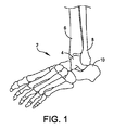
図1は足関節2の解剖学的図面を例示する。足関節2は、脛骨6および腓骨8と接触する距骨4を含む。踵骨10は、距骨4に隣接して位置する。足関節全置換において、距骨4および脛骨6は、距骨インプラントおよび脛骨インプラントの挿入を許容するように切除または切開されることができる。図2は足関節全置換物12が挿入された図1の足関節2を例示する。
FIG. 1 illustrates an anatomical drawing of an
足関節全置換システム12は、距骨プラットホーム14と、脛骨プラットホーム18と、を含む。距骨プラットホーム14は、距骨連接面16(または距骨円蓋)を規定する本体15を含む。ステム22は、距骨4に距骨プラットホーム14を固定するように距骨4内に延びる。脛骨プラットホーム18は、脛骨6内への設置のためにサイズ設定および構成される。脛骨プラットホーム18は、脛骨プラットホーム18を固定するように脛骨6内に延びる脛骨ステム24および連接面20を有する本体を含む。距骨関節面16および脛骨関節面20が互いに連接されるようにサイズ設定および構成される。関節面16,20は、自然関節を模倣する可動範囲および高さを回復するように除去される自然足関節面を代替する。脛骨インプラント18または距骨インプラント12を挿入する前および挿入する間に、一つ以上のホールが脛骨および/または距骨に形成されることができる。例えば、一部の実施例において、ホールは、距骨の底部から穿孔されて距骨を介して脛骨に延びる。ホールは、例えば、脛骨プラットホーム18のステム24を収容するように構成された6mmホールを含むことができる。
The ankle
関節面16,20は、例えば、ポリエチレン、高分子量ポリエチレン(HMWPE)、ゴム、チタン、チタン合金、クロムコバルト、手術用鋼、および/または任意の他の適する金属、セラミック、焼結ガラス、人工骨、および/またはその任意の組み合わせのような各種材料で製造されることができる。一部の実施例において、関節面16,20は、コーティング面を含むことができる。例えば、一部の実施例において、関節面16,20は、バイオフォーム材料のような多孔性材料が噴射されたプラズマであることができる。関節面16,20は、異なる材料を含むことができる。例えば、脛骨関節面20は、プラスチックまたは他の非金属材料を含むことができ、距骨関節面16は、金属面を含むことができる。当業者は、任意の適する材料の組み合わせが使用できることを認知するであろう。
The articulating surfaces 16, 20 may be, for example, polyethylene, high molecular weight polyethylene (HMWPE), rubber, titanium, titanium alloys, chromium cobalt, surgical steel, and / or any other suitable metal, ceramic, sintered glass, artificial bone. , And / or any combination thereof. In some embodiments, articulating
図3は一つ以上のフィン106を有するステム104を含むインプラント102の一実施例の側面図である。インプラント102は、連接面106と骨接触面108とを含む本体を含む。関節連接面106は、骨および/またはインプラントが連接面106と接触されて連接されることを許容するようにサイズ設定および構成される。例えば、一部の実施例において、インプラント102は、距骨インプラントを含む。連接面106は、設置後、脛骨および/または脛骨インプラントがインプラント102と接触されて連接されることを許容するようにサイズ設定および構成される。他の実施例において、連接面106は、追加および/または代替の骨および/またはインプラントの連接を許容するようにサイズ設定および構成されることができる。
FIG. 3 is a side view of one embodiment of an
本体104は、連接面106の反対側に位置する骨接触面108をさらに含む。骨接触面108は、手術中に用意された骨表面と接続されるように構成される。例えば、一部の実施例において、骨接触面108は、インプラント102を骨に結合するために、切除された距骨のような切除された骨表面と接続されるように構成される。一部の実施例において、骨接触面108は、通常の平面を含む。他の実施例において、骨接触面108は、凹面を含む。一部の実施例において、例えば、外周のような骨接触面108の一部のみが手術中に用意された骨表面と接続される。骨接触面108は、骨に対して適切な位置および/または整列でインプラント102を維持するようにサイズ設定および構成されたインプラント102のエッジに位置する表面リップを含むことができる。一部の実施例において、骨接触面108は、多数の骨接触点/面を含む。
The
ステム110は、骨接触面108に対して斜めに縦方向に延びる。ステム110は、手術中に骨に形成されるホール内に挿入されるようにサイズ設定および構成される。ステム110は、骨接触面108から所定距離だけ延びる。一部の実施例において、ステム110は、本体104の厚さ未満、同等または超過の所定距離だけ延びる。例えば、ステム110は、本体104の連接面106と骨接触面108との距離と同等な距離だけ延びることができる。ステム110は、骨接触面108から任意の適する角度で延びることができる。例えば、様々な実施例において、ステム110は、骨接触面108から0〜180度の角度で延びることができる。
The
ステム110は、ステム110に対して回転、並進、および/または引抜き抵抗力を提供するように構成された一つ以上の特徴部を含む。例示された実施例において、ステム110は、一つ以上のフィン112a,112bを含む。フィン112a,112bは、骨接触面108およびステム110から延びる。フィン112a,112bは、インプラント102が骨に結合される際に、インプラント102に前方/後方安定性、縦方向安定性、および内側/外側安定性を提供する。フィン112a,112bは、手術中に骨に形成されるチャネル内に挿入される。例えば、一実施例において、フィン112a,112bは、距骨切除手続きの間に距骨に形成されるフィンチャネル内に挿入される。フィン112a,112bは、チャネルの側壁と接触して骨に対してインプラント102を所定位置および整列に維持する。図4はインプラント102の正面図を例示する。一部の実施例において、インプラント102の本体104は、移植の間に距骨インプラントの操作を許容するためにハンドル(図示せず)を収容するようにサイズ設定および構成された一つ以上のホール114a,114bを規定する。
一部の実施例において、インプラント102は、軸方向抵抗力を提供するように骨に結合される。例えば、一実施例において、インプラント102は、骨に接合される。インプラントは、骨接触面108および/またはステム110で骨に接合されることができる。他の例として、一実施例において、インプラント102は、骨に形成されるホール内に圧入される。ホールは、圧入締結の間にステム110を収容するようにサイズ設定および構成される。インプラント102は、例えば、接合および骨との圧入締結のような任意の他の適する方法および/または任意の方法の組み合わせにより骨に結合されることができる。
In some embodiments, the
図5はインプラント102の底面図を例示する。図4に図示されるように、ステム110およびフィン112a,112bは、骨接触面108から縦方向に延びる。二つのフィン112a,112bが例示されるが、インプラント102は、一つ以上のフィンのうち任意の数を含むことができるという点が認知されるであろう。フィン112a,122bは、骨接触面108からステム110まで延びる半円形部分を含む。フィン112a,112bは、半円形として例示されるが、フィンは、例えば、長方形、三角形および/または任意の他の適する形状のような任意の適する形状を含むことができるという点が認知されるであろう。
FIG. 5 illustrates a bottom view of the
図6はスプライン218が形成されたステム210を含むインプラント202の一実施例の側面図を例示する。図7はインプラント202の底面図を例示する。インプラント202は、前記図3〜図5を参照して説明されるインプラント102と類似する。インプラント202は、インプラント本体204を含む。インプラント本体204は、連接面206および骨接触面208を規定する。ステム210は、骨接触面208から縦方向に延びる。ステム210は、骨に対してインプラント202に回転、並進、および/または引抜き抵抗力を提供するように構成された一つ以上の特徴部を含む。
FIG. 6 illustrates a side view of one embodiment of an
例示された実施例において、一つ以上の特徴部は、スプライン218を含む。スプライン218は、複数の鋸歯220a〜220eを含む。複数の鋸歯220a〜220eは、前方/後方安定性、回転安定性、および内側/外側安定性を提供するように構成される。一部の実施例において、複数の鋸歯220a〜220eは、骨内のホールに形成される複数の溝と接続されるように構成される。鋸歯220a〜220eは、骨に対してインプラント202の移動および回転を防止するようにホールに形成される溝と接続される。
In the illustrated embodiment, the one or more features include
図8はインプラント202の正面図を例示する。インプラント202の本体204は、インプラント202を一つ以上の追加インプラントに結合するようにサイズ設定および構成された一つ以上のホール214a,214bを規定することができる。例えば、一部の実施例において、インプラント202は、距骨に結合されて距骨円蓋を収容するように構成された距骨円蓋プラットホームを含む。複数のホール214a,214bは、インプラント202を距骨円蓋にメイティング(mating)するために距骨円蓋の一つ以上のメイティング特徴部を収容するように構成される。他の実施例において、複数のホール214a,214bは、例えば、脛骨インプラントのような隣接インプラントと結合されてインプラント202および隣接インプラントを所定間隔/整列に維持することができる。
FIG. 8 illustrates a front view of the
図9は複数のセレーション332が形成された三角形ステム310を含むインプラント302の一実施例の側面図を例示する。図10はインプラント302の底面図を例示する。インプラント302は、前記図3〜図5を参照して説明されるインプラント102と類似する。インプラント302は、インプラント本体304を含む。インプラント本体304は、連接面306および骨接触面308を規定する。ステム310は、骨接触面308から縦方向に延びる。ステム310は、骨に対してインプラント302に回転、並進、および/または引抜き抵抗力を提供するように構成された一つ以上の特徴部を含む。
FIG. 9 illustrates a side view of one embodiment of an
三角形ステム310は、第1脚部330aと、第2脚部330bと、第3脚部330cと、を含む。一部の実施例において、複数の脚部330a〜330cは、ステム310の周りに均等に離隔されている。複数の脚部330a〜330cそれぞれは、脚部330a〜330cの外側エッジ上に形成される複数のセレーション332を含む。ステム310は、例えば、距骨のような骨に形成されるホール内に挿入されることができる。ホールは、長方形、正方形、円、または他の断面形状のようなステム310を収容する任意の適する形状を含むことができる。複数の脚部330a〜330cは、前方/後方動作、回転動作、および/または内側/外側動作を防止する。複数のセレーション332は、ステム310に引抜き抵抗力を提供するように構成される。
The
図10はインプラント302の傾斜底面図である。傾斜底面図は、それぞれの脚部330a〜330cの鋸歯部332を例示する。脚部330a〜330cは、骨接触面308から縦方向にそれぞれ延びる。例示された実施例において、脚部330a〜330cは、ステム310により規定される周りに均等に離隔されている。他の実施例において、それぞれの脚部330a〜330cは、不均等な距離および/または角度で他の脚部それぞれから分離されることができる。例えば、第1脚部330aは、第1角度で第2脚部から分離され、第2角度で第3脚部から分離されることができる。第2および第3脚部は、第3角度で分離されることができる。
FIG. 10 is an inclined bottom view of the
図11はインプラント302の底面図を例示する。底面図は、ステム310の三角形、またはクリスマスツリー形状を例示する。ステム310の形状は、前方/後方安定性、回転安定性、および内側/外側安定性を提供する。一部の実施例において、脚部330a〜330cのエッジは、追加安定性を提供するためにエッジ330a〜330cが骨に噛み合うか骨内に食い込むことを許容するように鋭い。また、セレーション332は、追加安定性および引抜き抵抗力を提供するために鋭いことができる。
FIG. 11 illustrates a bottom view of the
図12はインプラント302の正面図を例示する。インプラント302の本体304は、インプラント302を一つ以上の追加インプラントに結合するようにサイズ設定および構成された一つ以上のホール314a,314bを規定することができる。例えば、一部の実施例において、インプラント302は、距骨に結合されて距骨円蓋を収容するように構成された距骨円蓋プラットホームを含む。複数のホール314a,314bは、距骨円蓋をインプラント302にメイティングするために、距骨円蓋の一つ以上のメイティング特徴部を収容するように構成される。他の実施例において、複数のホール314a,314bは、例えば、脛骨インプラントのような隣接インプラントに結合されてインプラント302および隣接インプラントを所定間隔/整列に維持することができる。
FIG. 12 illustrates a front view of the
様々な実施例において、インプラントが開示される。インプラントは、骨接触面および連接面を有する本体を含む。ステムは、骨接触面から縦方向に延びる。少なくとも一つのフィンは、ステムおよび本体に結合される。 In various embodiments, an implant is disclosed. The implant includes a body having a bone contacting surface and an articulating surface. The stem extends longitudinally from the bone contacting surface. At least one fin is coupled to the stem and the body.
一部の実施例において、少なくとも一つのフィンは、前方/後方移動、回転移動、および内側/外側移動を防止するために骨に形成されるチャネル内に収容されるようにサイズ設定および構成される。 In some embodiments, the at least one fin is sized and configured to be received in a channel formed in the bone to prevent anterior / posterior movement, rotational movement, and medial / lateral movement. .
一部の実施例において、少なくとも一つのフィンは、楔状フィンを含む。
一部の実施例において、楔状フィンは、ステムに結合される第1平坦エッジと、本体に結合される第2平坦エッジと、第1平坦エッジの端部から第2平坦エッジの端部まで延びるアーチ状エッジと、を含む。
In some embodiments, the at least one fin includes a wedge fin.
In some embodiments, the wedge fin extends from the end of the first flat edge to the end of the second flat edge, the first flat edge coupled to the stem, the second flat edge coupled to the body. Arcuate edges.
一部の実施例において、インプラントは、ステムの第1側上に位置する第1フィンと、フィンの第2側上に位置する第2フィンと、を含む。 In some embodiments, the implant includes a first fin located on the first side of the stem and a second fin located on the second side of the fin.
一部の実施例において、本体は、インプラントを配置するための道具を収容するようにサイズ設定および構成された少なくとも一つの道具ホールを規定する。 In some embodiments, the body defines at least one tool hole sized and configured to receive a tool for placing the implant.
一部の実施例において、ステムは、本体から所定距離だけ延び、所定距離は、本体の厚さ未満である。 In some embodiments, the stem extends a predetermined distance from the body, the predetermined distance being less than the thickness of the body.
一部の実施例において、連接面は、距骨円蓋を模倣するようにサイズ設定および構成される。 In some embodiments, the articulating surface is sized and configured to mimic the talus cap.
様々な実施例において、インプラントが開示される。インプラントは、骨接触面および連接面を有する本体を含む。ステムは、骨接触面から縦方向に延びる。スプラインは、ステムの周りに形成される。 In various embodiments, an implant is disclosed. The implant includes a body having a bone contacting surface and an articulating surface. The stem extends longitudinally from the bone contacting surface. A spline is formed around the stem.
一部の実施例において、スプラインは、前方/後方移動、回転移動、および内側/外側移動を防止するために骨に形成されるチャネル内に収容されるようにサイズ設定および構成される。 In some embodiments, the spline is sized and configured to be received in a channel formed in the bone to prevent forward / backward movement, rotational movement, and medial / lateral movement.
一部の実施例において、スプラインは、ステムの周りに配置される複数の均等に離隔した鋸歯を含む。 In some embodiments, the spline includes a plurality of evenly spaced saw teeth disposed about the stem.
一部の実施例において、本体は、インプラントを配置するための道具を収容するようにサイズ設定および構成された少なくとも一つの道具ホールを規定する。 In some embodiments, the body defines at least one tool hole sized and configured to receive a tool for placing the implant.
一部の実施例において、ステムは、本体から所定距離だけ延び、所定距離は、本体の厚さ未満である。 In some embodiments, the stem extends a predetermined distance from the body, the predetermined distance being less than the thickness of the body.
一部の実施例において、連接面は、距骨円蓋を模倣するようにサイズ設定および構成される。 In some embodiments, the articulating surface is sized and configured to mimic the talus cap.
様々な実施例において、インプラントが開示される。インプラントは、骨接触面および連接面を有する本体を含む。第1脚部、第2脚部、および第3脚部を有する三角形ステムは、本体から縦方向に延びる。第1脚部、第2脚部、または第3脚部の少なくとも一つは、その上に形成された複数のセレーションを規定する。 In various embodiments, an implant is disclosed. The implant includes a body having a bone contacting surface and an articulating surface. A triangular stem having a first leg, a second leg, and a third leg extends longitudinally from the body. At least one of the first leg, the second leg, or the third leg defines a plurality of serrations formed thereon.
一部の実施例において、三角形ステムは、回転移動、前方/後方移動、および内側/外側移動を防止するようにサイズ設定および構成され、複数のセレーションは、ステムに引抜き抵抗力を提供する。 In some embodiments, the triangular stem is sized and configured to prevent rotational movement, forward / backward movement, and inward / outward movement, and the plurality of serrations provide pull-out resistance to the stem.
一部の実施例において、第1脚部、第2脚部、および第3脚部は、それぞれ先鋭化したエッジを含む。 In some embodiments, the first leg, the second leg, and the third leg each include a sharpened edge.
一部の実施例において、本体は、インプラントを配置するための道具を収容するようにサイズ設定および構成された少なくとも一つの道具ホールを規定する。 In some embodiments, the body defines at least one tool hole sized and configured to receive a tool for placing the implant.
一部の実施例において、ステムは、本体から所定距離だけ延び、所定距離は、本体の厚さ未満である。 In some embodiments, the stem extends a predetermined distance from the body, the predetermined distance being less than the thickness of the body.
一部の実施例において、連接面は、距骨円蓋を模倣するようにサイズ設定および構成される。 In some embodiments, the articulating surface is sized and configured to mimic the talus cap.
本発明対象が例示的な実施例に関して記載されているが、本発明はこれに制限されない。むしろ、別添の請求項は、当業者により行われうる他の変形および実施例を含むように広範に解釈されるべきである。 Although the subject of the invention has been described with reference to exemplary embodiments, the invention is not limited thereto. Rather, the appended claims should be construed broadly to include other variations and embodiments that can be made by those skilled in the art.
Claims (21)
少なくとも一つの骨接触面から縦方向に延びるステムと、
前記ステムおよび前記本体に結合される少なくとも一つのフィンと、を含む、インプラント。 A body including a bone contacting surface and an articulating surface;
A stem extending longitudinally from at least one bone contacting surface;
An implant comprising: at least one fin coupled to the stem and the body.
前記少なくとも一つの骨接触面から縦方向に延びるステムと、
前記ステムの周りに形成されるスプラインと、を含む、インプラント。 A body including at least one bone contacting surface and an articulating surface;
A stem extending longitudinally from the at least one bone contacting surface;
An implant comprising: a spline formed around the stem.
前記本体から縦方向に延びる第1脚部、第2脚部、および第3脚部を有する三角形ステムであって、前記第1脚部、前記第2脚部、および前記第3脚部の少なくとも一つは、その上に形成された複数のセレーションを規定する三角形ステムと、を含む、インプラント。 A body including a bone contacting surface and an articulating surface;
A triangular stem having a first leg, a second leg, and a third leg extending longitudinally from the main body, wherein at least one of the first leg, the second leg, and the third leg An implant comprising a triangular stem defining a plurality of serrations formed thereon.
Applications Claiming Priority (1)
| Application Number | Priority Date | Filing Date | Title |
|---|---|---|---|
| PCT/US2014/064572 WO2016073001A1 (en) | 2014-11-07 | 2014-11-07 | Talar dome fixation stem |
Publications (1)
| Publication Number | Publication Date |
|---|---|
| JP2017501013A true JP2017501013A (en) | 2017-01-12 |
Family
ID=55867659
Family Applications (1)
| Application Number | Title | Priority Date | Filing Date |
|---|---|---|---|
| JP2016562727A Pending JP2017501013A (en) | 2014-11-07 | 2014-11-07 | Talar annulus fixation stem |
Country Status (7)
| Country | Link |
|---|---|
| US (2) | US9579210B2 (en) |
| EP (2) | EP3679901B1 (en) |
| JP (1) | JP2017501013A (en) |
| CN (1) | CN106029009A (en) |
| AU (3) | AU2014331640B2 (en) |
| CA (3) | CA2889245C (en) |
| WO (1) | WO2016073001A1 (en) |
Cited By (2)
| Publication number | Priority date | Publication date | Assignee | Title |
|---|---|---|---|---|
| WO2019045411A1 (en) * | 2017-08-29 | 2019-03-07 | 주식회사 코렌텍 | Artificial ankle joint talus component |
| WO2019045412A1 (en) * | 2017-08-29 | 2019-03-07 | 주식회사 코렌텍 | Artificial ankle joint tibia component |
Families Citing this family (14)
| Publication number | Priority date | Publication date | Assignee | Title |
|---|---|---|---|---|
| JP2017501013A (en) * | 2014-11-07 | 2017-01-12 | ライト メディカル テクノロジー インコーポレイテッドWright Medical Technology, Inc. | Talar annulus fixation stem |
| AU2016388305B2 (en) * | 2015-01-20 | 2019-06-06 | Advita Ortho, LLC. | Talar implant for modifying joint kinematics |
| CN105997307B (en) * | 2016-05-10 | 2017-12-19 | 上海交通大学医学院附属瑞金医院 | 3D printing-based repair and reconstruction method for large-scale talus osteochondral injury |
| US20170340450A1 (en) * | 2016-05-25 | 2017-11-30 | Arbelaez Jose Bernardo Toro | Reverse Ankle Replacement System |
| US12083027B2 (en) | 2017-03-02 | 2024-09-10 | Optimotion Implants LLC | Universal femoral trial system and methods |
| US11406502B2 (en) | 2017-03-02 | 2022-08-09 | Optimotion Implants LLC | Orthopedic implants and methods |
| US11039938B2 (en) | 2017-07-26 | 2021-06-22 | Optimotion Implants LLC | Modular knee prothesis |
| EP3459501B8 (en) * | 2017-09-22 | 2021-01-20 | Stryker European Operations Holdings LLC | Talar ankle implant |
| AU2019302325B2 (en) | 2018-04-24 | 2024-05-02 | Paragon 28, Inc. | Implants and methods of use and assembly |
| US10912652B2 (en) | 2018-07-09 | 2021-02-09 | Arthrex, Inc. | Arthroplasty implant systems for generating and applying dynamic compression |
| CN110856673B (en) * | 2018-08-24 | 2024-11-08 | 上海三友医疗器械股份有限公司 | Talus implant |
| CN110090096A (en) * | 2019-04-26 | 2019-08-06 | 中国人民解放军联勤保障部队第九二〇医院 | A kind of bionical cooperation black box of high temporal shin bone-astragalus |
| CN110013364A (en) * | 2019-04-26 | 2019-07-16 | 中国人民解放军联勤保障部队第九二〇医院 | A bionic fixation-resistant talus replacement part for the upper end of the talus with high conformability |
| EP4041126A4 (en) * | 2020-01-03 | 2023-08-30 | Wright Medical Technology, Inc. | ANKLE PROSTHESES |
Citations (3)
| Publication number | Priority date | Publication date | Assignee | Title |
|---|---|---|---|---|
| US20040167631A1 (en) * | 2003-02-21 | 2004-08-26 | Kenny Luchesi | Fixation surface for ankle prosthesis |
| US20090265011A1 (en) * | 2008-04-17 | 2009-10-22 | Mandell Steven L | Femoral component of an artificial knee joint |
| JP2011115440A (en) * | 2009-12-04 | 2011-06-16 | Nakashima Medical Co Ltd | Ankle prosthesis |
Family Cites Families (85)
| Publication number | Priority date | Publication date | Assignee | Title |
|---|---|---|---|---|
| US3872519A (en) * | 1974-04-04 | 1975-03-25 | Nicholas J Giannestras | Total ankle prosthesis |
| US3987500A (en) | 1976-01-28 | 1976-10-26 | Schlein Allen P | Surgically implantable total ankle prosthesis |
| CH607579A5 (en) * | 1976-11-15 | 1978-09-15 | Sulzer Ag | |
| US4470158A (en) | 1978-03-10 | 1984-09-11 | Biomedical Engineering Corp. | Joint endoprosthesis |
| US4624673A (en) * | 1982-01-21 | 1986-11-25 | United States Medical Corporation | Device system for dental prosthesis fixation to bone |
| US4759767A (en) * | 1987-08-10 | 1988-07-26 | Dow Corning Wright Corporation | Prosthesis for tibial component of knee joint |
| DE8816847U1 (en) | 1988-04-01 | 1990-11-08 | Metalpraecis Berchem + Schaberg Gesellschaft für Metallformgebung mbH, 4650 Gelsenkirchen | Joint prosthesis, especially hip joint prosthesis |
| FR2676917B1 (en) | 1991-05-29 | 1993-08-27 | Omci | ANKLE PROSTHESIS. |
| GB9201231D0 (en) * | 1992-01-21 | 1992-03-11 | Howmedica | Tibial element for a replacement knee prosthesis |
| US5326365A (en) * | 1992-04-10 | 1994-07-05 | Alvine Franklin G | Ankle implant |
| EP0607749A1 (en) * | 1993-01-21 | 1994-07-27 | SULZER Medizinaltechnik AG | Artificial wrist joint |
| US5326366A (en) * | 1993-02-16 | 1994-07-05 | Wright Medical Technology, Inc. | Biomechanical great toe implant |
| FR2702368B1 (en) * | 1993-03-10 | 1995-06-09 | Medinov Sa | Tibial implant for knee prosthesis. |
| US5571203A (en) * | 1993-06-18 | 1996-11-05 | Masini; Michael A. | Bone-conserving hip system |
| US5480445A (en) * | 1994-06-09 | 1996-01-02 | Intermedics Orthopedics, Inc. | Interlocking tibial prosthesis |
| US5489310A (en) | 1994-06-27 | 1996-02-06 | Mikhail; W. E. Michael | Universal glenoid shoulder prosthesis and method for implanting |
| DE29500476U1 (en) * | 1995-01-13 | 1995-08-03 | Thabe, Heiner, Dr.med., 55543 Bad Kreuznach | Prosthetic wrist |
| US8771365B2 (en) * | 2009-02-25 | 2014-07-08 | Conformis, Inc. | Patient-adapted and improved orthopedic implants, designs, and related tools |
| EP0956836B1 (en) * | 1998-05-13 | 2004-07-28 | DePuy Products, Inc. | Tibial tray with adjustable keel |
| US6443991B1 (en) * | 1998-09-21 | 2002-09-03 | Depuy Orthopaedics, Inc. | Posterior stabilized mobile bearing knee |
| US6251143B1 (en) * | 1999-06-04 | 2001-06-26 | Depuy Orthopaedics, Inc. | Cartilage repair unit |
| AU780719B2 (en) * | 1999-07-02 | 2005-04-14 | Spine Solutions Inc. | Intervertebral implant |
| US6379388B1 (en) * | 1999-12-08 | 2002-04-30 | Ortho Development Corporation | Tibial prosthesis locking system and method of repairing knee joint |
| US6575986B2 (en) * | 2001-02-26 | 2003-06-10 | Ethicon, Inc. | Scaffold fixation device for use in articular cartilage repair |
| US6743232B2 (en) * | 2001-02-26 | 2004-06-01 | David W. Overaker | Tissue scaffold anchor for cartilage repair |
| US6616697B2 (en) * | 2001-03-13 | 2003-09-09 | Nicholas G. Sotereanos | Hip implant assembly |
| US8753402B2 (en) * | 2001-07-27 | 2014-06-17 | Biomet Manufacturing, Llc | Modular humeral head resurfacing system |
| US6848152B2 (en) * | 2001-08-31 | 2005-02-01 | Quill Medical, Inc. | Method of forming barbs on a suture and apparatus for performing same |
| US7175667B2 (en) * | 2001-11-29 | 2007-02-13 | Gerald Anthony Briden Saunders | Metatarsophalangeal resurfacing joint |
| AUPS038802A0 (en) * | 2002-02-08 | 2002-02-28 | Portland Orthopaedics Pty Limited | Modulear prosthesis with adjustable taper |
| US7182786B2 (en) * | 2002-04-25 | 2007-02-27 | Zimmer Technology, Inc. | Modular bone implant, tool, and method |
| US6863691B2 (en) * | 2002-04-29 | 2005-03-08 | Timothy J. Short | Ankle implant |
| DE10220591B4 (en) * | 2002-05-08 | 2004-03-18 | Mathys Medizinaltechnik Ag | Joint prosthesis with an intermediate element with different radii of curvature |
| US6939380B2 (en) * | 2002-12-23 | 2005-09-06 | Depuy Products, Inc. | Mobile talar component for total ankle replacement implant |
| US7011687B2 (en) * | 2003-01-06 | 2006-03-14 | Depuy Products, Inc. | Ankle prosthesis with a front loading bearing and associated method |
| US20040143336A1 (en) * | 2003-01-22 | 2004-07-22 | Brian Burkinshaw | Two-piece modular patellar prosthetic system |
| US20040186585A1 (en) * | 2003-03-21 | 2004-09-23 | Lawrence Feiwell | Sphere-on-sphere ankle prosthesis |
| EP1686932B1 (en) * | 2003-06-27 | 2010-01-06 | ABS Corporation | System for ankle arthroplasty |
| DE112004001893B4 (en) | 2003-10-09 | 2018-06-21 | Omni Life Science, Inc. | Conical joint prosthesis |
| US7485147B2 (en) * | 2004-02-13 | 2009-02-03 | Pappas Michael J | Ankle prosthesis including tibial component having peripheral wall for preventing the formation of bone cysts |
| US7323012B1 (en) * | 2004-03-17 | 2008-01-29 | Biomet Manufacturing Corp. | Ankle implant |
| US20050288792A1 (en) * | 2004-06-23 | 2005-12-29 | Landes Mark D | Modular ankle prosthesis and associated method |
| US20060142870A1 (en) * | 2004-08-19 | 2006-06-29 | Shawn Robinson | Modular total ankle prosthesis apparatuses, systems and methods, and systems and methods for bone resection and prosthetic implantation |
| US7883653B2 (en) * | 2004-12-30 | 2011-02-08 | Depuy Products, Inc. | Method of making an implantable orthopaedic bearing |
| WO2007084846A2 (en) * | 2006-01-20 | 2007-07-26 | Hasselman Carl T | Method of preparing an ankle joint for replacement, joint prosthesis, and cutting alignment apparatus for use in performing an arthroplasty procedure |
| US8652211B1 (en) * | 2006-01-26 | 2014-02-18 | Gerald J. Jerry, JR. | Modular toe joint implant |
| US7837717B2 (en) * | 2006-03-24 | 2010-11-23 | Depuy Products, Inc. | Fastening system for internal fixation |
| US9278006B2 (en) * | 2006-10-26 | 2016-03-08 | European Foot Platform Sc | Ankle prosthesis with neutral position adjustment |
| US8715359B2 (en) * | 2009-10-30 | 2014-05-06 | Depuy (Ireland) | Prosthesis for cemented fixation and method for making the prosthesis |
| US20110035018A1 (en) * | 2007-09-25 | 2011-02-10 | Depuy Products, Inc. | Prosthesis with composite component |
| US10398561B2 (en) * | 2007-09-26 | 2019-09-03 | DePuy Synthes Products, Inc. | Talar implant system and method |
| US8641732B1 (en) * | 2008-02-26 | 2014-02-04 | Ethicon, Inc. | Self-retaining suture with variable dimension filament and method |
| US9216085B2 (en) * | 2008-02-28 | 2015-12-22 | Biopoly, Llc | Partial joint resurfacing implant, instrumentation, and method |
| US8696755B2 (en) * | 2008-04-17 | 2014-04-15 | Steven L. Mandell | Tibial component of an artificial knee joint |
| US20100057216A1 (en) * | 2008-07-23 | 2010-03-04 | Jamy Gannoe | System and method for joint resurfacing with dynamic fixation |
| EP2334263B1 (en) * | 2008-09-30 | 2015-01-07 | Wright Medical Technology, Inc. | Ankle prosthesis and a tibial component therefor |
| US8574305B2 (en) * | 2009-04-29 | 2013-11-05 | Foot Innovations, Llc | System and method for modifying talocalcaneal relationship in a foot |
| US9005301B2 (en) * | 2009-04-29 | 2015-04-14 | Foot Innovations, Llc | System and method for modifying talocalcaneal relationship in a foot |
| CA2760954A1 (en) * | 2009-05-19 | 2010-11-25 | Synthes Usa, Llc | Dynamic trial implants |
| US20110035019A1 (en) * | 2009-07-09 | 2011-02-10 | Wright State University | Total ankle replacement system |
| US9095453B2 (en) * | 2009-08-11 | 2015-08-04 | Michael D. Ries | Position adjustable trial systems for prosthetic implants |
| CA2771555C (en) * | 2009-08-25 | 2016-09-13 | Fellowship Of Orthopaedic Researchers, Inc. | Trochlear implants and methods of use |
| US9492281B2 (en) * | 2010-02-19 | 2016-11-15 | European Foot Platform Sc | Ankle prosthesis with simplified adjustment |
| US20110257758A1 (en) * | 2010-03-05 | 2011-10-20 | Biomet Manufacturing Corp. | Splined tapered modular distal stem with proximal porous coating |
| US8591596B2 (en) * | 2010-05-28 | 2013-11-26 | DePuy Synthes Products, LLC | Semi-constrained ankle prosthesis having a rotating bearing insert |
| US20120010718A1 (en) * | 2010-07-08 | 2012-01-12 | Still Gregory P | Partial ankle joint replacement implant |
| US8932364B2 (en) * | 2010-07-14 | 2015-01-13 | Howmedica Osteonics Corp. | Prosthetic knee void filers with splined fixation |
| WO2012021764A2 (en) * | 2010-08-13 | 2012-02-16 | Smith & Nephew, Inc. | Orthopaedic implants and methods |
| US8690956B2 (en) * | 2010-08-23 | 2014-04-08 | Fellowship Of Orthopaedic Researchers, Inc. | Talar implants and methods of use |
| JP2013539390A (en) * | 2010-09-04 | 2013-10-24 | コンセプツ イン メディシン シックス,エルエルシー | Talent joint prosthesis and method of transplantation thereof |
| US9468532B2 (en) * | 2011-11-01 | 2016-10-18 | Adam D. Perler | Semi constrained polyaxial endoprosthetic ankle joint replacement implant |
| US8668743B2 (en) * | 2010-11-02 | 2014-03-11 | Adam D. Perler | Prosthetic device with multi-axis dual bearing assembly and methods for resection |
| US20120245701A1 (en) * | 2011-03-24 | 2012-09-27 | Rudolf Zak | Hemi Ankle Implant |
| CN102125473B (en) * | 2011-04-18 | 2013-02-13 | 张纯朴 | Absorbable ankle fusion device |
| US20120271430A1 (en) * | 2011-04-22 | 2012-10-25 | Medicinelodge, Inc. Dba Imds Co-Innovation | Ankle arthroplasty |
| US8845750B2 (en) * | 2011-05-16 | 2014-09-30 | Jerome A. Slavitt | Joint resurfacing prosthetic implant system |
| US8979937B2 (en) * | 2011-09-27 | 2015-03-17 | Linares Medical Devices, Llc | Implantable ankle joint assembly with spherical inter-support |
| GB2500918A (en) * | 2012-04-05 | 2013-10-09 | Biomet Uk Healthcare Ltd | A prosthetic ankle with sliding engaging components |
| US20140018814A1 (en) * | 2012-07-10 | 2014-01-16 | Zimmer, Inc. | Cementing of an orthopedic implant |
| US9295554B2 (en) * | 2012-07-10 | 2016-03-29 | Zimmer, Inc. | Attachments for orthopedic implants |
| US20140081422A1 (en) * | 2012-09-10 | 2014-03-20 | Ortho Transmission, Llc | Transcutaneous Implant for Skeletal Attachment of External Prosthetic Devices |
| US9144500B2 (en) * | 2012-09-20 | 2015-09-29 | Michael G. Harding, Jr. | Ankle replacement devices and methods of making and using the same |
| US20140128985A1 (en) * | 2012-11-07 | 2014-05-08 | Roy W. Sanders | Joint Arthroplasty Systems, Methods, and Components |
| US9949839B2 (en) * | 2013-03-13 | 2018-04-24 | Wright Medical Technology, Inc. | Revision implant augments, systems, and methods |
| JP2017501013A (en) * | 2014-11-07 | 2017-01-12 | ライト メディカル テクノロジー インコーポレイテッドWright Medical Technology, Inc. | Talar annulus fixation stem |
-
2014
- 2014-11-07 JP JP2016562727A patent/JP2017501013A/en active Pending
- 2014-11-07 EP EP20155151.2A patent/EP3679901B1/en not_active Not-in-force
- 2014-11-07 CA CA2889245A patent/CA2889245C/en not_active Expired - Fee Related
- 2014-11-07 CA CA2998783A patent/CA2998783C/en not_active Expired - Fee Related
- 2014-11-07 CN CN201480037513.8A patent/CN106029009A/en active Pending
- 2014-11-07 US US14/404,800 patent/US9579210B2/en active Active
- 2014-11-07 WO PCT/US2014/064572 patent/WO2016073001A1/en not_active Ceased
- 2014-11-07 AU AU2014331640A patent/AU2014331640B2/en not_active Ceased
- 2014-11-07 CA CA3098070A patent/CA3098070A1/en not_active Abandoned
- 2014-11-07 EP EP14861167.6A patent/EP3215066B1/en active Active
-
2017
- 2017-01-13 US US15/406,026 patent/US20170128221A1/en not_active Abandoned
- 2017-01-13 AU AU2017200251A patent/AU2017200251B2/en not_active Ceased
-
2018
- 2018-10-30 AU AU2018256517A patent/AU2018256517A1/en not_active Abandoned
Patent Citations (3)
| Publication number | Priority date | Publication date | Assignee | Title |
|---|---|---|---|---|
| US20040167631A1 (en) * | 2003-02-21 | 2004-08-26 | Kenny Luchesi | Fixation surface for ankle prosthesis |
| US20090265011A1 (en) * | 2008-04-17 | 2009-10-22 | Mandell Steven L | Femoral component of an artificial knee joint |
| JP2011115440A (en) * | 2009-12-04 | 2011-06-16 | Nakashima Medical Co Ltd | Ankle prosthesis |
Cited By (9)
| Publication number | Priority date | Publication date | Assignee | Title |
|---|---|---|---|---|
| WO2019045411A1 (en) * | 2017-08-29 | 2019-03-07 | 주식회사 코렌텍 | Artificial ankle joint talus component |
| WO2019045412A1 (en) * | 2017-08-29 | 2019-03-07 | 주식회사 코렌텍 | Artificial ankle joint tibia component |
| KR20190023417A (en) * | 2017-08-29 | 2019-03-08 | 주식회사 코렌텍 | Talar component of artificial ankle joint |
| KR20190023419A (en) * | 2017-08-29 | 2019-03-08 | 주식회사 코렌텍 | Tibia component of artificial ankle joint |
| KR102018051B1 (en) * | 2017-08-29 | 2019-09-04 | 주식회사 코렌텍 | Tibia component of artificial ankle joint |
| KR102066837B1 (en) | 2017-08-29 | 2020-01-16 | 주식회사 코렌텍 | Talar component of artificial ankle joint |
| CN111050703A (en) * | 2017-08-29 | 2020-04-21 | 科润泰克株式会社 | Artificial ankle joint tibia element |
| US11690727B2 (en) | 2017-08-29 | 2023-07-04 | Corentec Co., Ltd. | Artificial ankle joint tibia component |
| CN111050703B (en) * | 2017-08-29 | 2023-09-19 | 科润泰克株式会社 | Artificial ankle tibia element |
Also Published As
| Publication number | Publication date |
|---|---|
| AU2014331640B2 (en) | 2017-02-16 |
| CN106029009A (en) | 2016-10-12 |
| AU2017200251A1 (en) | 2017-02-02 |
| US20160128842A1 (en) | 2016-05-12 |
| AU2014331640A1 (en) | 2016-05-26 |
| US20170128221A1 (en) | 2017-05-11 |
| EP3215066B1 (en) | 2020-02-26 |
| EP3679901A1 (en) | 2020-07-15 |
| EP3679901B1 (en) | 2022-03-02 |
| CA3098070A1 (en) | 2016-05-07 |
| CA2889245C (en) | 2018-05-01 |
| CA2998783A1 (en) | 2016-05-07 |
| CA2998783C (en) | 2020-12-15 |
| US9579210B2 (en) | 2017-02-28 |
| AU2017200251B2 (en) | 2018-08-16 |
| EP3215066A4 (en) | 2018-06-27 |
| WO2016073001A1 (en) | 2016-05-12 |
| AU2018256517A1 (en) | 2018-11-22 |
| CA2889245A1 (en) | 2016-05-07 |
| EP3215066A1 (en) | 2017-09-13 |
Similar Documents
| Publication | Publication Date | Title |
|---|---|---|
| JP2017501013A (en) | Talar annulus fixation stem | |
| US12383318B2 (en) | Orthopedic implant and methods of implanting and removing same | |
| JP6862492B2 (en) | Tibial trial system for knee prosthesis | |
| US8764842B2 (en) | Interphalangeal joint implant methods and apparatus | |
| US10729552B2 (en) | Implant configured for hammertoe and small bone fixation | |
| AU2014265029B2 (en) | Talar dome prosthesis | |
| JP6228661B2 (en) | Intramedullary ankle technology and systems | |
| US10716604B2 (en) | Bone fusing device for fusing phalanges | |
| JP6488313B2 (en) | Implant and drill guide | |
| GB2430625A (en) | Joint fusion peg | |
| CN107106299A (en) | Fixed mechanism for implantation piece | |
| NZ730679A (en) | A prosthetic intervertebral disc joint assembly | |
| US20220241082A1 (en) | Ankle prosthesis | |
| US20160106545A1 (en) | Artificial implant for trapeziometacarpal joint |
Legal Events
| Date | Code | Title | Description |
|---|---|---|---|
| A621 | Written request for application examination |
Free format text: JAPANESE INTERMEDIATE CODE: A621 Effective date: 20160705 |
|
| A977 | Report on retrieval |
Free format text: JAPANESE INTERMEDIATE CODE: A971007 Effective date: 20170428 |
|
| A131 | Notification of reasons for refusal |
Free format text: JAPANESE INTERMEDIATE CODE: A131 Effective date: 20170509 |
|
| A521 | Request for written amendment filed |
Free format text: JAPANESE INTERMEDIATE CODE: A523 Effective date: 20170809 |
|
| A131 | Notification of reasons for refusal |
Free format text: JAPANESE INTERMEDIATE CODE: A131 Effective date: 20171031 |
|
| A521 | Request for written amendment filed |
Free format text: JAPANESE INTERMEDIATE CODE: A523 Effective date: 20180129 |
|
| A02 | Decision of refusal |
Free format text: JAPANESE INTERMEDIATE CODE: A02 Effective date: 20180626 |