JP2017222007A - Electrochemical machining device and machining method - Google Patents
Electrochemical machining device and machining method Download PDFInfo
- Publication number
- JP2017222007A JP2017222007A JP2016119725A JP2016119725A JP2017222007A JP 2017222007 A JP2017222007 A JP 2017222007A JP 2016119725 A JP2016119725 A JP 2016119725A JP 2016119725 A JP2016119725 A JP 2016119725A JP 2017222007 A JP2017222007 A JP 2017222007A
- Authority
- JP
- Japan
- Prior art keywords
- electrode
- workpiece
- electrolytic
- internal passage
- gap
- Prior art date
- Legal status (The legal status is an assumption and is not a legal conclusion. Google has not performed a legal analysis and makes no representation as to the accuracy of the status listed.)
- Pending
Links
Images


Landscapes
- Electrical Discharge Machining, Electrochemical Machining, And Combined Machining (AREA)
Abstract
Description
本発明は、電解加工装置及び電解加工方法に関する。 The present invention relates to an electrolytic processing apparatus and an electrolytic processing method.
近年、切削加工に代わる新しい金属加工法として、電気化学加工ECM(Electro-Chemical Machining)が提案されている。ECMは、電極を陰極とし、被加工物を陽極とするとともに、それらを隙間を隔てて配置した上で、その隙間に電解液を流しながら電極と被加工物との間に電圧を印加することにより、電解作用により被加工物を加工する方法である。従来、この種の電解加工方法を用いた装置としては、特許文献1に記載の装置がある。
In recent years, electrochemical machining ECM (Electro-Chemical Machining) has been proposed as a new metal working method to replace cutting. The ECM uses an electrode as a cathode and a workpiece as an anode, and arranges them with a gap between them, and then applies a voltage between the electrode and the workpiece while flowing an electrolyte through the gap. Thus, the workpiece is processed by electrolytic action. Conventionally, there is an apparatus described in
特許文献1に記載の電解加工装置は、棒状電極と、ガイド部と、調整部とを備えている。棒状電極は、中心軸に沿って電解液を流す通路を有している。棒状電極は、ガイド部により支持されている。ガイド部には、棒状電極の通路からの電解液を装置外部に排出する排出路が設けられている。調整部は、ガイド部に取り付けられている。この電解加工装置では、調整部を操作することにより、ガイド部による棒状電極の支持方向を微調整することが可能となっている。また、棒状電極の支持方向を調整した後、棒状電極及びガイド部に対して光透過性疑似ワークを被せた状態で棒状電極の通路に電解液を流すことにより、電解液の流れを視認することができる。これにより、実際の電解加工前に電解液の滞留や偏流を確認しつつ、電極の支持方向を調整することができる。
The electrolytic processing apparatus described in
ところで、特許文献1に記載の電解加工装置のように、電解液の流れを目視で確認しつつ、調整部の操作により棒状電極の支持方向を調整するという方法を用いた場合、棒状電極の支持方向を調整し易くなるものの、棒状電極の支持方向を適切な方向に完全に一致させることは難しい。仮に棒状電極の支持方向が適切な方向から僅かにずれている場合、棒状電極と被加工物との間の隙間に偏りが生じる。棒状電極と被加工物との間の隙間に偏りがある状態のまま被加工物の加工を行った場合、被加工物の加工形状が不均一になる可能性があり、結果として加工精度を確保できないおそれがある。
By the way, like the electrolytic processing apparatus of
本発明は、こうした実情に鑑みてなされたものであり、その目的は、加工精度を向上させることのできる電解加工装置、及び電解加工方法を提供することにある。 The present invention has been made in view of such circumstances, and an object thereof is to provide an electrolytic processing apparatus and an electrolytic processing method capable of improving processing accuracy.
上記課題を解決するために、電解加工装置(20)は、円筒状の電極(30)と被加工物(10)との間の隙間に電解液を供給しつつ、電極と被加工物との間に電圧を印加することにより被加工物を加工する。電解加工装置は、電極と被加工物とを相対的に回転させる回転機構(50)を備える。電極は、電解液が流れる内部通路(31)と、内部通路から電極の外周面に貫通する複数のスリット(34)と、を有する。 In order to solve the above problems, the electrolytic processing apparatus (20) supplies an electrolytic solution to the gap between the cylindrical electrode (30) and the workpiece (10), and The workpiece is processed by applying a voltage between them. The electrolytic processing apparatus includes a rotation mechanism (50) that relatively rotates the electrode and the workpiece. The electrode has an internal passage (31) through which the electrolytic solution flows and a plurality of slits (34) penetrating from the internal passage to the outer peripheral surface of the electrode.
また、上記課題を解決するために、電解加工方法は、円筒状の電極(30)と被加工物(10)との間の隙間に電解液を供給しつつ、電極と被加工物との間に電圧を印加することにより被加工物を加工する。電極は、電解液が流れる内部通路(31)と、内部通路から電極の外周面に貫通する複数のスリット(34)と、を有する。電解加工方法は、電極の内部通路及びスリットに電解液を流すことにより、電極と被加工物との間の隙間に電解液を供給するステップと、電極と被加工物とを相対的に回転させつつ、被加工物を加工するステップと、を備える。 In order to solve the above-mentioned problem, an electrolytic processing method is provided between an electrode and a workpiece while supplying an electrolytic solution to a gap between the cylindrical electrode (30) and the workpiece (10). The workpiece is processed by applying a voltage to the workpiece. The electrode has an internal passage (31) through which the electrolytic solution flows and a plurality of slits (34) penetrating from the internal passage to the outer peripheral surface of the electrode. The electrolytic processing method includes a step of supplying an electrolytic solution to a gap between the electrode and the workpiece by flowing the electrolytic solution through the internal passage and slit of the electrode, and relatively rotating the electrode and the workpiece. And a step of processing the workpiece.
この構成及び方法によれば、仮に電極と被加工物との間の隙間に偏りが生じている場合でも、回転機構により電極と被加工物とを相対的に回転させることにより、隙間の偏りを均一化させることができる。これにより、被加工物の加工形状を均一化させることができるため、加工精度を向上させることができる。また、被加工物の電解加工により生成されるスラッジや水素等の通電阻害物質は、電極の内部通路及びスリットを流れる電解液により排出される。よって、通電阻害物質の堆積に起因する加工精度の悪化が抑制されるため、結果的に被加工物の加工精度を向上させることができる。 According to this configuration and method, even if the gap between the electrode and the workpiece is biased, the gap is biased by rotating the electrode and the workpiece relative to each other by the rotation mechanism. It can be made uniform. Thereby, since the processing shape of a workpiece can be made uniform, processing accuracy can be improved. Further, current-inhibiting substances such as sludge and hydrogen generated by electrolytic processing of the workpiece are discharged by the electrolytic solution flowing through the internal passages and slits of the electrode. Therefore, since the deterioration of the processing accuracy due to the accumulation of the current-inhibiting substance is suppressed, the processing accuracy of the workpiece can be improved as a result.
なお、上記手段、及び特許請求の範囲に記載の括弧内の符号は、後述する実施形態に記載の具体的手段との対応関係を示す一例である。 In addition, the code | symbol in the bracket | parenthesis as described in the said means and a claim is an example which shows a corresponding relationship with the specific means as described in embodiment mentioned later.
本発明によれば、加工精度を向上させることの可能な電解加工装置、及び電解加工方法を提供できる。 According to the present invention, it is possible to provide an electrolytic processing apparatus and an electrolytic processing method capable of improving processing accuracy.
以下、電解加工装置及び電解加工方法の一実施形態について説明する。
図1に示されるように、本実施形態の電解加工装置20は、被加工物10の内部の加工面150を加工する装置である。
Hereinafter, an embodiment of an electrolytic processing apparatus and an electrolytic processing method will be described.
As shown in FIG. 1, the
具体的には、被加工物10は、本体部11と、突出部12とを備えている。本体部11は、軸線m1を中心に円柱状に形成されている。突出部12は、本体部11の軸方向の一端面110から軸線m1に沿って円柱状に延びるように形成されている。本体部11及び突出部12には、第1内部通路13及び第2内部通路14が形成されている。第1内部通路13は、突出部12の先端面120から本体部11の内部まで軸線m1に沿って延びるように形成されている。第2内部通路14は、第1内部通路13における本体部11の内部まで延びた端部から本体部11の外周面に貫通するように形成されている。
Specifically, the
電解加工装置20は、被加工物10の第1内部通路13の内壁面のうち、第2内部通路14との接続部分よりも突出部12側にずれた部分に位置する加工面150を加工する。詳しくは、電解加工装置20は、電極30と、支持部材40と、回転機構50とを備えている。電解加工装置20は、電極30と被加工物10との間の隙間に電解液を流しながら電極30と被加工物10との間に電圧を印加することにより、電解作用により被加工物10の加工面150に窪み部を形成する。電解液としては、例えば硝酸ナトリウム(NaNO3)水溶液を用いることができる。
The
電極30は、軸線m1を中心に円筒状に形成されている。以下、軸線m1を、「電極30の中心軸」とも称する。電極30の先端部32は、被加工物10の第1内部通路13内に挿入されている。電極30は、被加工物10の第1内部通路13の内径よりも小さい外径を有している。すなわち、電極30の外周面と被加工物10の内周面との間には隙間が形成されている。この隙間は、電解液を流すための流路として利用される。
The
電極30の基端部は、回転機構50に連結されている。回転機構50は、電極30を軸線m1を中心に回転可能に支持するとともに、軸線m1を中心に矢印Rで示される方向に電極30と一体的に回転する。すなわち、回転機構50は、被加工物10に対して電極30を相対的に回転させる。回転機構50としては、例えば水流により回転するプロペラから伝達される動力を利用して回転する水力式の回転機構を用いることができる。水力式の回転機構の作動流体としては、例えば電解液と同一の流体を用いることができる。
A base end portion of the
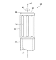
電極30の内部には、電解液が流れる内部通路31が形成されている。電極30の先端部32の外周面33は、被加工物10の加工面150に対向している。図2に示されるように、電極30の先端部外周面33の外径は、それ以外の部分の外径よりも大きくなっている。電極30の先端部外周面33には、複数のスリット34が形成されている。スリット34は、内部通路31から先端部外周面33に電極30を貫通するように形成されている。スリット34は、電極30の中心軸m1の方向に延びる長孔状に形成されている。詳しくは、スリット34における電極30の先端部32に近い端部を一端部340とし、一端部340とは反対側の端部を他端部341とするとき、スリット34は、一端部340の方が他端部341よりも電極30の回転方向Rの進角側に位置するような長孔状に形成されている。
An
電極30における先端部外周面33を除く外周面35は、絶縁性部材60により被覆されている。絶縁性部材60としては、例えば熱の付与により収縮する収縮チューブを用いることができる。電極30の先端部32にも、絶縁性部材61が設けられている。絶縁性部材61としては、例えば耐熱性の樹脂部材を用いることができる。絶縁性部材60,61により電極30と被加工物10との間の通電が阻害されることにより、被加工物10の電解作用が阻害される。これにより、電極30の先端部外周面33に対向する被加工物10の加工面150の部分だけを加工することができる。
The outer
図1に示されるように、支持部材40は、軸線m1を中心に有底円筒状に形成されており、その一端面41の中央部に凹状の挿入穴42を有している。この支持部材40の一端面41に被加工物10の一端面110が面接触するようにして、支持部材40に対して被加工物10が組み付けられる。支持部材40に被加工物10が組み付けられた際、挿入穴42に被加工物10の突出部12が挿入される。被加工物10の一端面110には、支持部材40の一端面41との間のシール性を確保するためのシール部材16が設けられている。
As shown in FIG. 1, the
挿入穴42の軸線m1に直交する断面形状は円形状に形成されている。挿入穴42は、被加工物10の突出部12の外径よりも大きい内径を有している。また、挿入穴42は、軸線m1に平行な方向における突出部12の長さよりも長い深さを有している。これにより、挿入穴42に被加工物10の突出部12が挿入された際、被加工物10の突出部12の外周面と支持部材40の挿入穴42の内周面との間に隙間が形成される。また、被加工物10の先端面120と支持部材40の挿入穴42の底面421との間にも、隙間が形成される。この隙間は、電解液が流れる流路として利用される。支持部材40には、挿入穴42の内周面から支持部材40の外周面に貫通する貫通孔44が形成されている。
The cross-sectional shape orthogonal to the axis m1 of the
支持部材40における挿入穴42の底面421の中央部には、凹部43が形成されている。凹部43の内部には、回転機構50が配置されている。支持部材40は、電極30及び回転機構50を軸線m1を中心に回転可能に支持している。
A
電解加工装置20は、電源装置70と、ポンプ80とを更に備えている。電源装置70は、電極30が陰極となり、被加工物10が陽極となるように、電極30と被加工物10との間にパルス電圧を印加する。ポンプ80は、被加工物10の外周面から第2内部通路14に電解液を圧送するとともに、支持部材40の外周面から貫通孔44に電解液を圧送する。
The
次に、本実施形態の電解加工装置20を用いた被加工物10の加工方法について詳しく説明する。
Next, the processing method of the
被加工物10を加工する際には、まず、図1に示されるように支持部材40に対して被加工物10を組み付ける。その後、矢印W1,W2で示されるように、ポンプ80により被加工物10の外周面から第2内部通路14に電解液を流入させるとともに、支持部材40の外周面から貫通孔44に電解液を流入させる。
When processing the
その際、被加工物10の第2内部通路14に流入した電解液は、第1内部通路13へと流れる。この電解液は、図3に矢印W1で示されるように、電極30の先端部外周面33と被加工物10の加工面150との間の隙間に供給されるとともに、矢印W3で示されるようにスリット34を介して電極30の内部通路31へと流れる。この電極30の内部通路31を流れる電解液は、図1に矢印W3で示されるように、支持部材40の外部に排出される。
At that time, the electrolyte flowing into the second
また、第2内部通路14に流入した電解液は、支持部材40の挿入穴42から、電極30の外周面と被加工物10の第1内部通路13の内壁面との間の隙間を流れる。この電解液は、図3に矢印W2で示されるように、電極30の先端部外周面33と被加工物10の加工面150との間の隙間に供給されるとともに、矢印W3で示されるようにスリット34を介して電極30の内部通路31へと流れ、支持部材40の外部に排出される。
In addition, the electrolyte flowing into the second
このようにして電極30の外周面と被加工物10の第1内部通路13の内壁面との間の隙間に電解液を供給した状態で、回転機構50により電極30を回転させつつ、電源装置70により電極30と被加工物10との間にパルス電圧を印加させる。これにより、電極30の先端部外周面33と被加工物10の加工面150との間が電解液を介して通電され、その電解作用により被加工物10の加工面150が加工される。その際、被加工物10の加工面150の電解により発生するスラッジや水素等の通電阻害物質は、図1及び図3に矢印W3で示される電解液の流れにより、電極30の内部通路31を介して支持部材40の外部に排出される。この電解加工装置20では、電源装置70によるパルス電圧の印加を所定時間繰り返し行うことで、被加工物10の加工面150を所定の寸法に加工する。これにより、被加工物10の電解加工が完了する。
In this manner, the electrolytic device is supplied to the gap between the outer peripheral surface of the
以上説明した本実施形態の電解加工装置20及び電解加工方法によれば、以下の(1)〜(4)に示される作用及び効果を得ることができる。
According to the
(1)被加工物10の加工精度を確保するためには、電極30の先端部外周面33と被加工物10の加工面150との間の隙間が均一であることが望ましい。しかしながら、支持部材40に被加工物10を取り付けた際に、組み付け誤差などにより、電極30の中心軸が軸線m1に対して僅かにずれるような場合が考えられる。この場合、電極30の先端部外周面33と被加工物10の加工面150との間の隙間に偏りが生じる。これが、加工精度を低下させる要因となる。
(1) In order to ensure the processing accuracy of the
この点、本実施形態の電解加工装置20及び電解加工方法によれば、回転機構50により被加工物10に対して電極30を相対的に回転させることにより、電極30の先端部外周面33と被加工物10の加工面150との間の隙間の偏りを均一化させることができる。これにより、被加工物10の加工面150の加工形状を均一化させることができるため、加工精度を向上させることができる。
In this regard, according to the
また、被加工物10の電解加工により生成される通電阻害物質は、電極30の先端部外周面33と被加工物10の加工面150との間の隙間からスリット34を通じて電極30の内部通路31へと流れる電解液により排出される。これにより、通電阻害物質の堆積に起因する加工精度の悪化が抑制されるため、結果的に被加工物10の加工精度を向上させることができるとともに、加工面150の面粗さを改善することもできる。
Further, the current-inhibiting substance generated by the electrolytic processing of the workpiece 10 passes through the
さらに、電極30の先端部外周面33に複数のスリット34が形成されている場合でも、電極30を回転させることにより、スリット34が被加工物10の加工面150の加工に及ぼす影響を防止することができる。よって、被加工物10の加工精度を確保することができる。
Further, even when a plurality of
(2)電解液は、電極30の先端部外周面33と被加工物10の加工面150との間の隙間からスリット34を通じて電極30の内部通路31に流れる。これにより、電解質の供給及び排出が行われ易くなるため、被加工物10の電解加工の精度を向上させることができる。
(2) The electrolytic solution flows into the
(3)スリット34は、電極30の先端部外周面33に形成されるとともに、電極30の中心軸m1の方向に延びる長孔状に形成されている。また、スリット34は、電極30の先端部32側の一端部340の方がその反対側の他端部341よりも電極30の回転方向Rの進角側に位置するように、電極30の中心軸m1に対して斜めに配置されている。これにより、電極30が回転した際に、スリット34が電解液の圧送を補助するプロペラとして機能するため、電解液の供給及び排出が行われ易くなる。結果的に、被加工物10の電解加工の精度を向上させることができる。
(3) The
(4)電極30における被加工物10の加工面150に対向する部分、すなわち先端部外周面33以外の部分には、絶縁性部材60,61が設けられている。これにより、より的確に被加工物10の加工面150だけを加工することが可能となる。
(4) Insulating
なお、上記実施形態は、以下の形態にて実施することもできる。
・スリット34の形状は適宜変更可能である。例えば図4に示されるように、スリット34は、電極30の中心軸m1に平行な長孔状に形成されていてもよい。また、図5に示されるように、スリット34は、丸孔状に形成されていてもよい。
In addition, the said embodiment can also be implemented with the following forms.
The shape of the
・図6に示されるように、ポンプ80は、電極30の内部通路31に電解液を圧送してもよい。この場合、電解液は、電極30の内部通路31から、スリット34を通じて、電極30の先端部外周面33と被加工物10の加工面150との間の隙間に流入する。電極30の先端部外周面33と被加工物10の加工面150との間の隙間に流入した電解液は、被加工物10の第2内部通路14及び支持部材40の貫通孔44から外部に排出される。このような構成であっても、電解質の供給及び排出が行われ易くなるため、被加工物10の電解加工の精度を向上させることができる。
As shown in FIG. 6, the
・電解加工装置20は、電極30の外径を径方向外側に大きくさせる拡径機構を更に備えていてもよい。この変形例の構造は、例えば次の通りである。図7に示されるように、電極30は、一対の電極片36,37に分割された構造を有している。電極片36には、スリット360、及び内部通路361が形成されている。電極片37にも、スリット370、及び内部通路371が形成されている。電極片36及び電極片37は、軸線m1に直交する方向に所定の隙間を隔てて配置されている。図8に示されるように、電極片36及び電極片37のそれぞれの基端部には、突出部91を挿入可能な凹部362,372がそれぞれ形成されている。拡径機構90は、突出部91と、アクチュエータ92とを備えている。アクチュエータ92は、電極片36,37の凹部362,372への突出部91の挿入及び抜き出しを行う。アクチュエータ92により電極片36,37の凹部362,372に突出部91が挿入されると、電極片36,37が径方向外側に弾性変形し、電極30の外径が径方向外側に大きくなる。このような拡径機構90を用いて電極30の外径を径方向外側に大きくさせることにより、被加工物10の加工面150に電極をより接近させることができるため、被加工物10の加工面150をより深く加工することが可能となる。
The
・回転機構50は、被加工物10に対して電極30を回転させるものに限らず、電極30に対して被加工物10を回転させるものであってもよい。
The
・上記実施形態の電解加工装置20の構造は、被加工物10の外面を加工する電解加工装置に適用することも可能である。
-The structure of the
・本発明は上記の具体例に限定されるものではない。すなわち、上記の具体例に、当業者が適宜設計変更を加えたものも、本発明の特徴を備えている限り、本発明の範囲に包含される。例えば、前述した各具体例が備える各要素及びその配置、材料、形状、サイズ等は、例示したものに限定されるわけではなく適宜変更することができる。また、前述した実施形態が備える各要素は、技術的に可能な限りにおいて組み合わせることができ、これらを組み合わせたものも本発明の特徴を含む限り本発明の範囲に包含される。 -This invention is not limited to said specific example. That is, the above-described specific examples that are appropriately modified by those skilled in the art are also included in the scope of the present invention as long as they have the characteristics of the present invention. For example, each element included in each of the specific examples described above and its arrangement, material, shape, size, and the like are not limited to those illustrated, and can be changed as appropriate. Moreover, each element with which embodiment mentioned above is provided can be combined as long as it is technically possible, and the combination of these is also included in the scope of the present invention as long as it includes the features of the present invention.
10:被加工物
20:電解加工装置
30:電極
31:内部通路
32:先端部
33:外周面
34:スリット
50:回転機構
60,61:絶縁性部材
90:拡径機構
340:一端部
341:他端部
10: Workpiece 20: Electrolytic processing device 30: Electrode 31: Internal passage 32: Tip 33: Outer peripheral surface 34: Slit 50: Rotating
Claims (7)
前記電極と前記被加工物とを相対的に回転させる回転機構(50)を備え、
前記電極は、前記電解液が流れる内部通路(31)と、前記内部通路から前記電極の外周面に貫通する複数のスリット(34)と、を有する
電解加工装置。 The workpiece is processed by applying a voltage between the electrode and the workpiece while supplying an electrolytic solution to the gap between the cylindrical electrode (30) and the workpiece (10). An electrolytic processing apparatus (20)
A rotation mechanism (50) for relatively rotating the electrode and the workpiece;
The electrode includes an internal passage (31) through which the electrolytic solution flows, and a plurality of slits (34) penetrating from the internal passage to the outer peripheral surface of the electrode.
請求項1に記載の電解加工装置。 The electrolytic processing apparatus according to claim 1, wherein the electrolytic solution flows from the gap between the electrode and the workpiece through the slit to the internal passage of the electrode.
請求項1に記載の電解加工装置。 The electrolytic processing apparatus according to claim 1, wherein the electrolytic solution flows from the internal passage of the electrode through the slit to a gap between the electrode and the workpiece.
前記スリットは、前記電極の先端部(32)の外周面(33)に形成されるとともに、前記電極の中心軸の方向に延びる長孔状に形成され、
前記スリットにおける前記電極の先端部に近い端部を一端部(340)とし、前記一端部とは反対側の端部を他端部(341)とするとき、
前記スリットは、前記一端部の方が前記他端部よりも前記電極の回転方向の進角側に位置するように、前記電極の中心軸に対して斜めに配置されている
請求項1〜3のいずれか一項に記載の電解加工装置。 The rotation mechanism rotates the electrode around the central axis of the electrode,
The slit is formed on the outer peripheral surface (33) of the tip portion (32) of the electrode and is formed in a long hole shape extending in the direction of the central axis of the electrode,
When the end of the slit near the tip of the electrode is one end (340) and the end opposite to the one end is the other end (341),
The slit is disposed obliquely with respect to the central axis of the electrode so that the one end is positioned on the advance side in the rotation direction of the electrode with respect to the other end. The electrolytic processing apparatus as described in any one of these.
請求項1〜4のいずれか一項に記載の電解加工装置。 The electrolytic processing apparatus according to any one of claims 1 to 4, wherein an insulating member (60, 61) is provided in a portion of the electrode other than the portion facing the processing surface of the workpiece.
請求項1〜5のいずれか一項に記載の電解加工装置。 The electrolytic processing apparatus according to any one of claims 1 to 5, further comprising a diameter expansion mechanism (90) that increases an outer diameter of the electrode radially outward.
前記電極は、前記電解液が流れる内部通路(31)と、前記内部通路から前記電極の外周面に貫通する複数のスリット(34)と、を有する
前記電極の前記内部通路及び前記スリットに前記電解液を流すことにより、前記電極と前記被加工物との間の隙間に電解液を供給するステップと、
前記電極と前記被加工物とを相対的に回転させつつ、前記被加工物を加工するステップと、
を備える電解加工方法。 The workpiece is processed by applying a voltage between the electrode and the workpiece while supplying an electrolytic solution to the gap between the cylindrical electrode (30) and the workpiece (10). An electrochemical machining method,
The electrode includes an internal passage (31) through which the electrolytic solution flows, and a plurality of slits (34) penetrating from the internal passage to an outer peripheral surface of the electrode. Supplying an electrolyte to a gap between the electrode and the workpiece by flowing a solution;
Processing the workpiece while relatively rotating the electrode and the workpiece;
An electrolytic processing method comprising:
Priority Applications (1)
| Application Number | Priority Date | Filing Date | Title |
|---|---|---|---|
| JP2016119725A JP2017222007A (en) | 2016-06-16 | 2016-06-16 | Electrochemical machining device and machining method |
Applications Claiming Priority (1)
| Application Number | Priority Date | Filing Date | Title |
|---|---|---|---|
| JP2016119725A JP2017222007A (en) | 2016-06-16 | 2016-06-16 | Electrochemical machining device and machining method |
Publications (1)
| Publication Number | Publication Date |
|---|---|
| JP2017222007A true JP2017222007A (en) | 2017-12-21 |
Family
ID=60686673
Family Applications (1)
| Application Number | Title | Priority Date | Filing Date |
|---|---|---|---|
| JP2016119725A Pending JP2017222007A (en) | 2016-06-16 | 2016-06-16 | Electrochemical machining device and machining method |
Country Status (1)
| Country | Link |
|---|---|
| JP (1) | JP2017222007A (en) |
Cited By (2)
| Publication number | Priority date | Publication date | Assignee | Title |
|---|---|---|---|---|
| CN109865907A (en) * | 2019-04-12 | 2019-06-11 | 南京宁庆数控机床制造有限公司 | A kind of electrolytic machine tool |
| WO2025214311A1 (en) * | 2024-04-07 | 2025-10-16 | 南京航空航天大学 | Flexible electrode with arrayed group-slit structure and deformation control mechanism therefor, and use of flexible electrode and deformation control mechanism |
Citations (4)
| Publication number | Priority date | Publication date | Assignee | Title |
|---|---|---|---|---|
| JP2003507197A (en) * | 1999-08-16 | 2003-02-25 | ゼネラル・エレクトリック・カンパニイ | Methods and tools for electrolytic machining |
| JP2007276062A (en) * | 2006-04-07 | 2007-10-25 | Denso Corp | Electrolytic processing method and electrolytic processing apparatus |
| KR20090070019A (en) * | 2007-12-26 | 2009-07-01 | 한전케이피에스 주식회사 | Cooling hole processing device of gas turbine blade |
| CN103706900A (en) * | 2013-12-13 | 2014-04-09 | 常州工学院 | Cathode for use in numerical control electrolysis, turning and boring machining of pressure storing cavity |
-
2016
- 2016-06-16 JP JP2016119725A patent/JP2017222007A/en active Pending
Patent Citations (4)
| Publication number | Priority date | Publication date | Assignee | Title |
|---|---|---|---|---|
| JP2003507197A (en) * | 1999-08-16 | 2003-02-25 | ゼネラル・エレクトリック・カンパニイ | Methods and tools for electrolytic machining |
| JP2007276062A (en) * | 2006-04-07 | 2007-10-25 | Denso Corp | Electrolytic processing method and electrolytic processing apparatus |
| KR20090070019A (en) * | 2007-12-26 | 2009-07-01 | 한전케이피에스 주식회사 | Cooling hole processing device of gas turbine blade |
| CN103706900A (en) * | 2013-12-13 | 2014-04-09 | 常州工学院 | Cathode for use in numerical control electrolysis, turning and boring machining of pressure storing cavity |
Cited By (3)
| Publication number | Priority date | Publication date | Assignee | Title |
|---|---|---|---|---|
| CN109865907A (en) * | 2019-04-12 | 2019-06-11 | 南京宁庆数控机床制造有限公司 | A kind of electrolytic machine tool |
| CN109865907B (en) * | 2019-04-12 | 2024-05-28 | 南京宁庆数控机床制造有限公司 | Electrolytic machining machine tool |
| WO2025214311A1 (en) * | 2024-04-07 | 2025-10-16 | 南京航空航天大学 | Flexible electrode with arrayed group-slit structure and deformation control mechanism therefor, and use of flexible electrode and deformation control mechanism |
Similar Documents
| Publication | Publication Date | Title |
|---|---|---|
| JP6139860B2 (en) | Electrolytic machining tool and electrolytic machining system | |
| US6290461B1 (en) | Method and tool for electrochemical machining | |
| US6387242B1 (en) | Method and tool for electrochemical machining | |
| US6200439B1 (en) | Tool for electrochemical machining | |
| WO2014091981A1 (en) | Electrochemical machining tool, electrochemical machining system, and perforated member manufacturing method | |
| KR20080086380A (en) | A method of forming holes in an object, a system for machining holes in ECM devices and turbine engine components. | |
| CN103480930B (en) | For forming the electrode and electrochemical machining process of non-circular hole | |
| US3243365A (en) | Elecrode for electrolytic hole drilling | |
| JP2013544195A (en) | Electrode holder | |
| JP2017222007A (en) | Electrochemical machining device and machining method | |
| CN113770463B (en) | Micro stepped hole machining method based on electrode loss | |
| CN104439574A (en) | Numerical-control electrolytic machining method for closed curve groove in inner wall of tubular workpiece and clamping tool for numerical-control electrolytic machining method | |
| US20210178501A1 (en) | Tool for machining festoons and attachment holes of a disc flange by pecm and method using this tool | |
| CN108213624B (en) | A kind of tool and method of electric-spark drilling and reaming Compound Machining elongated hole | |
| WO2018181941A1 (en) | Surface treatment device | |
| KR100312831B1 (en) | Micro electrochemical micromachining device for structure micro groove | |
| CN110248755B (en) | Electrical Machining Systems and Methods | |
| WO2018096837A1 (en) | Electrical discharge machining method and electrical discharge machining device | |
| JP5940427B2 (en) | Electrolytic machining tool and electrolytic machining system | |
| JP2014083630A (en) | Electrolytic processing apparatus, and electrode therefor | |
| CN110719824B (en) | Electrolytic machining method, method for manufacturing perforated member, electrode for machining, and electrolytic machining system | |
| JP2003305616A (en) | Method and device for electrochemical machining of dynamic pressure groove in dynamic pressure bearing | |
| JP2003254332A (en) | Method and device for manufacturing dynamic pressure bearing | |
| CN104668676A (en) | Method for manufacturing electrochemical machining tool and tool manufactured by the method | |
| CN108971674B (en) | A device for electrolytic machining of microgrooves and an electrolytic machining method |
Legal Events
| Date | Code | Title | Description |
|---|---|---|---|
| A621 | Written request for application examination |
Free format text: JAPANESE INTERMEDIATE CODE: A621 Effective date: 20180730 |
|
| A977 | Report on retrieval |
Free format text: JAPANESE INTERMEDIATE CODE: A971007 Effective date: 20190405 |
|
| A131 | Notification of reasons for refusal |
Free format text: JAPANESE INTERMEDIATE CODE: A131 Effective date: 20190507 |
|
| A02 | Decision of refusal |
Free format text: JAPANESE INTERMEDIATE CODE: A02 Effective date: 20191210 |