JP2017145476A - Three-dimensional molding apparatus and three-dimensional molding method - Google Patents
Three-dimensional molding apparatus and three-dimensional molding method Download PDFInfo
- Publication number
- JP2017145476A JP2017145476A JP2016029283A JP2016029283A JP2017145476A JP 2017145476 A JP2017145476 A JP 2017145476A JP 2016029283 A JP2016029283 A JP 2016029283A JP 2016029283 A JP2016029283 A JP 2016029283A JP 2017145476 A JP2017145476 A JP 2017145476A
- Authority
- JP
- Japan
- Prior art keywords
- modeling
- opening
- stage
- layer
- wall
- Prior art date
- Legal status (The legal status is an assumption and is not a legal conclusion. Google has not performed a legal analysis and makes no representation as to the accuracy of the status listed.)
- Pending
Links
Images


Landscapes
- Powder Metallurgy (AREA)
Abstract
【課題】テーブルの開口部と造形壁との固着の防止を図ることが可能な三次元造形装置を提供する。【解決手段】三次元造形装置100は、層が積層される造形ステージ112と、造形ステージ112の外周に配置される側壁108と、造形ステージ112の上の積層305を加熱するヒータ114とを備える。また、造形ステージ112の上方に配置され、側壁108よりも内側で開口して層が形成される開口部113Aを有するテーブル113を備える。制御部200は、造形ステージ112の上の層にレーザービームLBを照射して三次元造形物を形成すると共に開口部113Aの内側に隣接して造形壁を形成して、層の厚み分について造形ステージを下降させる各層造形処理を繰り返し実行する。そして、造形ステージ112が下降するに際して、開口部113Aの凹凸形状が開口部113Aと造形壁との切離しを補助する。【選択図】図1PROBLEM TO BE SOLVED: To provide a three-dimensional modeling apparatus capable of preventing sticking between an opening of a table and a modeling wall. A three-dimensional modeling apparatus 100 includes a modeling stage 112 on which layers are laminated, a side wall 108 arranged on the outer periphery of the modeling stage 112, and a heater 114 for heating a stacking 305 on the modeling stage 112. .. Further, the table 113 is provided above the modeling stage 112 and has an opening 113A which is open inside the side wall 108 to form a layer. The control unit 200 irradiates the layer above the modeling stage 112 with a laser beam LB to form a three-dimensional model, and forms a modeling wall adjacent to the inside of the opening 113A to model the thickness of the layer. Each layer modeling process that lowers the stage is repeatedly executed. Then, when the modeling stage 112 descends, the uneven shape of the opening 113A assists in separating the opening 113A from the modeling wall. [Selection diagram] Fig. 1
Description
本発明は、三次元造形物を造形する三次元造形装置、及び三次元造形方法に関する。 The present invention relates to a three-dimensional modeling apparatus that models a three-dimensional modeled object, and a three-dimensional modeling method.
近年、いわゆる3Dプリンタと呼ばれる三次元造形技術の開発が進められている。三次元造形技術のひとつとして、粉末床溶融結合方式がある。粉末床溶融結合方式は、造形ステージ上に敷かれた金属粉体の層をレーザ光のエネルギーにより選択的に溶融結合することで硬化層を形成し、その硬化層を積層させ三次元造形を行う方式である。このような粉末床溶融結合方式では、レーザ光により硬化層の積層を繰り返し行うため、造形ステージが昇降する必要がある。 In recent years, development of a three-dimensional modeling technique called a so-called 3D printer has been advanced. One of the three-dimensional modeling techniques is a powder bed fusion method. In the powder bed fusion bonding method, a metal powder layer laid on the modeling stage is selectively melt-bonded by the energy of laser light to form a hardened layer, and the hardened layer is stacked to perform three-dimensional modeling. It is a method. In such a powder bed fusion bonding method, the modeling stage needs to be raised and lowered in order to repeatedly laminate the hardened layer by laser light.
また、粉末床溶融結合方式を用いた三次元造形物の造形時には、金属粉体の層をレーザ光により溶融結合するため、造形中の三次元造形物にあって溶融部分と造形後(溶融後)の部分との温度差が生じ易い。このような温度差が生じると、三次元造形物に熱変形が生じる虞があり、高精度に三次元造形物を造形することの妨げとなる。 In addition, when modeling a three-dimensional structure using the powder bed fusion bonding method, the metal powder layer is melt-bonded by laser light. ) Is likely to cause a temperature difference. When such a temperature difference arises, there exists a possibility that a thermal deformation may arise in a three-dimensional structure, and it becomes a hindrance to modeling a three-dimensional structure with high precision.
上記のように三次元造形物に温度差が生じることを防止するため、特許文献1には、造形ステージの周囲の側壁に加熱用のヒータを設けることが提案されている。このものは、加熱用のヒータで造形中の三次元造形物を融点以下の温度範囲で予備加熱することにより、レーザ光で新たに溶融結合する部分と造形後の部分との温度差を減らし、熱変形の低減を図っている。 In order to prevent a temperature difference from occurring in the three-dimensional structure as described above, Patent Document 1 proposes to provide a heater for heating on the side wall around the modeling stage. This preheats the three-dimensional structure being modeled with a heater for heating in the temperature range below the melting point, thereby reducing the temperature difference between the part that is newly melt-bonded with the laser beam and the part after modeling, The thermal deformation is reduced.
一方、特許文献2には、三次元造形物の造形に際して金属粉体の無駄を少なくするため、三次元造形物の造形と共にその周囲に造形壁を造形するものが提案されている。このように三次元造形物の周囲に造形壁を造形することで、造形ステージの上面全体に層を形成する必要を無くし、造形の時に使用する粉体の量の低減が図られている。 On the other hand, in Patent Document 2, in order to reduce the waste of metal powder when modeling a three-dimensional model, a model is proposed in which a modeling wall is modeled around the three-dimensional model. By modeling the modeling wall around the three-dimensional modeled object in this way, it is not necessary to form a layer on the entire upper surface of the modeling stage, and the amount of powder used for modeling is reduced.
上記のように、造形ステージの周囲の側壁に配置したヒータで三次元造形物を加熱する場合には、できるだけ三次元造形物における溶融部分と溶融後の部分との温度差を小さくすることが望ましい。しかしながら、ヒータにより溶融後の部分を溶融部分の温度に近づけようとすると、ヒータにより造形ステージの周囲の側壁を高温に上げる必要が生じる。たとえ側壁の温度が融点以下の温度であっても、金属粉体が高温となると、その側壁の近傍にある金属粉体の原子が拡散して接合してしまう(いわゆる拡散接合を生じてしまう)。このように側壁に金属粉体が接合してしまうと、特に側壁と造形ステージとの間で固着が生じ、造形ステージの昇降ができなくなる。このような造形ステージの側壁に対する固着を防止しようとすると、結局は予備加熱の温度を下げることになり、三次元造形物の高精度化が図れないことになる。 As described above, when the three-dimensional structure is heated with the heater arranged on the side wall around the modeling stage, it is desirable to reduce the temperature difference between the melted part and the melted part in the three-dimensional structure as much as possible. . However, if it is attempted to bring the part after melting by the heater closer to the temperature of the melting part, it is necessary to raise the side wall around the modeling stage to a high temperature by the heater. Even if the temperature of the side wall is lower than the melting point, when the metal powder becomes high temperature, atoms of the metal powder near the side wall diffuse and join (so-called diffusion bonding occurs). . When the metal powder is bonded to the side wall in this way, the fixing particularly occurs between the side wall and the modeling stage, and the modeling stage cannot be moved up and down. If an attempt is made to prevent such a sticking of the modeling stage to the side wall, the temperature of the preliminary heating will eventually be lowered, and the high accuracy of the three-dimensional model will not be achieved.
そのため、三次元造形物の周囲に造形壁を造形し、かつ造形壁と側壁とを接触させないことで、上述のような固着の防止を図ることが考えられる。しかし、このように造形壁を造形する場合でも、層を崩さずに形成するためには、造形壁から側壁の方に金属粉体が崩れて落下しないように構成する必要がある。これを実現するためには、層を形成するための開口部を有するテーブルを設け、その開口部に層を形成し、さらに開口部に隣接して造形壁を造形する必要がある。しかしながら、テーブルの開口部の近くに造形壁を溶融しつつ造形することになるので、テーブルの開口部と造形壁とが固着してしまう虞があるという問題があった。 Therefore, it is conceivable to prevent sticking as described above by forming a modeling wall around the three-dimensional structure and not bringing the modeling wall and the side wall into contact with each other. However, even in the case of modeling a modeling wall in this way, in order to form without breaking the layer, it is necessary to configure so that the metal powder does not collapse and fall from the modeling wall toward the side wall. In order to realize this, it is necessary to provide a table having an opening for forming a layer, to form a layer in the opening, and to form a modeling wall adjacent to the opening. However, since the modeling wall is melted in the vicinity of the opening of the table, there is a problem that the opening of the table and the modeling wall may be fixed.
そこで本発明は、テーブルの開口部と造形壁との固着の防止を図ることが可能な三次元造形装置、及び三次元造形方法を提供することを目的とするものである。 Then, an object of this invention is to provide the three-dimensional modeling apparatus and the three-dimensional modeling method which can aim at prevention of adhering with the opening part of a table, and a modeling wall.
本発明に係る三次元造形装置は、原料粉体の層を形成する層形成手段と、昇降可能に構成され、前記層が積層されるステージと、前記ステージに形成された層にエネルギービームを照射するビーム照射手段と、前記ステージの昇降方向の外周に配置される側壁と、前記側壁に配置され、前記ステージの上の積層を加熱する加熱手段と、前記ステージの上方に配置され、前記側壁よりも内側で開口して前記層形成手段により層が形成される開口部を有するテーブルと、前記層を形成し、前記ステージの上の層にエネルギービームを照射して三次元造形物を形成すると共に前記開口部の内側に隣接して造形壁を形成して、前記層の厚み分について前記ステージを下降させる各層造形処理を繰り返し実行するように、前記層形成手段、前記ビーム照射手段、及び前記ステージを制御する制御部と、前記ステージが下降するに際して、前記開口部と前記造形壁との切離しを補助する切離し補助手段と、を備えることを特徴とする。 The three-dimensional modeling apparatus according to the present invention includes a layer forming unit that forms a layer of raw material powder, a stage that is configured to be movable up and down, and an energy beam that is applied to the layer formed on the stage. Beam irradiating means, a side wall disposed on the outer periphery of the stage in the up-and-down direction, a heating means disposed on the side wall for heating the stack on the stage, and disposed above the stage, from the side wall And a table having an opening that is opened inside and the layer is formed by the layer forming means, and the layer is formed, and an energy beam is irradiated to the layer above the stage to form a three-dimensional structure. The layer forming means and the beam irradiation unit are configured to repeatedly execute each layer forming process of forming a modeling wall adjacent to the inside of the opening and lowering the stage for the thickness of the layer. It means, and a control unit for controlling the stage, when the stage is lowered, characterized in that it comprises, a disconnect auxiliary means for assisting the disconnect between the molding wall and the opening.
また、本発明に係る三次元造形方法は、昇降可能なステージの外周に配置されて前記ステージの上の積層を加熱する加熱手段を有する側壁、よりも内側で開口したテーブルの開口部を介して前記ステージの上に原料粉体の層を形成する層形成工程と、前記ステージに形成された層にエネルギービームを照射して三次元造形物を形成すると共に前記開口部の内側に隣接して造形壁を形成する造形工程と、切離し補助手段により前記開口部と前記造形壁との切離しを補助しながら、前記ステージを前記層の厚みに合わせて下降させる下降工程と、を備え、前記各工程を繰り返し実行することにより三次元造形物を造形することを特徴とする。 In addition, the three-dimensional modeling method according to the present invention is arranged on the outer periphery of a stage that can be moved up and down, through a side wall having heating means for heating the stack on the stage, and through an opening of a table that is open on the inner side. A layer forming step of forming a raw material powder layer on the stage, and forming a three-dimensional structure by irradiating the layer formed on the stage with an energy beam, and forming adjacent to the inside of the opening A forming step of forming a wall, and a lowering step of lowering the stage according to the thickness of the layer while assisting the separation of the opening and the modeling wall by a separation assisting means, It is characterized by modeling a three-dimensional structure by repeatedly executing.
本発明によると、三次元造形物を形成する際に、側壁よりも内側で開口するテーブルの開口部に隣接して造形壁を形成するので、側壁と造形壁とを離すことができる。このため、側壁に配置された加熱手段でステージの上の積層を例えば拡散接合が生じる温度以上に加熱しても、側壁と積層とが固着することを防止できる。これにより、ステージが昇降不能となってしまうことを防止することができ、かつ三次元造形物を高精度に造形することを可能とすることができる。そして、切離し補助手段によりテーブルの開口部と造形壁との切離しを補助するので、ステージを下降させる際に開口部と造形壁との切離しを容易にでき、開口部と造形壁との固着の防止を図ることができる。 According to the present invention, when forming a three-dimensional structure, the modeling wall is formed adjacent to the opening of the table that opens on the inner side of the side wall, so that the side wall and the modeling wall can be separated. For this reason, even if the stack on the stage is heated to, for example, a temperature at which diffusion bonding occurs, by the heating means disposed on the side wall, the side wall and the stack can be prevented from sticking. As a result, it is possible to prevent the stage from being lifted and lowered, and to make it possible to form a three-dimensional structure with high accuracy. And, since the separation assisting means assists the separation between the opening of the table and the modeling wall, the opening and the modeling wall can be easily separated when the stage is lowered, and the adhesion between the opening and the modeling wall is prevented. Can be achieved.
<第1の実施の形態>
[三次元造形装置の概略構成]
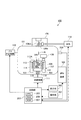
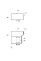
以下、本発明に係る第1の実施の形態について、図1乃至図8を用いて説明する。図1は本実施の形態に係る三次元造形装置の構成を示す説明図、図2は造形容器の構成を示す説明図である。また、図3は第1の実施の形態に係る切離し補助手段を示す模式図で、(a)は模式平面図、(b)は模式断面図である。また、図4は三次元造形物の造形工程を示すフローチャートである。また、図5は層形成時における造形容器を示す説明図で、(a)は本実施の形態の層形成時の説明図、(b)は変形例の層形成時の説明図である。また、図6は1層目のレーザービーム加熱形成時における造形容器を示す説明図で、図7は2層目のレーザービーム加熱形成時における造形容器を示す説明図である。そして、図8はテーブルの構成の変形例を示す模式図で、(a)はテーブルを二層構造で構成した場合の模式断面図、(b)はテーパ面を開口部の上端から設けた場合の模式断面図、(c)は開口部の垂直面を層より短くした場合の模式断面図である。
<First Embodiment>
[Schematic configuration of 3D modeling equipment]
Hereinafter, a first embodiment according to the present invention will be described with reference to FIGS. FIG. 1 is an explanatory diagram showing a configuration of a three-dimensional modeling apparatus according to the present embodiment, and FIG. 2 is an explanatory diagram showing a configuration of a modeling container. 3A and 3B are schematic views showing the separation assisting means according to the first embodiment, wherein FIG. 3A is a schematic plan view and FIG. 3B is a schematic cross-sectional view. Moreover, FIG. 4 is a flowchart which shows the modeling process of a three-dimensional structure. FIG. 5 is an explanatory view showing a modeling container at the time of layer formation, (a) is an explanatory view at the time of layer formation of the present embodiment, and (b) is an explanatory view at the time of layer formation of a modified example. FIG. 6 is an explanatory diagram showing the modeling container at the time of forming the first layer of laser beam heating, and FIG. 7 is an explanatory diagram showing the modeling container at the time of forming the second layer of laser beam by heating. FIG. 8 is a schematic view showing a modified example of the configuration of the table. (A) is a schematic cross-sectional view when the table is configured with a two-layer structure, and (b) is a case where a tapered surface is provided from the upper end of the opening. (C) is a schematic cross-sectional view when the vertical plane of the opening is made shorter than the layer.
まず、三次元造形装置100の概略構成を図1に用いて説明する。図1に示すように、三次元造形装置100は、金属製の原料紛体を粉末床溶融結合方式で三次元造形する、いわゆる3Dプリンタである。容器101は、例えばステンレス等の金属製で形成され、密閉可能である。容器101には、真空計208が接続されており、容器101内の圧力を検知可能に構成されている。排気機構103は、容器101内を減圧可能に構成されており、主に酸素を減少させるため、容器101内を排気する。また、排気機構103は、容器101との接続部に開口量を調整可能な開口調整弁を有する。制御部200は、後述のガス供給機構102によって容器101に気体を供給しつつ真空計208の出力に応じて開口調整弁を調整することで、容器101内を所望の雰囲気と真空度に制御することができる。
First, a schematic configuration of the three-
一方、ガス供給機構102は、例えば金属製の原料紛体を窒化処理する場合には窒素ガスと水素ガスの混合ガスを容器101内に供給する。ガス供給機構102は、窒素ガスと水素ガスを任意の混合割合で容器101内に供給可能である。なお、ガス供給機構を2箇所に設け、窒素ガスと水素ガスとを別々に供給するようにしてもよい。また、ガス供給機構102は、例えば金属製の原料紛体を炭化処理する場合にはアセチレンガスなどの単一ガスを容器101内に供給してもよいし、不活性ガスとアセチレンガスとを混合して供給してもよい。さらには、原料紛体の酸化をクリーニングする目的で水素ガスだけを供給するようにしてもよいし、水素ガスと不活性ガスとを混合して供給してもよい。
On the other hand, the
造形容器107は、造形室109の内側にステージの一例である造形ステージ112が昇降可能に配置されている。昇降機構111は、不図示のモータとこのモータにより回転駆動されるボールネジとを有しており、造形ステージ112を支持する支持軸115を上下方向に伸縮させることで造形ステージ112を昇降させる。これにより、昇降機構111は、後述する層形成機構105により形成される原料紛体の層の厚みに対応させた任意のピッチで造形ステージ112を段階的に下降させることができる。また、造形ステージ112と容器101の底面との間には、支持軸115の外周を覆う金属製のベローズ116が配置されている。このベローズ116は、造形ステージ112と容器101の底面とに対してシールされており、詳しくは後述するように原料紛体が造形ステージ112と側壁108との間から落下しても、原料紛体が容器101から漏れ出ないように構成されている。なお、容器101の底面に溜まった原料紛体は三次元造形を行っていないときなどに定期的に(例えば数週間〜数か月程度の期間で)清掃する。
In the
図1及び図2に示すように、造形容器107の造形室109を形成する側壁108は、造形ステージ112の昇降方向の外周に配置されている。側壁108には、加熱手段の一例であるヒータ114が埋め込まれて設けられており、薄い層300が積み重ねられて構成される積層305を加熱(予備加熱)可能となっている。なお、例えば造形ステージ112には不図示の温度センサが設けられており、制御部200は、温度センサの検出結果に基づいてヒータ114を制御することで積層305を所望の温度に管理する。また、ヒータ114は、例えば赤外線等により積層305を加熱できるもので、金属ヒータやカーボンヒータ等を用いる。
As shown in FIGS. 1 and 2, the
また、造形容器107の側壁108の上部には、造形ステージ112の上方を開口し、かつ側壁108よりも内側で上下方向に貫通して開口する開口部113Aを有するテーブル113が配置されている。即ち、テーブル113の開口部113Aの縁部は、造形室109を構成する側壁108よりも造形室109の内側方向に突出している。また、本実施の形態では、造形ステージ112の上面がテーブル113の上面と一致する位置まで上昇できるように、開口部113Aと造形ステージ112との水平方向の大きさが同じ、つまり水平方向の断面積が同じとなるように構成されている。このため、造形ステージ112は、開口部113Aが内側に突出している分だけ、側壁108との間に隙間120を有して離れていることになる。
Further, a table 113 having an
なお、造形ステージ112の側面の形状を詳しくは後述するテーブル113の開口部113Aの側面の形状と合わせて構成することで、造形ステージ112の水平方向の大きさを開口部113Aの大きさよりも大きくしてもよい。さらには、造形ステージ112と側壁108とを隙間なく接触するようにしてもよい。これらの場合、開口部113Aの縁部から落下した原料紛体が造形ステージ112の上面に溜まることが考えられるが、何らかの気体で吹き飛ばしたり、或いは吸引したりするようにしてもよい。このような気体の噴出口や吸引口は、造形ステージ112に内蔵させるようにすることが考えられる。
The shape of the side surface of the
一方、層形成手段の一例である層形成機構105は、テーブル113の上方を水平方向に移動可能に構成されており、開口部113Aを介して造形ステージ112の上に原料紛体の層300を形成する。原料粉体は、造形室109の水平方向の近傍に配置された不図示の原料室に蓄積されており、原料室の上方に押し出された一層分以上の原料紛体を層形成機構105で押遣って開口部113Aの中に一定厚さの原料粉体の層300を形成する。また、層形成機構105は、造形ステージ112の上に形成された層300を造形ステージ112が一層分降下させることで、次の層300を積層させる。なお、開口部113Aに入らずに余った原料紛体は、テーブル113の縁より外側に層形成機構105で押し出して落下させる。
On the other hand, the
ビーム照射手段の一例である走査加熱機構106は、層300にエネルギービームの一例であるレーザービームLBを照射する。走査加熱機構106は、光源110で発生させたレーザービームLBを透明な照射窓106eを介してガルバノミラー106mで走査することにより、層300における入力データに応じた固形化領域をレーザービームのスポットで加熱する。
A
走査加熱機構106は、造形容器107の造形室109の上面の層300を、レーザービームによって加熱し、ほぼ瞬時に溶融して下層の固体組織と一体に固形化させる。これにより、造形室109の上面の層300の所望の領域を溶融して固形化することができる。このとき、レーザービーム加熱成形処理中も積層305(特に三次元造形物301)の温度を、例えば造形していない粉体である非造形部分303において溶融を生じず、かつなるべく溶融する温度に近い温度にすることが望ましい。即ち、例えば原料紛体がSUS316であれば、1370〜1400°C以下でなるべく高い温度が望ましい。このため、本実施の形態では、上述のように隙間120を設けることで、積層305と側壁108とが原料紛体の拡散接合で固着してしまう虞がないので、積層305の温度を原料紛体が拡散接合を生じる温度以上(例えば600°C以上)に維持する。積層305の温度を高く保つことで、三次元造形物301の溶融状態のばらつきを減らすと共に溶融部分と溶融後(造形後)の部分との温度差を低減し、高精度の三次元造形物301を造形することが可能となる。なお、積層305における非造形部分303では、原料紛体が拡散接合することになるが、三次元造形が終了した後、非造形部分303を削ったり崩したりすることで、三次元造形物301を所望の形状で得ることができる。
The
制御部200は、CPU205、RAM206、及びROM207を有している。ROM207から呼び出したプロセスの制御プログラムをRAM206に保持することで、CPU205は、三次元造形のプロセスコントローラとして機能する。ユーザーは、表示部202に表示される各種の情報を視認しながら、操作部201を介して三次元造形装置100を操作する。また、制御部200は、上述した光源110、走査加熱機構106、ガス供給機構102、排気機構103、層形成機構105、及び昇降機構111を制御し、三次元造形のプロセスを実行する。
The
[テーブルの開口部の形状]
次に、本第1の実施の形態に係る切離し補助手段としてのテーブル113の開口部113Aの形状について図3に用いて説明する。なお、図3(a)に示す模式平面図及び図3(b)に示す模式断面図は、テーブル113の一部を切取って示したもので、テーブル113の全体像は貫通して形成された孔が上方視で矩形状(例えば正方形)の開口部113Aとして視認できる板状の部材である。
[Table opening shape]
Next, the shape of the
図3(b)に示すように、テーブル113の開口部113Aは、上方部分が垂直方向に形成された垂直部113Aaと下方側に向けて水平方向の断面積が大きくなる傾斜面であるテーパ形状のテーパ部113Abとを有する形状で構成されている。垂直部113Aaの厚みは、層300(図2参照)の厚みと同じか、それ以上の厚みに形成されている。これにより層300が形成された際に垂直部113Aaが層300の側面を覆い、原料紛体が落下し難くなる。また、図3(a)及び図3(b)に示すように、垂直部113Aaは、山部113aと谷部113bとの形成方向が垂直方向に並んでいる、いわゆる鋸形状の凹凸形状に形成されている。このように形成することで、垂直部113Aaを平面状に形成する場合に比して、詳しくは後述する開口部113Aに隣接して形成される造形壁302に隣接する部分の面積を減らすことができる。即ち、造形壁302と垂直部113Aaとは、僅かな隙間を存して対向し、特に山部113aが造形壁302に隣接(或いは近接)している状態となる。しかしながら、谷部113bが山部113aに比して造形壁302から遠ざかることになるので、上記隣接する部分の面積としては低減されている。さらに、造形壁302を溶融する際に、熱量が山部113aに流入することになるが、谷部113bに向けて熱が拡散する。このため、テーブル113の開口部113Aの全体としての温度上昇が小さくなる。これにより、造形壁302と開口部113Aとの間の僅かな隙間にある原料紛体の温度上昇が抑えられ、拡散接合が生じ難くなる。
As shown in FIG. 3 (b), the
なお、垂直部113Aaの山部113aと谷部113bとの形成方向は、垂直方向に限らず、水平方向であっても、垂直方向に対して傾斜した方向であっても上記造形壁302に隣接する部分の面積を減じる目的ではどのような方向でもよい。しかしながら、造形壁302を形成した際に溶融されなかった原料紛体が谷部113bに存在する可能性がある。このとき、山部113aと谷部113bとの形成方向が垂直方向或いはそれに近い方向であると、谷部113bにある原料紛体が下方に落下し易くなり、谷部113bに溜まり難くなるので望ましい。また、テーブル113の開口部113Aのうちの下方側にあるテーパ部113Abは、下方側に向けて広がっていることになるので、原料紛体の落下を妨げず、つまり開口部113Aに原料紛体が溜まることを防止している。
In addition, the formation direction of the
[三次元造形の工程]
図4に示すように、制御部200は、プロセス開始を指令されると、排気機構103を作動させて容器101内を排気する。続いて、容器101内の圧力が例えば1×10⁻²Paに達すると、ガス供給機構102による気体供給を開始して窒素ガスと水素ガスの混合気体の供給を開始する。そして、容器101内の圧力を大気圧未満のプロセス圧力(例えば10kPa)に調整し、三次元造形を行うための雰囲気を調整する(雰囲気調整工程)(S11)。
[Three-dimensional modeling process]
As shown in FIG. 4, when instructed to start the process, the
次に制御部200は、ヒータ114をオンし、造形室109の予備加熱を開始する(予備加熱開始工程)(S12)。なお、制御部200は、造形ステージ112に配置された不図示の温度センサが検出した温度に応じて、この後に層300が積み重ねられて構成される積層305が溶融を生じない温度になるようヒータ114を制御する。
Next, the
続けて制御部200は、昇降機構111を作動させて造形ステージ112を下降させ、造形ステージ112の上にあってテーブル113の開口部113Aに囲まれた領域に、層300の形成余地を形成する。そして、図5(a)に示すように、層形成機構105を作動させて原料粉体の層300を形成する(層形成工程)(S13)。この際、ヒータ114により層300が加熱されることで、容器101内にある水素が金属製の原料紛体の表面を脱酸素してクリーニングし、窒素により原料紛体の窒化が進む。
Subsequently, the
なお、図5(b)に示す変形例のように、原料紛体の層300を形成する際、テーブル113の上に例えば1mm程度の原料紛体の層を形成しておいてもよい。即ち、層形成機構105が層を形成する平面方向と造形ステージ112の平面方向との平行度が僅かにずれている場合、層300の平行度や平面度の精度が良好でなくなる虞がある。そのため、層形成機構105により造形ステージ112及びテーブル113の上に例えば1mm程度の原料紛体の層を形成しておくと、その層の上面の平行度や平面度は、層形成機構105の平面方向に倣って合わせられる。これにより、特に2層目以降は、その上に層が形成されることになり、形成される層300の平行度や平面度を高精度にすることができる。また、その後にレーザービームLBにより造形が行われる層300が、テーブル113の開口部113Aから例えば1mm分の距離で離れる。このため、開口部113Aに造形による熱量が流入し難くなり、開口部113Aと造形壁302との拡散接合の防止を図ることができる。
5B, when the raw
次に制御部200は、走査加熱機構106及び光源110を作動させて、層300のレーザービーム加熱成形処理を実行する(S14)。このレーザービーム成形処理(造形工程)では、走査加熱機構106及び光源110を作動させて、図6に示すように、造形ステージ112上の層300の原料紛体における所望の固形化領域にレーザービームLBを照射して溶融し、その部分を固形化する。この際、制御部200は、固形化領域として、三次元造形物301を造形する領域と、テーブル113の開口部113Aの内側に隣接して造形壁302を造形する領域とにレーザービームLBを照射する。つまり、1つの層300に対するレーザービーム成形処理の内で、三次元造形物301の1層分と造形壁302の1層分とを溶融して固形化する。
Next, the
また、造形壁302はテーブル113の開口部113Aの内側に隣接して造形されるので、テーブル113の開口部113Aと造形壁302との間には僅かな隙間を存するだけで造形壁302が造形される。このため、次の層300が形成される際に、テーブル113の開口部113Aと造形壁302との間から原料紛体が落下し難くなる。さらに、造形壁302と造形容器107の側壁108との間は、隙間120によって離間している。このため、ヒータ114により層300(積層305)を、拡散接合が生じる温度で予備加熱しても、造形壁302と造形容器107の側壁108とが固着することはない。
In addition, since the
次に、図4に示すように、制御部200は、層300の1層分のレーザービーム加熱成形処理が終了すると、昇降機構111により造形ステージ112を1層分下降させる下降処理(下降工程)を実行する(S15)。この際、層300における造形壁302の領域が溶融され、その領域がテーブル113の開口部113Aに隣接しているので、造形壁302と開口部113Aとの間には原料紛体が存在している。しかしながら、上述したように開口部113Aの垂直部113Aaには、山部113aと谷部113bとが形成されて凹凸形状となっているので(図3参照)、開口部113Aと造形壁302との間の原料紛体の温度上昇が抑えられ、拡散接合し難くなっている。これにより、昇降機構111により造形ステージ112の下降処理を実行する際、造形壁302とテーブル113の開口部113Aとの切離しは、接触面積の減少により補助される。従って、造形ステージ112と造形壁302とが固着していても、造形ステージ112の下降処理の実行が不可能となることが防止される。なお、造形ステージ112には、造形プレートを設置し、その上に三次元造形物301や造形壁302を造形してもよい。この場合も造形プレートが造形ステージ112に固定されるので、造形壁302がテーブル113に固着すると造形ステージ112の下降処理の実行が不可能になる虞がある。しかしながら、本実施の形態では、造形壁302とテーブル113の開口部113Aとの切離しが補助されるので、造形ステージ112の下降処理が不可能となることが防止される。
Next, as shown in FIG. 4, when the laser beam thermoforming process for one layer of the
上記下降処理が終了すると、制御部200は、三次元造形物301の成形に必要な積層回数に達しているか否かを判定し(S16)、積層回数が終了していない場合には(S16のNo)、ステップS13に戻り、次の層形成に移行する。なお、このステップS13からステップS16までの処理を各層の造形処理とする。
When the descending process is completed, the
次の層形成が行われ、造形ステージ112の上に2層目の層が形成されると、ステップS14に進み、図7に示すように、2層目の層300のレーザービーム加熱成形処理を実行する。この2層目のレーザービーム加熱成形処理において、制御部200は、三次元造形物301を造形する領域では、三次元造形物301の形状に応じた領域にレーザービームLBを照射する。また、造形壁302を造形する領域では、1層目の層と同じ領域にレーザービームLBを照射する。そして、2層目のレーザービーム加熱成形処理が終了すると、上述のように開口部113Aの垂直部113Aaの形状により造形壁302杜の切離しが補助されつつ、昇降機構111により造形ステージ112を1層分下降させる(S15)。
When the next layer formation is performed and the second layer is formed on the
そして、以上のような層の積層を繰り返し、例えば数mm程度の積層が行われても、各層で造形壁302が形成されているため、造形壁302とテーブル113の開口部113Aとの間から原料紛体が落下し難い。その後、三次元造形物301の形成に必要な積層回数に達すると(S16のYes)、制御部200は、ヒータ114をオフして予備加熱を停止する(予備加熱停止工程)(S17)。そして、制御部200は、容器101内のガスを排出してから容器101内に外気を供給し(大気復帰工程)(S18)、表示部202を通じて三次元造形物301の取り出しを許可する。
Then, the above-described layer stacking is repeated, and for example, even if stacking of about several millimeters is performed, the
なお、以上の三次元造形の工程実行中に、造形壁302とテーブル113の開口部113Aとの間にあって、特に谷部113bにある原料紛体が落下することがある。しかし、図2に示すように造形ステージ112の断面方向の大きさは、テーブル113の開口部113Aとほぼ同じ大きさに形成されている。即ち、造形ステージ112と造形容器107の側壁108との間が、側壁108と造形壁302との間の隙間120と同じ距離で離れている。そのため、落下した原料紛体が造形ステージ112よりも下に落下するので、側壁108と造形ステージ112との間に挟まって、それらを固着してしまうことが防止されている。また、造形ステージ112よりも下に落下した原料紛体は、図1に示すように、容器101の底部分に溜まるが、ベローズ116によってシールされるので容器101から外部に漏れ出ることはない。容器101の底部分に溜まった原料紛体は、三次元造形の工程が終了した状態で定期的に清掃することで取り除かれる。
During execution of the above three-dimensional modeling process, the raw material powder in the
以上説明したように、三次元造形物301を形成する際に、側壁108よりも内側で開口するテーブル113の開口部113Aに隣接して造形壁302を形成するので、側壁108と造形壁302とを離すことができる。このため、側壁108に配置されたヒータ114で造形ステージ112の上の積層305を例えば溶融が生じる手前でかつ拡散接合が生じる温度に加熱しても、側壁108と積層305(即ち造形壁302)とが固着することを防止できる。これにより、造形ステージ112が昇降不能となってしまうことを防止することができ、かつ三次元造形物301を高精度に造形することを可能とすることができる。そして、第1の実施の形態では切離し補助手段としてテーブル113の開口部113Aの凹凸形状により、開口部113Aと造形壁302との切離しを補助する。このため、造形ステージ112を下降させる際に開口部113Aと造形壁302との切離しを容易にでき、開口部113Aと造形壁302との固着の防止を図ることができ、造形ステージ112が昇降不能となってしまうことを防止することができる。
As described above, when the three-
また、テーブル113の開口部113Aは、厚み方向の上方側より下方側が水平方向の断面積が大きくなる形状に形成されている。つまり開口部113Aは、その側面にあって、厚み方向の上部に垂直方向に向けて形成された垂直部113Aaと、厚み方向の下部に下方側に向けて水平方向の断面積が大きくなるテーパ部113Abとを有している。このため、造形壁302(或いは造形ステージ112)と開口部113Aとの接触面積が小さくなり、造形ステージ112を下降させる際の切離しが容易になると共に、それらの間から原料紛体が落下することを妨げないようにすることができる。
Further, the
また、造形ステージ112も、水平方向に対して側壁108との間に隙間120を存する大きさで構成されている。このため、ヒータ114で造形ステージ112の上の積層305を例えば溶融が生じる手前でかつ拡散接合が生じる温度に加熱しても、側壁108と造形ステージ112とが固着することを防止できる。
The
[テーブルの構成の変形例1]
ついで、テーブル113の構成を変更した変形例について図8に用いて説明する。変形例1として図8(a)にテーブル413の構成を示す。テーブル413は、いわゆる2層構造で構成したものであり、上方側に配置されて開口部413Aの上部を構成する薄板414と、薄板414の下方側に配置されて薄板414を支持すると共に開口部413Aの下部を構成する支持板415とを有している。支持板415の開口部415Aである開口部413Aの下部は、垂直方向から視て薄板414の開口部414Aである開口部413Aの上部の範囲に対して外側に位置している。つまり上方から視て薄板414の開口部414Aの方が狭く、支持板415の開口部415Aの方が外側に広がっている。言い換えると、開口部413Aの下部は、開口部413Aの上部より水平方向の断面積が大きいことになる。
[Table Configuration Modification 1]
Next, a modified example in which the configuration of the table 113 is changed will be described with reference to FIG. As a first modification, FIG. 8A shows the configuration of the table 413. The table 413 has a so-called two-layer structure. The table 413 is arranged on the upper side to form the upper portion of the
具体的に薄板414は、一枚の平板で構成され、上方から視て矩形状で貫通して形成された開口部414Aを有している。薄板414の厚みは、層300の1層分よりも薄い厚みで構成することで、造形壁302(造形ステージ112)に対して隣接する部分の面積を小さくでき、固着し難くすることができる。また、薄板414の開口部414Aの側面は、造形壁302(造形ステージ112)に対して隣接する部分の面積が小さいので平面状でも構わないが、上述した開口部113Aのように凹凸形状を形成しておいてもよい。
Specifically, the
一方の支持板415も、矩形状で貫通して形成された開口部415Aを有する一枚の平板で構成され、かつ薄板414よりも厚みが厚く構成されており、薄板414を下方から支持している。即ち、薄板414は厚みが薄いので撓み易いが、薄板414が支持板415によって下方から支持されることで平面度を維持するように構成されている。支持板415自体は、造形容器107の側壁108によって支持されている。支持板415の開口部415Aは、垂直方向に形成された垂直面415aと、下方側に向けて水平方向の断面積が大きくなるテーパ形状のテーパ面415bとを有している。垂直面415aは、薄板414の開口部414Aに近い方が薄板414の撓みを防止する補強機能として有効だが、近すぎると造形壁302(或いは造形ステージ112)に固着し易くなるので、薄板414の剛性に応じて適宜な距離に設定するとよい。また、支持板415がテーパ面415bを有していることで、原料紛体の落下を妨げないように構成されている。
One
このようにテーブル413を2層構造とすることで、薄板414を薄くでき、造形壁302(或いは造形ステージ112)に対向して配置される薄板414の開口部414Aの側面の面積を小さくすることができる。これにより、開口部414Aへの熱量の流入を小さくして温度上昇を抑えることができて、開口部414Aと造形壁302との間にある原料紛体の拡散接合を低減できる。このため、造形ステージ112の下降時におけるテーブル413の開口部413Aと造形壁302(或いは造形ステージ112)との切離しを補助することができる。また、薄板414よりも厚みの厚い支持板415によって薄板414を支持することで、薄板414の平面度を維持することができる。
Thus, by making the table 413 into a two-layer structure, the
[テーブルの構成の変形例2]
次に変形例2として図8(b)にテーブル513の構成を示す。テーブル513は、一枚の平板で構成され(1層構造で構成され)、貫通して形成された開口部513Aを有している。この開口部513Aは、下方側に向けて水平方向の断面積が大きくなるテーパ形状のテーパ面513aで構成されており、つまり垂直方向の垂直面を有していない構成となっている。このように開口部513Aを構成することで、造形壁302(或いは造形ステージ112)に対向する部分が鋭角形状となり、造形壁302(或いは造形ステージ112)に対して隣接する部分の面積を小さくできる。これにより、開口部513Aへの熱量の流入を小さくして温度上昇を抑えることができて、開口部513Aと造形壁302との間にある原料紛体の拡散接合を低減できる。このため、造形ステージ112の下降時におけるテーブル513の開口部513Aと造形壁302(或いは造形ステージ112)との切離しを補助することができる。また、テーブル513がテーパ面513aを有していることで、原料紛体の落下を妨げないように構成することができ、かつテーブル513の開口部513Aの付近の厚みが薄くなったとしても剛性が維持でき、テーブル513の平面度を維持することができる。
[Modification 2 of the table configuration]
Next, FIG. 8B shows a configuration of the table 513 as a second modification. The table 513 is configured by a single flat plate (configured by a one-layer structure), and has an
[テーブルの構成の変形例3]
次に変形例3として図8(c)にテーブル613の構成を示す。テーブル613は、図3に示すテーブル113と同様に、上方部分が垂直方向に形成された垂直部613Aaと下方側に向けて水平方向の断面積が大きくなる傾斜面であるテーパ形状のテーパ部613Abとを有する形状で構成されている。図3に示すテーブル113と異なり、垂直部613Aaの厚みを層300の1層分よりも薄い厚みで構成することで、造形壁302(造形ステージ112)に対して隣接する部分の面積を小さくできる。これにより、開口部613Aへの熱量の流入を小さくして温度上昇を抑えることができて、開口部613Aと造形壁302との間にある原料紛体の拡散接合を低減できる。このため、造形ステージ112の下降時におけるテーブル613の開口部613Aと造形壁302(或いは造形ステージ112)との切離しを補助することができる。また、テーブル613がテーパ部613Abを有していることで、原料紛体の落下を妨げないように構成することができ、かつテーブル613の開口部613Aの付近の厚みが薄くなったとしても剛性が維持でき、テーブル613の平面度を維持することができる。
[Modification 3 of the table configuration]
Next, FIG. 8C shows a configuration of the table 613 as a third modification. The table 613 includes a vertical portion 613Aa having an upper portion formed in a vertical direction and a tapered portion 613Ab having a tapered shape having an inclined surface with a horizontal cross-sectional area increasing toward the lower side, similarly to the table 113 shown in FIG. It is comprised by the shape which has. Unlike the table 113 shown in FIG. 3, the area of the portion adjacent to the modeling wall 302 (modeling stage 112) can be reduced by configuring the vertical portion 613Aa to be thinner than one layer of the
<第2の実施の形態>
ついで、第1の実施の形態を一部変更した第2の実施の形態について図9に用いて説明する。図9は第2の実施の形態に係る切離し補助手段を示す模式図で、(a)は模式平面図、(b)は模式断面図である。なお、図9(a)に示す模式平面図及び図9(b)に示す模式断面図も、テーブル213の一部を切取って示したもので、テーブル213の全体像は貫通して形成された孔が上方視で矩形状(例えば正方形)の開口部213Aとして視認できる板状の部材である。
<Second Embodiment>
Next, a second embodiment obtained by partially changing the first embodiment will be described with reference to FIG. 9A and 9B are schematic views showing a separation assisting means according to the second embodiment, wherein FIG. 9A is a schematic plan view and FIG. 9B is a schematic cross-sectional view. Note that the schematic plan view shown in FIG. 9A and the schematic cross-sectional view shown in FIG. 9B are also cut out of the table 213, and the entire image of the table 213 is formed through. The hole is a plate-like member that can be viewed as an
本第2の実施の形態は、造形ステージ112の下降時におけるテーブルと造形壁302(造形ステージ112)との切離しを補助する切離し補助手段として、テーブル213に冷却機能を追加したものである。具体的にテーブル213は、図9(a)及び図9(b)に示すように、第1の実施の形態のテーブル113と同様な構成の開口部213Aを有している。即ち、テーブル213の開口部213Aは、上方部分が垂直方向に形成された垂直部213Aaと下方側に向けて水平方向の断面積が大きくなる傾斜面であるテーパ形状のテーパ部213Abとを有する形状で構成されている。
In the second embodiment, a cooling function is added to the table 213 as a separation assisting means for assisting separation of the table and the modeling wall 302 (modeling stage 112) when the
そして、テーブル213は、内部に冷媒を循環させる循環路213aが冷却手段の一例として形成されており、循環路213aは、外部から開口部213Aの近傍まで周回して外部に戻る循環経路を構成している。循環路213aの供給側は、不図示の冷媒ポンプに接続されてテーブル213の外部から冷媒が供給される。また循環路213aの排出側は、熱交換器等の冷媒を冷却するクーラントに接続されている。従って、循環路213aを流れる冷媒は、循環路213aに供給され、開口部213Aの近傍を通ってクーラントに送られた後、再度冷媒ポンプに還流される。なお、図9(a)及び図9(b)では、1つの循環路213aを示しているが、テーブル213全体には、複数の循環路213aが並設されて、開口部213Aをなるべく均一に冷却するように構成されている。また、冷媒としては、例えば水、油などの液体を用いることが現実的である。さらに、テーブル213を冷却する手法としては、テーブル213を金属製で構成し、ペルチェ素子などを用いて冷却することも可能である。要するに、テーブル213、特に開口部213Aを冷却できれば、どのような構成でもよい。
In the table 213, a
このようにテーブル213を冷却することで開口部213Aの温度上昇を抑えられる。このため、ヒータ114で積層305を高温で予備加熱した状態で、造形壁302(造形ステージ112)との間にある原料紛体の温度上昇を抑えることができるので拡散接合が生じることを低減できる。これにより、造形ステージ112の下降時においてテーブル213の開口部213Aと造形壁302(造形ステージ112)との切離しを補助することができる。このため、造形ステージ112を下降させる際に開口部213Aと造形壁302との切離しを容易にでき、開口部213Aと造形壁302との固着の防止を図ることができ、造形ステージ112が昇降不能となってしまうことを防止することができる。
Thus, by cooling the table 213, the temperature rise of the
なお、これ以外の第2の実施の形態における構成、作用、効果は、第1の実施の形態と同様であるので、その説明を省略する。 Other configurations, operations, and effects in the second embodiment are the same as those in the first embodiment, and a description thereof will be omitted.
<第3の実施の形態>
ついで、第1の実施の形態を一部変更した第3の実施の形態について図10に用いて説明する。図10は第3の実施の形態に係る切離し補助手段を示す模式図で、(a)は模式平面図、(b)は模式断面図である。なお、図10(a)に示す模式平面図及び図10(b)に示す模式断面図において、テーブル113及び側壁108の一部を切取って示しているが、これらは第1の実施の形態と同様な構成である。
<Third Embodiment>
Next, a third embodiment obtained by partially changing the first embodiment will be described with reference to FIG. FIGS. 10A and 10B are schematic views showing the separation assisting means according to the third embodiment. FIG. 10A is a schematic plan view, and FIG. 10B is a schematic cross-sectional view. In the schematic plan view shown in FIG. 10A and the schematic cross-sectional view shown in FIG. 10B, the table 113 and a part of the
本第3の実施の形態は、造形ステージ112の下降時におけるテーブル113と造形壁302(造形ステージ112)との切離しを補助する切離し補助手段の一例としてガス供給機構102(図1参照)を造形容器107の底部分に接続して構成したものである。そして、気体を開口部113Aと造形壁302との間に流すように供給するものである。具体的には、造形容器107の底部分に気体を噴き出して供給する供給口(不図示)を設け、造形容器107の側壁108と造形ステージ112との間の隙間120を通過させて、矢印Wで示すように開口部113Aと造形壁302との間に供給する。この気体は、例えばアルゴンなどの不活性ガスであってもよいが、例えば原料紛体を窒化処理する場合には、水素ガスや窒素ガス或いはそれらの混合気体などを供給しても良いし、例えば原料紛体を炭化処理する場合には、アセチレンガスなどを供給しても良い。不活性ガスを供給する場合には、ガス供給機構102とは別の気体供給機構を設けてもよい。さらに、ガス供給機構102は、例えばベローズ116の内部を通して造形ステージ112に接続し、造形ステージ112の側面或いは下面から吹き出すようにしてもよい。
In the third embodiment, the gas supply mechanism 102 (see FIG. 1) is modeled as an example of a separation assisting unit that assists in separation of the table 113 and the modeling wall 302 (modeling stage 112) when the
このように気体を供給することで、テーブル113の開口部113Aと造形壁302との間にある原料紛体を吹き飛ばして清掃でき、かつ開口部113Aを冷却することもできるので、拡散接合を防止できる。これにより、造形ステージ112の下降時においてテーブル113の開口部113Aと造形壁302(造形ステージ112)との切離しを補助することができる。このため、造形ステージ112を下降させる際に開口部113Aと造形壁302との切離しを容易にでき、開口部113Aと造形壁302との固着の防止を図ることができ、造形ステージ112が昇降不能となってしまうことを防止することができる。
By supplying the gas in this way, the raw material powder between the
なお、これ以外の第3の実施の形態における構成、作用、効果は、第1の実施の形態と同様であるので、その説明を省略する。 In addition, since the structure, the effect | action, and effect in 3rd Embodiment other than this are the same as that of 1st Embodiment, the description is abbreviate | omitted.
<その他の実施の形態の可能性>
なお、以上説明した第1乃至第3の実施の形態においては、原料紛体として金属粉体を用いることを前提として説明したが、原料紛体は樹脂やセラミックなどであってもよく、どのような原料紛体であっても構わない。
<Possibility of other embodiments>
In the first to third embodiments described above, the description has been made on the assumption that metal powder is used as the raw material powder. However, the raw material powder may be resin, ceramic, etc. It may be a powder.
また、以上説明した第1の実施の形態では切離し補助手段として開口部の形状を、第2の実施の形態では切離し補助手段として冷却手段を、第3の実施の形態では切離し補助手段として気体供給手段を説明したが、これらは自在に組合せて用いることができる。 Further, in the first embodiment described above, the shape of the opening is used as the separation assisting means, the cooling means is used as the separation assisting means in the second embodiment, and the gas is supplied as the separation assisting means in the third embodiment. Although the means have been described, these can be used in any combination.
100…三次元造形装置:102…切離し補助手段、気体供給手段(ガス供給機構):105…層形成手段(層形成機構):106…ビーム照射手段(走査加熱機構):108…側壁:112…ステージ(造形ステージ):113…テーブル:113A…開口部:113Aa…垂直部:113Ab…テーパ部:113a,113b…切離し補助手段、凹凸形状(山部、谷部):114…加熱手段(ヒータ):200…制御部:213…テーブル:213A…開口部:213Aa…垂直部:213Ab…テーパ部:213a…切離し補助手段、冷却手段(循環路):300…層:301…三次元造形物:302…造形壁:413…テーブル:413A…開口部:414…薄板:415…支持板:513…テーブル:513A…開口部:613…テーブル:613A…開口部:613Aa…垂直部:613Ab…テーパ部:LB…エネルギービーム(レーザービーム)
DESCRIPTION OF
Claims (11)
昇降可能に構成され、前記層が積層されるステージと、
前記ステージに形成された層にエネルギービームを照射するビーム照射手段と、
前記ステージの昇降方向の外周に配置される側壁と、
前記側壁に配置され、前記ステージの上の積層を加熱する加熱手段と、
前記ステージの上方に配置され、前記側壁よりも内側で開口して前記層形成手段により層が形成される開口部を有するテーブルと、
前記層を形成し、前記ステージの上の層にエネルギービームを照射して三次元造形物を形成すると共に前記開口部の内側に隣接して造形壁を形成して、前記層の厚み分について前記ステージを下降させる各層の造形処理を繰り返し実行するように、前記層形成手段、前記ビーム照射手段、及び前記ステージを制御する制御部と、
前記ステージが下降するに際して、前記開口部と前記造形壁との切離しを補助する切離し補助手段と、を備える、
ことを特徴とする三次元造形装置。 Layer forming means for forming a layer of raw material powder;
A stage configured to be movable up and down, on which the layers are stacked;
Beam irradiation means for irradiating an energy beam to the layer formed on the stage;
A side wall disposed on the outer periphery of the stage in the up-and-down direction;
A heating means disposed on the side wall for heating the stack on the stage;
A table that is disposed above the stage and has an opening that is opened inside the side wall and in which a layer is formed by the layer forming means;
Forming the layer, irradiating the layer above the stage with an energy beam to form a three-dimensional structure, forming a modeling wall adjacent to the inside of the opening, and about the thickness of the layer The layer forming means, the beam irradiation means, and a control unit for controlling the stage so as to repeatedly execute the modeling process of each layer for lowering the stage;
A separation assisting means for assisting separation of the opening and the modeling wall when the stage is lowered,
A three-dimensional modeling apparatus characterized by this.
ことを特徴とする請求項1に記載の三次元造形装置。 The separation assisting means is an uneven shape formed on the inner side surface of the opening of the table.
The three-dimensional modeling apparatus according to claim 1.
ことを特徴とする請求項1又は2に記載の三次元造形装置。 The separation assisting means is a cooling means for cooling the opening of the table.
The three-dimensional modeling apparatus according to claim 1 or 2, characterized in that
ことを特徴とする請求項1乃至3のいずれか1項に記載の三次元造形装置。 The separation assisting means is a gas supply means for supplying and passing a gas between the opening and the modeling wall.
The three-dimensional modeling apparatus according to any one of claims 1 to 3, wherein:
ことを特徴とする請求項1乃至4のいずれか1項に記載の三次元造形装置。 The opening of the table is formed in a shape in which the cross-sectional area in the horizontal direction is larger than the upper side in the thickness direction.
The three-dimensional modeling apparatus according to any one of claims 1 to 4, wherein the three-dimensional modeling apparatus is characterized.
ことを特徴とする請求項5に記載の三次元造形装置。 The opening portion of the table is on a side surface thereof, and a vertical portion formed in a vertical direction at an upper portion in the thickness direction and a tapered portion in which a cross-sectional area in a horizontal direction increases toward a lower side in a lower portion in the thickness direction. And having
The three-dimensional modeling apparatus according to claim 5.
ことを特徴とする請求項6に記載の三次元造形装置。 The vertical portion is thinner than the layer by the layer forming means,
The three-dimensional modeling apparatus according to claim 6.
ことを特徴とする請求項5に記載の三次元造形装置。 The table includes a thin plate disposed on the upper side and constituting the upper portion of the opening, and a support plate disposed on the lower side of the thin plate and supporting the thin plate and constituting the lower portion of the opening. The lower part of the opening is located outside the upper part of the opening as viewed from the vertical direction and has a larger cross-sectional area in the horizontal direction than the upper part of the opening.
The three-dimensional modeling apparatus according to claim 5.
ことを特徴とする請求項5に記載の三次元造形装置。 The opening of the table is formed in a tapered shape in which the entire side surface has a cross-sectional area that increases toward the lower side in the thickness direction.
The three-dimensional modeling apparatus according to claim 5.
ことを特徴とする請求項1乃至9のいずれか1項に記載の三次元造形装置。 The stage is configured to have a gap between the side wall and the horizontal direction,
The three-dimensional modeling apparatus according to any one of claims 1 to 9, wherein the three-dimensional modeling apparatus is characterized.
前記ステージに形成された層にエネルギービームを照射して三次元造形物を形成すると共に前記開口部の内側に隣接して造形壁を形成する造形工程と、
切離し補助手段により前記開口部と前記造形壁との切離しを補助しながら、前記ステージを前記層の厚みに合わせて下降させる下降工程と、を備え、
前記各工程を繰り返し実行することにより三次元造形物を造形する、
ことを特徴とする三次元造形方法。 A layer of raw material powder is formed on the stage through a side wall having heating means arranged on the outer periphery of the stage that can be raised and lowered to heat the stack on the stage, and an opening in the table that opens on the inner side. A layer forming step to perform,
A modeling step of forming a three-dimensional structure by irradiating an energy beam to the layer formed on the stage and forming a modeling wall adjacent to the inside of the opening;
A lowering step of lowering the stage according to the thickness of the layer while assisting the separation of the opening and the modeling wall by a separation assisting means,
Modeling a three-dimensional structure by repeatedly executing each of the steps,
A three-dimensional modeling method characterized by this.
Priority Applications (1)
| Application Number | Priority Date | Filing Date | Title |
|---|---|---|---|
| JP2016029283A JP2017145476A (en) | 2016-02-18 | 2016-02-18 | Three-dimensional molding apparatus and three-dimensional molding method |
Applications Claiming Priority (1)
| Application Number | Priority Date | Filing Date | Title |
|---|---|---|---|
| JP2016029283A JP2017145476A (en) | 2016-02-18 | 2016-02-18 | Three-dimensional molding apparatus and three-dimensional molding method |
Publications (1)
| Publication Number | Publication Date |
|---|---|
| JP2017145476A true JP2017145476A (en) | 2017-08-24 |
Family
ID=59682106
Family Applications (1)
| Application Number | Title | Priority Date | Filing Date |
|---|---|---|---|
| JP2016029283A Pending JP2017145476A (en) | 2016-02-18 | 2016-02-18 | Three-dimensional molding apparatus and three-dimensional molding method |
Country Status (1)
| Country | Link |
|---|---|
| JP (1) | JP2017145476A (en) |
Cited By (6)
| Publication number | Priority date | Publication date | Assignee | Title |
|---|---|---|---|---|
| JP2019073795A (en) * | 2017-10-13 | 2019-05-16 | ツェーエル・シュッツレヒツフェアヴァルトゥングス・ゲゼルシャフト・ミト・べシュレンクテル・ハフツング | Plant for additively manufacturing three-dimensional object |
| JP2019081937A (en) * | 2017-10-31 | 2019-05-30 | 株式会社Ihi | Powder saving device and powder saving method |
| WO2019166379A1 (en) * | 2018-02-27 | 2019-09-06 | Arcam Ab | A compact build tank for an additive manufacturing apparatus |
| WO2021003202A3 (en) * | 2019-07-02 | 2021-03-11 | Nikon Corporation | Non-coaxial rotating turntables for additive manufacturing |
| WO2022030042A1 (en) * | 2020-08-03 | 2022-02-10 | 株式会社日立製作所 | Additive manufacturing method |
| US12303975B2 (en) | 2021-09-16 | 2025-05-20 | Nikon Corporation | Analyzer system for aligning and focusing an energy beam in a three-dimensional printer |
-
2016
- 2016-02-18 JP JP2016029283A patent/JP2017145476A/en active Pending
Cited By (11)
| Publication number | Priority date | Publication date | Assignee | Title |
|---|---|---|---|---|
| JP2019073795A (en) * | 2017-10-13 | 2019-05-16 | ツェーエル・シュッツレヒツフェアヴァルトゥングス・ゲゼルシャフト・ミト・べシュレンクテル・ハフツング | Plant for additively manufacturing three-dimensional object |
| JP2019081937A (en) * | 2017-10-31 | 2019-05-30 | 株式会社Ihi | Powder saving device and powder saving method |
| WO2019166379A1 (en) * | 2018-02-27 | 2019-09-06 | Arcam Ab | A compact build tank for an additive manufacturing apparatus |
| CN111801185A (en) * | 2018-02-27 | 2020-10-20 | 阿尔卡姆公司 | A compact build box for additive manufacturing equipment |
| US11458682B2 (en) | 2018-02-27 | 2022-10-04 | Arcam Ab | Compact build tank for an additive manufacturing apparatus |
| WO2021003202A3 (en) * | 2019-07-02 | 2021-03-11 | Nikon Corporation | Non-coaxial rotating turntables for additive manufacturing |
| WO2022030042A1 (en) * | 2020-08-03 | 2022-02-10 | 株式会社日立製作所 | Additive manufacturing method |
| JP2022028322A (en) * | 2020-08-03 | 2022-02-16 | 株式会社日立製作所 | Additive manufacturing method |
| JP7394032B2 (en) | 2020-08-03 | 2023-12-07 | 株式会社日立製作所 | additive manufacturing methods |
| US12459038B2 (en) | 2020-08-03 | 2025-11-04 | Hitachi, Ltd. | Additive manufacturing method |
| US12303975B2 (en) | 2021-09-16 | 2025-05-20 | Nikon Corporation | Analyzer system for aligning and focusing an energy beam in a three-dimensional printer |
Similar Documents
| Publication | Publication Date | Title |
|---|---|---|
| JP2017145476A (en) | Three-dimensional molding apparatus and three-dimensional molding method | |
| US7351051B2 (en) | Powder sinter layered manufacturing apparatus | |
| CN102438779B (en) | Layered-modeling device and method using said device for manufacturing three-dimensional objects | |
| US10029308B2 (en) | Three dimensional printer | |
| KR102151445B1 (en) | Additive manufacturing apparatus and method for manufacturing three dimensional object | |
| JP5355213B2 (en) | Laminate modeling equipment for modeling three-dimensional shaped objects | |
| JP4693681B2 (en) | Manufacturing method of stereolithography | |
| JP6483551B2 (en) | Powder bed fusion unit | |
| US20160107229A1 (en) | Three dimensional printer | |
| JP5893112B1 (en) | Additive manufacturing equipment | |
| CN105142827A (en) | Build plate and apparatus for additive manufacturing | |
| US20160107232A1 (en) | Three dimensional printer | |
| JP6643643B2 (en) | Manufacturing method of three-dimensional shaped object | |
| JP2019516580A (en) | Additive manufacturing machine with pick-up system and method of additive manufacturing using such machine | |
| JP6157002B2 (en) | Molten layer laminated structure manufacturing apparatus, molten layer laminated structure manufacturing method, and molten layer laminated structure | |
| US20240091852A1 (en) | Method for producing three-dimensional molded object | |
| JP6653590B2 (en) | Cooling optimization device and cooling optimization method | |
| CN106903878A (en) | Three-dimensional moulding device and 3-dimensional object formation | |
| JP6939423B2 (en) | Powder saving device and powder saving method | |
| GB2515287A (en) | An Additive Layer Manufacturing Method | |
| WO2019159635A1 (en) | Additive manufacturing device | |
| JP2020012145A (en) | Method for manufacturing three-dimensional molded article | |
| CN109249023B (en) | A scratch-resistant 3D printing method and a 3D printing system | |
| JP2019196523A (en) | Apparatus and method for lamination molding | |
| JP2019001088A (en) | Laminate molding apparatus and laminate molding system |