JP2017055540A - Wire harness - Google Patents
Wire harness Download PDFInfo
- Publication number
- JP2017055540A JP2017055540A JP2015177229A JP2015177229A JP2017055540A JP 2017055540 A JP2017055540 A JP 2017055540A JP 2015177229 A JP2015177229 A JP 2015177229A JP 2015177229 A JP2015177229 A JP 2015177229A JP 2017055540 A JP2017055540 A JP 2017055540A
- Authority
- JP
- Japan
- Prior art keywords
- wire harness
- conductive path
- exterior member
- linear
- vibration
- Prior art date
- Legal status (The legal status is an assumption and is not a legal conclusion. Google has not performed a legal analysis and makes no representation as to the accuracy of the status listed.)
- Granted
Links
Images


Classifications
-
- B—PERFORMING OPERATIONS; TRANSPORTING
- B60—VEHICLES IN GENERAL
- B60R—VEHICLES, VEHICLE FITTINGS, OR VEHICLE PARTS, NOT OTHERWISE PROVIDED FOR
- B60R16/00—Electric or fluid circuits specially adapted for vehicles and not otherwise provided for; Arrangement of elements of electric or fluid circuits specially adapted for vehicles and not otherwise provided for
- B60R16/02—Electric or fluid circuits specially adapted for vehicles and not otherwise provided for; Arrangement of elements of electric or fluid circuits specially adapted for vehicles and not otherwise provided for electric constitutive elements
- B60R16/0207—Wire harnesses
- B60R16/0215—Protecting, fastening and routing means therefor
-
- H—ELECTRICITY
- H02—GENERATION; CONVERSION OR DISTRIBUTION OF ELECTRIC POWER
- H02G—INSTALLATION OF ELECTRIC CABLES OR LINES, OR OF COMBINED OPTICAL AND ELECTRIC CABLES OR LINES
- H02G3/00—Installations of electric cables or lines or protective tubing therefor in or on buildings, equivalent structures or vehicles
- H02G3/02—Details
- H02G3/04—Protective tubing or conduits, e.g. cable ladders or cable troughs
- H02G3/0462—Tubings, i.e. having a closed section
- H02G3/0481—Tubings, i.e. having a closed section with a circular cross-section
Landscapes
- Engineering & Computer Science (AREA)
- Mechanical Engineering (AREA)
- Architecture (AREA)
- Civil Engineering (AREA)
- Structural Engineering (AREA)
- Details Of Indoor Wiring (AREA)
- Insulated Conductors (AREA)
Abstract
【課題】外装部材内での導電路の振れを抑制することが可能なワイヤハーネスを提供する。【解決手段】ワイヤハーネス15は、管体形状の外装部材21と、この外装部材21に挿通・保護される導電路22と、導電路22と一緒に外装部材21に挿通される線状の振動抑制線状部材23とを備えて構成される。振動抑制線状部材23は、外装部材21の少なくとも内部所定範囲での導電路22の遊び率を減らして振れを抑制するための部材として備えられる。具体的には、弾力性を有するチューブが振動抑制線状部材23として好適であり、このような振動抑制線状部材23を備えることによって導電路22は外装部材21との相対的な振れが抑制される。【選択図】図2A wire harness capable of suppressing a swing of a conductive path in an exterior member is provided. A wire harness includes a tubular outer member, a conductive path inserted and protected by the outer member, and a linear vibration inserted into the outer member together with the conductive path. And a restraining linear member 23. The vibration suppression linear member 23 is provided as a member for reducing the play rate of the conductive path 22 in at least a predetermined range of the exterior member 21 and suppressing the deflection. Specifically, a tube having elasticity is suitable as the vibration suppressing linear member 23, and by providing such a vibration suppressing linear member 23, the conductive path 22 suppresses relative shake with the exterior member 21. Is done. [Selection] Figure 2
Description
本発明は、管体形状の外装部材と、この外装部材に挿通・保護される一又は複数本の導電路とを備えるワイヤハーネスに関する。 The present invention relates to a wire harness including a tubular-shaped exterior member and one or a plurality of conductive paths inserted and protected by the exterior member.
自動車に搭載される機器間を電気的に接続するためにワイヤハーネスが用いられる。ワイヤハーネスは、管体形状の外装部材と、この外装部材に収容される一又は複数本の導電路とを備えて構成される。例えば下記特許文献1のワイヤハーネスにあっては、自動車の車両床下を通るように配索される。ワイヤハーネスは、車両床下に対応する部分がストレートに配索される。このようなワイヤハーネスは、長尺に形成される。尚、下記特許文献1では、特にストレートに配索される部分に関し次のようなことが分かる。すなわち、外装部材内の導電路が走行中の振動等により振れてしまうということが分かる。
A wire harness is used to electrically connect devices mounted on an automobile. The wire harness includes a tubular-shaped exterior member and one or a plurality of conductive paths accommodated in the exterior member. For example, the wire harness disclosed in
上記従来技術にあっては、外装部材内の導電路が走行中の振動により大きく振れてしまうと、導電路の被覆が(シールド機能を有する場合、導電路外側の編組や金属箔が)外装部材の管内面に強く当たって損傷してしまうという問題点を有する。 In the above prior art, when the conductive path in the exterior member is greatly shaken by vibration during traveling, the coating of the conductive path (if the shield function is provided, the braid or metal foil outside the conductive path) is the exterior member. There is a problem that the inner surface of the tube is strongly hit and damaged.
本発明は、上記した事情に鑑みてなされたもので、外装部材内での導電路の振れを抑制することが可能なワイヤハーネスを提供することを課題とする。 This invention is made | formed in view of an above-described situation, and makes it a subject to provide the wire harness which can suppress the fluctuation | variation of the conductive path in an exterior member.
上記課題を解決するためになされた請求項1に記載の本発明のワイヤハーネスは、管体形状の外装部材と、該外装部材に挿通・保護される一又は複数本の導電路とを備えるワイヤハーネスにおいて、当該ワイヤハーネスは、前記外装部材の少なくとも内部所定範囲での前記導電路の遊び率を減らして振れを抑制する線状の振動抑制線状部材を更に備えることを特徴とする。
The wire harness of the present invention according to
このような特徴を有する本発明によれば、振動抑制線状部材を更に備えることにより、外装部材の内部所定範囲での導電路の遊び率を振動抑制線状部材の存在にて減らすことができる。そして、その範囲での振れ幅を小さくしたりすることができる。従って、振れ易い箇所であっても、導電路と外装部材との相対的な振れを抑制することができる。 According to the present invention having such a feature, the play rate of the conductive path in the predetermined range inside the exterior member can be reduced by the presence of the vibration suppression linear member by further including the vibration suppression linear member. . And the runout width in that range can be reduced. Therefore, even if it is a location where it is easy to shake, relative shake between the conductive path and the exterior member can be suppressed.
請求項2に記載の本発明は、請求項1に記載のワイヤハーネスにおいて、前記振動抑制線状部材は、前記導電路と一緒に前記外装部材に挿通され、且つ、弾力性を有するチューブであることを特徴とする。 According to a second aspect of the present invention, in the wire harness according to the first aspect, the vibration suppressing linear member is a tube that is inserted into the exterior member together with the conductive path and has elasticity. It is characterized by that.
このような特徴を有する本発明によれば、外装部材の内部所定範囲にチューブが振動抑制線状部材として導電路と一緒に挿通されることから、チューブの弾力性にて導電路と外装部材との相対的な振れを抑制することができる。 According to the present invention having such a feature, since the tube is inserted into the predetermined range inside the exterior member together with the conductive path as a vibration suppressing linear member, the conductive path and the exterior member are made elastic by the tube. The relative shake of can be suppressed.
請求項3に記載の本発明は、請求項1又は2に記載のワイヤハーネスにおいて、前記内部所定範囲は、少なくとも当該ワイヤハーネスをストレートに配索する部分を対象にして設定されることを特徴とする。 According to a third aspect of the present invention, in the wire harness according to the first or second aspect, the predetermined internal range is set for at least a portion in which the wire harness is routed straight. To do.
このような特徴を有する本発明によれば、ワイヤハーネスをストレートに配索する部分が導電路の振れ易い箇所になり、このストレートに配索する部分を対象に振動抑制線状部材が外装部材に配設される。従って、振れ易い箇所であっても、導電路と外装部材との相対的な振れを抑制することができる。 According to the present invention having such characteristics, the portion where the wire harness is routed straight becomes a portion where the conductive path is likely to be shaken, and the vibration suppressing linear member is used as the exterior member for the portion routed straight. Arranged. Therefore, even if it is a location where it is easy to shake, relative shake between the conductive path and the exterior member can be suppressed.
請求項1に記載された本発明によれば、振動抑制線状部材を更に備えることから、例えば走行中であっても外装部材内での導電路の振れを振動抑制線状部材にて抑制することができるという効果を奏する。これにより、導電路の被覆(シールド機能を有する場合、導電路外側の編組や金属箔)が損傷してしまうのを防止することができるという効果を奏する。 According to the first aspect of the present invention, since the vibration suppression linear member is further provided, for example, even when the vehicle is running, the vibration of the conductive path in the exterior member is suppressed by the vibration suppression linear member. There is an effect that can be. Thereby, there exists an effect that it can prevent that the coating | cover of a conductive path (When it has a shield function, the braid | blade and metal foil outside a conductive path) will be damaged.
請求項2に記載された本発明によれば、チューブの弾力性にて導電路と外装部材との相対的な振れを抑制することができるという効果を奏する。 According to the second aspect of the present invention, there is an effect that the relative vibration between the conductive path and the exterior member can be suppressed by the elasticity of the tube.
請求項3に記載された本発明によれば、ワイヤハーネスをストレートに配索する部分、すなわち振れ易い部分であっても、外装部材内での導電路の振れを抑制することができるという効果を奏する。 According to the third aspect of the present invention, even if it is a portion where the wire harness is routed straight, that is, a portion where the wire harness is likely to be shaken, it is possible to suppress the shake of the conductive path in the exterior member. Play.
ワイヤハーネスは、管体形状の外装部材と、この外装部材に挿通・保護される一又は複数本の導電路と、導電路と一緒に外装部材に挿通される線状の振動抑制線状部材とを備えて構成される。振動抑制線状部材は、外装部材の少なくとも内部所定範囲での導電路の遊び率を減らして振れを抑制するための部材として備えられる。具体的には、弾力性を有するチューブが振動抑制線状部材として好適であり、このような振動抑制線状部材を備えることによって導電路は外装部材との相対的な振れが抑制される。 The wire harness includes a tubular-shaped exterior member, one or a plurality of conductive paths that are inserted and protected by the exterior member, and a linear vibration suppression linear member that is inserted into the exterior member together with the conductive path. It is configured with. The vibration-suppressing linear member is provided as a member for reducing the play rate of the conductive path in at least a predetermined range of the exterior member and suppressing the shake. Specifically, a tube having elasticity is suitable as a vibration suppressing linear member, and by providing such a vibration suppressing linear member, the conductive path is suppressed from relative shake with the exterior member.
以下、図面を参照しながら実施例を説明する。図1は本発明のワイヤハーネスを示す図であり、(a)は高電圧のワイヤハーネスの配索状態を示す模式図、(b)は(a)とは別の低電圧のワイヤハーネスの配索状態を示す模式図である。また、図2及び図3は本発明のワイヤハーネスの構成を示す斜視図である。 Hereinafter, embodiments will be described with reference to the drawings. FIG. 1 is a diagram showing a wire harness according to the present invention, in which (a) is a schematic diagram showing a wiring state of a high-voltage wire harness, and (b) is a wiring diagram of a low-voltage wire harness different from (a). It is a schematic diagram which shows a search state. 2 and 3 are perspective views showing the configuration of the wire harness of the present invention.
本実施例においては、ハイブリッド自動車(電気自動車やエンジンで走行する一般的な自動車等であってもよいものとする)に配索されるワイヤハーネスに対し本発明を採用する。 In the present embodiment, the present invention is applied to a wire harness routed in a hybrid vehicle (which may be an electric vehicle or a general vehicle that runs on an engine).
<ハイブリッド自動車1の構成について>
図1(a)において、引用符号1はハイブリッド自動車を示す。ハイブリッド自動車1は、エンジン2及びモータユニット3の二つの動力をミックスして駆動する車両であって、モータユニット3にはインバータユニット4を介してバッテリー5(電池パック)からの電力が供給される。エンジン2、モータユニット3、及びインバータユニット4は、本実施例において前輪等がある位置のエンジンルーム6に搭載される。また、バッテリー5は、後輪等がある自動車後部7に搭載される(エンジンルーム6の後方に存在する自動車室内に搭載してもよいものとする)。
<About the configuration of the
In FIG. 1A,
モータユニット3とインバータユニット4は、高圧のワイヤハーネス8(高電圧用のモーターケーブル)により接続される。また、バッテリー5とインバータユニット4も高圧のワイヤハーネス9により接続される。ワイヤハーネス9は、この中間部10が車両における(車体における)車両床下11に配索される。また、中間部10は、車両床下11に沿って略平行に配索される。車両床下11は、公知のボディ(車体)であるとともに所謂パネル部材であって、所定位置には貫通孔が形成される。この貫通孔には、ワイヤハーネス9が水密に挿通される。
The
ワイヤハーネス9とバッテリー5は、このバッテリー5に設けられるジャンクションブロック12を介して接続される。ジャンクションブロック12には、ワイヤハーネス9の後端側のハーネス端末13に配設されたシールドコネクタ14等の外部接続手段が電気的に接続される。また、ワイヤハーネス9とインバータユニット4は、前端側のハーネス端末13に配設されたシールドコネクタ14等の外部接続手段を介して電気的に接続される。
The wire harness 9 and the
モータユニット3は、モータ及びジェネレータを含んで構成される。また、インバータユニット4は、インバータ及びコンバータを構成に含んで構成される。モータユニット3は、シールドケースを含むモータアッセンブリとして形成される。また、インバータユニット4もシールドケースを含むインバータアッセンブリとして形成される。バッテリー5は、Ni−MH系やLi−ion系のものであって、モジュール化することによりなる。尚、例えばキャパシタのような蓄電装置を使用することも可能である。バッテリー5は、ハイブリッド自動車1や電気自動車に使用可能であれば特に限定されないのは勿論である。
The
図1(b)において、引用符号15はワイヤハーネスを示す。ワイヤハーネス15は、低圧の(低電圧用の)ものであって、ハイブリッド自動車1における自動車後部7の低圧バッテリー16と、自動車前部17に搭載される補器18(機器)とを電気的に接続するために備えられる。ワイヤハーネス15は、図1(a)のワイヤハーネス9と同様に、車両床下11を通って配索される(一例であり、車室側を通って配索されてもよいものとする)。
In FIG. 1B,
図1(a)及び(b)に示す如く、ハイブリッド自動車1には、高圧のワイヤハーネス8、9及び低圧のワイヤハーネス15が配索される。本発明は、いずれのワイヤハーネスであっても適用可能であるが、代表例として低圧のワイヤハーネス15を挙げて以下に説明をする。
As shown in FIGS. 1A and 1B, high-voltage wire harnesses 8 and 9 and a low-
<ワイヤハーネス15の構成について>
図1(b)において、車両床下11を通って配索される長尺なワイヤハーネス15は、ハーネス本体19と、このハーネス本体19の両端末にそれぞれ配設されるコネクタ20とを備えて構成される。また、ワイヤハーネス15は、これ自身を所定位置に配索するための固定部材(例えばクランプ等)と、図示しない止水部材(例えばグロメット等)とを備えて構成される。
<About the structure of the
In FIG. 1B, a
<ハーネス本体19の構成について>
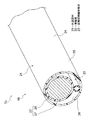
図2及び図3において、ハーネス本体19は、外装部材21と、この外装部材21に収容保護される一本又は二本の導電路22(図2は一本の場合、図3は二本の場合を示す)と、本発明の特徴部材である振動抑制線状部材23とを備えて構成される。尚、導電路22の本数に関し、本実施例に限らず三本以上であってもよいものとする。また、複数本の場合、高圧のワイヤハーネス9を一緒にしてもよいものとする。
<About the configuration of the
2 and 3, the
ハーネス本体19は、図1(b)の矢印Cの部分が曲げ配索部分、矢印Dの部分がストレートに配索する部分として用いられる。すなわち、曲げ配索部分Cは、車両取付形状(ワイヤハーネス配索先の形状。固定対象の形状)に合わせてワイヤハーネス15を曲げて配索する配索部分として用いられる。また、ストレートに配索する部分Dは、曲げ配索部分C、C同士の間の配索部分(車両床下11に配索される部分)として用いられる。
The harness
先ず、ハーネス本体19における外装部材21、導電路22について説明をし、次に、振動抑制線状部材23、ワイヤハーネス15の製造について説明をする。
First, the
<外装部材21について>
図2及び図3において、外装部材21は、樹脂成形にて一本の真っ直ぐな管体形状のものに形成される(使用前は真っ直ぐである。尚、樹脂製に限らず金属製であってもよいものとする)。また、外装部材21は、本実施例において腹割きなしの形状に形成される。別な言い方をすれば、スリットのない形状に形成される(割チューブでない形状に形成される)。さらに、外装部材21は、断面円形状に形成される。
<About the
2 and 3, the
このような外装部材21は、本実施例において、上記ストレートに配索する部分Dに対応する部分が直管形状のストレート管部24として形成される(一例であり、蛇腹管形状であってもよいものとする)。尚、ストレート管部24における引用符号25は管外面、26は管内面を示すものとする。
In the present embodiment, such an
外装部材21は、本発明において少なくともストレート管部24が形成される範囲に後述する振動抑制線状部材23が導電路22と一緒に挿通されるものとする。
In the
<導電路22について>
図2及び図3において、導電路22は、導電性を有する導体27と、この導体27の外側に設けられる絶縁性の絶縁体28とを備えて構成される。導体27は、銅や銅合金、或いはアルミニウムやアルミニウム合金により断面円形に形成される。導体27に関しては、素線を撚り合わせてなる導体構造のものや、断面矩形又は円形(丸形)になる棒状の導体構造(例えば平角単心や丸単心となる導体構造であり、この場合、電線自体も棒状となる)のもののいずれであってもよいものとする。以上のような導体27は、この外面に絶縁性の樹脂材料からなる絶縁体28が押出成形される。
<About the
2 and 3, the
絶縁体28は、熱可塑性樹脂材料を用いて導体27の外周面に押出成形される。絶縁体28の上記熱可塑性樹脂としては、公知の様々な種類のものが使用可能であるものとする。例えば、ポリ塩化ビニル樹脂やポリエチレン樹脂、ポリプロピレン樹脂などの高分子材料から適宜選択される。
The
尚、図3の導電路22は太さの異なる二本の例を示すが、これに限らず同じ太さの二本であってもよいものとする。
3 shows two examples having different thicknesses, the present invention is not limited to this, and two
<振動抑制線状部材23について>
図2及び図3において、振動抑制線状部材23は、外装部材21の内部所定範囲(本実施例ではストレート管部24が形成される範囲)での導電路22の遊び率(導電路22の振れが生じてしまうような空間の割合)を減らすような部材として用いられる。図においては、線状であり且つ弾力性を有する断面円形のチューブが採用される。尚、本実施例のようなゴム製のチューブの他に、樹脂製のチューブであってもよいものとする。また、断面円形状や多角形状のゴムひも等であってもよいものとする。振動抑制線状部材23は、外装部材21の上記空間の大きさに応じて適宜サイズのものが選択されるものとする。このような振動抑制線状部材23は、導電路22と一緒に外装部材21に挿通される。
<About the vibration suppression
2 and 3, the vibration suppressing
<ワイヤハーネス15の製造方法について>
図1において、ワイヤハーネス15は、先ずハーネス本体19の部分が製造される。そして、次に端末の加工が施される。図2及び図3において、ハーネス本体19の部分は、外装部材21の一端開口部から他端開口部に向けて導電路22と振動抑制線状部材23とを一緒に挿通することにより製造される。尚、挿通にあたっては、導電路22と振動抑制線状部材23とを例えばテープ巻き等で簡易的に固定すれば作業し易くなるのは勿論である。本実施例では一緒に挿通することとしているが、別々に挿通することも当然に可能であるものとする。導電路22と振動抑制線状部材23とが外装部材21に挿通されると、ストレート管部24の部分では、導電路22の振れが生じるような空間の割合が少なくなる。すなわち、導電路22の遊び率が減少するようになる。
<About the manufacturing method of the
In FIG. 1, the
<本発明のまとめ及び効果について>
以上、図1ないし図3を参照しながら説明してきたように、本発明のワイヤハーネス15は、管体形状の外装部材21と、この外装部材21に挿通・保護される一本又は二本の導電路22と、導電路22と一緒に外装部材21に挿通される線状の振動抑制線状部材23とを備えて構成される。振動抑制線状部材23は、外装部材21の少なくとも内部所定範囲での導電路22の遊び率を減らして振れを抑制するための部材として備えられる。具体的には、弾力性を有するチューブが振動抑制線状部材23として好適であり、このような振動抑制線状部材23を備えることによって導電路22は外装部材21との相対的な振れが抑制される。
<Summary and effect of the present invention>
As described above with reference to FIG. 1 to FIG. 3, the
従って、本発明のワイヤハーネス15によれば、外装部材22内での導電路21の振れを抑制することができる。これにより、導電路21の絶縁体が外装部材22の管内面に強く当たって損傷してしまうのを防止することができる(シールド機能を有する導電路の場合、編組や金属箔へのダメージを防止することができる)。
Therefore, according to the
本発明は本発明の主旨を変えない範囲で種々変更実施可能なことは勿論である。 It goes without saying that the present invention can be variously modified without departing from the spirit of the present invention.
1…ハイブリッド自動車、 2…エンジン、 3…モータユニット、 4…インバータユニット、 5…バッテリー、 6…エンジンルーム、 7…自動車後部、 8、9…ワイヤハーネス、 10…中間部、 11…車両床下、 12…ジャンクションブロック、 13…ハーネス端末、 14…シールドコネクタ、 15…ワイヤハーネス、 16…低圧バッテリー、 17…自動車前部、 18…補器、 19…ハーネス本体、 20…コネクタ、 21…外装部材、 22…導電路、 23…振動抑制線状部材、 24…ストレート管部、 25…管外面、 26…管内面、 27…導体、 28…絶縁体、 C…曲げ配索部分、 D…ストレートに配索する部分
DESCRIPTION OF
Claims (3)
当該ワイヤハーネスは、前記外装部材の少なくとも内部所定範囲での前記導電路の遊び率を減らして振れを抑制する線状の振動抑制線状部材を更に備える
ことを特徴とするワイヤハーネス。 In a wire harness comprising a tubular-shaped exterior member and one or a plurality of conductive paths inserted and protected by the exterior member,
The wire harness further includes a linear vibration suppression linear member that reduces a play rate of the conductive path in at least a predetermined range of the exterior member and suppresses a swing.
前記振動抑制線状部材は、前記導電路と一緒に前記外装部材に挿通され、且つ、弾力性を有するチューブである
ことを特徴とするワイヤハーネス。 The wire harness according to claim 1,
The vibration suppressing linear member is a tube that is inserted into the exterior member together with the conductive path and has elasticity.
前記内部所定範囲は、少なくとも当該ワイヤハーネスをストレートに配索する部分を対象にして設定される
ことを特徴とするワイヤハーネス。 In the wire harness according to claim 1 or 2,
The internal predetermined range is set for at least a portion in which the wire harness is routed straight.
Priority Applications (3)
| Application Number | Priority Date | Filing Date | Title |
|---|---|---|---|
| JP2015177229A JP6328594B2 (en) | 2015-09-09 | 2015-09-09 | Wire harness |
| US15/259,558 US10322685B2 (en) | 2015-09-09 | 2016-09-08 | Wire harness |
| DE102016217194.1A DE102016217194A1 (en) | 2015-09-09 | 2016-09-09 | harness |
Applications Claiming Priority (1)
| Application Number | Priority Date | Filing Date | Title |
|---|---|---|---|
| JP2015177229A JP6328594B2 (en) | 2015-09-09 | 2015-09-09 | Wire harness |
Publications (2)
| Publication Number | Publication Date |
|---|---|
| JP2017055540A true JP2017055540A (en) | 2017-03-16 |
| JP6328594B2 JP6328594B2 (en) | 2018-05-23 |
Family
ID=58055211
Family Applications (1)
| Application Number | Title | Priority Date | Filing Date |
|---|---|---|---|
| JP2015177229A Expired - Fee Related JP6328594B2 (en) | 2015-09-09 | 2015-09-09 | Wire harness |
Country Status (3)
| Country | Link |
|---|---|
| US (1) | US10322685B2 (en) |
| JP (1) | JP6328594B2 (en) |
| DE (1) | DE102016217194A1 (en) |
Cited By (1)
| Publication number | Priority date | Publication date | Assignee | Title |
|---|---|---|---|---|
| JP2024002110A (en) * | 2022-06-23 | 2024-01-11 | 住友電装株式会社 | wire harness |
Families Citing this family (1)
| Publication number | Priority date | Publication date | Assignee | Title |
|---|---|---|---|---|
| JP6881263B2 (en) * | 2017-11-30 | 2021-06-02 | 住友電装株式会社 | Wire harness |
Citations (4)
| Publication number | Priority date | Publication date | Assignee | Title |
|---|---|---|---|---|
| US3055967A (en) * | 1961-05-29 | 1962-09-25 | Lewis A Bondon | Coaxial cable with low effective dielectric constant and process of manufacture |
| US3749813A (en) * | 1972-05-31 | 1973-07-31 | A Shealy | Expanded self-damping electrical conductor |
| JP2006231939A (en) * | 2005-02-22 | 2006-09-07 | Aisin Seiki Co Ltd | Power supply device for sliding door |
| JP2014091383A (en) * | 2012-11-01 | 2014-05-19 | Shimano Inc | Cable for bicycle |
Family Cites Families (15)
| Publication number | Priority date | Publication date | Assignee | Title |
|---|---|---|---|---|
| US2732422A (en) * | 1956-01-24 | Electric cable | ||
| US1384173A (en) * | 1918-05-10 | 1921-07-12 | S K F Ball Bearing Company | Flexible bushing |
| US1686782A (en) * | 1922-10-14 | 1928-10-09 | Gen Cable Corp | Electrical cable |
| US2186793A (en) * | 1937-11-27 | 1940-01-09 | Anaconda Wire & Cable Co | Electric cable |
| BE480485A (en) * | 1945-09-07 | |||
| US3227800A (en) * | 1964-06-03 | 1966-01-04 | Lewis A Bondon | Coaxial cable and inner conductor support member |
| US3288916A (en) * | 1964-07-28 | 1966-11-29 | Columbian Rope Co | Multiple conductor cable with tubular foam filler insulation |
| US3829603A (en) * | 1973-04-26 | 1974-08-13 | Anaconda Co | Power cable with grounding conductors |
| US3857996A (en) * | 1973-06-18 | 1974-12-31 | Anaconda Co | Flexible power cable |
| US4533789A (en) * | 1983-02-11 | 1985-08-06 | Cable Technology Laboratories, Inc. | High voltage electric power cable with thermal expansion accommodation |
| US4767890A (en) * | 1986-11-17 | 1988-08-30 | Magnan David L | High fidelity audio cable |
| US5313020A (en) * | 1992-05-29 | 1994-05-17 | Western Atlas International, Inc. | Electrical cable |
| US5829485A (en) * | 1997-06-10 | 1998-11-03 | Bentley-Harris Inc. | Foam coated convoluted tubing |
| JP5758087B2 (en) | 2010-06-02 | 2015-08-05 | 矢崎総業株式会社 | Wire harness |
| JP6361084B2 (en) | 2014-03-13 | 2018-07-25 | アイコム株式会社 | Short-range wireless communication system, communication terminal, and communication method |
-
2015
- 2015-09-09 JP JP2015177229A patent/JP6328594B2/en not_active Expired - Fee Related
-
2016
- 2016-09-08 US US15/259,558 patent/US10322685B2/en active Active
- 2016-09-09 DE DE102016217194.1A patent/DE102016217194A1/en active Pending
Patent Citations (4)
| Publication number | Priority date | Publication date | Assignee | Title |
|---|---|---|---|---|
| US3055967A (en) * | 1961-05-29 | 1962-09-25 | Lewis A Bondon | Coaxial cable with low effective dielectric constant and process of manufacture |
| US3749813A (en) * | 1972-05-31 | 1973-07-31 | A Shealy | Expanded self-damping electrical conductor |
| JP2006231939A (en) * | 2005-02-22 | 2006-09-07 | Aisin Seiki Co Ltd | Power supply device for sliding door |
| JP2014091383A (en) * | 2012-11-01 | 2014-05-19 | Shimano Inc | Cable for bicycle |
Cited By (2)
| Publication number | Priority date | Publication date | Assignee | Title |
|---|---|---|---|---|
| JP2024002110A (en) * | 2022-06-23 | 2024-01-11 | 住友電装株式会社 | wire harness |
| JP7845080B2 (en) | 2022-06-23 | 2026-04-14 | 住友電装株式会社 | Wire harness |
Also Published As
| Publication number | Publication date |
|---|---|
| US20170066392A1 (en) | 2017-03-09 |
| JP6328594B2 (en) | 2018-05-23 |
| US10322685B2 (en) | 2019-06-18 |
| DE102016217194A1 (en) | 2017-03-09 |
Similar Documents
| Publication | Publication Date | Title |
|---|---|---|
| JP2016103310A (en) | Wire harness | |
| JP2015201284A (en) | wire harness | |
| JP6258907B2 (en) | Exterior member and wire harness | |
| JP2016032388A (en) | Wire harness | |
| JP6340036B2 (en) | Exterior end cap and wire harness | |
| JP2015201285A (en) | wire harness | |
| JP2017060206A (en) | Wire harness and method of manufacturing wire harness | |
| JP6150852B2 (en) | Exterior member and wire harness | |
| JP6356729B2 (en) | Wire harness | |
| JP6162757B2 (en) | Wire harness | |
| JP2018093656A (en) | Exterior end cap and wire harness | |
| JP6685497B2 (en) | Wire harness | |
| WO2014157260A1 (en) | Wire harness | |
| JP6045618B2 (en) | Exterior member and wire harness | |
| JP6328594B2 (en) | Wire harness | |
| JP6440669B2 (en) | Exterior end cap and wire harness | |
| JP6319752B2 (en) | Wire harness | |
| JP6145437B2 (en) | Exterior member for wire harness, and wire harness | |
| WO2014034896A1 (en) | Wire harness and method for manufacturing same | |
| JP6211039B2 (en) | Wiring harness wiring structure | |
| JP6371743B2 (en) | Wire harness | |
| JP6594128B2 (en) | Wire harness | |
| US20170167640A1 (en) | Corrugated tube and wire harness | |
| JP6594127B2 (en) | Wire harness | |
| JP6211036B2 (en) | Exterior member and wire harness |
Legal Events
| Date | Code | Title | Description |
|---|---|---|---|
| A977 | Report on retrieval |
Free format text: JAPANESE INTERMEDIATE CODE: A971007 Effective date: 20170828 |
|
| A131 | Notification of reasons for refusal |
Free format text: JAPANESE INTERMEDIATE CODE: A131 Effective date: 20170905 |
|
| A521 | Request for written amendment filed |
Free format text: JAPANESE INTERMEDIATE CODE: A523 Effective date: 20171101 |
|
| TRDD | Decision of grant or rejection written | ||
| A01 | Written decision to grant a patent or to grant a registration (utility model) |
Free format text: JAPANESE INTERMEDIATE CODE: A01 Effective date: 20180410 |
|
| A61 | First payment of annual fees (during grant procedure) |
Free format text: JAPANESE INTERMEDIATE CODE: A61 Effective date: 20180418 |
|
| R150 | Certificate of patent or registration of utility model |
Ref document number: 6328594 Country of ref document: JP Free format text: JAPANESE INTERMEDIATE CODE: R150 |
|
| R250 | Receipt of annual fees |
Free format text: JAPANESE INTERMEDIATE CODE: R250 |
|
| R250 | Receipt of annual fees |
Free format text: JAPANESE INTERMEDIATE CODE: R250 |
|
| R250 | Receipt of annual fees |
Free format text: JAPANESE INTERMEDIATE CODE: R250 |
|
| S531 | Written request for registration of change of domicile |
Free format text: JAPANESE INTERMEDIATE CODE: R313531 |
|
| R350 | Written notification of registration of transfer |
Free format text: JAPANESE INTERMEDIATE CODE: R350 |
|
| LAPS | Cancellation because of no payment of annual fees |