JP2017006503A - Radiographic imaging system and radiographic imaging device - Google Patents
Radiographic imaging system and radiographic imaging device Download PDFInfo
- Publication number
- JP2017006503A JP2017006503A JP2015127260A JP2015127260A JP2017006503A JP 2017006503 A JP2017006503 A JP 2017006503A JP 2015127260 A JP2015127260 A JP 2015127260A JP 2015127260 A JP2015127260 A JP 2015127260A JP 2017006503 A JP2017006503 A JP 2017006503A
- Authority
- JP
- Japan
- Prior art keywords
- value
- radiation
- difference
- exposure dose
- calculated
- Prior art date
- Legal status (The legal status is an assumption and is not a legal conclusion. Google has not performed a legal analysis and makes no representation as to the accuracy of the status listed.)
- Granted
Links
Images


Landscapes
- Apparatus For Radiation Diagnosis (AREA)
Abstract
【課題】累積被曝線量によりシンチレーターに感度ムラが発生した場合にはそれを的確に認識して、放射線画像撮影装置についてゲインキャリブレーションを行うことを的確に促すことが可能な放射線画像撮影システムや放射線画像撮影装置を提供する。
【解決手段】シンチレーター3と二次元状に配列された複数の放射線検出素子7を備える放射線画像撮影装置1の検出部Pを仮想的に分割した場合の領域Rnごとに取得された、照射線量に起因するラグの信号値の統計値Dlag_stを算出して、領域Rnごとの累積被曝線量Σdstを更新して記憶するとともに、領域Rn同士の累積被曝線量Σdstの差分の絶対値|ΔΣdst|を算出し、算出した絶対値|ΔΣdst|の中に設定された閾値ΔΣdth以上の絶対値|ΔΣdst|が存在すると判断した場合に、当該放射線画像撮影装置1についてゲインキャリブレーションの実行を促す報知を行う。
【選択図】図8Radiation imaging system and radiation capable of accurately recognizing when non-uniformity of sensitivity occurs in scintillator due to accumulated exposure dose, and promptly performing gain calibration for radiation imaging apparatus An image capturing apparatus is provided.
An irradiation dose obtained for each region Rn when a detection unit P of a radiographic imaging apparatus 1 including a scintillator 3 and a plurality of radiation detection elements 7 arranged two-dimensionally is virtually divided. The statistical value Dlag_st of the signal value of the resulting lag is calculated, the accumulated dose Σdst for each region Rn is updated and stored, and the absolute value | ΔΣdst | of the difference between the accumulated doses Σdst between the regions Rn is calculated. When it is determined that there is an absolute value | ΔΣdst | that is equal to or larger than the set threshold value ΔΣdth in the calculated absolute value | ΔΣdst |, the radiographic imaging apparatus 1 is notified to urge execution of gain calibration.
[Selection] Figure 8
Description
本発明は、放射線画像撮影システムおよび放射線画像撮影装置に係り、特に、シンチレーターを備える放射線画像撮影装置を備える放射線画像撮影システム等に関する。 The present invention relates to a radiographic image capturing system and a radiographic image capturing device, and more particularly to a radiographic image capturing system including a radiographic image capturing device including a scintillator.
放射線画像撮影時に、患者等の被写体を介して照射されたX線等の放射線をシンチレーターで可視光等の電磁波に変換して二次元状に配列された複数の放射線検出素子に照射し、放射線検出素子で、被写体を介して照射された放射線の線量(すなわちそれに対応する電磁波の光量)に応じた電気信号に変換して画像データとして読み出す放射線画像撮影装置(Flat Panel Detector:FPD)が種々開発され、病院等の施設に導入されている。 At the time of radiographic image capturing, radiation such as X-rays irradiated through a subject such as a patient is converted into electromagnetic waves such as visible light by a scintillator and irradiated to a plurality of radiation detection elements arranged in a two-dimensional form to detect radiation. Various radiographic imaging devices (Flat Panel Detector: FPD) have been developed, which are converted into electrical signals corresponding to the dose of radiation irradiated through the subject (ie, the amount of electromagnetic waves corresponding to the element) and read out as image data. Have been introduced in hospitals and other facilities.
そして、撮影ごとに放射線画像撮影装置のシンチレーターに放射線が照射されるため、シンチレーターは、累積する放射線の線量、すなわち累積被曝線量に応じて劣化して感度が低下する。そして、シンチレーターにおいて、累積被曝線量が相対的に大きく感度が低下した領域と、累積被曝線量が相対的に小さく劣化すなわち感度低下があまり進んでいない領域とで感度ムラが発生し、それらの領域が近接していると、放射線画像撮影装置で読み出された画像データ等に基づいて生成された放射線画像において、上記の感度ムラが画像上のムラ(すなわちいわゆる画像ムラ)として視認されてしまうという問題が生じ得る。そこで、シンチレーターの劣化による感度低下に対応して、通常、放射線検出素子のゲイン補正値をキャリブレーションするゲインキャリブレーションが行われる。 And since radiation is irradiated to the scintillator of a radiographic imaging apparatus for every imaging | photography, a scintillator deteriorates according to the accumulated dose of radiation, ie, accumulated exposure dose, and sensitivity falls. Then, in the scintillator, sensitivity unevenness occurs between the region where the cumulative exposure dose is relatively large and the sensitivity is reduced, and the region where the cumulative exposure dose is relatively small and the deterioration, i.e., the sensitivity reduction has not progressed so much. When close to each other, the above-mentioned sensitivity unevenness is visually recognized as unevenness on the image (that is, so-called image unevenness) in the radiographic image generated based on the image data read out by the radiographic apparatus. Can occur. Accordingly, gain calibration for calibrating the gain correction value of the radiation detection element is usually performed in response to the sensitivity reduction due to deterioration of the scintillator.
放射線画像撮影装置のゲインキャリブレーションについては、例えば定期的に行うように構成される場合がある。しかし、例えば比較的小規模な医院等において放射線画像撮影装置を用いる撮影の実施頻度がさほど多くなく、放射線画像撮影装置のシンチレーターの劣化による感度低下がさほど進んでいないにもかかわらず、定期的に放射線画像撮影装置のゲインキャリブレーションを行わなければならなくなるといった問題がある。また、比較的規模が大きい病院等でも、例えば使用頻度が多くない放射線画像撮影装置に対してもゲインキャリブレーションを定期的に行わなければならなくなる。 The gain calibration of the radiation image capturing apparatus may be configured to be performed periodically, for example. However, for example, in a relatively small clinic, the frequency of performing imaging using a radiographic imaging device is not so high, and the decrease in sensitivity due to deterioration of the scintillator of the radiographic imaging device has not progressed so much, but periodically. There is a problem that it is necessary to perform gain calibration of the radiation image capturing apparatus. Further, even in a relatively large hospital or the like, it is necessary to periodically perform gain calibration even for a radiographic imaging apparatus that is not frequently used, for example.
また、放射線画像撮影装置のゲインキャリブレーションの要否を判定するために、現状では、定期的に、被写体を介在させない状態で放射線画像撮影装置に対して一様に(すなわち放射線画像撮影装置に対して全面的にほぼ同じ線量の)放射線を照射して、放射線画像を撮影するように構成される場合がある。しかし、放射線画像撮影装置のゲインキャリブレーションの要否を判定するために、毎度、放射線を照射して画像を撮影するのは手間がかかる等の問題がある。 In addition, in order to determine whether or not the gain calibration of the radiographic imaging apparatus is necessary, at present, the radiographic imaging apparatus is regularly and uniformly (ie, to the radiographic imaging apparatus) with no subject interposed. In some cases, it is configured to take a radiation image by irradiating radiation of substantially the same dose over the entire surface. However, in order to determine whether or not the gain calibration of the radiographic imaging device is necessary, there is a problem that it takes time and effort to shoot an image by irradiating radiation each time.
そこで、例えば特許文献1には、放射線画像撮影装置で検出した放射線画像情報に基づいて、患者等の被写体を透過した放射線を放射線画像撮影装置で検出し、検出した放射線画像情報を撮影ごとに累積して累積被曝線量を算出し、算出した累積被曝線量と当該放射線画像撮影装置の許容累積被曝線量とを比較して、例えば累積被曝線量が許容累積被曝線量を超過した場合には、当該放射線画像撮影装置の感度低下による画質劣化が発生するおそれがあるとして、放射線画像撮影装置の交換やメンテナンスを促す警告を行う放射線画像撮影システムが開示されている。
Therefore, for example, in
このように構成すれば、上記のようにゲインキャリブレーションの要否判定のためにわざわざ放射線画像撮影装置に放射線を照射する必要がなく、撮影時に得られる放射線画像情報すなわち画像データ等を用いて、シンチレーターの感度の低下がどの程度進んだかを知ることが可能となり、ゲインキャリブレーション等のメンテナンスの要否を判断することが可能となる。 If constituted in this way, it is not necessary to irradiate radiation to the radiographic imaging device for the necessity determination of gain calibration as described above, and using radiographic image information obtained at the time of imaging, that is, image data, etc. It is possible to know how much the sensitivity reduction of the scintillator has progressed, and it is possible to determine the necessity of maintenance such as gain calibration.
しかしながら、被写体を透過せずに、放射線画像撮影装置に放射線が直接到達した部分(すなわちいわゆる素抜け部)では、到達した放射線の線量(すなわち被曝線量)が所定の線量以上になった場合に、放射線画像情報すなわち画像データが飽和(saturation。すなわち出力し得る最大値が出力されること。)を生じる場合があるが、画像データが飽和してしまうと、そのような画像データに基づいても実際にどれだけの線量の放射線が照射されたか(すなわち被曝線量)を算出することができない。 However, in a portion where radiation has directly reached the radiographic imaging apparatus without passing through the subject (that is, a so-called blank portion), when the amount of radiation that has reached (that is, the exposure dose) exceeds a predetermined dose, Radiation image information, that is, image data may be saturated (that is, a maximum value that can be output is output), but if image data is saturated, it is actually based on such image data. It is not possible to calculate how much radiation has been irradiated (ie exposure dose).
また、例えば、放射線画像撮影装置のシンチレーターにおいて全域的に一様に劣化が進み感度が低下している場合には、シンチレーターの各領域間で感度低下の度合にさほど差がないため、撮影された放射線画像上には、シンチレーターの感度ムラによる画像ムラは視認されない。しかし、このように画像ムラが視認されない場合でも、特許文献1に記載された放射線画像撮影システムでは、放射線画像撮影装置の累積被曝線量が許容累積被曝線量を超過していれば放射線画像撮影装置のメンテナンスを行うことを促す警告がなされることになる。
Also, for example, in the case of the scintillator of the radiographic image capturing apparatus, when the deterioration has progressed uniformly and the sensitivity has decreased, the image has been photographed because there is not much difference in the degree of sensitivity decrease between each region of the scintillator. On the radiographic image, image unevenness due to uneven sensitivity of the scintillator is not visually recognized. However, even when the image unevenness is not visually recognized in this way, in the radiographic imaging system described in
また、例えば、放射線画像撮影装置のシンチレーターのある領域で他の領域よりも劣化が進み感度が低下しており、シンチレーターの感度ムラによって放射線画像に画像ムラが生じる場合でも、特許文献1に記載された放射線画像撮影システムでは、放射線画像撮影装置の累積被曝線量が許容累積被曝線量を超過していなければ、放射線画像撮影装置のメンテナンスすなわちゲインキャリブレーション等を行うことを促す警告はなされないことになる。しかし、これでは、累積被曝線量によりシンチレーターに発生した感度ムラによって放射線画像に画像ムラが視認されてしまうことを防止することができない。
In addition, for example, even in the case where a certain area of the scintillator of the radiographic image capturing apparatus is deteriorated and sensitivity is lower than that of other areas, and unevenness in the radiation image occurs due to uneven sensitivity of the scintillator, it is described in
本発明は、上記の問題点を鑑みてなされたものであり、累積被曝線量によりシンチレーターに感度ムラが発生した場合にはそれを的確に認識して、放射線画像撮影装置についてゲインキャリブレーションを行うことを的確に促すことが可能な放射線画像撮影システムや放射線画像撮影装置を提供することを目的とする。 The present invention has been made in view of the above problems, and when a nonuniformity in sensitivity occurs in the scintillator due to the accumulated exposure dose, it is accurately recognized, and gain calibration is performed for the radiographic image capturing apparatus. An object of the present invention is to provide a radiographic image capturing system and a radiographic image capturing apparatus that can accurately prompt the user.
前記の問題を解決するために、本発明の放射線画像撮影システムや放射線画像撮影装置は、
シンチレーター、および二次元状に配列された複数の放射線検出素子を備える放射線画像撮影装置と、
前記放射線画像撮影装置の二次元状に配列された複数の前記放射線検出素子を仮想的に複数の領域に分割した場合の前記領域ごとに、前記放射線画像撮影装置で撮影後に放射線が照射されない状態で前記放射線検出素子ごとに取得された、照射線量に起因するラグの信号値の統計値を算出し、算出した前記領域ごとの前記ラグの信号値の統計値に基づいて当該領域における被曝線量の統計値を算出して、前記領域ごとに、算出した前記被曝線量の統計値を、過去に算出した被曝線量の統計値の積算値である累積被曝線量に加算して、前記領域ごとの累積被曝線量を更新する更新手段と、
更新された前記領域ごとの累積被曝線量を記憶する記憶手段と、
前記領域同士の前記累積被曝線量の差分の絶対値を算出する算出手段と、
算出された前記差分の絶対値の中に、設定された閾値以上の差分の絶対値が存在するか否かを判断する判断手段と、
前記判断手段により、前記差分の絶対値の中に前記閾値以上の差分の絶対値が存在すると判断された場合に、当該放射線画像撮影装置についてゲインキャリブレーションの実行を促す報知を行う報知手段と、
を備えることを特徴とする。
In order to solve the above problems, the radiographic imaging system and radiographic imaging apparatus of the present invention are:
A radiographic imaging apparatus comprising a scintillator and a plurality of radiation detection elements arranged two-dimensionally;
In a state where radiation is not irradiated after imaging by the radiographic imaging device for each of the regions when the plurality of the radiation detection elements arranged in a two-dimensional array of the radiographic imaging device are virtually divided into a plurality of regions. The statistical value of the signal value of the lag caused by the irradiation dose obtained for each of the radiation detection elements is calculated, and the statistical value of the exposure dose in the region based on the statistical value of the signal value of the lag for each of the calculated regions A value is calculated, and for each region, the calculated statistical value of the radiation dose is added to a cumulative radiation dose that is an integrated value of statistical values of the radiation dose calculated in the past, and a cumulative radiation dose for each region is calculated. Updating means for updating
Storage means for storing the cumulative exposure dose for each of the updated areas;
A calculating means for calculating an absolute value of a difference between the accumulated doses between the regions;
A judging means for judging whether or not an absolute value of a difference equal to or larger than a set threshold exists in the calculated absolute value of the difference;
An informing means for informing the radiographic imaging apparatus to execute gain calibration when the determining means determines that the absolute value of the difference equal to or greater than the threshold is present in the absolute value of the difference;
It is characterized by providing.
また、本発明の放射線画像撮影システムや放射線画像撮影装置は、
シンチレーター、および二次元状に配列された複数の放射線検出素子を備える放射線画像撮影装置と、
前記放射線画像撮影装置の二次元状に配列された複数の前記放射線検出素子を仮想的に複数の領域に分割した場合の前記領域ごとに、前記放射線画像撮影装置で撮影後に放射線が照射されない状態で前記放射線検出素子ごとに取得された、照射線量に起因するラグの信号値の統計値を算出し、算出した前記領域ごとの前記ラグの信号値の統計値に基づいて当該領域における被曝線量の統計値を算出する算出手段と、
前記領域同士の前記被曝線量の統計値の差分を算出し、算出した前記領域同士の被曝線量の統計値の差分を、過去に算出した前記領域同士の被曝線量の統計値の差分の累積値に加算して、前記領域同士の被曝線量の統計値の差分の累積値を更新する更新手段と、
更新された前記領域同士の被曝線量の統計値の差分の累積値を記憶する記憶手段と、
前記領域同士の被曝線量の統計値の差分の累積値の中に、その絶対値が、設定された閾値以上の差分の累積値が存在するか否かを判断する判断手段と、
前記判断手段により、前記差分の累積値の中に、その絶対値が前記閾値以上の差分の累積値が存在すると判断された場合に、当該放射線画像撮影装置についてゲインキャリブレーションの実行を促す報知を行う報知手段と、
を備えることを特徴とする。
Moreover, the radiographic imaging system and radiographic imaging device of the present invention are:
A radiographic imaging apparatus comprising a scintillator and a plurality of radiation detection elements arranged two-dimensionally;
In a state where radiation is not irradiated after imaging by the radiographic imaging device for each of the regions when the plurality of the radiation detection elements arranged in a two-dimensional array of the radiographic imaging device are virtually divided into a plurality of regions. The statistical value of the signal value of the lag caused by the irradiation dose obtained for each of the radiation detection elements is calculated, and the statistical value of the exposure dose in the region based on the statistical value of the signal value of the lag for each of the calculated regions A calculating means for calculating a value;
The difference in the statistical value of the exposure dose between the areas is calculated, and the difference in the statistical value of the exposure dose between the calculated areas is set to the cumulative value of the difference in the statistical value of the exposure dose between the areas calculated in the past. In addition, update means for updating the cumulative value of the difference in the statistical value of the exposure dose between the regions,
Storage means for storing a cumulative value of a difference in statistical values of exposure dose between the updated areas;
In the cumulative value of the difference between the statistical values of the exposure dose between the regions, a determination means for determining whether or not the absolute value of the cumulative value of the difference equal to or more than a set threshold exists,
When the determination means determines that a cumulative value of a difference whose absolute value is greater than or equal to the threshold value is present in the cumulative value of the difference, a notification that prompts execution of gain calibration for the radiographic imaging device Notification means to perform;
It is characterized by providing.
本発明のような方式の放射線画像撮影システムおよび放射線画像撮影装置によれば、累積被曝線量によりシンチレーターに感度ムラが発生した場合にはそれを的確に認識して、放射線画像撮影装置についてゲインキャリブレーションを行うことを的確に促すことが可能となる。 According to the radiation image capturing system and the radiation image capturing apparatus of the system as in the present invention, when the sensitivity unevenness occurs in the scintillator due to the accumulated exposure dose, it is accurately recognized and the gain calibration is performed for the radiation image capturing apparatus. It is possible to promptly promote to perform.
そして、報知を受けたユーザーが、自らゲインキャリブレーションを行ったり、サービスマンを呼んでゲインキャリブレーションを行わせたり、或いは製造元に放射線画像撮影装置を送る等して、当該放射線画像撮影装置に対して的確にゲインキャリブレーションを行うことが可能となり、当該放射線画像撮影装置を用いて撮影された放射線画像中に、シンチレーターの感度ムラに起因する画像ムラが視認される状態になることを的確に防止することが可能となる。 Then, the user who has received the notification performs gain calibration by himself, calls a service person to perform gain calibration, or sends the radiographic imaging apparatus to the manufacturer, etc. Gain calibration can be performed accurately, and it is possible to accurately prevent image unevenness due to the sensitivity variation of the scintillator from being visible in the radiographic image captured using the radiographic image capturing apparatus. It becomes possible to do.
以下、本発明に係る放射線画像撮影システムの実施の形態について、図面を参照して説明する。 Embodiments of a radiation image capturing system according to the present invention will be described below with reference to the drawings.
なお、以下では、放射線画像撮影システムに属する、放射線画像撮影装置以外のコンピューター(すなわち放射線画像撮影装置とは別体のコンピューター)で、表示部上に表示したり音声を発生させて、ゲインキャリブレーションの実行を促す報知を行う場合について説明するが、放射線画像撮影装置で全ての処理を行い、放射線画像撮影装置の後述するインジケーター40(後述する図1参照)を所定の色で点灯、点滅させたり、或いは放射線画像撮影装置に設けた液晶ディプスレイ等の図示しない表示部上に表示させたり、図示しないスピーカーから音声を発生させたりして、上記の報知を行うように構成することも可能である。この場合は、後述する放射線画像撮影装置1の制御手段22が、インジケーター40や表示部、スピーカー等を介して、放射線画像撮影装置についてゲインキャリブレーションの実行を促す報知を行う後述する報知手段として機能することになる。
In the following description, gain calibration is performed by displaying on a display unit or generating sound by using a computer other than the radiographic imaging apparatus (that is, a computer separate from the radiographic imaging apparatus) belonging to the radiographic imaging system. However, the radiographic imaging apparatus performs all the processing, and the indicator 40 (see FIG. 1 to be described later) of the radiographic imaging apparatus is turned on and blinked in a predetermined color. Alternatively, the above notification may be performed by displaying on a display unit (not shown) such as a liquid crystal display provided in the radiographic imaging apparatus or by generating sound from a speaker (not shown). In this case, the control means 22 of the radiographic
また、以下では、放射線画像撮影装置が、センサーパネルSPが筐体2内に収納された、いわゆる可搬型である場合について説明するが、センサーパネルSpが支持台等と一体的に形成された、いわゆる専用機型(据え付け型等ともいう。)の放射線画像撮影装置に対しても、本発明を適用することが可能である。
In the following, a case where the radiographic image capturing apparatus is a so-called portable type in which the sensor panel SP is housed in the
[放射線画像撮影装置]
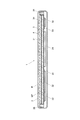
本実施形態に係る放射線画像撮影装置の基本的な構成について簡単に説明する。図1は、放射線画像撮影装置の外観を示す斜視図であり、図2は、図1のX−X線に沿う断面図である。本実施形態では、放射線画像撮影装置1は、図1や図2に示すように、筐体状のハウジング2内にシンチレーター3やセンサー基板4等で構成されるセンサーパネルSPが収納されて構成されている。本実施形態では、筐体2は、放射線入射面Rを有する中空の角筒状のハウジング本体部2Aの両側の開口部を蓋部材2B、2Cで閉塞することで形成されている。
[Radiation imaging equipment]
A basic configuration of the radiographic image capturing apparatus according to the present embodiment will be briefly described. FIG. 1 is a perspective view showing an external appearance of the radiographic image capturing apparatus, and FIG. 2 is a cross-sectional view taken along line XX of FIG. In this embodiment, the
そして、図1に示すように、筐体2の一方側の蓋部材2Bには、電源スイッチ37や切替スイッチ38、コネクター39、インジケーター40等が配置されている。また、本実施形態では、筐体2の例えば反対側の側面等に、外部装置と無線方式で通信を行うためのアンテナ41(後述する図3参照)が設けられている。また、コネクター39を介して外部から電力の供給を受けたり、或いは外部装置と有線方式で通信を行うこともできるようになっている。
As shown in FIG. 1, a
また、図2に示すように、筐体2内には、基台31が配置されており、基台31の放射線入射面R側に、図示しない鉛の薄板等を介してセンサー基板4が設けられている。そして、センサー基板4の上面側には、照射された放射線を可視光等の光に変換するシンチレーター3がシンチレーター基板34上に設けられ、シンチレーター3がセンサー基板4側に対向する状態で設けられている。また、基台31の下面側には、電子部品32等が配設されたPCB基板33やバッテリー24等が取り付けられている。
As shown in FIG. 2, a
本実施形態では、このようにしてセンサーパネルSPが形成されている。また、センサーパネルSPと筐体2の側面との間に緩衝材35が設けられている。なお、本実施形態では、シンチレーター3として、CsI:Tl等の母体材料内に発光中心物質が付活された蛍光体を柱状に成長させた蛍光体の柱状結晶からなるシンチレーターが採用されているが、シンチレーター3は、例えばシンチレーター基板34等にペースト状の蛍光体を塗布して形成されるいわゆる塗布型のシンチレーターであってもよい。
In the present embodiment, the sensor panel SP is formed in this way. In addition, a
図3は、放射線画像撮影装置の等価回路を表すブロック図である。図3に示すように、放射線画像撮影装置1には、図示しないセンサー基板上に複数の放射線検出素子7が二次元状(マトリクス状)に配列されており、複数の放射線検出素子7が二次元状に配列された領域全体、すなわち図3に一点鎖線で示される領域が検出部Pとされている。
FIG. 3 is a block diagram showing an equivalent circuit of the radiation image capturing apparatus. As shown in FIG. 3, in the
そして、各放射線検出素子7は、照射された放射線の線量に応じた電荷(正確には照射された放射線がシンチレーター3で変換された電磁波が放射線検出素子7に照射された際の照射された電磁波の光量に応じた電荷)を発生させるようになっている。本実施形態では、放射線検出素子7はフォトダイオードが用いられているが、例えばフォトトランジスターやCCD(Charge Coupled Device)イメージセンサー等を用いることも可能である。
Each radiation detection element 7 has an electric charge corresponding to the dose of the irradiated radiation (more precisely, the electromagnetic wave irradiated when the radiation detection element 7 is irradiated with an electromagnetic wave obtained by converting the irradiated radiation by the
各放射線検出素子7には、バイアス線9が接続されており、バイアス線9は結線10に接続されている。そして、結線10はバイアス電源14に接続されており、バイアス電源14からバイアス線9等を介して各放射線検出素子7に逆バイアス電圧が印加されるようになっている。
A bias line 9 is connected to each radiation detection element 7, and the bias line 9 is connected to a
また、各放射線検出素子7には、薄膜トランジスター(Thin Film Transistor。以下、TFTという。)8がスイッチ素子として接続されており、TFT8は信号線6に接続されている。また、走査駆動手段15では、配線15cを介して電源回路15aから供給されたオン電圧とオフ電圧がゲートドライバー15bで切り替えられて走査線5の各ラインL1〜Lxに印加されるようになっている。そして、各TFT8は、走査線5を介してオン電圧が印加されるとオン状態になって、放射線検出素子7内に蓄積された電荷を信号線6に放出させ、また、走査線5を介してオフ電圧が印加されるとオフ状態になって、放射線検出素子7と信号線6との導通を遮断して、放射線検出素子7内で発生した電荷を放射線検出素子7内に蓄積させるようになっている。
Each radiation detection element 7 is connected to a thin film transistor (hereinafter referred to as TFT) 8 as a switch element, and the TFT 8 is connected to the
読み出しIC16内には複数の読み出し回路17が設けられており、読み出し回路17にはそれぞれ信号線6が接続されている。そして、画像データDの読み出し処理の際には、放射線検出素子7から電荷が放出されると、電荷は信号線6を介して読み出し回路17に流れ込み、増幅回路18では流れ込んだ電荷の量に応じた電圧値が出力される。そして、相関二重サンプリング回路(図3では「CDS」と記載されている。)19は、増幅回路18から出力された電圧値をアナログ値の画像データDとして読み出して下流側に出力する。そして、出力された画像データDはアナログマルチプレクサー21を介してA/D変換器20に順次送信され、A/D変換器20でデジタル値の画像データDに順次変換され、記憶手段23に出力されて順次保存されるようになっている。
A plurality of
制御手段22は、図示しないCPU(Central Processing Unit)やROM(Read Only Memory)、RAM(Random Access Memory)、入出力インターフェース等がバスに接続されたコンピューターや、FPGA(Field Programmable Gate Array)等で構成されている。専用の制御回路で構成されていてもよい。制御手段22には、SRAM(Static RAM)やSDRAM(Synchronous DRAM)、NAND型フラッシュメモリー等で構成される記憶手段23が接続されている。 The control means 22 is a CPU (Central Processing Unit), a ROM (Read Only Memory), a RAM (Random Access Memory), an input / output interface, etc., not shown, connected to the bus, an FPGA (Field Programmable Gate Array), or the like. It is configured. It may be configured by a dedicated control circuit. The control means 22 is connected to a storage means 23 composed of SRAM (Static RAM), SDRAM (Synchronous DRAM), NAND flash memory or the like.
また、制御手段22には、走査駆動手段15や読み出し回路17、記憶手段23、バイアス電源14等の各機能部に必要な電力を供給する電源24、アンテナ41やコネクター39を介する外部との無線方式や有線方式での通信を制御するための通信部25等が接続されている。そして、制御手段22は、画像データDの読み出し処理の際には、上記のように走査駆動手段15や読み出し回路17等の動作を制御して、各放射線検出素子7から放出させた電荷を画像データDとして読み出させるようになっている。
The
[放射線画像撮影装置の使用環境等について]
次に、本実施形態に係る放射線画像撮影装置1が用いられる使用環境等について簡単に説明する。放射線画像撮影装置1が用いられる使用環境として、図4では、放射線画像撮影装置1が撮影室での撮影に使用される場合が例示されており、また、図5では、放射線画像撮影装置1が病室等に持ち込まれて撮影が行われる場合が例示されている。
[Usage environment etc. of radiation imaging equipment]
Next, a usage environment in which the radiation
図4に示すように、放射線画像撮影装置1が撮影室Raでの撮影に用いられる場合、放射線画像撮影装置1は、通常、ブッキー装置51のカセッテ保持部(カセッテホルダー等ともいう。)51aに装填される。なお、図4では、ブッキー装置51として、立位撮影用のブッキー装置51Aや臥位撮影用のブッキー装置51Bが設置されている場合が示されている。
As shown in FIG. 4, when the
撮影室Raには、図示しない被写体を介してブッキー装置51に装填された放射線画像撮影装置1に放射線を照射する放射線照射装置52Aが少なくとも1つ設けられている。また、撮影室Raには、撮影室Ra内の各装置等や撮影室Ra外の各装置等の間の無線方式や有線方式での通信等を中継するためのアクセスポイント53を備えた中継器54が設けられている。また、中継器54には、放射線照射装置52のジェネレーター55や後述するコンソール58等も接続されており、中継器54は、放射線画像撮影装置1やコンソール58、放射線照射装置52のジェネレーター55等との間の通信や画像データDの転送を中継するようになっている。
The imaging room Ra is provided with at least one
前室(操作室等ともいう。)Rbには、放射線照射装置52の操作卓57が設けられており、操作卓57には、放射線技師等の操作者が操作してジェネレーター55に対して放射線の照射開始等を指示するための曝射スイッチ56が設けられている。ジェネレーター55は、放射線照射装置52から適切な線量の放射線が照射されるように、放射線照射装置52に対して管電流や照射時間等を設定するなど種々の制御を行うようになっている。
The front room (also referred to as an operation room or the like) Rb is provided with an
また、コンピューター等で構成されたコンソール58が前室Rbに設けられている。なお、コンソール58を撮影室Raや前室Rbの外側や別室等に設けるように構成することも可能である。コンソール58には、CRT(Cathode Ray Tube)やLCD(Liquid Crystal Display)等を備えて構成される表示部58aが設けられており、また、マウスやキーボード等の入力手段58bを備えている。また、コンソール58には、HDD(Hard Disk Drive)等で構成された記憶手段59が接続され、或いは内蔵されている。
A
一方、放射線画像撮影装置1が病室Rcや患者の自宅等に持ち込まれて撮影が行われる場合、図5に示すように、放射線画像撮影装置1は、ベッドBと患者Hとの間に差し込まれたり患者Hの身体にあてがわれたりして用いられる。また、病室Rc等で撮影を行う場合、図5に示すように、いわゆるポータブルの放射線照射装置52P等が例えば回診車71に搭載される等して病室Rc等に持ち込まれる。
On the other hand, when the radiographic
この場合、アクセスポイント53が設けられた中継器54が回診車71に内蔵されており、上記と同様に、中継器54が放射線照射装置52のジェネレーター55とコンソール58との間の通信や、放射線画像撮影装置1とコンソール58との間の通信や画像データDの転送等を中継するようになっている。なお、図5では、コンソール58の入力手段58bや記憶手段59等の図示が省略されている。
In this case, the
[撮影時における放射線画像撮影装置の処理等について]
ここで、撮影時における放射線画像撮影装置1の処理等について説明する。放射線画像撮影装置1は、コンソール58から撮影開始の信号を受信すると、撮影の前処理として、各放射線検出素子7内に残存する電荷を除去する放射線検出素子7のリセット処理等を開始する。
[Processing of the radiographic imaging device during radiography]
Here, the process of the
放射線検出素子7のリセット処理は、例えば図6に示すように、走査駆動手段15のゲートドライバー15b(図3参照)から走査線5の各ラインL1〜Lxにオフ電圧を順次印加し、各TFT8を順次オン状態にして、放射線検出素子7内に残存する電荷を信号線6に放出させるようにして行われる。なお、放射線検出素子7のリセット処理を、例えば、放射線技師等が、放射線照射装置52の曝射スイッチ56に対する1段目の操作(すなわちいわゆる半押し操作)を行った時点で開始するように構成することも可能であり、リセット処理の開始のタイミングは適宜決められる。
For example, as shown in FIG. 6, the radiation detection element 7 is reset by sequentially applying an off voltage to the lines L <b> 1 to Lx of the
そして、放射線技師等が、放射線照射装置52の曝射スイッチ56に対する2段目の操作(すなわちいわゆる全押し操作)を行うと、放射線照射装置52のジェネレーター55は放射線画像撮影装置1に照射開始信号を送信する。
Then, when a radiation engineer or the like performs a second-stage operation on the
放射線画像撮影装置1の制御手段22は、照射開始信号を受信すると、図6に示すように、その時点で行っている放射線検出素子7のリセット処理を、ゲートドライバー15bから走査線5の最終ラインLxに印加して1フレーム分の放射線検出素子7のリセット処理が完了した時点で終了させ、ゲートドライバー15bから走査線5の各ラインL1〜Lxにオフ電圧を印加し、各TFT8をオフ状態にして電荷蓄積状態に移行させる。
When receiving the irradiation start signal, the control means 22 of the
また、放射線画像撮影装置1の制御手段22は、それとともに、放射線照射装置52側にインターロック解除信号を送信する。そして、放射線照射装置52のジェネレーター55は、インターロック解除信号を受信した時点で、放射線照射装置52から放射線を照射させる。図6の斜線部分は、放射線照射装置52から放射線が照射されている期間を表す。
In addition, the control means 22 of the radiographic
そして、放射線画像撮影装置1の制御手段22は、図6に示すように、所定時間τだけ電荷蓄積状態を継続させた後、ゲートドライバー15bから走査線5の各ラインL1〜Lxにオン電圧を順次印加させて、各放射線検出素子7から放出された電荷を読み出し回路17で画像データDとして読み出す画像データDの読み出し処理を行わせる。
Then, as shown in FIG. 6, the
また、放射線画像撮影装置1では、撮影後に、図7に示すよう、オフセットデータOの読み出し処理が行われるようになっている。すなわち、放射線画像撮影装置1は、図6に示した画像データDの読み出し処理までの処理シーケンスと同じ処理シーケンスを、放射線が照射されない状態で繰り返して(すなわち放射線検出素子7のリセット処理を行い、放射線が照射されない状態で所定時間τだけ電荷蓄積状態を継続させた後、ゲートドライバー15bから走査線5の各ラインL1〜Lxにオン電圧を順次印加させて)、上記の画像データDの読み出し処理と同様にして各放射線検出素子7からオフセットデータOを読み出すオフセットデータOの読み出し処理が行われるようになっている。
Further, in the radiographic
また、放射線画像撮影装置1では、撮影後に、図7に示すよう、オフセットデータOを取得する動作が行われるようになっている。すなわち、放射線画像撮影装置1は、図6に示した画像データDを取得する動作までの処理シーケンスと同様の処理シーケンスを、放射線が照射されない状態で繰り返して(すなわち放射線検出素子7のリセット処理を行い、放射線が照射されない状態で所定時間τだけ電荷蓄積状態を継続させた後、ゲートドライバー15bから走査線5の各ラインL1〜Lxにオン電圧を順次印加させて)、各放射線検出素子7からオフセットデータOを取得する動作が行われるようになっている。
Moreover, in the
なお、上記のように、放射線画像撮影装置1と放射線照射装置52側との間で信号(すなわち照射開始信号やインターロック解除信号等)のやり取りを行いながら撮影を行うように構成される場合もあるが、放射線画像撮影装置1と放射線照射装置52側との間で信号等のやり取りを行わず、放射線画像撮影装置1が自ら放射線の照射が開始されたことを検出して電荷蓄積状態に移行する等して撮影を行うように構成される場合もある。なお、このように放射線画像撮影装置1が放射線の照射開始を検出する場合の構成等については、特開2009−219538号公報や国際公開第2011/135917号、国際公開第2011/152093号に詳しく記載されており、それらを参照されたい。
In addition, as described above, there may be a case where imaging is performed while exchanging signals (that is, an irradiation start signal, an interlock release signal, etc.) between the radiation
そして、このように構成される場合も、放射線画像撮影装置1では、撮影後に、上記と同様に、画像データDを取得する動作の処理シーケンスと同様の処理シーケンスが繰り返されて(なお、放射線が照射されない状態で行われる。)、オフセットデータOを取得する動作が行われるように構成される。
Even in such a configuration, the
また、放射線画像撮影装置1の制御手段22は、上記のようにして画像データDやオフセットデータOを読み出すと、読み出した画像データDやオフセットデータOをコンソール50に転送する。そして、コンソール58は、下記(1)式に従って放射線検出素子7ごとに画像データDからオフセットデータOを減算していわゆる真の画像データD*を算出し、算出した真の画像データD*に対してゲイン補正や欠陥画素補正、撮影部位に応じた階調処理等の画像処理を行って放射線画像を生成するように構成される。
D*=D−O …(1)
Further, when the
D * = DO (1)
[ゲインキャリブレーションの要否の判断処理および報知処理について]
次に、放射線画像撮影装置1に対するゲインキャリブレーションの要否の判断処理や報知処理のための構成等について説明する。また、本実施形態に係る放射線画像システム100(上記のように放射線画像撮影装置1で全ての処理を行うように構成する場合には放射線画像撮影装置1)の作用についてもあわせて説明する。
[About gain calibration necessity determination processing and notification processing]
Next, a configuration for determining whether or not gain calibration is necessary for the radiation
[前提となる事項について]
本実施形態では、放射線画像撮影装置1の二次元状に配列された複数の放射線検出素子7が、仮想的に複数の領域に分割されている。すなわち、前述したように、放射線画像撮影装置1の図示しないセンサー基板上に複数の放射線検出素子7が二次元状に配列されて検出部P(図3参照)が形成されているが、図8に示すように、本実施形態では、検出部P(すなわち複数の放射線検出素子7。以下同じ。)が仮想的に複数の領域R1〜Rzに分割されている。
[Assumptions]
In the present embodiment, the plurality of radiation detection elements 7 arranged in a two-dimensional shape of the radiation
各領域のR1〜Rzのサイズは、例えば100×100画素(すなわち100×100個の放射線検出素子7)等の適宜のサイズに設定される。なお、検出部Pが実際に物理的に複数の領域R1〜Rzに分割されるわけではなく、検出部Pを複数の領域R1〜Rzに分けて考えるということであり、その意味で「仮想的に分割」と表現されている。また、図8では、検出部Pが8×10個の各領域R1〜Rzに分割される場合が示されているが、本発明はそのように分割する場合に限定されない。 The size of R1 to Rz in each region is set to an appropriate size such as 100 × 100 pixels (that is, 100 × 100 radiation detection elements 7), for example. Note that the detection unit P is not actually physically divided into the plurality of regions R1 to Rz, but the detection unit P is considered to be divided into the plurality of regions R1 to Rz. Divided into two parts. Moreover, although the case where the detection part P is divided | segmented into each 8 * 10 area | region R1-Rz is shown in FIG. 8, this invention is not limited to the case where it divides | segments in that way.
また、前述した特許文献1に記載の発明のように放射線画像撮影装置1で読み出された画像データDに基づいて放射線検出素子7ごと(或いは本実施形態のように検出部Pの各領域R1〜Rzごと)の被曝線量を算出するように構成すると、放射線画像撮影装置1に放射線が直接到達した部分(すなわち検出部Pにおける素抜け部)等で読み出された画像データDが飽和した場合には、画像データDに基づいても実際にどれだけの線量の放射線が照射されたかが分からず被曝線量を精度良く算出することができない。
Further, as in the invention described in
そこで、本実施形態では、画像データDではなく、上記のオフセットデータOを用いて被曝線量を算出するようになっている。より正確に説明すると、図7に示したように、放射線画像撮影装置1の各放射線検出素子7について撮影後に読み出されたオフセットデータOには、放射線検出素子7の熱(温度)に起因して放射線検出素子7内で常時生じている暗電荷(暗電流等ともいう。)によるオフセット分oの他に、照射線量に起因するラグの信号値Dlagが含まれている。すなわち、オフセットデータOとラグの信号値Dlagと暗電荷によるオフセット分oと間には、
O=Dlag+o
∴Dlag=O−o …(2)
の関係がある。
Therefore, in the present embodiment, the exposure dose is calculated using the offset data O, not the image data D. More precisely, as shown in FIG. 7, the offset data O read out after imaging for each radiation detection element 7 of the
O = Dlag + o
∴Dlag = O-o (2)
There is a relationship.
なお、本実施形態では、以下、このラグの信号値Dlagに基づいて被曝線量を算出する場合について説明するが、上記のようにオフセットデータOにはラグの信号値Dlagが含まれており、オフセットデータOの値をそのまま用いても十分に精度良く被曝線量を算出することができる場合もある。そのため、そのような場合には、オフセットデータOから暗電荷によるオフセット分oを減算してラグの信号値Dlagを算出する代わりに、オフセットデータOをそのまま用いて、下記の処理を行うように構成することも可能である。そして、その場合は、下記の説明におけるラグの信号値DlagをオフセットデータOと読み替えて説明される。 In the present embodiment, the case where the exposure dose is calculated based on the lag signal value Dlag will be described below. However, as described above, the offset data O includes the lag signal value Dlag, and the offset Even if the value of the data O is used as it is, the exposure dose can be calculated with sufficient accuracy. Therefore, in such a case, instead of subtracting the offset o due to the dark charge from the offset data O to calculate the lag signal value Dlag, the following processing is performed using the offset data O as it is. It is also possible to do. In this case, the lag signal value Dlag in the following description is read as offset data O.
ここで、ラグ(lag)について説明すると、放射線画像撮影装置1に放射線が照射されると各放射線検出素子7内で電荷(すなわち電子正孔対)が発生し、それが前述した画像データDの読み出し処理で画像データDとして読み出されるが、その際、読み残し等により放射線検出素子7内に残存する電荷は前述した放射線検出素子7のリセット処理を行うと放射線検出素子7内から容易に除去される。しかし、放射線の照射により発生したラグは、放射線検出素子7のリセット処理を繰り返し行っても放射線検出素子7内から容易には消えないことが分かっている。
Here, the lag will be described. When the radiation
このようにラグが容易に消えない理由は、放射線の照射により放射線検出素子7内で発生した電子や正孔の一部が、一種の準安定なエネルギーレベル(metastable state)に遷移して、放射線検出素子内での移動性を失った状態が比較的長時間保たれるためと考えられている。そして、この準安定なエネルギー状態の電子や正孔は、いつまでも準安定なエネルギーレベルにあるわけではなく、熱エネルギーによって、ある確率で少しずつこの準安定なエネルギーよりも高いと考えられるエネルギーレベルの伝導帯に遷移して移動性が復活する。しかし、その割合が必ずしも大きくないため、各放射線検出素子7のリセット処理を繰り返し行っても容易に消えないと考えられている。なお、このラグの発生や持続のメカニズムについては、未だ不明な点が多い。 The reason why the lag does not disappear easily in this way is that some of the electrons and holes generated in the radiation detection element 7 due to the irradiation of radiation are changed to a kind of metastable state, and the radiation This is considered to be because the state of loss of mobility in the detection element is maintained for a relatively long time. And the electrons and holes in this metastable energy state are not always in the metastable energy level, but the energy level that is considered to be higher than the metastable energy little by little with thermal energy. Transition to the conduction band restores mobility. However, since the ratio is not necessarily large, it is considered that even if the reset process of each radiation detection element 7 is repeatedly performed, it does not easily disappear. There are still many unclear points about the mechanism of lag generation and persistence.
このように、発生したラグはなかなか消えないため、放射線の照射直後、画像データDの読み出し処理(図6参照)が行われた後のオフセットデータOの読み出し処理(図7参照)が行われる際にも各放射線検出素子7から読み出される。そのため、上記のように、オフセットデータO中にラグに基づく信号値すなわちラグの信号値Dlagが含まれることになる。 As described above, since the generated lag does not disappear easily, the offset data O reading process (see FIG. 7) is performed immediately after the irradiation of radiation and the reading process of the image data D (see FIG. 6) is performed. Also read out from each radiation detection element 7. Therefore, as described above, the offset data O includes the signal value based on the lag, that is, the signal value Dlag of the lag.
一方、本発明者らの研究では、撮影時に放射線検出素子7に照射された放射線の線量dすなわち放射線検出素子7の被曝線量dと、上記(2)式に従って算出されるラグの信号値Dlagとは、例えば図9に示すように単調増加の関係にあることが分かっている。そして、この場合、画像データDが飽和する場合の値に対応する線量dlimit以上の線量の放射線が放射線検出素子7に照射された場合でも、放射線検出素子7の被曝線量dが増加するとラグの信号値Dlagも増加する関係になる。 On the other hand, in the study by the present inventors, the dose d of the radiation applied to the radiation detection element 7 during imaging, that is, the exposure dose d of the radiation detection element 7, and the signal value Dlag of the lag calculated according to the above equation (2) Is known to have a monotonically increasing relationship as shown in FIG. 9, for example. In this case, even when the radiation detection element 7 is irradiated with a dose of radiation equal to or higher than the dose dlimit corresponding to the value when the image data D is saturated, the lag signal is increased when the radiation dose d of the radiation detection element 7 increases. The value Dlag also increases.
そのため、本実施形態では、画像データDが飽和するような被曝線量dlimit以上の線量の放射線が放射線検出素子7に照射された場合でも、図9に示した関係を参照することで、ラグの信号値Dlagに基づいて、放射線検出素子7の被曝線量を的確に算出することが可能となる。 For this reason, in the present embodiment, even when the radiation detection element 7 is irradiated with a radiation dose equal to or higher than the exposure dose dlimit that saturates the image data D, the lag signal can be obtained by referring to the relationship shown in FIG. Based on the value Dlag, the exposure dose of the radiation detection element 7 can be accurately calculated.
なお、上記(2)式に従ってラグの信号値Dlagを算出するためには、撮影時に放射線検出素子7ごとに読み出されるオフセットデータOの他に、放射線検出素子7ごとの暗電荷によるオフセット分oのデータが必要になる。暗電荷によるオフセット分oは、上記のような撮影時に発生するラグとは関係なく、前述したように、放射線検出素子7の熱(温度)に起因して放射線検出素子7内で常時生じている暗電荷に起因するオフセット分oである。 In order to calculate the lag signal value Dlag according to the above equation (2), in addition to the offset data O read for each radiation detection element 7 at the time of imaging, the offset o due to the dark charge for each radiation detection element 7 is calculated. Data is needed. The offset o due to the dark charge is always generated in the radiation detection element 7 due to the heat (temperature) of the radiation detection element 7 as described above, regardless of the lag generated during imaging as described above. This is an offset o due to dark charge.
そのため、例えば放射線画像撮影装置1の工場出荷時等に、例えば図7に示したオフセットデータOの読み出し処理までの処理シーケンスを、放射線画像撮影装置1に放射線が照射されない状態で行うことで、暗電荷によるオフセット分oを予め読み出しておくように構成することが可能である。また、暗電荷によるオフセット分oを、このように予め読み出しておく代わりに、例えば撮影ごとに、或いは放射線画像撮影装置1を用いて撮影を行う日に、事前に(すなわち撮影前に)、暗電荷によるオフセット分oを読み出すように構成することも可能である。
Therefore, for example, when the radiation
[本発明の基本的な構成について]
本発明では、基本的に、上記のようにして放射線画像撮影装置1の検出部P(すなわち複数の放射線検出素子7)を仮想的に分割した各領域R1〜Rzについて、撮影ごとに、上記のラグの信号値Dlagに基づいて被曝線量dを算出し、領域R1〜Rzごとに被曝線量dを積算して累積被曝線量を更新していく。そして、それと同時に、領域同士(例えば隣接する領域同士)の累積被曝線量の差分の絶対値を算出し、算出した差分の絶対値の中に、設定された閾値以上の差分の絶対値が存在するか否かを判断し、そのような差分の絶対値が存在すると判断された場合に、当該放射線画像撮影装置1についてゲインキャリブレーションの実行を促す報知を行うように構成されている。
[Basic configuration of the present invention]
In the present invention, basically, for each region R1 to Rz obtained by virtually dividing the detection unit P (that is, the plurality of radiation detection elements 7) of the radiographic
[実施例について]
以下、上記の本発明の構成を、1つの実施例を例示して具体的に説明する。本実施例では、図10(A)、(B)に示すように、放射線画像撮影システム100が、放射線画像撮影装置1と、放射線画像撮影装置1以外のコンピューターとで構成されている。なお、以下では、コンピューターが前述したコンソール58である場合について説明するが、コンソール58以外のコンピューターであってもよい。
[Examples]
Hereinafter, the above-described configuration of the present invention will be specifically described with reference to one embodiment. In this embodiment, as shown in FIGS. 10A and 10B, the radiographic
そして、本実施例では、放射線画像撮影装置1で、領域R1〜Rzごとの被曝線量dを算出したり累積被曝線量を更新したりする等の処理を行い、コンソール58(すなわち放射線画像撮影装置1以外のコンピューター。以下同じ。)で上記の判断処理や報知処理を行うように構成されている場合について説明する。
In this embodiment, the
なお、コンソール58は、図10(B)に示すように、CPU58AやROM58B、RAM等で構成されるメモリー58C、入出力インターフェース58D等がバス58Eで接続されて構成されている。また、コンソール58に前述したHDD(Hard Disk Drive)等で構成された記憶手段59が接続され、或いは内蔵されている場合には、それらもメモリー50cに含まれる。さらに、図10(A)では、放射線画像撮影装置1とコンソール58が無線方式で信号等の送受信を行う場合が示されているが、図示しないケーブル等を介して有線方式で通信を行うように構成することも可能である。
As shown in FIG. 10B, the
放射線画像撮影装置1の制御手段22(図3参照)は、撮影後に、上記のようにしてオフセットデータOの読み出し処理を行うと(図7参照)、前述したように画像データDやオフセットデータOをコンソール58に転送するとともに、上記のように工場出荷時や撮影前等に事前に読み出しておいた暗電荷によるオフセット分oを記憶手段23等のメモリーから読み出し、上記(2)式の演算を行って、放射線検出素子7ごとにラグの信号値Dlagを算出する。
When the control means 22 (see FIG. 3) of the radiographic
そして、制御手段22は、検出部Pの領域R1〜Rz(図8参照。以下、領域R1〜Rzを一般的に領域Rnと表す。)ごとに、当該領域Rnに属する放射線検出素子7のラグの信号値Dlagの統計値Dlag_stを算出する。この場合、ラグの信号値Dlagの統計値Dlag_stは、例えば当該領域Rnに属する放射線検出素子7のラグの信号値Dlagの平均値や合計値、中間値等として算出することが可能である。 And the control means 22 is the lag of the radiation detection element 7 which belongs to the said area | region Rn for every area | region R1-Rz (refer FIG. 8; hereafter, area | region R1-Rz is generally represented as area | region Rn) of the detection part P. The statistical value Dlag_st of the signal value Dlag is calculated. In this case, the statistical value Dlag_st of the lag signal value Dlag can be calculated, for example, as an average value, a total value, an intermediate value, or the like of the lag signal value Dlag of the radiation detection element 7 belonging to the region Rn.
そして、制御手段22は、算出した領域Rnごとのラグの信号値Dlagの統計値Dlag_stに基づいて、記憶手段23に記憶されたりプログラム中に書き込まれたりしている放射線検出素子7の被曝線量dとラグの信号値Dlagとの関係(図9参照)を参照して、当該領域Rnにおける被曝線量dの統計値dstを算出する。なお、被曝線量dの統計値dstとは、ラグの信号値Dlagの統計値Dlag_stに対応する被曝線量を意味する。 Based on the calculated lag signal value Dlag statistical value Dlag_st for each region Rn, the control means 22 stores the exposure dose d of the radiation detection element 7 stored in the storage means 23 or written in the program. And a lag signal value Dlag (see FIG. 9), the statistical value dst of the exposure dose d in the region Rn is calculated. The statistical value dst of the exposure dose d means an exposure dose corresponding to the statistical value Dlag_st of the lag signal value Dlag.
そして、制御手段22は、領域Rnごとに、算出した被曝線量dの統計値dstを、過去に算出した被曝線量dの統計値dstの積算値(すなわち前回の撮影までの各撮影時に算出した当該領域Rnにおける被曝線量dの統計値dstの積算値)である累積被曝線量Σdstに加算して、領域Rnごとの累積被曝線量Σdstを更新する。 Then, the control means 22 calculates, for each region Rn, the calculated statistical value dst of the exposure dose d, the integrated value of the statistical value dst of the exposure dose d calculated in the past (that is, the calculation calculated at each imaging until the previous imaging). The cumulative exposure dose Σdst for each region Rn is updated by adding to the cumulative exposure dose Σdst that is the integrated value of the statistical value dst of the exposure dose d in the region Rn.
放射線画像撮影装置1の制御手段22は、上記の被曝線量dの統計値dstの算出処理や、累積被曝線量Σdstの更新処理を、検出部Pの各領域Rn(すなわち各領域R1〜Rz)についてそれぞれ行う。そして、制御手段22は、このようにして更新した累積被曝線量Σdstを、領域Rnごとにそれぞれ記憶手段23(図3参照)に上書き保存して記憶させる。本実施例では、撮影ごとに、上記のようにして各領域Rnの累積被曝線量Σdstが更新される。
The control means 22 of the radiographic
このように、本実施例では、放射線画像撮影装置1の制御手段22が、検出部Pの領域Rnごとの累積被曝線量Σdstを更新する更新手段として機能し、放射線画像撮影装置1の記憶手段23が、更新された領域Rnごとの累積被曝線量Σdstを記憶する記憶手段として機能するようになっている。
As described above, in the present embodiment, the
一方、本実施例では、放射線画像撮影装置1の制御手段22は、上記のように、コンソール58が当該放射線画像撮影装置1のゲインキャリブレーションを行う必要があるか否かを判断するための材料となる、領域Rn同士の累積被曝線量Σdstの差分ΔΣdstの絶対値|ΔΣdst|等を算出するようになっている。
On the other hand, in this embodiment, the control means 22 of the radiographic
具体的には、放射線画像撮影装置1の制御手段22は、上記のようにして検出部Pの領域Rnごとの累積被曝線量Σdstを更新して記憶手段23に記憶させると、領域Rn同士の累積被曝線量Σdstの差分ΔΣdstの絶対値|ΔΣdst|等を算出する。すなわち、本実施例では、放射線画像撮影装置1の制御手段22が、検出部Pの領域Rnに、当該領域Rnにおける累積被曝線量Σdstと他の領域Rnにおける累積被曝線量Σdstとの差分の絶対値|ΔΣdst|を算出する算出手段として機能するようになっている。
Specifically, when the
その際、ある領域Rnに対して、それ以外の全ての領域との間でそれぞれ累積被曝線量Σdstの差分ΔΣdstの絶対値|ΔΣdst|を算出するように構成することも可能である。 At that time, the absolute value | ΔΣdst | of the difference ΔΣdst of the cumulative exposure dose Σdst may be calculated for a certain region Rn with respect to all other regions.
また、前述したように、放射線画像撮影装置1のシンチレーター3のある部分で他の部分よりも劣化が進み感度が低下している場合に、シンチレーター3の感度ムラによって放射線画像に画像ムラが視認される状態になる場合がある。そして、このような画像ムラは、シンチレーター3上で遠く離れた部分同士の間で感度ムラがある場合よりも寧ろシンチレーター3上の近接する部分同士の間で感度ムラがある場合に、より明瞭に視認されるようになる。
Further, as described above, when a part of the
そのため、本実施例では、制御手段22は、領域Rnごとに、当該領域Rnにおける累積被曝線量Σdstと、当該領域Rnに隣接する他の領域における累積被曝線量Σdstとの差分ΔΣdstの絶対値|ΔΣdst|をそれぞれ算出するようになっている。すなわち、例えば、図8に示した各領域R1〜Rzの場合、検出部Pの四隅の各領域Rnでは隣接する3個の領域Rnとの間で、検出部Pの辺部の各領域Rnでは隣接する5個の領域Rnとの間で、また、検出部Pのそれ以外の各領域Rnでは隣接する8個の領域Rnとの間で、それぞれ差分ΔΣdstの絶対値|ΔΣdst|を算出するように構成することができる。
Therefore, in this embodiment, for each region Rn, the
一方、本実施例では、コンソール58のCPU58A(図10(B)参照)は、上記のようにして放射線画像撮影装置1の制御手段22が算出した領域Rn同士の差分ΔΣdstの絶対値|ΔΣdst|の中に、設定された閾値ΔΣdth以上の差分ΔΣdstの絶対値|ΔΣdst|が存在するか否かを判断する判断処理を行い、差分ΔΣdstの絶対値|ΔΣdst|の中に閾値ΔΣdth以上の差分ΔΣdstの絶対値|ΔΣdst|が存在すると判断した場合に、当該放射線画像撮影装置1についてゲインキャリブレーションの実行を促す報知処理を行うようになっている。
On the other hand, in this embodiment, the
すなわち、本実施例では、コンソール58のCPU58a(すなわちコンピューターのCPU)が、上記の判断処理や報知処理を行う判断手段や報知手段として機能するようになっている。なお、報知の仕方としては、例えば、コンソール58の表示部58a上に文字等を表示させたり、或いは図示しないスピーカーから音声を発生させたりするように構成することが可能である。また、コンソール58から別体の表示装置や音声発生装置等に信号を送信する等して、表示装置や音声発生装置等で報知するように構成することも可能である。
That is, in this embodiment, the
放射線画像撮影装置1の検出部P(すなわち複数の放射線検出素子7)を仮想的に複数の領域Rnに分割した各領域Rnについて更新した累積被曝線量Σdstの領域Rn同士の差分ΔΣdstの絶対値|ΔΣdst|が閾値ΔΣdth以上である場合には、検出部Pの各領域Rn間、すなわちそれらに対応するシンチレーター3の各部分間で感度ムラが生じている可能性がある。そして、そのような場合に、放射線画像撮影装置1をそのまま使用して撮影を行うと、撮影された放射線画像に、シンチレーター3の感度ムラに起因する画像ムラが視認される状態になってしまう可能性がある。
The absolute value of the difference ΔΣdst between the regions Rn of the cumulative exposure dose Σdst updated for each region Rn obtained by virtually dividing the detection unit P (ie, the plurality of radiation detection elements 7) of the
しかし、本発明によれば、そのような場合には、判断手段(上記の実施例ではコンソール58のCPU58A)により、算出した領域Rn同士の差分ΔΣdstの絶対値|ΔΣdst|の中に、設定された閾値ΔΣdth以上の差分ΔΣdstの絶対値|ΔΣdst|が存在すると的確に判断され、報知手段(上記の実施例ではコンソール58のCPU58A)により、当該放射線画像撮影装置1についてゲインキャリブレーションの実行を促す報知が的確に行われる。
However, according to the present invention, in such a case, the determination means (the
[効果]
以上のように、本発明に係る放射線画像撮影システム100(前述したように放射線画像撮影装置1で全ての処理を行うように構成する場合は放射線画像撮影装置1)によれば、放射線画像撮影装置1に照射される放射線の累積被曝線量によりシンチレーター3に感度ムラが発生した場合、或いは感度ムラが発生した可能性がある場合には、それを的確に認識して、放射線画像撮影装置1についてゲインキャリブレーションを行うことを促す報知を的確に行うことが可能となる。
[effect]
As described above, according to the radiographic
そのため、このような報知を受けたユーザーが、自らゲインキャリブレーションを行ったり、サービスマンを呼んでゲインキャリブレーションを行わせたり、或いは製造元に放射線画像撮影装置1を送る等して、当該放射線画像撮影装置1に対して的確にゲインキャリブレーションを行うことが可能となるため、当該放射線画像撮影装置1を用いて撮影された放射線画像中に、シンチレーター3の感度ムラに起因する画像ムラが視認される状態になることを的確に防止することが可能となる。
Therefore, the user who has received such notification performs the gain calibration by himself, calls a service person to perform the gain calibration, or sends the radiographic
また、本発明に係る放射線画像撮影システム100(或いは放射線画像撮影装置1)によれば、算出した領域Rn同士の差分ΔΣdstの絶対値|ΔΣdst|の中に、設定された閾値ΔΣdth以上の差分ΔΣdstの絶対値|ΔΣdst|が存在すると判断された場合にだけ当該放射線画像撮影装置1についてゲインキャリブレーションを行えばよいため、放射線画像撮影装置1のゲインキャリブレーションを定期的に行う必要がなくなる。
Further, according to the radiographic image capturing system 100 (or the radiographic image capturing apparatus 1) according to the present invention, the difference ΔΣdst that is equal to or larger than the set threshold ΔΣdth in the absolute value | ΔΣdst | of the difference ΔΣdst between the regions Rn. Since it is only necessary to perform gain calibration for the radiographic
さらに、本発明に係る放射線画像撮影システム100(或いは放射線画像撮影装置1)によれば、上記のように、撮影時に読み出されるオフセットデータOを用いてゲインキャリブレーションの要否を判断することが可能となるため、従来のように、放射線画像撮影装置1のゲインキャリブレーションの要否を判定するために放射線画像撮影装置1に放射線を照射する等の作業を行う必要がなくなる。
Furthermore, according to the radiographic image capturing system 100 (or the radiographic image capturing apparatus 1) according to the present invention, as described above, it is possible to determine the necessity of gain calibration using the offset data O read at the time of capturing. Therefore, unlike the prior art, it is not necessary to perform operations such as irradiating the radiation
なお、本実施形態における各領域Rnを各画素(すなわち各放射線検出素子7)ごとに設定するように構成することも可能であるが、シンチレーター3の感度ムラに起因する放射線画像上の画像ムラは、個々の放射線検出素子7が占める画素範囲よりももっと広い画素範囲(数十〜数百画素の範囲)同士を比較した場合の濃淡として現れる。そのため、本実施形態のように、放射線画像撮影装置1の各放射線検出素子7ではなく、検出部P(すなわち複数の放射線検出素子7)を仮想的に分割した各領域Rnごとに累積被曝線量を算出し、領域Rnごとの累積被曝線量(すなわち領域Rnごとの感度)を比較することによって、シンチレーター3の感度ムラに起因して放射線画像上に画像ムラが視認される状態になるか否かをより的確に判断することが可能となる。
Note that each region Rn in the present embodiment can be configured to be set for each pixel (that is, each radiation detection element 7), but image unevenness on the radiation image due to sensitivity unevenness of the
そのため、放射線画像上に画像ムラが視認される状態になるか否か、すなわちシンチレーター3に感度ムラが生じているか否かを判断するためには、本実施形態のように、放射線画像撮影装置1の検出部P(すなわち複数の放射線検出素子7)を仮想的に分割した各領域Rnごとに累積被曝線量Σdstを算出することが好ましい。そして、各領域Rnの大きさや形状等は、シンチレーター3に感度ムラが生じているか否かを的確に判断することが可能となる適宜の大きさや形状等に設定される。
Therefore, in order to determine whether or not the image unevenness is visually recognized on the radiographic image, that is, whether or not the sensitivity unevenness occurs in the
また、各放射線検出素子7ごとに被曝線量dを算出して累積被曝線量Σdを更新するように構成すると、1枚の画像分(数千×数千個)の累積被曝線量Σdを記憶手段23等に記憶させなければならなくなるが、本実施形態のように、領域Rnごとの累積被曝線量Σdstを更新するように構成すれば、例えば図8に示したように8×10=80個等のより少ない数の累積被曝線量Σdstを記憶させるだけで済む。そのため、累積被曝線量の記憶量を格段に小さくすることが可能となるといったメリットもある。
Further, when the radiation dose d is calculated for each radiation detection element 7 and the cumulative radiation dose Σd is updated, the cumulative radiation dose Σd for one image (several thousand × several thousands) is stored in the
[変形例1]
なお、ラグ(lag)は、前述したように、一旦発生すると、放射線検出素子7内から容易には消えないが、図11に示すように、ラグが発生した直後(図11におけるt=0参照。すなわち放射線画像撮影装置1に放射線が照射された直後)で、放射線検出素子7内での単位時間当たりの発生量dQが最も大きく、時間が経過するにつれて単位時間当たりの発生量dQが減少していく。
[Modification 1]
As described above, once generated, the lag does not easily disappear from the radiation detection element 7, but as shown in FIG. 11, immediately after the lag is generated (see t = 0 in FIG. 11). That is, immediately after the radiation
そして、放射線画像撮影装置1に放射線が照射されてから(図6の斜線部分参照)、オフセットデータO(図7参照)が読み出されるまでの時間は、走査駆動手段15のゲートドライバー15bから走査線5の各ラインL1〜Lxにオン電圧が順次印加されてオフセットデータOの読み出し処理が行われることからも分かるように、走査線5の各ラインL1〜Lxごとに異なる。
The time from when the radiation
そして、放射線画像撮影装置1に放射線が照射されてからオフセットデータOが読み出されるまでの時間が長いほど、放射線検出素子7内により多くのラグに起因する電荷が蓄積されることになる。そのため、放射線検出素子7に同じ線量の放射線が照射された場合であっても(正確には照射された放射線がシンチレーター3で電磁波に変換され、放射線検出素子7に照射される電磁波の光量が同じである場合であっても)、放射線が照射されてからオフセットデータOが読み出されるタイミングが遅くなるほど、読み出されるオフセットデータOに含まれるラグの成分すなわち上記(2)式で算出されるラグの信号値Dlagが大きくなる。
The longer the time from when the radiation
そのため、放射線画像撮影装置1に放射線が照射されてからオフセットデータOが読み出されるまでの時間を、走査線5の各ラインL1〜Lxごとにそれぞれ割り出し、読み出されたオフセットデータO或いはラグの信号値Dlagを、割り出した時間に応じて補正するように構成することも可能である。
Therefore, the time from when the radiation
[変形例2]
なお、上記の実施例では、放射線画像撮影装置1で、領域R1〜Rzごとの被曝線量dを算出したり累積被曝線量を更新したりする等の処理を行い、コンソール58(すなわち放射線画像撮影装置1以外のコンピューター)で上記の判断処理や報知処理を行うように構成されている場合について説明した。
[Modification 2]
In the above-described embodiment, the
しかし、前述したように、放射線画像撮影装置1で報知処理までの全ての処理を行うように構成することも可能である。この場合は、言うまでもなく、放射線画像撮影装置1の制御手段22が、更新手段や算出手段、判断手段、判断手段、報知手段として機能し、放射線画像撮影装置1の記憶手段23が、更新された領域Rnごとの累積被曝線量Σdstを記憶する記憶手段として機能することになる。
However, as described above, the radiation
また、放射線画像撮影装置1で上記の判断処理までを行い、報知処理のみをコンソール58等の放射線画像撮影装置1以外のコンピューターで行うように構成することも可能である。この場合は、放射線画像撮影装置1の制御手段22が、更新手段や算出手段、判断手段、判断手段として機能し、放射線画像撮影装置1の記憶手段23が記憶手段として機能し、コンソール58のCPU58Aが報知手段として機能することになる。
The
また、上記のように、撮影ごとに、放射線画像撮影装置1からコンソール58に画像データDとオフセットデータOとが転送される。そのため、放射線画像撮影装置1ではオフセットデータOを読み出してコンソール58に転送する処理だけを行い、その他の処理をコンソール58等のコンピューターで行うように構成することも可能である。この場合は、コンソール58のCPU58Aが、更新手段や算出手段、判断手段、判断手段、報知手段として機能し、コンソール58のメモリー58Cが記憶手段として機能することになる。
Further, as described above, the image data D and the offset data O are transferred from the radiographic
このように、本発明における更新手段や記憶手段、算出手段、判断手段、報知手段としての機能をいずれの装置が備えるように構成するかは適宜決めることが可能である。 As described above, it is possible to appropriately determine which device is configured to have the functions as the update unit, the storage unit, the calculation unit, the determination unit, and the notification unit in the present invention.
[変形例3]
また、上記の実施例では、放射線画像撮影装置1の制御手段22は、検出部Pの全ての領域Rnごとに算出した全ての差分ΔΣdstの絶対値|ΔΣdst|をコンソール58(すなわち放射線画像撮影装置1以外のコンピューター。以下同じ。)に送信し、コンソール58のCPU58Aが、それらの差分ΔΣdstの絶対値|ΔΣdst|の中に、設定された閾値ΔΣdth以上の差分ΔΣdstの絶対値|ΔΣdst|が存在するか否かを判断する判断処理を行うことを前提として説明した。
[Modification 3]
In the above embodiment, the control means 22 of the radiographic
しかし、このように、全ての差分ΔΣdstの絶対値|ΔΣdst|について閾値ΔΣdth以上か否かを判断しなくてもよく、差分ΔΣdstの絶対値|ΔΣdst|の最大値|ΔΣdst|maxが閾値ΔΣdth以上であれば、算出した全ての差分ΔΣdstの絶対値|ΔΣdst|の中に少なくとも1つは閾値ΔΣdth以上の差分ΔΣdstの絶対値|ΔΣdst|が存在することになる。 However, as described above, it is not necessary to determine whether or not the absolute value | ΔΣdst | of all the differences ΔΣdst | is greater than or equal to the threshold value ΔΣdth, and the maximum value | ΔΣdst | max of the absolute value | ΔΣdst | If so, at least one of the calculated absolute values | ΔΣdst | of the differences ΔΣdst | has an absolute value | ΔΣdst | of the difference ΔΣdst equal to or greater than the threshold ΔΣdth.
例えば、放射線画像撮影装置1の制御手段22が、上記のようにして領域Rnごとに算出した全ての差分ΔΣdstの絶対値|ΔΣdst|の中から最大値|ΔΣdst|maxを抽出して、その最大値|ΔΣdst|maxのみをコンソール58に送信し、コンソール58のCPU58Aは、送信されてきたその最大値|ΔΣdst|maxが、設定された閾値ΔΣdth以上か否かを判断するように構成することが可能である。
For example, the control means 22 of the
このように構成すれば、放射線画像撮影装置1の制御手段22は、検出部Pの領域Rn同士の累積被曝線量Σdstの差分ΔΣdstの絶対値|ΔΣdst|を算出するごとに、差分ΔΣdstの絶対値|ΔΣdst|の大小を比較して大きい方の差分ΔΣdstの絶対値|ΔΣdst|を残していくことで、差分ΔΣdstの絶対値|ΔΣdst|の最大値|ΔΣdst|maxを容易に抽出することができ、また、放射線画像撮影装置1からコンソール58に送信するデータが最大値|ΔΣdst|maxの1つだけになり、さらに、コンソール58のCPU58Aは、送信されてきた最大値|ΔΣdst|maxと閾値ΔΣdthとを比較するだけでよくなるため、ゲインキャリブレーションの要否の判断を短時間で的確に行うことが可能となる。
If comprised in this way, the control means 22 of the
[変形例4]
なお、上記のように、放射線画像撮影装置1の制御手段22が、差分ΔΣdstの絶対値|ΔΣdst|を算出したり、それらの中から最大値|ΔΣdst|maxを抽出したりするように構成する場合、算出する等した差分ΔΣdstの絶対値|ΔΣdst|や最大値|ΔΣdst|maxを、例えば撮影ごとに送信するように構成することも可能である。
[Modification 4]
As described above, the
また、撮影を行う際に、コンソール58から放射線画像撮影装置1に信号を送信して放射線画像撮影装置1を起動させたり覚醒(wake up)させたりする場合があるが、例えば、その時点で放射線画像撮影装置1に送信要求を送信し、放射線画像撮影装置1がそれに応じて、算出したり抽出したりしておいた差分ΔΣdstの絶対値|ΔΣdst|やその最大値|ΔΣdst|maxをコンソール58に送信するように構成することも可能である。
Further, when imaging is performed, a signal may be transmitted from the
[変形例5]
一方、例えば図8に示したように放射線画像撮影装置1の検出部P(複数の放射線検出素子7)を仮想的に分割した各領域Rnについて上記の各処理を行うと同時に、例えば図12に示すように、分割の仕方を変えて検出部Pを仮想的に分割した各領域Rn*についても上記の各処理を行うように構成することも可能である。
[Modification 5]
On the other hand, for example, as shown in FIG. 8, the above-described processes are performed on each region Rn obtained by virtually dividing the detection unit P (a plurality of radiation detection elements 7) of the radiographic
図12では、領域Rn*の大きさや形状等を図8の領域Rnから基本的に変更せずに、図8に示した放射線画像撮影装置1の検出部Pの仮想的な分割の仕方を全体的にずらすようにして、検出部Pを仮想的に分割した場合が示されている。また、この他にも、検出部Pを仮想的に分割する各領域Rn*の大きさや形状等を、図8に示した領域Rnの大きさや形状等から許容される範囲内で変更して、検出部Pの仮想的な分割の仕方を変えることも可能である。
In FIG. 12, the size, shape, and the like of the region Rn * are basically not changed from those of the region Rn in FIG. 8, and the virtual division method of the detection unit P of the radiographic
そして、このように、検出部Pを仮想的に分割した各領域Rn(例えば図8参照)を対象として上記の各処理を行う処理と、検出部Pを別の仕方で仮想的に分割した各領域Rn*(例えば図12参照)を対象として上記の各処理を行う処理とを同時並行で行うように構成すれば、判断手段(コンソール58のCPU58Aや放射線画像撮影装置1の制御手段22)が、一方の処理では、ゲインキャリブレーションが必要であること(すなわち算出した差分ΔΣdstの絶対値|ΔΣdst|の中に閾値ΔΣdth以上の差分の絶対値が存在すること)を判断することができなくても、他方の処理で、ゲインキャリブレーションが必要であると判断することができる場合がある。
Then, in this way, each of the above-described processes for each region Rn (for example, see FIG. 8) obtained by virtually dividing the detection unit P, and each of the detection unit P that is virtually divided by another method If the process for performing each of the above-described processes for the region Rn * (see, for example, FIG. 12) is performed in parallel, the determination means (the
そのため、上記のように構成することで、放射線画像撮影装置1の検出部Pの仮想的な分割の仕方に依存しない状態で(或いは仮想的な分割の仕方への依存度を弱めた状態で)、判断手段がゲインキャリブレーションの要否(すなわち算出した差分ΔΣdstの絶対値|ΔΣdst|の中に閾値ΔΣdth以上の差分の絶対値が存在するか否か)を的確に判断することが可能となる。 Therefore, by configuring as described above, in a state that does not depend on the virtual division method of the detection unit P of the radiation image capturing apparatus 1 (or in a state where the dependence on the virtual division method is weakened). Thus, the determination means can accurately determine whether or not the gain calibration is necessary (that is, whether or not the absolute value of the difference ΔΣdst | is greater than the threshold ΔΣdth in the absolute value | ΔΣdst | of the calculated difference ΔΣdst |). .
[変形例6]
また、本実施形態では、上記のように、検出部Pの領域Rn同士の累積被曝線量Σdstの差分ΔΣdstの絶対値|ΔΣdst|の中に、閾値ΔΣdth以上の差分の絶対値|ΔΣdst|が存在すると判断された場合に、当該放射線画像撮影装置1についてゲインキャリブレーションの実行を促す報知を行うように構成する場合について説明した。
[Modification 6]
In the present embodiment, as described above, the absolute value | ΔΣdst | of the difference greater than or equal to the threshold ΔΣdth exists in the absolute value | ΔΣdst | of the difference ΔΣdst of the cumulative exposure dose Σdst between the regions Rn of the detection unit P. In this case, the case has been described in which the
しかし、このように、累積被曝線量Σdstを算出して、その差分ΔΣdstに基づいて、放射線画像撮影装置1のゲインキャリブレーションの要否を判断するように構成する代わりに、例えば検出部Pの各領域Rn同士の被曝線量の統計値の差分を累積していき、その絶対値が閾値以上になった時点で、当該放射線画像撮影装置1についてゲインキャリブレーションの実行を促す報知を行うように構成することも可能である。
However, instead of calculating the cumulative exposure dose Σdst and determining the necessity of gain calibration of the
すなわち、算出手段は、放射線画像撮影装置1の検出部Pの領域Rnごとに、照射線量に起因するラグの信号値Dlag(或いは前述したようにオフセットデータOでもよい。以下同じ。)の統計値Dlag_stを算出し、算出した領域Rnごとのラグの信号値Dlagの統計値Dlag_stに基づいて当該領域Rnにおける被曝線量dの統計値dstを算出する。
In other words, the calculation means calculates the statistical value of the lag signal value Dlag (or the offset data O as described above, the same applies below) due to the irradiation dose for each region Rn of the detection unit P of the
そして、更新手段は、領域Rn同士の被曝線量dの統計値dstの差分を算出し、上記のように累積被曝線量Σdstの差分ΔΣdstではなく、算出した領域Rn同士の被曝線量dの統計値stの差分Δdstを、過去に算出した領域Rn同士の被曝線量dの統計値dstの差分Δdstの累積値ΣΔdstに加算して、領域Rn同士の被曝線量dの統計値dstの差分Δdstの累積値ΣΔdstを更新する。記憶手段は、更新された領域Rn同士の被曝線量dの統計値dstの差分Δdstの累積値ΣΔdstを記憶する Then, the update means calculates the difference in the statistical value dst of the dose d between the regions Rn, and calculates the statistical value st of the dose d between the calculated regions Rn, not the difference ΔΣdst of the cumulative dose Σdst as described above. Is added to the accumulated value ΣΔdst of the difference Δdst of the statistical value dst of the exposure dose d between the regions Rn calculated in the past, and the cumulative value ΣΔdst of the difference Δdst of the statistical value dst of the exposure dose d between the regions Rn Update. The storage unit stores the cumulative value ΣΔdst of the difference Δdst of the statistical value dst of the exposure dose d between the updated regions Rn.
そして、判断手段は、領域Rn同士の被曝線量dの統計値dstの差分Δdstの累積値ΣΔdstの中に、その絶対値が、設定された閾値ΣΔdth以上の差分Δdstの累積値ΣΔdstが存在するか否かを判断し、報知手段は、判断手段により、差分Δdstの累積値ΣΔdstの中に、その絶対値が閾値ΣΔdth以上の差分Δdstの累積値ΣΔdstが存在すると判断された場合に、当該放射線画像撮影装置1についてゲインキャリブレーションの実行を促す報知を行うように構成することが可能である。
Then, the determination means determines whether the cumulative value ΣΔdst of the difference Δdst whose absolute value is equal to or larger than the set threshold value ΣΔdth exists in the cumulative value ΣΔdst of the difference Δdst of the statistical value dst of the exposure dose d between the regions Rn. When the determination means determines that the accumulated value ΣΔdst of the difference Δdst whose absolute value is equal to or greater than the threshold ΣΔdth is present in the accumulated value ΣΔdst of the difference Δdst, the radiographic image is determined. The
放射線画像撮影装置1の検出部Pの領域Rn同士の被曝線量dの統計値dstの差が累積してその累積値ΣΔdstの絶対値が所定値以上(すなわち閾値ΣΔdth以上)になった場合もシンチレーター3に感度ムラが発生する可能性があるが、上記のように構成すれば、そのような場合にも、それを的確に認識して、放射線画像撮影装置1についてゲインキャリブレーションを行うことを促す報知を的確に行うことが可能となる。
The scintillator is also used when the difference in the statistical value dst of the exposure dose d between the regions Rn of the detection unit P of the
[変形例7]
ところで、前述したように、放射線画像撮影装置1のシンチレーター3上の近接する部分同士の間で感度ムラがある場合に、シンチレーター3の感度ムラによって放射線画像に画像ムラが視認される状態になるが、例えば、シンチレーター3上の近接する部分同士の間では感度ムラが小さいためこのような画像ムラは生じていないが、全体的に濃淡がグラデーション状に変化する状態になる場合がある。
[Modification 7]
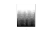
By the way, as described above, when there is sensitivity unevenness between adjacent parts on the
すなわち、シンチレーター3に感度ムラがあり、仮に被写体を介在させない状態で放射線画像撮影装置に対して一様に放射線を照射して、放射線画像を撮影した場合に、例えば図13に示すように、放射線画像p上に濃淡がグラデーション状に現れる場合がある。なお、図13では濃淡が強調されて表されている。また、放射線画像撮影装置に対して一様に放射線を照射して撮影しても、例えば放射線画像pの中央部分が明るく、周縁部分が暗く撮影されるような場合もある。
That is, when the
このような場合、放射線画像pの近接部分同士の濃淡が大きく変化しているわけではないため、画像ムラとしては視認されないが、放射線画像pのある部分が他の部分に比べて暗く見えるため、放射線画像pが見づらくなる可能性がある。 In such a case, since the shade between adjacent portions of the radiographic image p does not change greatly, it is not visually recognized as image unevenness, but a portion of the radiographic image p looks darker than other portions, The radiation image p may be difficult to see.
そこで、例えば、前述した本発明に係る各処理と並行して、上記のようにして算出、更新した放射線画像撮影装置1の検出部Pの各領域Rnごとの累積被曝線量Σdstの中から最大値と最小値を抽出してそれらの差を算出したり、或いは各領域Rnごとの累積被曝線量Σdstの平均値を算出してその平均値と最大値や最小値とを比較するように構成し、最大値と最小値との差が所定の閾値以上に大きい場合や、最大値と平均値との差或いは平均値と最小値との差が所定の閾値以上に大きい場合には、シンチレーター3の各部分に比較的大きな感度ムラが生じており、放射線画像p上に濃淡がグラデーション状に現れる可能性があると判断して、当該放射線画像撮影装置1についてゲインキャリブレーションの実行を促す報知を行うように構成することが可能である。
Therefore, for example, in parallel with each process according to the present invention described above, the maximum value is calculated from the cumulative exposure doses Σdst for each region Rn of the detection unit P calculated and updated as described above. And extracting the minimum value and calculating the difference between them, or calculating the average value of the cumulative exposure dose Σdst for each region Rn and comparing the average value with the maximum and minimum values, When the difference between the maximum value and the minimum value is larger than a predetermined threshold value, or when the difference between the maximum value and the average value or the difference between the average value and the minimum value is larger than a predetermined threshold value, each of the
このように構成すれば、シンチレーター3の各部分に比較的大きな感度ムラが生じており、放射線画像p上に濃淡がグラデーション状に現れる可能性があるような場合に、放射線画像撮影装置1についてゲインキャリブレーションを実行させて、シンチレーター3の各部分の感度ムラに起因して放射線画像p上に濃淡がグラデーション状に現れることを的確に防止することが可能となる。
With this configuration, relatively large sensitivity unevenness occurs in each part of the
なお、本発明が上記の実施例等に限定されず、本発明の趣旨を逸脱しない限り、適宜変更可能であることは言うまでもない。 Needless to say, the present invention is not limited to the above-described embodiments and the like, and can be appropriately changed without departing from the gist of the present invention.
1 放射線画像撮影装置
3 シンチレーター
7 放射線検出素子
22 制御手段(更新手段、算出手段、判断手段、報知手段)
23 記憶手段
58 コンソール(コンピューター)
58A CPU(更新手段、算出手段、判断手段、報知手段)
58C メモリー(記憶手段)
100 放射線画像撮影システム
d 被曝線量
Dlag ラグの信号値
Dlag_st ラグの信号値の統計値
dst 被曝線量の統計値
Rn 領域
|ΔΣdst| 差分の絶対値
|ΔΣdst|max 差分の絶対値の最大値
ΔΣdth 閾値
Σdst 累積被曝線量
ΣΔdst 累積値
ΣΔdth 閾値
DESCRIPTION OF
23 storage means 58 console (computer)
58A CPU (update means, calculation means, judgment means, notification means)
58C memory (storage means)
100 Radiation imaging system d Exposure dose Dlag Lag signal value Dlag_st Lag signal value statistical value dst Exposure dose statistical value Rn Region | ΔΣdst | Difference absolute value | ΔΣdst | max Maximum absolute difference value ΔΣdth threshold Σdst Cumulative dose ΣΔdst Cumulative value ΣΔdth threshold
Claims (9)
前記放射線画像撮影装置の二次元状に配列された複数の前記放射線検出素子を仮想的に複数の領域に分割した場合の前記領域ごとに、前記放射線画像撮影装置で撮影後に放射線が照射されない状態で前記放射線検出素子ごとに取得された、照射線量に起因するラグの信号値の統計値を算出し、算出した前記領域ごとの前記ラグの信号値の統計値に基づいて当該領域における被曝線量の統計値を算出して、前記領域ごとに、算出した前記被曝線量の統計値を、過去に算出した被曝線量の統計値の積算値である累積被曝線量に加算して、前記領域ごとの累積被曝線量を更新する更新手段と、
更新された前記領域ごとの累積被曝線量を記憶する記憶手段と、
前記領域同士の前記累積被曝線量の差分の絶対値を算出する算出手段と、
算出された前記差分の絶対値の中に、設定された閾値以上の差分の絶対値が存在するか否かを判断する判断手段と、
前記判断手段により、前記差分の絶対値の中に前記閾値以上の差分の絶対値が存在すると判断された場合に、当該放射線画像撮影装置についてゲインキャリブレーションの実行を促す報知を行う報知手段と、
を備えることを特徴とする放射線画像撮影システム。 A radiographic imaging apparatus comprising a scintillator and a plurality of radiation detection elements arranged two-dimensionally;
In a state where radiation is not irradiated after imaging by the radiographic imaging device for each of the regions when the plurality of the radiation detection elements arranged in a two-dimensional array of the radiographic imaging device are virtually divided into a plurality of regions. The statistical value of the signal value of the lag caused by the irradiation dose obtained for each of the radiation detection elements is calculated, and the statistical value of the exposure dose in the region based on the statistical value of the signal value of the lag for each of the calculated regions A value is calculated, and for each region, the calculated statistical value of the radiation dose is added to a cumulative radiation dose that is an integrated value of statistical values of the radiation dose calculated in the past, and a cumulative radiation dose for each region is calculated. Updating means for updating
Storage means for storing the cumulative exposure dose for each of the updated areas;
A calculating means for calculating an absolute value of a difference between the accumulated doses between the regions;
A judging means for judging whether or not an absolute value of a difference equal to or larger than a set threshold exists in the calculated absolute value of the difference;
An informing means for informing the radiographic imaging apparatus to execute gain calibration when the determining means determines that the absolute value of the difference equal to or greater than the threshold is present in the absolute value of the difference;
A radiographic imaging system comprising:
前記判断手段および前記報知手段は、前記放射線画像撮影装置以外のコンピューターが備えており、
前記放射線画像撮影装置の前記算出手段は、前記領域ごとに算出した前記差分の絶対値の中から最大値を抽出して前記コンピューターに送信し、
前記コンピューターの前記判断手段は、送信されてきた前記差分の絶対値に基づいて処理を行うことを特徴とする請求項1から請求項3のいずれか一項に記載の放射線画像撮影システム。 The update means, the storage means, and the calculation means are provided in the radiographic imaging device,
The determination means and the notification means are provided in a computer other than the radiographic imaging device,
The calculation means of the radiographic image capturing apparatus extracts the maximum value from the absolute value of the difference calculated for each region and transmits it to the computer,
The radiographic imaging system according to claim 1, wherein the determination unit of the computer performs processing based on an absolute value of the transmitted difference.
前記放射線画像撮影装置の二次元状に配列された複数の前記放射線検出素子を仮想的に複数の領域に分割した場合の前記領域ごとに、前記放射線画像撮影装置で撮影後に放射線が照射されない状態で前記放射線検出素子ごとに取得された、照射線量に起因するラグの信号値の統計値を算出し、算出した前記領域ごとの前記ラグの信号値の統計値に基づいて当該領域における被曝線量の統計値を算出する算出手段と、
前記領域同士の前記被曝線量の統計値の差分を算出し、算出した前記領域同士の被曝線量の統計値の差分を、過去に算出した前記領域同士の被曝線量の統計値の差分の累積値に加算して、前記領域同士の被曝線量の統計値の差分の累積値を更新する更新手段と、
更新された前記領域同士の被曝線量の統計値の差分の累積値を記憶する記憶手段と、
前記領域同士の被曝線量の統計値の差分の累積値の中に、その絶対値が、設定された閾値以上の差分の累積値が存在するか否かを判断する判断手段と、
前記判断手段により、前記差分の累積値の中に、その絶対値が前記閾値以上の差分の累積値が存在すると判断された場合に、当該放射線画像撮影装置についてゲインキャリブレーションの実行を促す報知を行う報知手段と、
を備えることを特徴とする放射線画像撮影システム。 A radiographic imaging apparatus comprising a scintillator and a plurality of radiation detection elements arranged two-dimensionally;
In a state where radiation is not irradiated after imaging by the radiographic imaging device for each of the regions when the plurality of the radiation detection elements arranged in a two-dimensional array of the radiographic imaging device are virtually divided into a plurality of regions. The statistical value of the signal value of the lag caused by the irradiation dose obtained for each of the radiation detection elements is calculated, and the statistical value of the exposure dose in the region based on the statistical value of the signal value of the lag for each of the calculated regions A calculating means for calculating a value;
The difference in the statistical value of the exposure dose between the areas is calculated, and the difference in the statistical value of the exposure dose between the calculated areas is set to the cumulative value of the difference in the statistical value of the exposure dose between the areas calculated in the past. In addition, update means for updating the cumulative value of the difference in the statistical value of the exposure dose between the regions,
Storage means for storing a cumulative value of a difference in statistical values of exposure dose between the updated areas;
In the cumulative value of the difference between the statistical values of the exposure dose between the regions, a determination means for determining whether or not the absolute value of the cumulative value of the difference equal to or more than a set threshold exists,
When the determination means determines that a cumulative value of a difference whose absolute value is greater than or equal to the threshold value is present in the cumulative value of the difference, a notification that prompts execution of gain calibration for the radiographic imaging device Notification means to perform;
A radiographic imaging system comprising:
前記判断手段および前記報知手段は、前記放射線画像撮影装置以外のコンピューターが備えていることを特徴とする請求項1から請求項6のいずれか一項に記載の放射線画像撮影システム。 The update means, the storage means, and the calculation means are provided in the radiographic imaging device,
The radiographic imaging system according to claim 1, wherein the determination unit and the notification unit are provided in a computer other than the radiographic imaging device.
二次元状に配列された複数の前記放射線検出素子を仮想的に複数の領域に分割した場合の前記領域ごとに、撮影後に放射線が照射されない状態で前記放射線検出素子ごとに取得された、照射線量に起因するラグの信号値の統計値を算出し、算出した前記領域ごとの前記ラグの信号値の統計値に基づいて当該領域における被曝線量の統計値を算出して、前記領域ごとに、算出した前記被曝線量の統計値を、過去に算出した被曝線量の統計値の積算値である累積被曝線量に加算して、前記領域ごとの累積被曝線量を更新する更新手段と、
更新された前記領域ごとの累積被曝線量を記憶する記憶手段と、
前記領域同士の前記累積被曝線量の差分の絶対値を算出する算出手段と、
算出された前記差分の絶対値の中に、設定された閾値以上の差分の絶対値が存在するか否かを判断する判断手段と、
前記判断手段により、前記差分の絶対値の中に前記閾値以上の差分の絶対値が存在すると判断された場合に、ゲインキャリブレーションの実行を促す報知を行う報知手段と、
を備えることを特徴とする放射線画像撮影装置。 In a radiographic imaging apparatus including a scintillator and a plurality of radiation detection elements arranged in a two-dimensional shape,
Irradiation dose acquired for each of the radiation detection elements in a state in which radiation is not irradiated after imaging for each of the regions when the plurality of radiation detection elements arranged in a two-dimensional manner are virtually divided into a plurality of regions. Calculate the statistical value of the lag signal value due to the above, calculate the statistical value of the exposure dose in the region based on the calculated statistical value of the lag signal value for each region, and calculate for each region Updating means for adding the statistical value of the exposure dose to the cumulative exposure dose that is an integrated value of the statistical values of the exposure dose calculated in the past, and updating the cumulative exposure dose for each region;
Storage means for storing the cumulative exposure dose for each of the updated areas;
A calculating means for calculating an absolute value of a difference between the accumulated doses between the regions;
A judging means for judging whether or not an absolute value of a difference equal to or larger than a set threshold exists in the calculated absolute value of the difference;
An informing means for informing the execution of gain calibration when the determining means determines that the absolute value of the difference equal to or greater than the threshold exists in the absolute value of the difference;
A radiographic imaging apparatus comprising:
二次元状に配列された複数の前記放射線検出素子を仮想的に複数の領域に分割した場合の前記領域ごとに、撮影後に放射線が照射されない状態で前記放射線検出素子ごとに取得された、照射線量に起因するラグの信号値の統計値を算出し、算出した前記領域ごとの前記ラグの信号値の統計値に基づいて当該領域における被曝線量の統計値を算出する算出手段と、
前記領域同士の前記被曝線量の統計値の差分を算出し、算出した前記領域同士の被曝線量の統計値の差分を、過去に算出した前記領域同士の被曝線量の統計値の差分の累積値に加算して、前記領域同士の被曝線量の統計値の差分の累積値を更新する更新手段と、
更新された前記領域同士の被曝線量の統計値の差分の累積値を記憶する記憶手段と、
前記領域同士の被曝線量の統計値の差分の累積値の中に、その絶対値が、設定された閾値以上の差分の累積値が存在するか否かを判断する判断手段と、
前記判断手段により、前記差分の累積値の中に、その絶対値が前記閾値以上の差分の累積値が存在すると判断された場合に、ゲインキャリブレーションの実行を促す報知を行う報知手段と、
を備えることを特徴とする放射線画像撮影装置。 In a radiographic imaging apparatus including a scintillator and a plurality of radiation detection elements arranged in a two-dimensional shape,
Irradiation dose acquired for each of the radiation detection elements in a state in which radiation is not irradiated after imaging for each of the regions when the plurality of radiation detection elements arranged in a two-dimensional manner are virtually divided into a plurality of regions. Calculating a statistic value of the signal value of the lag caused by the calculation, and calculating a statistical value of the exposure dose in the region based on the calculated statistical value of the signal value of the lag for each region,
The difference in the statistical value of the exposure dose between the areas is calculated, and the difference in the statistical value of the exposure dose between the calculated areas is set to the cumulative value of the difference in the statistical value of the exposure dose between the areas calculated in the past. In addition, update means for updating the cumulative value of the difference in the statistical value of the exposure dose between the regions,
Storage means for storing a cumulative value of a difference in statistical values of exposure dose between the updated areas;
In the cumulative value of the difference between the statistical values of the exposure dose between the regions, a determination means for determining whether or not the absolute value of the cumulative value of the difference equal to or more than a set threshold exists,
Informing means for informing the execution of gain calibration when the judging means judges that the accumulated value of the difference includes the accumulated value of the difference whose absolute value is equal to or greater than the threshold value;
A radiographic imaging apparatus comprising:
Priority Applications (1)
| Application Number | Priority Date | Filing Date | Title |
|---|---|---|---|
| JP2015127260A JP6455337B2 (en) | 2015-06-25 | 2015-06-25 | Radiographic imaging system and radiographic imaging device |
Applications Claiming Priority (1)
| Application Number | Priority Date | Filing Date | Title |
|---|---|---|---|
| JP2015127260A JP6455337B2 (en) | 2015-06-25 | 2015-06-25 | Radiographic imaging system and radiographic imaging device |
Publications (2)
| Publication Number | Publication Date |
|---|---|
| JP2017006503A true JP2017006503A (en) | 2017-01-12 |
| JP6455337B2 JP6455337B2 (en) | 2019-01-23 |
Family
ID=57760718
Family Applications (1)
| Application Number | Title | Priority Date | Filing Date |
|---|---|---|---|
| JP2015127260A Active JP6455337B2 (en) | 2015-06-25 | 2015-06-25 | Radiographic imaging system and radiographic imaging device |
Country Status (1)
| Country | Link |
|---|---|
| JP (1) | JP6455337B2 (en) |
Cited By (2)
| Publication number | Priority date | Publication date | Assignee | Title |
|---|---|---|---|---|
| CN108852401A (en) * | 2018-07-11 | 2018-11-23 | 上海联影医疗科技有限公司 | A kind of correction table creation method, device, CT system and storage medium |
| JP2018192056A (en) * | 2017-05-18 | 2018-12-06 | 富士フイルム株式会社 | Radiation image capturing apparatus, image processing apparatus, image processing method, and image processing program |
Citations (7)
| Publication number | Priority date | Publication date | Assignee | Title |
|---|---|---|---|---|
| JP2005308600A (en) * | 2004-04-23 | 2005-11-04 | Shimadzu Corp | Radiation foreign matter inspection equipment |
| US20090010391A1 (en) * | 2007-07-06 | 2009-01-08 | Fujifilm Corporation | Radiation Image Capturing System |
| JP2009034484A (en) * | 2007-07-06 | 2009-02-19 | Fujifilm Corp | Radiation imaging system |
| US20100061616A1 (en) * | 2008-09-08 | 2010-03-11 | Fujifilm Corporation | Management device, storage medium stored with program and imaging device |
| JP2011045492A (en) * | 2009-08-26 | 2011-03-10 | Canon Inc | Imaging system, image processing method therefor and program therefor |
| JP2011156241A (en) * | 2010-02-03 | 2011-08-18 | Konica Minolta Medical & Graphic Inc | Radiographic imaging device, and radiographic imaging system |
| JP2012159497A (en) * | 2011-01-11 | 2012-08-23 | Toshiba Corp | X-ray diagnostic device |
-
2015
- 2015-06-25 JP JP2015127260A patent/JP6455337B2/en active Active
Patent Citations (9)
| Publication number | Priority date | Publication date | Assignee | Title |
|---|---|---|---|---|
| JP2005308600A (en) * | 2004-04-23 | 2005-11-04 | Shimadzu Corp | Radiation foreign matter inspection equipment |
| US20090010391A1 (en) * | 2007-07-06 | 2009-01-08 | Fujifilm Corporation | Radiation Image Capturing System |
| JP2009034484A (en) * | 2007-07-06 | 2009-02-19 | Fujifilm Corp | Radiation imaging system |
| US20100061616A1 (en) * | 2008-09-08 | 2010-03-11 | Fujifilm Corporation | Management device, storage medium stored with program and imaging device |
| JP2010082426A (en) * | 2008-09-08 | 2010-04-15 | Fujifilm Corp | Management device, program and imaging device |
| JP2011045492A (en) * | 2009-08-26 | 2011-03-10 | Canon Inc | Imaging system, image processing method therefor and program therefor |
| JP2011156241A (en) * | 2010-02-03 | 2011-08-18 | Konica Minolta Medical & Graphic Inc | Radiographic imaging device, and radiographic imaging system |
| JP2012159497A (en) * | 2011-01-11 | 2012-08-23 | Toshiba Corp | X-ray diagnostic device |
| US20130121466A1 (en) * | 2011-01-11 | 2013-05-16 | Takeo Matsuzaki | X-ray diagnostic apparatus |
Cited By (3)
| Publication number | Priority date | Publication date | Assignee | Title |
|---|---|---|---|---|
| JP2018192056A (en) * | 2017-05-18 | 2018-12-06 | 富士フイルム株式会社 | Radiation image capturing apparatus, image processing apparatus, image processing method, and image processing program |
| CN108852401A (en) * | 2018-07-11 | 2018-11-23 | 上海联影医疗科技有限公司 | A kind of correction table creation method, device, CT system and storage medium |
| CN108852401B (en) * | 2018-07-11 | 2022-04-15 | 上海联影医疗科技股份有限公司 | A correction table generation method, device, CT system and storage medium |
Also Published As
| Publication number | Publication date |
|---|---|
| JP6455337B2 (en) | 2019-01-23 |
Similar Documents
| Publication | Publication Date | Title |
|---|---|---|
| JP6056380B2 (en) | Radiation imaging system | |
| US8894280B2 (en) | Calibration and correction procedures for digital radiography detectors supporting multiple capture modes, methods and systems for same | |
| JP6763185B2 (en) | Radiation imaging equipment and radiation imaging system | |
| US20130068955A1 (en) | Control device for radiation imaging apparatus and control method therefor | |
| US20130341525A1 (en) | Radiation image capturing apparatus and radiation image capturing system | |
| JP2017185127A (en) | Radiation ray image photographing system | |
| JP2017099784A (en) | Radiographic apparatus and radiographic system | |
| JP5799725B2 (en) | Radiographic imaging system and radiographic imaging device | |
| JP2020031961A (en) | Radiation imaging system | |
| JP5849646B2 (en) | Radiographic imaging system and radiographic imaging device | |
| JP2013141484A (en) | Radiographic imaging system | |
| JP2013085632A (en) | Radiographic imaging system, image processing apparatus and radiographic imaging apparatus | |
| JP6455337B2 (en) | Radiographic imaging system and radiographic imaging device | |
| JP5428751B2 (en) | Image processing apparatus and image processing system | |
| JP2011117930A (en) | Radiation image forming device and radiation image forming method | |
| JP5799750B2 (en) | Radiographic imaging system and radiographic imaging device | |
| JP2015213546A (en) | Radiation imaging apparatus and radiation imaging system | |
| JP2014216820A (en) | Radiation image photographing system and radiation image photographing device | |
| US20170303885A1 (en) | Radiographic capturing apparatus and radiographic capturing system | |
| JP6142758B2 (en) | Radiographic imaging apparatus and radiographic imaging system | |
| JP7000728B2 (en) | Radiation imaging equipment and radiation imaging system | |
| JP2011160816A (en) | Method for generating image using radiation image detector, radiation image detector, and radiation image generation system | |
| JP2017217171A (en) | Radiographic imaging apparatus and radiographic imaging system | |
| JP2017192605A (en) | Radiographic image capturing system and radiographic image capturing apparatus | |
| JP2013022044A (en) | Radiation imaging system and radiation imaging apparatus |
Legal Events
| Date | Code | Title | Description |
|---|---|---|---|
| A621 | Written request for application examination |
Free format text: JAPANESE INTERMEDIATE CODE: A621 Effective date: 20171225 |
|
| A977 | Report on retrieval |
Free format text: JAPANESE INTERMEDIATE CODE: A971007 Effective date: 20181029 |
|
| TRDD | Decision of grant or rejection written | ||
| A01 | Written decision to grant a patent or to grant a registration (utility model) |
Free format text: JAPANESE INTERMEDIATE CODE: A01 Effective date: 20181120 |
|
| A61 | First payment of annual fees (during grant procedure) |
Free format text: JAPANESE INTERMEDIATE CODE: A61 Effective date: 20181203 |
|
| R150 | Certificate of patent or registration of utility model |
Ref document number: 6455337 Country of ref document: JP Free format text: JAPANESE INTERMEDIATE CODE: R150 |