JP2016524699A - Method for determining position-location using a high reliability range and related systems and devices - Google Patents
Method for determining position-location using a high reliability range and related systems and devices Download PDFInfo
- Publication number
- JP2016524699A JP2016524699A JP2016513061A JP2016513061A JP2016524699A JP 2016524699 A JP2016524699 A JP 2016524699A JP 2016513061 A JP2016513061 A JP 2016513061A JP 2016513061 A JP2016513061 A JP 2016513061A JP 2016524699 A JP2016524699 A JP 2016524699A
- Authority
- JP
- Japan
- Prior art keywords
- range
- user device
- circle
- wireless user
- location
- Prior art date
- Legal status (The legal status is an assumption and is not a legal conclusion. Google has not performed a legal analysis and makes no representation as to the accuracy of the status listed.)
- Withdrawn
Links
Images


Classifications
-
- G—PHYSICS
- G01—MEASURING; TESTING
- G01S—RADIO DIRECTION-FINDING; RADIO NAVIGATION; DETERMINING DISTANCE OR VELOCITY BY USE OF RADIO WAVES; LOCATING OR PRESENCE-DETECTING BY USE OF THE REFLECTION OR RERADIATION OF RADIO WAVES; ANALOGOUS ARRANGEMENTS USING OTHER WAVES
- G01S19/00—Satellite radio beacon positioning systems; Determining position, velocity or attitude using signals transmitted by such systems
- G01S19/38—Determining a navigation solution using signals transmitted by a satellite radio beacon positioning system
- G01S19/39—Determining a navigation solution using signals transmitted by a satellite radio beacon positioning system the satellite radio beacon positioning system transmitting time-stamped messages, e.g. GPS [Global Positioning System], GLONASS [Global Orbiting Navigation Satellite System] or GALILEO
- G01S19/42—Determining position
- G01S19/45—Determining position by combining measurements of signals from the satellite radio beacon positioning system with a supplementary measurement
- G01S19/46—Determining position by combining measurements of signals from the satellite radio beacon positioning system with a supplementary measurement the supplementary measurement being of a radio-wave signal type
-
- G—PHYSICS
- G01—MEASURING; TESTING
- G01S—RADIO DIRECTION-FINDING; RADIO NAVIGATION; DETERMINING DISTANCE OR VELOCITY BY USE OF RADIO WAVES; LOCATING OR PRESENCE-DETECTING BY USE OF THE REFLECTION OR RERADIATION OF RADIO WAVES; ANALOGOUS ARRANGEMENTS USING OTHER WAVES
- G01S19/00—Satellite radio beacon positioning systems; Determining position, velocity or attitude using signals transmitted by such systems
- G01S19/38—Determining a navigation solution using signals transmitted by a satellite radio beacon positioning system
- G01S19/39—Determining a navigation solution using signals transmitted by a satellite radio beacon positioning system the satellite radio beacon positioning system transmitting time-stamped messages, e.g. GPS [Global Positioning System], GLONASS [Global Orbiting Navigation Satellite System] or GALILEO
- G01S19/396—Determining accuracy or reliability of position or pseudorange measurements
-
- G—PHYSICS
- G01—MEASURING; TESTING
- G01S—RADIO DIRECTION-FINDING; RADIO NAVIGATION; DETERMINING DISTANCE OR VELOCITY BY USE OF RADIO WAVES; LOCATING OR PRESENCE-DETECTING BY USE OF THE REFLECTION OR RERADIATION OF RADIO WAVES; ANALOGOUS ARRANGEMENTS USING OTHER WAVES
- G01S5/00—Position-fixing by co-ordinating two or more direction or position line determinations; Position-fixing by co-ordinating two or more distance determinations
- G01S5/02—Position-fixing by co-ordinating two or more direction or position line determinations; Position-fixing by co-ordinating two or more distance determinations using radio waves
- G01S5/14—Determining absolute distances from a plurality of spaced points of known location
Landscapes
- Engineering & Computer Science (AREA)
- Radar, Positioning & Navigation (AREA)
- Remote Sensing (AREA)
- Physics & Mathematics (AREA)
- General Physics & Mathematics (AREA)
- Computer Networks & Wireless Communication (AREA)
- Position Fixing By Use Of Radio Waves (AREA)
- Mobile Radio Communication Systems (AREA)
- Telephone Function (AREA)
- Telephonic Communication Services (AREA)
Abstract
位置−場所を求める方法が提供される。その方法は高信頼度の第1の測距源からのシグナリングを用いて、ワイヤレスユーザデバイスのための第1の範囲を求めることを含むことができる。その方法は、高信頼度の第1の測距源より低い信頼度に対応する第2の測距源からのシグナリングを用いて、ワイヤレスユーザデバイスのための第2の範囲を求めることを含むことができる。さらに、その方法は、第1の範囲に基づいて画定された第1の幾何学的形状を用いることによってワイヤレスユーザデバイスの位置−場所を求めることを含むことができる。関連するワイヤレスユーザデバイス並びに中央システム及び/又は中央デバイスも記述される。【選択図】図1AA method for determining position-location is provided. The method can include determining a first range for a wireless user device using signaling from a reliable first ranging source. The method includes determining a second range for the wireless user device using signaling from a second ranging source that corresponds to a lower reliability than the first reliable ranging source. Can do. Further, the method can include determining a position-location of the wireless user device by using a first geometry defined based on the first range. Related wireless user devices and central systems and / or central devices are also described. [Selection] Figure 1A
Description
本開示はワイヤレス通信方法、システム及びデバイスに関し、より詳細には、位置場所を求める方法、システム及びデバイスに関する。 The present disclosure relates to wireless communication methods, systems and devices, and more particularly to methods, systems and devices for determining location locations.
[優先権の主張]
本出願は、2013年5月10日に出願された「Methods of Position-Location Determination Using a High-Confidence Range Calculation」と題する米国仮特許出願第61/821,871号の利益を主張する。この特許文献の開示は引用することによりその全体が本明細書の一部をなすものとする。
[Priority claim]
This application claims the benefit of US Provisional Patent Application No. 61 / 821,871, filed May 10, 2013, entitled “Methods of Position-Location Determination Using a High-Confidence Range Calculation”. The disclosure of this patent document is incorporated herein by reference in its entirety.
位置特定システム(PLS)の例は、グローバルポジショニングシステム(GPS)、Wi−Fi、アシスト型GPS(例えば、携帯電話基地局を使用する)、及び/又は地上ビーコンネットワーク(TBN:Terrestrial Beacon Network)システムを含む。これらのシステムは、位置−場所を求めるための種々の精度を提供することができる。例えば、GPSは、上空が見通せる条件(open-sky condition)下で高い精度を有することができるが、ビルの谷間又は建物内ではあまり使用に適さない場合がある。同様に、ロングタームエボリューション(LTE)に基づく位置は、サービングセルの非常に良好な位置決定を提供することができるが、隣接するセルからの測距の場合にあまり精度が高くない場合がある。さらに、TBNは複数のビーコンからの測距誤差を有する場合があり、TBNでは、信号対雑音比(SNR)、相関ピークのパルス形状、及び/又は何らかの事前決定(a priori determination)に基づいて、ビーコンのうちの1つからの信頼度は非常に高い(例えば、範囲の判断が正確である)場合があるが、1組の他のビーコンからの信頼度は低い場合がある。 Examples of location systems (PLS) include global positioning system (GPS), Wi-Fi, assisted GPS (eg, using a mobile phone base station), and / or a terrestrial beacon network (TBN) system. including. These systems can provide various accuracies for determining position-location. For example, GPS may have high accuracy under open-sky conditions, but may not be well suited for use in building valleys or buildings. Similarly, location based on long term evolution (LTE) can provide very good positioning of the serving cell, but may not be very accurate in the case of ranging from neighboring cells. In addition, the TBN may have ranging errors from multiple beacons, where the TBN is based on signal-to-noise ratio (SNR), correlation peak pulse shape, and / or some a priori determination, The reliability from one of the beacons may be very high (eg, the range determination is accurate), but the reliability from one set of other beacons may be low.
幾つかの実施形態によれば、位置−場所を求める方法が提供される。その方法は、高信頼度の第1の測距源からのシグナリングを用いてワイヤレスユーザデバイスのための第1の範囲を求めることを含むことができる。その方法は、高信頼度の第1の測距源より低い信頼度に対応する第2の測距源からのシグナリングを用いて、ワイヤレスユーザデバイスのための第2の範囲を求めることを含むことができる(それゆえ、第2の範囲は、第1の範囲より低い信頼度に対応することができる)。その方法は、第1の範囲及び第2の範囲に基づいてそれぞれ画定される第1の幾何学的形状及び第2の幾何学的形状が交差するか否かを判断することを含むことができる。その方法は、第3の測距源からのシグナリングを用いて、ワイヤレスユーザデバイスのための第3の範囲を求めることを含むことができる。さらに、その方法は、第3の範囲を用いて第1の幾何学的形状の外周に沿った位置を示すことによって、ワイヤレスユーザデバイスの位置−場所を求めることを含むことができる。その方法を実行するように構成されるワイヤレスユーザデバイス、中央デバイス及び/又は中央システムも提供することができる。 According to some embodiments, a method for determining position-location is provided. The method can include determining a first range for a wireless user device using signaling from a reliable first ranging source. The method includes determining a second range for the wireless user device using signaling from a second ranging source that corresponds to a lower reliability than the first reliable ranging source. (Hence, the second range can correspond to a lower reliability than the first range). The method can include determining whether a first geometric shape and a second geometric shape defined based on the first range and the second range, respectively, intersect. . The method can include determining a third range for the wireless user device using signaling from a third ranging source. Further, the method can include determining a position-location of the wireless user device by indicating a position along the outer periphery of the first geometry using the third range. A wireless user device, central device and / or central system configured to perform the method may also be provided.
幾つかの実施形態では、その方法は、第1の幾何学的形状及び第2の幾何学的形状が交差しないと判断することに応答して、第2の範囲を調整することを含むことができる。幾つかの実施形態では、その方法は、第2の範囲を調整する前に、ワイヤレスユーザデバイスの位置−場所を推定することを含むことができ、ワイヤレスユーザデバイスの位置−場所を求めることは、第2の範囲に対する調整(例えば、第2の範囲の射影)を用いて、第1の幾何学的形状の外周上の位置を示すことを含むことができる。さらに、第2の範囲を調整することは、第1の幾何学的形状及び第2の幾何学的形状が交差しないと判断することに応答して、第2の範囲を、高信頼度の第1の測距源の第1の範囲に基づいて画定された第1の幾何学的形状上に射影することを含むことができる。第1の幾何学的形状及び第2の幾何学的形状はそれぞれ、交差しない第1の円及び第2の円を含むことができ、第2の範囲を射影することは、第2の円の外周が第1の円の外周上にあるように、第2の円の半径を増加又は減少させることを含むことができる。さらに、第1の範囲は、第1の測距源とワイヤレスユーザデバイスとの間の距離を示すことができ、第1の範囲は第1の円の半径を規定することができる。 In some embodiments, the method can include adjusting the second range in response to determining that the first geometric shape and the second geometric shape do not intersect. it can. In some embodiments, the method can include estimating the location-location of the wireless user device before adjusting the second range, and determining the location-location of the wireless user device includes: An adjustment to the second range (eg, a projection of the second range) may be used to indicate the position on the outer periphery of the first geometric shape. Further, adjusting the second range is responsive to determining that the first geometric shape and the second geometric shape do not intersect the second range, Projecting onto a first geometric shape defined based on a first range of one ranging source may be included. The first geometric shape and the second geometric shape can include a first circle and a second circle, respectively, that do not intersect, and projecting the second range is the second circle's Increasing or decreasing the radius of the second circle may be included so that the outer periphery is on the outer periphery of the first circle. Further, the first range can indicate a distance between the first ranging source and the wireless user device, and the first range can define a radius of the first circle.
幾つかの実施形態では、ワイヤレスユーザデバイスの位置−場所を求めることは、第1の幾何学的形状及び第2の幾何学的形状が交差するか否かを判断した後に、第3の範囲を用いて第1の幾何学的形状の外周に沿った位置を示すことによって、ワイヤレスユーザデバイスの位置−場所を求めることを含むことができる。さらに、第3の測距源は、第2の測距源より高い信頼度及び/又は高い精度に対応することができる(それゆえ、第3の範囲は、第2の範囲より高い信頼度及び/又は高い精度に対応することができる)。 In some embodiments, determining the location-location of the wireless user device may include determining the third range after determining whether the first geometry and the second geometry intersect. Determining the position-location of the wireless user device by using to indicate a position along the outer periphery of the first geometry may be included. Further, the third ranging source can correspond to higher reliability and / or higher accuracy than the second ranging source (thus, the third range is higher in reliability and / or higher than the second range). And / or high accuracy).
幾つかの実施形態では、第1の測距源及び第2の測距源はそれぞれ、異なる位置特定システムに属する(すなわち、異なる位置特定システムの一部分となる)ことができる。異なる位置特定システムはいずれも同じタイプの位置特定システムである(例えば、グローバルポジショニングシステム(GPS)、Wi−Fi、セルラ又は地上ビーコンネットワーク(TBN)のうちの同じものとすることができる)。代替的には、異なる位置特定システムは、異なるタイプの位置特定システムとすることができる(例えば、グローバルポジショニングシステム(GPS)、Wi−Fi、セルラ及び地上ビーコンネットワーク(TBN)のうちの異なるものとすることができる)。 In some embodiments, the first ranging source and the second ranging source can each belong to a different location system (ie, become part of a different location system). The different location systems are all the same type of location system (e.g., the same of global positioning system (GPS), Wi-Fi, cellular or terrestrial beacon network (TBN)). Alternatively, the different location systems can be different types of location systems (e.g., different ones of global positioning system (GPS), Wi-Fi, cellular and terrestrial beacon network (TBN)). can do).
幾つかの実施形態では、第1の測距源、第2の測距源及び第3の測距源は、同じ位置特定システムに属する(すなわち、同じ位置特定システムの一部分となる)ことができる。幾つかの実施形態では、第1の範囲及び第2の範囲はそれぞれ第1の範囲計算値及び第2の範囲計算値とすることができ、第1の範囲計算値は第2の範囲計算値より正確であることができる。さらに、第1の範囲を求めることは、受信信号パラメータ、位置特定システムタイプ、測距源高度、ワイヤレスユーザデバイスへの測距源近接度、最も制限された範囲の測距源、最も高い精度の範囲計算値を与える履歴、及び測距源帯域幅のうちの少なくとも1つに基づいて、ワイヤレスユーザデバイスの位置−場所を求める際に(第1の範囲のワイヤレスユーザデバイス又は中央システム/デバイスによって)使用するための高信頼度の第1の測距源を選択することを含むことができる。受信信号パラメータは、受信信号強度、信号対雑音比、及び相関ピークの形状のうちの少なくとも1つを含むことができる。 In some embodiments, the first ranging source, the second ranging source, and the third ranging source can belong to the same location system (ie, become part of the same location system). . In some embodiments, the first range and the second range may be a first range calculated value and a second range calculated value, respectively, and the first range calculated value is a second range calculated value. Can be more accurate. Further, determining the first range includes receiving signal parameters, location system type, ranging source altitude, ranging source proximity to the wireless user device, most limited range ranging source, highest accuracy range. In determining the location-location of a wireless user device based on at least one of a history providing range calculations and a ranging source bandwidth (by the first range wireless user device or central system / device) Selecting a reliable first ranging source for use. The received signal parameters can include at least one of received signal strength, signal to noise ratio, and correlation peak shape.
幾つかの実施形態では、第1の範囲を求めることは、高信頼度の第1の測距源が、複数の測距源の中の最も高い信頼度及び/又は最も高い精度の測距源を含むと判断することを含むことができ、高信頼度の第1の測距源が、複数の測距源の中の最も高い信頼度及び/又は最も高い精度の測距源を含むと判断することに応答して、ワイヤレスユーザデバイスの位置−場所を求める際に(第1の範囲のワイヤレスユーザデバイス又は中央システム/デバイスによって)使用するための高信頼度の第1の測距源を選択することを含むことができる。それに加えて、又はその代わりに、高信頼度の第1の測距源を選択することは、信号品質のしきい値レベルを超える測距源を選択することを含むことができる。 In some embodiments, determining the first range may be that the reliable first ranging source has the highest reliability and / or highest accuracy ranging source among the plurality of ranging sources. And determining that the first reliable ranging source includes the highest reliability and / or highest accuracy ranging source among the plurality of ranging sources. In response to selecting a reliable first ranging source for use (by a first range wireless user device or central system / device) in determining the location-location of the wireless user device. Can include. In addition or alternatively, selecting the first reliable ranging source may include selecting a ranging source that exceeds a threshold level of signal quality.
幾つかの実施形態によれば、位置−場所を求める方法が提供される。その方法は、ワイヤレスユーザデバイスを用いて、高信頼度の第1の測距源からのシグナリングを用いて、ワイヤレスユーザデバイスのための高信頼度の第1の範囲計算値を求めることを含むことができる。その方法は、ワイヤレスユーザデバイスを用いて、高信頼度の第1の測距源より低い信頼度に対応する第2の測距源からのシグナリングを用いて、ワイヤレスユーザデバイスのための第2の範囲計算値を求めることを含むことができる。第1の範囲計算値及び第2の範囲計算値はそれぞれ、第1の円及び第2の円の第1の半径及び第2の半径を規定することができる。その方法は、ワイヤレスユーザデバイスを用いて、第2の半径の端点が第1の円の外周上にあるように第2の半径を増加又は減少させることによって、第2の範囲計算値を第1の円上に射影することを含むことができる。さらに、その方法は、第1の円の外周上の第2の半径の端点を用いることによって、ワイヤレスユーザデバイスの位置−場所を求めることを含むことができる。その方法を実行するように構成されるワイヤレスユーザデバイスも提供することができる。 According to some embodiments, a method for determining position-location is provided. The method includes using the wireless user device to determine a reliable first range calculation for the wireless user device using signaling from the reliable first ranging source. Can do. The method uses a wireless user device to generate a second for a wireless user device using signaling from a second ranging source that corresponds to a lower reliability than the first reliable ranging source. Determining a range calculation value can be included. The first range calculation value and the second range calculation value may define a first radius and a second radius of the first circle and the second circle, respectively. The method uses a wireless user device to increase or decrease the second radius such that the endpoint of the second radius is on the circumference of the first circle, thereby reducing the second range calculation value to the first. Projecting onto a circle of. Further, the method can include determining the location-location of the wireless user device by using an endpoint of the second radius on the circumference of the first circle. A wireless user device configured to perform the method may also be provided.
幾つかの実施形態では、その方法は、ワイヤレスユーザデバイスを用いて、第1の範囲計算値及び第2の範囲計算値にそれぞれ対応する第1の円及び第2の円が交差するか否かを判断することを含むことができる。さらに、第2の範囲計算値を射影することは、第1の範囲計算値及び第2の範囲計算値にそれぞれ対応する第1の円及び第2の円が交差しないと判断することに応答して、第2の半径の端点が第1の円の外周上にあるように、第2の半径を増加又は減少させることによって第2の範囲計算値を第1の円上に射影することを含むことができる。 In some embodiments, the method uses the wireless user device to determine whether the first circle and the second circle corresponding to the first range calculation value and the second range calculation value, respectively, intersect. Can be included. Further, projecting the second range calculation value is responsive to determining that the first circle and the second circle respectively corresponding to the first range calculation value and the second range calculation value do not intersect. Projecting the second range calculation value onto the first circle by increasing or decreasing the second radius so that the end point of the second radius is on the outer circumference of the first circle. be able to.
幾つかの実施形態では、その方法は、ワイヤレスユーザデバイスを用いて、第3の測距源からのシグナリングを用いて、ワイヤレスユーザデバイスのための第3の範囲計算値を求めることを含むことができる。さらに、ワイヤレスユーザデバイスの位置−場所を求めることは、第3の範囲計算値を用いて、第1の円の外周に沿った位置を示すことを含むことができる。 In some embodiments, the method may include using a wireless user device to determine a third range calculation for the wireless user device using signaling from a third ranging source. it can. Further, determining the position-location of the wireless user device can include using a third range calculation to indicate a position along the circumference of the first circle.
幾つかの実施形態によれば、ワイヤレスユーザデバイスが提供される。ワイヤレスユーザデバイスは、高信頼度の第1の測距源からのシグナリングを用いて、ワイヤレスユーザデバイスのための高信頼度の第1の範囲計算値を求めるように構成されるプロセッサを含むことができる。プロセッサは、高信頼度の第1の測距源より低い信頼度に対応する第2の測距源からのシグナリングを用いて、ワイヤレスユーザデバイスのための第2の範囲計算値を求めるように構成することができる。第1の範囲計算値及び第2の範囲計算値はそれぞれ、第1の円及び第2の円の第1の半径及び第2の半径を規定することができる。プロセッサは、第2の半径の端点が第1の円の外周上にあるように第2の半径を増加又は減少させることによって、第2の範囲計算値を第1の円上に射影するように構成することができる。さらに、プロセッサは、第1の円の外周上の第2の半径の端点を用いることによって、ワイヤレスユーザデバイスの位置−場所を求めるように構成することができる。 According to some embodiments, a wireless user device is provided. The wireless user device may include a processor configured to determine a reliable first range calculation for the wireless user device using signaling from the reliable first ranging source. it can. The processor is configured to determine a second range calculation for the wireless user device using signaling from the second ranging source that corresponds to a lower confidence than the first reliable ranging source. can do. The first range calculation value and the second range calculation value may define a first radius and a second radius of the first circle and the second circle, respectively. The processor projects the second range calculation onto the first circle by increasing or decreasing the second radius so that the end point of the second radius is on the outer circumference of the first circle. Can be configured. Further, the processor can be configured to determine the location-location of the wireless user device by using the endpoint of the second radius on the circumference of the first circle.
幾つかの実施形態では、プロセッサは、第1の範囲計算値及び第2の範囲計算値にそれぞれ対応する第1の円及び第2の円が交差するか否かを判断するように構成することができる。さらに、プロセッサは、第1の範囲計算値及び第2の範囲計算値にそれぞれ対応する第1の円及び第2の円が交差しないと判断することに応答して、第2の半径の端点が第1の円の外周上にあるように、第2の半径を増加又は減少させることによって第2の範囲計算値を第1の円上に射影するように構成することができる。 In some embodiments, the processor is configured to determine whether the first circle and the second circle corresponding to the first range calculation value and the second range calculation value respectively intersect. Can do. Further, in response to determining that the first circle and the second circle corresponding to the first range calculation value and the second range calculation value, respectively, do not intersect, the processor determines that the end point of the second radius is The second range calculation can be configured to project onto the first circle by increasing or decreasing the second radius so that it is on the outer circumference of the first circle.
幾つかの実施形態では、プロセッサは、第3の測距源からのシグナリングを用いて、ワイヤレスユーザデバイスのための第3の範囲計算値を求めるように構成することができる。さらに、プロセッサは、第3の範囲計算値を用いて、第1の円の外周に沿った位置を示すことによって、ワイヤレスユーザデバイスの位置−場所を求めるように構成することができる。 In some embodiments, the processor may be configured to determine a third range calculation for the wireless user device using signaling from a third ranging source. Further, the processor can be configured to determine the position-location of the wireless user device by using the third range calculation to indicate a position along the circumference of the first circle.
次に、本発明の概念の例示的な実施形態を、添付の図面を参照して説明する。しかしながら、本発明の概念は様々な異なる形式で実施することができ、本明細書において示される実施形態に限定されるものと解釈されるべきでない。むしろ、これらの実施形態は、本開示が徹底した完全なものとなり、本発明の概念の範囲を当業者に十分に伝えるように提供される。図面において、同様の符号は同様の要素を指す。要素が別の要素に「接続されている」、「結合されている」又は「応じる」と言うとき、その要素はその別の要素に直接接続、結合又は応じることもできるし、介在する要素が存在することもできることが理解されよう。さらに、「接続されている」、「結合されている」又は「応じる」とは、本明細書において用いられるとき、無線で接続、結合又は応答することを含むことができる。 Exemplary embodiments of the inventive concept will now be described with reference to the accompanying drawings. However, the concepts of the present invention can be implemented in a variety of different forms and should not be construed as limited to the embodiments set forth herein. Rather, these embodiments are provided so that this disclosure will be thorough and complete, and will fully convey the scope of the inventive concept to those skilled in the art. In the drawings, like numerals refer to like elements. When an element is said to be “connected”, “coupled” or “responsive” to another element, the element can also be directly connected, coupled or responsive to that other element, It will be understood that it can exist. Further, “connected”, “coupled” or “responding” as used herein can include wirelessly connecting, coupling or responding.
本明細書において用いられる用語は、本発明の概念の特定の実施形態を説明することだけを目的とし、本発明の概念の限定を意図するものではない。本明細書において用いられる場合、特に明示のない限り、数量が特定されていないものは単数及び複数を包含することが意図される。本明細書において用いられる場合、用語「含む(include)」、「備える、含む(comprise)」、「含んでいる(including)」及び/又は「備えている、含んでいる(comprising)」が、述べられている特徴、ステップ、動作、要素、及び/又は構成要素の存在を特定するが、1つ又は複数の他の特徴、ステップ、動作、要素、構成要素、及び/又はそれらの群の存在又は追加を除外しないことが更に理解されよう。本明細書において用いられるとき、「及び/又は」という用語は、関連する列挙された1つ又は複数の項目のうちの任意のもの及びそれらの全ての組み合わせを含む。「/」というシンボルも、「及び/又は」の略記として用いられる。 The terminology used herein is for the purpose of describing particular embodiments of the inventive concepts only and is not intended to be limiting of the inventive concepts. As used herein, unless stated otherwise, what is not specified is intended to include the singular and the plural. As used herein, the terms “include”, “comprise”, “including” and / or “comprising” Identify the presence of the described feature, step, action, element, and / or component, but the presence of one or more other features, steps, actions, elements, components, and / or groups thereof Or it will be further understood that it does not exclude additions. As used herein, the term “and / or” includes any and all combinations of one or more of the associated listed items. The symbol “/” is also used as an abbreviation for “and / or”.
他に規定のない限り、本明細書において用いられる全ての用語(技術用語及び科学用語を含む)は、本発明の概念が属する技術分野の当業者により一般に理解される意味と同じ意味を有する。一般に用いられる辞書において定義される用語等の用語が、関連する技術分野及び本開示での意味と一致する意味を有するものとして解釈されるべきであり、本明細書において、理想化された、又は過度に形式的な意味で明確に定義される場合を除き、そのような意味で解釈されることにはならないことが更に理解されよう。 Unless defined otherwise, all terms used herein (including technical and scientific terms) have the same meaning as commonly understood by one of ordinary skill in the art to which the concepts of the present invention belong. Terms such as those defined in commonly used dictionaries should be construed as having a meaning consistent with the meaning in the relevant technical field and this disclosure, and have been idealized herein, or It will be further understood that it will not be construed in that sense, unless explicitly defined in an overly formal sense.
用語「第1の(first)」及び「第2の(second)」は、種々の要素を述べるために本明細書で使用される場合があるが、これらの要素は、これらの用語によって制限されるべきでないことが理解されるであろう。これらの用語は、1つの要素と別の要素を区別するために使用されるだけである。このため、本発明の概念の教示から逸脱することなく、第1の要素は第2の要素と呼ぶことができ、同様に、第2の要素を第1の要素と呼ぶことができる。 The terms “first” and “second” may be used herein to describe various elements, but these elements are limited by these terms. It will be understood that it should not. These terms are only used to distinguish one element from another. Thus, the first element can be referred to as the second element, and, similarly, the second element can be referred to as the first element, without departing from the teaching of the inventive concept.
本発明の概念は、本発明の概念の実施形態による動作及びデバイス/システムのフローチャートを参照しながら以下に部分的に説明される。フローチャートの1つ又は複数の所与のブロックは、動作及び/又はデバイス/システムへの支援を与える。 The concepts of the present invention are described in part below with reference to operations and device / system flowcharts according to embodiments of the concepts of the present invention. One or more given blocks of the flowchart provide operation and / or assistance to the device / system.
また、幾つかの実施態様では、フローチャートにおいて言及される機能/動作が、フローチャートにおいて言及された順序に反して行われる場合がある。例えば、連続して示される2つのブロックは実際には実質的に同時に実行される場合もあるし、関与する機能/動作によっては、それらのブロックは逆の順序で実行される場合もある。一例として、図5のブロック511の動作は、図5のブロック503〜507の動作の前に行われる場合がある。最後に、1つ又は複数のブロックの機能は、別々にすることができ、及び/又は他のブロックの機能と組み合わせることができる。例えば、ブロック505及び507の動作は、ブロック511の第3の測距源の範囲を高信頼度の測距源の円上に射影するために繰り返すことができる。
Also, in some implementations, the functions / operations referred to in the flowchart may be performed out of the order noted in the flowchart. For example, two blocks shown in succession may actually be executed substantially simultaneously, or depending on the function / operation involved, the blocks may be executed in reverse order. As an example, the operation of
異なるPLSは測距誤差に関して異なる信頼度を有することができる。例えば、完全に同期したLTEネットワークは、サービングセルの範囲を求める際に高い信頼度を有することができるが、SNRが低いことに起因して、隣接するセルに関していかなる測距判断も有しない場合がある。しかしながら、1つの範囲決定しか有しないことは、ユーザ機器(UE)の場所を求めるのに十分でない場合がある。むしろ、UEの場所を求めるために、既知の場所からの3つ以上の範囲決定が必要とされる場合がある。これらの異なるPLSは異なる信頼水準を有する場合がある(あるいは、同じPLSでさえも、異なる信頼水準を有する異なる測距源(ビーコン又は携帯電話基地局等)を有する場合がある)が、本発明の概念の種々の実施形態は、高信頼度範囲計算値を用いて、場合によっては、幾何学的射影(例えば、高信頼度範囲計算値から導出された幾何学的形状上への低信頼度/精度範囲計算値の射影)を用いて、位置場所を求める際の誤差を低減する。 Different PLS can have different confidences for ranging errors. For example, a fully synchronized LTE network may have a high degree of confidence in determining the range of serving cells, but may not have any ranging decisions with respect to neighboring cells due to low SNR. . However, having only one range determination may not be sufficient to determine the location of the user equipment (UE). Rather, more than two range determinations from known locations may be required to determine the UE location. These different PLS may have different confidence levels (or even the same PLS may have different ranging sources with different confidence levels (such as beacons or mobile phone base stations)) Various embodiments of the concept may use high confidence range calculations, and in some cases, geometric projections (eg, low confidence on geometric shapes derived from high confidence range calculations). / Projection of accuracy range calculation value) to reduce the error when finding the location.
例えば、本明細書において説明される動作は、個々の高精度範囲計算値(又は2つの高精度範囲計算値)を低い信頼度が存在する範囲計算値と組み合わせることを含むことができる。これらの範囲計算値は単一のPLSに属する場合もあるし、種々のPLS(例えば、GPS、TBN、携帯電話基地局及びWi−Fiのうちの異なるもの)に属する場合もある。高信頼度範囲計算値、そして場合によって、幾何学的射影を使用する利点は、処理に関する大きな負荷を受けることなく、位置−場所を求める際の誤差を低減することである。 For example, the operations described herein may include combining individual high accuracy range calculations (or two high accuracy range calculations) with range calculations for which low confidence exists. These range calculation values may belong to a single PLS, or may belong to various PLS (for example, different ones of GPS, TBN, mobile phone base station, and Wi-Fi). The advantage of using high confidence range calculations and, in some cases, geometric projections, is to reduce errors in determining position-location without incurring significant processing overhead.
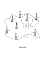
ここで、図1Aを参照すると、地理的エリア102内にUE101が示される。UE101は、種々のタイプのワイヤレス電子ユーザデバイス(モバイル/携帯電話、及び電話機能を持たないワイヤレス電子ユーザデバイスを含む)のうちの1つとすることができる(又はその一部とすることができる)。UE101は、地理的エリア102内のいずれかの場所に位置することができる。図1Aは単一のUE101を示すが、地理的エリア102内に複数のUE101が存在する場合がある。幾つかの実施形態では、地理的エリア102内に数百、数千、又はそれ以上の数のUE101が位置する場合がある。
Referring now to FIG. 1A, a
UE101は、基地局(BS)(例えば、セルラBS)等の送信機から、及び/又は地上ビーコンネットワーク(TBN)のポジショニングビーコン(PB)から信号をワイヤレスで受信することができる。地理的エリア102は、任意の数(例えば、3つ、4つ、数十、又はそれ以上の数)のBS及び/又はPBを含むことができることが理解されよう。さらに、UE101は、地理的エリア102内のWi−Fiホットスポット121から、及び/又はGPSネットワーク174から信号を受信することができる。したがって、BS、PB、Wi−Fiホットスポット121及び/又はGPSネットワーク174への/からの信号を用いて、UE101の場所(例えば、位置)を求めることができる。
The
ここで図1Bを参照すると、測距源T1〜T5はPLSシステムTに属し、測距源A1〜A3はPLSシステムAに属する。具体的には、非限定的な例として、図1Bには2つのPLS T及びAが示される。PLS T及びAは、同じPLSタイプ(TBN等)に属することもできるし、2つの異なるタイプのPLS(GPS及びTBN、TBN及びLTE、TBN及びWi−Fi、又は異なるタイプのPLSの任意の他の組み合わせ等)に属することもできる。一例として、PLSシステムAの測距源A1〜A3はそれぞれ図1AのBS1〜BS3とすることができ、そのBSはLTE基地局とすることができる。同様に、PLSシステムTの測距源T1〜T5はそれぞれ図1AのPB1〜PB5とすることができる。さらに、その組み合わせは、本発明の概念の幾つかの実施形態においては、3つ以上のタイプのPLSシステムを含むことができる。
Referring now to FIG. 1B, ranging sources T 1 -T 5 belong to PLS system T, and ranging sources A 1 -A 3 belong to PLS system A. Specifically, as a non-limiting example, two PLS T and A are shown in FIG. 1B. PLS T and A can belong to the same PLS type (such as TBN), or two different types of PLS (GPS and TBN, TBN and LTE, TBN and Wi-Fi, or any other of different types of PLS) Or the like. As an example, the ranging sources A 1 to A 3 of the PLS system A can be BS 1 to BS 3 in FIG. 1A, respectively, and the BS can be an LTE base station. Similarly, it is possible to distance
本発明の概念の幾つかの実施形態によれば、幾何学的射影(例えば、高信頼度範囲計算値から導出された幾何学的形状上への低信頼度/精度範囲計算値の射影)を用いることなく、又は用いる前に、最初に図1BのUE101の位置を求める/推定することができる。この最初の計算に基づいて、1組の測距源(例えば、測距源T2、T3、T5、A2及びA3を含む1組)からの範囲計算値を選択することができる。さらに、本明細書において説明される範囲計算値は、測距源への及び/又はからの信号を用いて計算された距離を指すことができ、その距離は測距源によって、又はUE101によって計算することができる。
According to some embodiments of the inventive concept, a geometric projection (eg, a projection of a low confidence / accuracy range calculation onto a geometric shape derived from a high confidence range calculation). Without or before use, the location of
ここで図5を参照すると、位置−場所を求める動作のフローチャートが示される。位置−場所を求める動作はブロック500において開始され、UE101によって、及び/又は1組の測距源に関する信号データを受信する中央システム/場所(例えば、UE101から離間して配置される中央デバイス/受信機)において実行することができる。
Referring now to FIG. 5, a flowchart of the operation for determining position-location is shown. The location-location operation begins at
図5を更に参照すると、例えば、信号対雑音比(SNR)、相関ピークの形状、及び/又はUE101が通常位置する地理的エリア102の何らかの事前測定値(複数の場合もある)に基づいて、高い、又は最も高い信頼度/精度の測距源(それゆえ、低い/最も低い誤差を有する範囲計算値)を選択することができる(ブロック501)。高い信頼度/精度の測距源はUE101との通信範囲内にある1組の測距源の中の最も高い信頼度/精度の測距源とすることができ、及び/又は信号品質測定値(複数の場合もある)のしきい値レベルを超える任意の測距源とすることができる。
Still referring to FIG. 5, based on, for example, the signal to noise ratio (SNR), the shape of the correlation peak, and / or some prior measurement (s) of the
例えば、ブロック501の動作は、測距源が複数の測距源の中の最も高い信頼度/精度の測距源であると判断することを含むことができる。さらに、それらの動作は、測距源が複数の測距源の中の最も高い信頼度/精度の測距源であると判断することに応答して(及び/又は測距源が信号品質のしきい値レベルを超えると判断することに応答して)、その測距源を、UE101の位置−場所を求める際に使用するための高信頼度の測距源として選択することを含むことができる。
For example, the operation of
一例として、測距源A2は、非常に高いSNRを有するLTE(又は他のセルラ)サービングセルとすることができる。したがって、測距源A2の範囲計算値に関して高い信頼度(例えば、信頼水準)が存在する場合があり、その範囲計算値は、直接の信号パスに基づくことができ、無線信号のマルチパス射影(multipath projection)によって著しく影響を及ぼされないようにすることができる。詳細には、本明細書において説明されるような高信頼度測距源は、測距源の範囲計算値の精度に関して高い信頼度/信頼水準が存在する測距源を指している。 As an example, the distance measurement source A 2 may be a LTE (or other cellular) serving cell with a very high SNR. Therefore, there may be a high degree of confidence (eg, confidence level) for the range calculation value of ranging source A 2, and the range calculation value may be based on a direct signal path and multipath projection of a radio signal. (Multipath projection) so that it is not significantly affected. Specifically, a highly reliable ranging source as described herein refers to a ranging source that has a high confidence / confidence level with respect to the accuracy of the range calculation value of the ranging source.
TBNからのビーコンに対して、リアルタイム計算に基づいて、又は地理的エリア102の事前測定に基づいて、同じ信頼度判断を行うことができる。さらに、受信信号パラメータに基づいて、図1Bの例において測距源の組(T2、T3、T5、A2及びA3)からの測距誤差の信頼度を判断できる場合には、UE101の位置に関する上記の最初の計算は省くことができる。それに加えて、又はその代わりに、幾つかの実施形態では、2つ以上の高信頼度/精度測距源を選択することができる。
The same confidence determination can be made on beacons from the TBN based on real-time calculations or based on prior measurements of the
図1Bの例では、測距源A2は、基準範囲を与えるための最良の候補とすることができる(すなわち、範囲計算値の精度が最も高く、範囲の誤差が最も小さい)。例えば、この範囲は、図2に示されるように、範囲dA2と表される計算された距離とすることができる。高い信頼度は、計算された範囲dA2に対応し、それゆえ、測距源A2からUE101までの計算された範囲dA2は、実際の距離に非常に近いと仮定することができる(特に、その組の中の他の範囲計算値と比べるとき)。したがって、測距源A2は高信頼度の測距源であるので、図2に示されるように、UE101は距離dA2にあるA2を中心にした円CA2の外周上のどこかに位置すると判断することができる。
In the example of FIG. 1B, the ranging sources A 2 may be the best candidates for giving a reference range (i.e., range calculated value is the highest accuracy, the range error of the smallest). For example, this range may be a calculated distance represented as range d A2 , as shown in FIG. High reliability, corresponding to the calculated range d A2, therefore, range d A2 calculated from the distance measurement source A 2 to UE101 can be assumed that very close to the actual distance (especially , When compared to other range calculations in the set). Therefore, since the ranging source A 2 is a highly reliable ranging source, as shown in FIG. 2, the
さらに、種々の指標を用いて、測距源が高信頼度の測距源であると判断することができる。TBN等の幾つかのPLSは、位置−場所を求めるために、より細かく調整できるのに対して、LTEシステムのような汎用ワイヤレス通信システムは、データのために主に調整され、位置−場所を求めるために補助的に調整される場合があるので、例えば、そのような判断は、所与の測距源を含むPLSのタイプに関する事前知識に基づくことができる。別の例では、良好なSNRを与えるのに役に立つ場合がある相対的に高い高度のサイトにある測距源は、UE101との(マルチパス条件ではなく)直接の信号パスをより多く有する可能性が高い場合があるので、測距源が高信頼度の測距源であるという判断は、その測距源がそのような高い高度のサイトに位置することを識別することに基づくことができる。更に別の例では、測距源が高信頼度の測距源であるという判断は、受信信号強度又はSNR等のリアルタイム信号パラメータに基づくことができる。更なる例では、そのような判断は、相関ピークのパルス形状に基づくことができ、相関ピーク自体は経時的な受信信号の履歴に基づくことができる。
Furthermore, it is possible to determine that the ranging source is a highly reliable ranging source by using various indexes. Some PLS, such as TBN, can be more finely tuned to determine location-location, whereas general-purpose wireless communication systems such as LTE systems are primarily tuned for data and position-location For example, such a determination can be based on prior knowledge about the type of PLS that includes a given ranging source, since it may be supplementarily adjusted to determine. In another example, a ranging source at a relatively high altitude site that may help to provide good SNR may have more direct signal paths (not multipath conditions) with
幾つかの実施形態では、測距源が高信頼度の測距源であるという判断は、上記の指標のうちの2つ以上の組み合わせに基づくことができ、その判断において、異なる指標は異なる重み付けをする(すなわち、個々の異なる重みを与える)ことができる。代替的には、更なる性能指標が存在しない場合、又は実質的に等しい場合には、そのような判断は、最も近い測距源が最も正確な測距源である場合があるので、測距源が最短範囲を有することを(すなわち、UE101に最も近い測距源であることを)識別することに基づくことができる。 In some embodiments, the determination that the ranging source is a reliable ranging source can be based on a combination of two or more of the above indicators, in which different indicators are weighted differently. (Ie, giving each individual different weight). Alternatively, if no further performance index is present or substantially equal, such a determination may be made because the closest ranging source may be the most accurate ranging source. It can be based on identifying that the source has the shortest range (ie, that it is the closest ranging source to UE 101).
更なる性能指標が存在しない場合があるか、又は実質的に等しい場合がある別の例では、最も限られた範囲を有する測距源が、範囲を求めることができる極めて限られたエリアを示すことができるので、その判断は、測距源がそのような測距源であることを識別することに基づくことができる。例えば、Wi−Fiホットスポット121は、位置−場所を求めることに関して一般的に不正確であるにもかかわらず、UE101がWi−Fiホットスポット121付近の小さなエリア内にあるとき、UE101とのみ通信する場合がある。
In another example where additional performance indicators may not exist or may be substantially equal, a ranging source with the most limited range indicates a very limited area where the range can be determined. As such, the determination can be based on identifying that the ranging source is such a ranging source. For example, the Wi-
更なる性能指標が存在しない場合があるか、又は実質的に等しい場合がある更なる例では、その判断は、その測距源が、1組の利用可能な測距源の中の最も高精度の範囲計算値を与える履歴を有することを識別することに基づくことができる。さらに、広い帯域幅の測距源はマルチパス条件を解消する可能性が高い場合があり、それゆえ、高精度の範囲計算値を与える可能性が高い場合があるので、他の指標(例えば、信号強度、SNR、測距源高度/場所、及び/又はUE101の近似的な場所についての先行データ)が存在しないか、又は実質的に等しい場合には、広い帯域幅の測距源(例えば、最も広い帯域幅の信号(複数の場合もある)を与える測距源)が、高信頼度の測距源として識別される場合がある。したがって、上記の指標のうちの1つ又は複数を用いて、図5のブロック501において、高信頼度の測距源を選択することができる。
In a further example where there may be no further performance indicators or they may be substantially equal, the determination is that the ranging source is the most accurate of a set of available ranging sources. It can be based on identifying having a history that gives a range of calculated values. In addition, wide bandwidth ranging sources may be more likely to eliminate multipath conditions, and therefore more likely to give high accuracy range calculations, so other indicators (e.g., If the signal strength, SNR, ranging source altitude / location, and / or prior data for the approximate location of UE 101) is not present or substantially equal, a wide bandwidth ranging source (e.g., A ranging source that provides the widest bandwidth signal (s) may be identified as a reliable ranging source. Accordingly, a reliable ranging source can be selected in
更に図5を参照すると、別の測距源を用いて、更なる範囲を求めることができる(ブロック503)。詳細には、他の測距源は、高信頼度の測距源より低い信頼度/精度の測距源とすることができる。例えば、測距源T3のサイトからUE101に対する範囲dT3を計算することができ、測距源T3は、高信頼度の測距源A2より低い信頼度/精度の測距源である場合がある。場合によっては、低い信頼度/精度の測距源T3は、しきい値レベル未満の信頼度/精度を有することもある。さらに、幾つかの実施形態では、低い信頼度/精度の測距源T3及び高信頼度の測距源A2は、異なるタイプのPLSにおける測距源である場合がある。
Still referring to FIG. 5, additional ranging can be determined using another ranging source (block 503). Specifically, the other ranging sources can be less reliable / accurate ranging sources than the more reliable ranging sources. For example, from the site of ranging sources T 3 can calculate the range d T3 for
ここで図3A〜図3C及び図5を参照すると、測距源A2及びT3の場所(いずれも既知とすることができる)に基づいて、2つの円CA2(A2を中心にした半径dA2)及びCT3(T3を中心にした半径dT3)は交差するか、交差しないかのいずれかの場合がある(ブロック505)。図3Bに示されるように、2つの円CA2及びCT3が交差する場合には、測距源T3の計算された範囲dT3を求めるのに、幾何学的射影/調整は不要な場合がある。一方、2つの円CA2及びCT3が交差しない場合には(図3A及び図3Cに示される)、2つの円CA2及びCT3が互いにほんのわずかに接触することができるように、測距源T3の範囲dT3を、より正確な方の円CA2(範囲/半径dA2を有する)上に射影することができる(図5のブロック507)。例えば、範囲dT3を、測距源T3から、高信頼度の測距源A2の円CA2の最も近い(すなわち、円CT3と円CA2との間の最短距離によって規定されるような)点まで射影することができる。したがって、測距源T3からの計算された範囲dT3は、図3A及び図3Cに示されるように、幾何学的射影を用いてdT3’に調整することができる。さらに、それに加えて、又はその代わりに、そのような幾何学的射影動作は、その組内の他の範囲(例えば、測距源T2、T5及びA3に対応する範囲)に対して実行することもできる。 Referring now to FIGS. 3A-3C and FIG. 5, based on the location of ranging sources A 2 and T 3 (both can be known), two circles C A2 (centered on A 2 ) The radii d A2 ) and C T3 (radius d T3 centered on T3 ) may or may not intersect (block 505). As shown in FIG. 3B, when two circles C A2 and C T3 intersect, no geometric projection / adjustment is required to determine the calculated range d T3 of the ranging source T 3 There is. On the other hand, if the two circles C A2 and C T3 do not intersect (shown in FIGS. 3A and 3C), the ranging is performed so that the two circles C A2 and C T3 can touch each other only slightly The range d T3 of source T 3 can be projected onto the more accurate circle C A2 (with range / radius d A2 ) (block 507 in FIG. 5). For example, a range d T3, the ranging sources T 3, the nearest (i.e. the circle C A2 ranging sources A 2 highly reliable, is defined by the shortest distance between the circle C T3 and the circle C A2 Can project to a point. Thus, the calculated range d T3 from the ranging source T 3 can be adjusted to d T3 ′ using geometric projection, as shown in FIGS. 3A and 3C. Furthermore, in addition or alternatively, such geometric projection operations may be performed relative to other ranges in the set (eg, ranges corresponding to ranging sources T 2 , T 5, and A 3 ). It can also be executed.
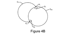
ここで図4A〜図4Cを参照すると、1つの高い信頼度/信頼性(すなわち、既知の高い精度)の範囲/半径が利用可能である場合には、この範囲/半径によって規定される円の外周が、UE101の全ての取り得る場所を識別することができる。例えば、図2〜図4Cの例では、測距源A2は高信頼度の測距源であるので、UE101は、距離dA2にある測距源A2を中心にした円CA2の外周上のどこかに位置すると判断することができる。さらに、図4B及び図5を参照すると、円CA2及びCT3が点P1及びP2において交差するので、UE101は、円CA2の外周上の点P1付近、又は点P2付近に位置すると判断することができる(ブロック509)。
Referring now to FIGS. 4A-4C, if one high confidence / reliability (ie known high accuracy) range / radius is available, the circle defined by this range / radius The perimeter can identify all possible locations for the
言い換えると、他の測距源サイトからの更なる範囲が、高精度の範囲の円CA2の外周と交差することができる。例えば、図4Bの交点P1及びP2はUE101の2つの取り得る近似的な場所を示す。詳細には、低い精度/信頼度の範囲の円CT3の精度/信頼性の結果として、交点P1及びP2に対応する不確定範囲U1及びU2が生じる場合があるので、それらの場所は近似である。不確定範囲U1及びU2は、低い精度/信頼度の範囲の円CT3に関連付けられる最大の不確定性によってだけでなく、円CA2及びCT3のサイズによって規定される場合があり、U1及びU2の大きさは等しい場合がある。不確定範囲U1及びU2はそれぞれ、高精度の範囲の円CA2の外周上の点によって囲まれる場合がある。
In other words, further ranges from other ranging source sites can intersect the outer circumference of the circle CA2 with a high accuracy range. For example, the intersection points P 1 and P 2 in FIG. 4B indicate two possible approximate locations of the
図4A〜図4Cは、図3Bに示される測距源A2及びT3の範囲dA2及びdT3にそれぞれ対応する2つの交差する円CA2及びCT3の簡略化された図を示す。さらに、図5のブロック507において高精度の範囲の円CA2上に射影される範囲は、円CA2と、射影された範囲dT3’との単一の交点を与えることができ、そのような交点は、対応する不確定範囲を有する場合がある。したがって、図3A及び図3C並びに図5のブロック507及び509を参照すると、UE101は、円CA2と、射影された範囲dT3’との交点付近に位置すると判断することができる。
4A-4C show simplified diagrams of two intersecting circles C A2 and C T3 corresponding respectively to ranges d A2 and d T3 of ranging sources A 2 and T 3 shown in FIG. 3B. Further, the range projected on the high accuracy range circle C A2 in
図4C及び図5を参照すると、第3の測距源を用いて、高精度の範囲の円CA2の外周に沿ってUE101の位置場所を更に規定する/絞り込むことができる(ブロック511)。例えば、図4Cを参照すると、第3の範囲が利用可能になった後に、第3の範囲は、(a)2つの点P1及びP2/不確定範囲U1及びU2のうちの一方を除去することができ、及び/又は(b)残りの不確定範囲U1を制限する別の境界基準を与えることができる。詳細には、図4Cは、測距源T5の範囲に対応する円CT5が、点P1において高精度の範囲の円CA2と交差することができ、それゆえ、UE101がその付近に配置される場合がある取り得る場所としての点P2を排除できることを示す。さらに、高精度の範囲の円CA2と交差することによって、円CT5は、残りの不確定範囲U1を制限する別の境界基準を与えることができる。さらに、2つの低い精度/信頼度の円CT3及びCT5の交差を用いて、不確定範囲U1を高精度の範囲の円CA2の外周の、より小さな弧に制限することができる。更なる範囲(すなわち、第4の範囲、第5の範囲、又はそれ以上の範囲)が、不確定範囲U1を分離し、高精度の範囲の円CA2の外周の、より小さな弧に更に制限することができる。
Referring to FIGS. 4C and 5, a third ranging source can be used to further define / narrow the location location of
したがって、1つ又は複数の低い精度/信頼水準の範囲と高い精度/信頼水準の信頼できる基準範囲とを組み合わせることによって、そして場合によっては、幾何学的射影を用いることによって、本発明の概念の種々の実施形態は、通信システムに実質的な処理負荷を加えることなく、位置−場所を求める際の誤差を低減することができる。さらに、高い精度/信頼水準の信頼できる基準範囲及び1つ又は複数の低い精度/信頼水準の範囲はそれぞれ、異なるPLS内の測距源に対応する(及び/又は異なるタイプのPLSに対応する)ことができる。 Thus, by combining one or more low accuracy / confidence level ranges and high accuracy / confidence level reliable reference ranges, and in some cases, using geometric projections, Various embodiments can reduce errors in determining position-location without adding substantial processing load to the communication system. Furthermore, a reliable reference range of high accuracy / confidence level and one or more low accuracy / confidence level ranges each correspond to a ranging source in a different PLS (and / or to a different type of PLS). be able to.
また、図6は、幾つかの実施形態による、ワイヤレス電子ユーザデバイス(すなわちUE)101のブロック図である。図6に示されるように、ワイヤレス電子ユーザデバイス101は、アンテナシステム646と、送受信機642と、プロセッサ(例えば、プロセッサ回路)651と、メモリ653とを含むことができる。さらに、ワイヤレス電子ユーザデバイス101は、オプションで、ディスプレイ654、ユーザインターフェース652、スピーカ656、カメラ658及び/又はマイクロフォン650を含むことができる。
FIG. 6 is a block diagram of a wireless electronic user device (ie, UE) 101 according to some embodiments. As shown in FIG. 6, the wireless
送受信機642の送信機部分は、ワイヤレス電子ユーザデバイス101によって送信されることになる情報を、無線通信に適した電磁信号に変換することができる。送受信機642の受信機部分は、ワイヤレス電子ユーザデバイス101によって(例えば、図1A〜図3Cに示される送信機/測距源のうちの1つから)受信される電磁信号を復調することができる。送受信機642は、個々のRF給電部を介してアンテナシステム646の異なる放射素子にRF信号を供給/受信するための別々の通信パスを与える送信/受信回路(TX/RX)を含むことができる。したがって、アンテナシステム646が2つの能動アンテナ素子を含むとき、送受信機642は、個々のRF給電部を介してアンテナ素子のうちの異なるアンテナ素子に接続される2つの送信/受信回路643、645を含むことができる。
The transmitter portion of the
更に図6を参照すると、メモリ653は、プロセッサ回路651によって実行されるときに、ワイヤレス電子ユーザデバイス101の動作(例えば、図5のフローチャートに示される)を実行するコンピュータプログラム命令を記憶することができる。一例として、メモリ653は、メモリ653から電源が外されている間も記憶されたデータを保持する、フラッシュメモリのような不揮発性メモリとすることができる。
Still referring to FIG. 6, the
本明細書において、上記の説明及び図面に関連して本発明の概念の種々の異なる実施形態が開示されてきた。これらの実施形態の全ての組み合わせ及び部分的組み合わせをそのまま説明し示すことは、過度に繰返しが多くわかりにくいものとなることが理解されよう。したがって、図面を含む本明細書は、本明細書において説明される本発明の概念の実施形態並びにそれらを作成し用いる方式及びプロセスの全ての組み合わせ及び部分的組み合わせの完全な記載を構成すると解釈されるものとし、任意のそのような組み合わせ又は部分的組み合わせに対する特許請求を支持するものとする。 Various different embodiments of the inventive concept have been disclosed herein in connection with the above description and drawings. It will be understood that describing and showing all combinations and subcombinations of these embodiments as is would be overly repetitive and difficult to understand. Accordingly, this specification, including the drawings, is to be construed as constituting a complete description of the embodiments of the inventive concepts described herein, as well as all combinations and subcombinations of methods and processes for making and using them. And to support claims for any such combination or subcombination.
図面及び明細書に、本発明の概念の例示的な実施形態が開示されている。特定の用語が使用されているが、それらの用語は、一般的かつ説明的な意味でのみ用いられ、限定の目的では用いられていない。本発明の概念の範囲は、この後に続く特許請求の範囲に規定されている。 In the drawings and specification, there have been disclosed exemplary embodiments of the inventive concept. Although specific terms are used, they are used in a general and descriptive sense only and not for purposes of limitation. The scope of the inventive concept is defined in the claims that follow.
Claims (26)
前記高信頼度の第1の測距源より低い信頼度に対応する第2の測距源からのシグナリングを用いて、前記ワイヤレスユーザデバイスのための第2の範囲を求めるステップと、
前記第1の範囲及び前記第2の範囲に基づいてそれぞれ画定された第1の幾何学的形状及び第2の幾何学的形状が交差するか否かを判断するステップと、
第3の測距源からのシグナリングを用いて、前記ワイヤレスユーザデバイスのための第3の範囲を求めるステップと、
前記第3の範囲を用いて、前記第1の幾何学的形状の外周に沿った位置を示すことによって、前記ワイヤレスユーザデバイスの位置−場所を求めるステップと、
を含む、位置−場所を求める方法。 Determining a first range for the wireless user device using signaling from a reliable first ranging source;
Determining a second range for the wireless user device using signaling from a second ranging source that corresponds to a lower reliability than the first reliable ranging source;
Determining whether a first geometric shape and a second geometric shape respectively defined based on the first range and the second range intersect;
Determining a third range for the wireless user device using signaling from a third ranging source;
Determining a position-location of the wireless user device by indicating a position along an outer periphery of the first geometry using the third range;
A method for determining a location-location, including:
前記第1の幾何学的形状及び前記第2の幾何学的形状が交差しないと判断することに応答して、前記第2の範囲を、前記高信頼度の第1の測距源の前記第1の範囲に基づいて画定された前記第1の幾何学的形状上に射影するステップを含む、請求項2に記載の方法。 Adjusting the second range comprises:
In response to determining that the first geometric shape and the second geometric shape do not intersect, the second range is defined as the first range of the reliable first ranging source. The method of claim 2, comprising projecting onto the first geometric shape defined based on a range of one.
前記第2の範囲を射影するステップは、前記第2の円の外周が前記第1の円の前記外周上にあるように、前記第2の円の半径を増加又は減少させるステップを含む、請求項3に記載の方法。 The first geometric shape and the second geometric shape each include a first circle and a second circle that do not intersect;
The step of projecting the second range includes increasing or decreasing a radius of the second circle such that an outer circumference of the second circle is on the outer circumference of the first circle. Item 4. The method according to Item 3.
前記第1の範囲は前記第1の円の半径を規定する、請求項4に記載の方法。 The first range indicates a distance between the first ranging source and the wireless user device;
The method of claim 4, wherein the first range defines a radius of the first circle.
前記第1の幾何学的形状及び前記第2の幾何学的形状が交差するか否かを判断するステップの後に、前記第3の範囲を用いて、前記第1の幾何学的形状の前記外周に沿った前記位置を示すことによって、前記ワイヤレスユーザデバイスの前記位置−場所を求めるステップを含む、請求項1〜6のいずれか一項に記載の方法。 Determining the location-location of the wireless user device comprises:
After the step of determining whether the first geometric shape and the second geometric shape intersect, the outer circumference of the first geometric shape using the third range The method according to claim 1, comprising determining the position-location of the wireless user device by indicating the position along a line.
前記同じタイプは、グローバルポジショニングシステム(GPS)、Wi−Fi、セルラ又は地上ビーコンネットワーク(TBN)のうちの1つを含む、請求項9に記載の方法。 The different location systems include the same type of location system;
The method of claim 9, wherein the same type comprises one of a global positioning system (GPS), Wi-Fi, cellular or terrestrial beacon network (TBN).
前記異なるタイプは、グローバルポジショニングシステム(GPS)、Wi−Fi、セルラ及び地上ビーコンネットワーク(TBN)のうちの異なるものを含む、請求項9に記載の方法。 The different location systems include different types of location systems;
10. The method of claim 9, wherein the different types include different ones of global positioning system (GPS), Wi-Fi, cellular and terrestrial beacon network (TBN).
前記第1の範囲計算値は前記第2の範囲計算値より正確である、請求項1〜12のいずれか一項に記載の方法。 The first range and the second range include a first range calculation value and a second range calculation value, respectively.
The method according to claim 1, wherein the first range calculation value is more accurate than the second range calculation value.
受信信号パラメータ、
位置特定システムタイプ、
測距源高度、
前記ワイヤレスユーザデバイスへの測距源近接度、
最も制限された範囲の測距源、
最も高い精度の範囲計算値を与える履歴、及び
測距源帯域幅、
のうちの少なくとも1つに基づいて、前記ワイヤレスユーザデバイスの前記位置−場所を求めるステップにおいて使用するための前記高信頼度の第1の測距源を選択するステップを含む、請求項1〜13のいずれか一項に記載の方法。 The step of obtaining the first range includes:
Receive signal parameters,
Location system type,
Ranging source altitude,
Ranging source proximity to the wireless user device;
The most limited range source,
History giving the most accurate range calculation, and source bandwidth,
Selecting the reliable first ranging source for use in determining the position-location of the wireless user device based on at least one of the following: The method as described in any one of.
受信信号強度測距源、
信号対雑音比測距源、及び
相関ピークの形状、
のうちの少なくとも1つを含む、請求項14に記載の方法。 The received signal parameter is:
Received signal strength ranging source,
A signal-to-noise ratio ranging source, and the shape of the correlation peak,
15. The method of claim 14, comprising at least one of:
前記高信頼度の第1の測距源が、複数の測距源の中の最も高い信頼度及び/又は最も高い精度の測距源を含むと判断するステップと、
前記高信頼度の第1の測距源が、前記複数の測距源の中の前記最も高い信頼度及び/又は最も高い精度の測距源を含むと判断することに応答して、前記ワイヤレスユーザデバイスの前記位置−場所を求めるステップにおいて使用するための前記高信頼度の第1の測距源を選択するステップと、
を含む、請求項1〜15のいずれか一項に記載の方法。 The step of obtaining the first range includes:
Determining that the first reliable ranging source includes a highest reliability and / or highest accuracy ranging source among a plurality of ranging sources;
In response to determining that the first reliable ranging source includes the highest reliability and / or highest accuracy ranging source among the plurality of ranging sources. Selecting the reliable first ranging source for use in determining the position-location of a user device;
The method according to claim 1, comprising:
前記高信頼度の第1の測距源が信号品質のしきい値レベルを超えると判断するステップと、
前記高信頼度の第1の測距源が信号品質の前記しきい値レベルを超えると判断することに応答して、前記ワイヤレスユーザデバイスの前記位置−場所を求めるステップにおいて使用するための前記高信頼度の第1の測距源を選択するステップと、
を含む、請求項1〜16のいずれか一項に記載の方法。 The step of obtaining the first range includes:
Determining that the first reliable ranging source exceeds a threshold level of signal quality;
In response to determining that the first reliable ranging source exceeds the threshold level of signal quality, the high for use in determining the location-location of the wireless user device Selecting a first ranging source of reliability;
The method according to claim 1, comprising:
前記ワイヤレスユーザデバイスを用いて、前記高信頼度の第1の測距源より低い信頼度に対応する第2の測距源からのシグナリングを用いて、前記ワイヤレスユーザデバイスのための第2の範囲計算値を求めるステップであって、前記第1の範囲計算値及び前記第2の範囲計算値はそれぞれ第1の円及び第2の円の第1の半径及び第2の半径を規定する、求めるステップと、
前記ワイヤレスユーザデバイスを用いて、前記第2の半径の端点が前記第1の円の外周上にあるように前記第2の半径を増加又は減少させることによって、前記第2の範囲計算値を前記第1の円上に射影するステップと、
前記第1の円の前記外周上の前記第2の半径の前記端点を用いることによって、前記ワイヤレスユーザデバイスの位置−場所を求めるステップと、
を含む、位置−場所を求める方法。 Using a wireless user device to determine a reliable first range calculation for the wireless user device using signaling from a reliable first ranging source;
Using the wireless user device, a second range for the wireless user device using signaling from a second ranging source that corresponds to a lower reliability than the first reliable ranging source. Obtaining a calculated value, wherein the first range calculated value and the second range calculated value define a first radius and a second radius of the first circle and the second circle, respectively; Steps,
Using the wireless user device, increasing or decreasing the second radius so that the end point of the second radius is on the outer circumference of the first circle, thereby calculating the second range calculation value Projecting onto a first circle;
Determining the position-location of the wireless user device by using the end point of the second radius on the outer circumference of the first circle;
A method for determining a location-location, including:
前記第2の範囲計算値を射影するステップは、前記第1の範囲計算値及び前記第2の範囲計算値にそれぞれ対応する前記第1の円及び前記第2の円が交差しないと判断することに応答して、前記第2の半径の前記端点が前記第1の円の前記外周上にあるように前記第2の半径を増加又は減少させることによって、前記第2の範囲計算値を前記第1の円上に射影するステップを含む、請求項20に記載の方法。 Determining whether or not the first circle and the second circle corresponding to the first range calculation value and the second range calculation value respectively intersect with the wireless user device; Including
The step of projecting the second range calculation value determines that the first circle and the second circle respectively corresponding to the first range calculation value and the second range calculation value do not intersect with each other. In response to the second range calculation value by increasing or decreasing the second radius such that the end point of the second radius is on the outer circumference of the first circle. 21. The method of claim 20, comprising projecting onto a circle of one.
前記ワイヤレスユーザデバイスの前記位置−場所を求めるステップは、
前記第3の範囲計算値を使用して、前記第1の円の前記外周に沿った位置を示すステップを更に含む、請求項20又は21に記載の方法。 Using the wireless user device to determine a third range calculation for the wireless user device using signaling from a third ranging source;
Determining the location-location of the wireless user device comprises:
22. A method according to claim 20 or 21, further comprising the step of using the third range calculation to indicate a position along the circumference of the first circle.
高信頼度の第1の測距源からのシグナリングを用いて、該ワイヤレスユーザデバイスのための高信頼度の第1の範囲計算値を求めることと、
前記高信頼度の第1の測距源より低い信頼度に対応する第2の測距源からのシグナリングを用いて、該ワイヤレスユーザデバイスのための第2の範囲計算値を求めることであって、前記第1の範囲計算値及び前記第2の範囲計算値はそれぞれ第1の円及び第2の円の第1の半径及び第2の半径を規定する、求めることと、
前記第2の半径の端点が前記第1の円の外周上にあるように前記第2の半径を増加又は減少させることによって、前記第2の範囲計算値を前記第1の円上に射影することと、
前記第1の円の前記外周上の前記第2の半径の前記端点を用いることによって、該ワイヤレスユーザデバイスの位置−場所を求めることと、
を行うように構成されるプロセッサを備える、ワイヤレスユーザデバイス。 A wireless user device,
Determining a first reliable range calculation for the wireless user device using signaling from a first reliable ranging source;
Determining a second range calculation for the wireless user device using signaling from a second ranging source corresponding to a lower reliability than the first reliable ranging source; The first range calculation value and the second range calculation value define a first radius and a second radius of the first circle and the second circle, respectively, and
Projecting the second range calculation value onto the first circle by increasing or decreasing the second radius so that the end point of the second radius is on the outer circumference of the first circle. And
Determining the location-location of the wireless user device by using the end points of the second radius on the outer circumference of the first circle;
A wireless user device comprising a processor configured to:
前記第1の範囲計算値及び前記第2の範囲計算値にそれぞれ対応する前記第1の円及び前記第2の円が交差するか否かを判断することと、
前記第1の範囲計算値及び前記第2の範囲計算値にそれぞれ対応する前記第1の円及び前記第2の円が交差しないと判断することに応答して、前記第2の半径の前記端点が前記第1の円の前記外周上にあるように前記第2の半径を増加又は減少させることによって、前記第2の範囲計算値を前記第1の円上に射影することと、
を行うように更に構成される、請求項24に記載のワイヤレスユーザデバイス。 The processor is
Determining whether the first circle and the second circle corresponding to the first range calculation value and the second range calculation value respectively intersect;
In response to determining that the first circle and the second circle corresponding to the first range calculation value and the second range calculation value respectively do not intersect, the end point of the second radius Projecting the second range calculation onto the first circle by increasing or decreasing the second radius so that is on the outer circumference of the first circle;
25. The wireless user device of claim 24, further configured to:
第3の測距源からのシグナリングを用いて、前記ワイヤレスユーザデバイスのための第3の範囲計算値を求めることと、
前記第3の範囲計算値を用いて前記第1の円の前記外周に沿った位置を示すことによって、前記ワイヤレスユーザデバイスの前記位置−場所を求めることと、
を行うように更に構成される、請求項24又は25に記載のワイヤレスユーザデバイス。 The processor is
Determining a third range calculation for the wireless user device using signaling from a third ranging source;
Determining the position-location of the wireless user device by indicating a position along the circumference of the first circle using the third range calculation value;
26. A wireless user device according to claim 24 or 25, further configured to:
Applications Claiming Priority (3)
| Application Number | Priority Date | Filing Date | Title |
|---|---|---|---|
| US201361821871P | 2013-05-10 | 2013-05-10 | |
| US61/821,871 | 2013-05-10 | ||
| PCT/US2014/037270 WO2014182883A1 (en) | 2013-05-10 | 2014-05-08 | Methods of position-location determination using a high-confidence range, and related systems and devices |
Publications (1)
| Publication Number | Publication Date |
|---|---|
| JP2016524699A true JP2016524699A (en) | 2016-08-18 |
Family
ID=51864394
Family Applications (1)
| Application Number | Title | Priority Date | Filing Date |
|---|---|---|---|
| JP2016513061A Withdrawn JP2016524699A (en) | 2013-05-10 | 2014-05-08 | Method for determining position-location using a high reliability range and related systems and devices |
Country Status (4)
| Country | Link |
|---|---|
| US (1) | US20140333482A1 (en) |
| EP (1) | EP2979483A4 (en) |
| JP (1) | JP2016524699A (en) |
| WO (1) | WO2014182883A1 (en) |
Families Citing this family (3)
| Publication number | Priority date | Publication date | Assignee | Title |
|---|---|---|---|---|
| US10237349B1 (en) | 2015-05-11 | 2019-03-19 | Providence IP, LLC | Method and system for the organization and maintenance of social media information |
| FR3085490B1 (en) * | 2018-08-30 | 2020-08-14 | Second Bridge Inc | GEOLOCATION PROCESSES USING AN ELECTRONIC DISTANCE MEASURING EQUIPMENT |
| US12366650B2 (en) * | 2020-12-31 | 2025-07-22 | Hitachi Rail Gts Canada Inc. | Method and system for high-integrity vehicle localization |
Family Cites Families (20)
| Publication number | Priority date | Publication date | Assignee | Title |
|---|---|---|---|---|
| US6021330A (en) * | 1997-07-22 | 2000-02-01 | Lucent Technologies Inc. | Mobile location estimation in a wireless system using designated time intervals of suspended communication |
| US6313786B1 (en) * | 1998-07-02 | 2001-11-06 | Snaptrack, Inc. | Method and apparatus for measurement processing of satellite positioning system (SPS) signals |
| US6321092B1 (en) * | 1998-11-03 | 2001-11-20 | Signal Soft Corporation | Multiple input data management for wireless location-based applications |
| US6430504B1 (en) * | 2000-03-07 | 2002-08-06 | Trimble Navigation Ltd. | User interface for global positioning system receiver |
| EP1174728B1 (en) * | 2000-07-18 | 2008-09-24 | Hewlett-Packard Company | Location data diffusion and location discovery |
| US7254401B2 (en) * | 2000-12-19 | 2007-08-07 | Nokia Corporation | Network-based method and system for determining a location of user equipment in CDMA networks |
| US20030125045A1 (en) * | 2001-12-27 | 2003-07-03 | Riley Wyatt Thomas | Creating and using base station almanac information in a wireless communication system having a position location capability |
| US7623871B2 (en) * | 2002-04-24 | 2009-11-24 | Qualcomm Incorporated | Position determination for a wireless terminal in a hybrid position determination system |
| US7379757B2 (en) * | 2002-10-16 | 2008-05-27 | Andrew Corporation | System and method for estimating the multi-path delays in a signal using a spatially blind antenna array |
| US7319397B2 (en) * | 2004-08-26 | 2008-01-15 | Avante International Technology, Inc. | RFID device for object monitoring, locating, and tracking |
| WO2008017034A2 (en) * | 2006-08-03 | 2008-02-07 | Ntt Docomo Inc. | Weighted least square localization method exploiting multipath channel statistics for non-line-of-sight mitigation |
| US7683835B2 (en) * | 2006-08-15 | 2010-03-23 | Computer Associates Think, Inc. | System and method for locating wireless devices |
| US7528776B2 (en) * | 2007-03-22 | 2009-05-05 | Nortel Networks Limited | Beacon-assisted precision location of untethered client in packet networks |
| WO2010005731A1 (en) * | 2008-06-16 | 2010-01-14 | Skyhook Wireless, Inc. | Methods and systems for determining location using a cellular and wlan positioning system by selecting the best wlan ps solution |
| US8200239B2 (en) * | 2008-11-11 | 2012-06-12 | Trueposition, Inc. | Femto-cell location by proxy methods |
| US8180368B2 (en) * | 2008-11-11 | 2012-05-15 | Trueposition, Inc. | Femto-cell location by direct methods |
| US8165150B2 (en) * | 2008-12-17 | 2012-04-24 | Avaya Inc. | Method and system for wireless LAN-based indoor position location |
| US20110109506A1 (en) * | 2009-09-24 | 2011-05-12 | Coherent Navigation, Inc. | Simulating Phase-Coherent GNSS Signals |
| KR101424747B1 (en) * | 2010-11-15 | 2014-08-01 | 한국전자통신연구원 | Method and apparatus for position estimation of access point in wi-fi system |
| US9330468B2 (en) * | 2012-02-29 | 2016-05-03 | RetailNext, Inc. | Method and system for analyzing interactions |
-
2014
- 2014-05-08 JP JP2016513061A patent/JP2016524699A/en not_active Withdrawn
- 2014-05-08 WO PCT/US2014/037270 patent/WO2014182883A1/en not_active Ceased
- 2014-05-08 EP EP14795326.9A patent/EP2979483A4/en not_active Withdrawn
- 2014-05-08 US US14/273,004 patent/US20140333482A1/en not_active Abandoned
Also Published As
| Publication number | Publication date |
|---|---|
| WO2014182883A1 (en) | 2014-11-13 |
| US20140333482A1 (en) | 2014-11-13 |
| EP2979483A4 (en) | 2017-01-18 |
| EP2979483A1 (en) | 2016-02-03 |
Similar Documents
| Publication | Publication Date | Title |
|---|---|---|
| KR101842565B1 (en) | Access point location discovery in unmanaged networks | |
| US10809350B2 (en) | Hybrid fingerprinting/OTDOA positioning techniques and systems | |
| JP4100320B2 (en) | Position detection system and apparatus | |
| CN102958154B (en) | Method and device for positioning user equipment | |
| US10175364B2 (en) | Systems and methods for estimating whether a receiver is inside or outside a building | |
| JP7108626B2 (en) | Method and system for locating a terminal in a wireless communication system | |
| US20170150436A1 (en) | Apparatuses and Methods therein for Positioning Measurements | |
| CN102036165A (en) | Positioning method and user terminal supporting multiple positioning modes | |
| JPWO2005012939A1 (en) | Terminal positioning method and system | |
| KR20140108544A (en) | Methods and apparatuses for use in selecting a transmitting device for use in a positioning function | |
| KR20170074563A (en) | Access point and method for estimating location of terminal by using aoa positioning technique | |
| US10219103B2 (en) | Power-efficient location estimation | |
| CN105164546A (en) | Methods and apparatuses for characterizing and affecting mobile device location accuracy and/or uncertainty | |
| US20210044670A1 (en) | Selecting a positioning technique based on the accuracy | |
| US9210543B2 (en) | Apparatus for determining indoor location and method for determining indoor location in multi-story building using the same | |
| JP2016200466A (en) | Electronic equipment, position specification program, and position specification method | |
| US20160124069A1 (en) | Systems and methods for estimating a two-dimensional position of a receiver | |
| US9942815B1 (en) | Method and apparatus for location determination of a base station at a client device | |
| KR20190128371A (en) | Apparatus and method for measuring location, and apparatus and method for constructing database for measuring location | |
| JP2016524699A (en) | Method for determining position-location using a high reliability range and related systems and devices | |
| KR101234498B1 (en) | Position estimating system and method of portable terminal | |
| US20230041613A1 (en) | Method of prior channel information transmission | |
| US20130196683A1 (en) | Method for positioning and apparatus for performing the same | |
| WO2020104071A1 (en) | Position determination | |
| KR101202194B1 (en) | Position estimating system and method of portable terminal |
Legal Events
| Date | Code | Title | Description |
|---|---|---|---|
| A521 | Request for written amendment filed |
Free format text: JAPANESE INTERMEDIATE CODE: A523 Effective date: 20160113 |
|
| A621 | Written request for application examination |
Free format text: JAPANESE INTERMEDIATE CODE: A621 Effective date: 20160706 |
|
| A761 | Written withdrawal of application |
Free format text: JAPANESE INTERMEDIATE CODE: A761 Effective date: 20170405 |
|
| A521 | Request for written amendment filed |
Free format text: JAPANESE INTERMEDIATE CODE: A821 Effective date: 20170405 |