JP2016516520A - Patient interface device - Google Patents
Patient interface device Download PDFInfo
- Publication number
- JP2016516520A JP2016516520A JP2016509567A JP2016509567A JP2016516520A JP 2016516520 A JP2016516520 A JP 2016516520A JP 2016509567 A JP2016509567 A JP 2016509567A JP 2016509567 A JP2016509567 A JP 2016509567A JP 2016516520 A JP2016516520 A JP 2016516520A
- Authority
- JP
- Japan
- Prior art keywords
- strap
- interface device
- patient interface
- patient
- frame
- Prior art date
- Legal status (The legal status is an assumption and is not a legal conclusion. Google has not performed a legal analysis and makes no representation as to the accuracy of the status listed.)
- Granted
Links
Images





Classifications
-
- A—HUMAN NECESSITIES
- A61—MEDICAL OR VETERINARY SCIENCE; HYGIENE
- A61M—DEVICES FOR INTRODUCING MEDIA INTO, OR ONTO, THE BODY; DEVICES FOR TRANSDUCING BODY MEDIA OR FOR TAKING MEDIA FROM THE BODY; DEVICES FOR PRODUCING OR ENDING SLEEP OR STUPOR
- A61M16/00—Devices for influencing the respiratory system of patients by gas treatment, e.g. ventilators; Tracheal tubes
- A61M16/06—Respiratory or anaesthetic masks
- A61M16/0605—Means for improving the adaptation of the mask to the patient
-
- A—HUMAN NECESSITIES
- A61—MEDICAL OR VETERINARY SCIENCE; HYGIENE
- A61M—DEVICES FOR INTRODUCING MEDIA INTO, OR ONTO, THE BODY; DEVICES FOR TRANSDUCING BODY MEDIA OR FOR TAKING MEDIA FROM THE BODY; DEVICES FOR PRODUCING OR ENDING SLEEP OR STUPOR
- A61M16/00—Devices for influencing the respiratory system of patients by gas treatment, e.g. ventilators; Tracheal tubes
- A61M16/06—Respiratory or anaesthetic masks
- A61M16/0666—Nasal cannulas or tubing
-
- A—HUMAN NECESSITIES
- A61—MEDICAL OR VETERINARY SCIENCE; HYGIENE
- A61M—DEVICES FOR INTRODUCING MEDIA INTO, OR ONTO, THE BODY; DEVICES FOR TRANSDUCING BODY MEDIA OR FOR TAKING MEDIA FROM THE BODY; DEVICES FOR PRODUCING OR ENDING SLEEP OR STUPOR
- A61M16/00—Devices for influencing the respiratory system of patients by gas treatment, e.g. ventilators; Tracheal tubes
- A61M16/06—Respiratory or anaesthetic masks
-
- A—HUMAN NECESSITIES
- A61—MEDICAL OR VETERINARY SCIENCE; HYGIENE
- A61M—DEVICES FOR INTRODUCING MEDIA INTO, OR ONTO, THE BODY; DEVICES FOR TRANSDUCING BODY MEDIA OR FOR TAKING MEDIA FROM THE BODY; DEVICES FOR PRODUCING OR ENDING SLEEP OR STUPOR
- A61M16/00—Devices for influencing the respiratory system of patients by gas treatment, e.g. ventilators; Tracheal tubes
- A61M16/06—Respiratory or anaesthetic masks
- A61M16/0683—Holding devices therefor
-
- A—HUMAN NECESSITIES
- A61—MEDICAL OR VETERINARY SCIENCE; HYGIENE
- A61M—DEVICES FOR INTRODUCING MEDIA INTO, OR ONTO, THE BODY; DEVICES FOR TRANSDUCING BODY MEDIA OR FOR TAKING MEDIA FROM THE BODY; DEVICES FOR PRODUCING OR ENDING SLEEP OR STUPOR
- A61M16/00—Devices for influencing the respiratory system of patients by gas treatment, e.g. ventilators; Tracheal tubes
- A61M16/08—Bellows; Connecting tubes ; Water traps; Patient circuits
- A61M16/0816—Joints or connectors
-
- A—HUMAN NECESSITIES
- A61—MEDICAL OR VETERINARY SCIENCE; HYGIENE
- A61M—DEVICES FOR INTRODUCING MEDIA INTO, OR ONTO, THE BODY; DEVICES FOR TRANSDUCING BODY MEDIA OR FOR TAKING MEDIA FROM THE BODY; DEVICES FOR PRODUCING OR ENDING SLEEP OR STUPOR
- A61M2205/00—General characteristics of the apparatus
- A61M2205/02—General characteristics of the apparatus characterised by a particular materials
-
- A—HUMAN NECESSITIES
- A61—MEDICAL OR VETERINARY SCIENCE; HYGIENE
- A61M—DEVICES FOR INTRODUCING MEDIA INTO, OR ONTO, THE BODY; DEVICES FOR TRANSDUCING BODY MEDIA OR FOR TAKING MEDIA FROM THE BODY; DEVICES FOR PRODUCING OR ENDING SLEEP OR STUPOR
- A61M2205/00—General characteristics of the apparatus
- A61M2205/60—General characteristics of the apparatus with identification means
- A61M2205/6045—General characteristics of the apparatus with identification means having complementary physical shapes for indexing or registration purposes
Landscapes
- Health & Medical Sciences (AREA)
- Pulmonology (AREA)
- Life Sciences & Earth Sciences (AREA)
- Animal Behavior & Ethology (AREA)
- Anesthesiology (AREA)
- Biomedical Technology (AREA)
- Heart & Thoracic Surgery (AREA)
- Hematology (AREA)
- Emergency Medicine (AREA)
- Engineering & Computer Science (AREA)
- General Health & Medical Sciences (AREA)
- Public Health (AREA)
- Veterinary Medicine (AREA)
- Otolaryngology (AREA)
- Orthopedics, Nursing, And Contraception (AREA)
- Magnetic Resonance Imaging Apparatus (AREA)
Abstract
ガスのフローを受けるように構成されたクッションと、クッションと結合されるフレームと、フレームの中央から延在しているストラップとを含む、患者インタフェース装置が提供される。ヘッドギアコンポーネントは、使用時に、患者の頭の上とフィットするように適合された上部と、患者の頭の後ろとフィットするように適合されたリア部と、ストラップをヘッドギアコンポーネントに結合する結合機構と、を含む。結合機構は、開口を含み、ストラップの端部は、結合機構における開口を通るように構成される。ストラップの端部は、フレームの中央部に向かう方向において折り畳まれ、ストラップの端部をフレームの中央部に向かって引くことが患者インタフェース装置を締める動作となるように、ストラップに解放可能なように取り付けられる。A patient interface device is provided that includes a cushion configured to receive a flow of gas, a frame coupled to the cushion, and a strap extending from a center of the frame. The headgear component includes, in use, an upper portion adapted to fit over the patient's head, a rear portion adapted to fit behind the patient's head, and a coupling mechanism that couples the strap to the headgear component. ,including. The coupling mechanism includes an opening and the end of the strap is configured to pass through the opening in the coupling mechanism. The end of the strap is folded in the direction toward the center of the frame so that pulling the end of the strap toward the center of the frame can be releasable to the strap so that the patient interface device is tightened It is attached.
Description
(関連出願への相互参照)
本願は、U.S.C.119条(e)の下で、2013年4月23日に出願された米国仮出願第61/814,853号の優先権の利益を主張する。当該仮出願の内容は、参照により本明細書に取り込まれる。
(Cross-reference to related applications)
This application claims the benefit of priority of US Provisional Application No. 61 / 814,853 filed Apr. 23, 2013 under USC 119 (e). The contents of the provisional application are incorporated herein by reference.
本発明は、概して、患者の気道に気体フローを供給する圧力サポートシステムにおいて用いられる患者インタフェース装置に関し、より具体的には、かかる患者インタフェース装置の選択された部分に関する。 The present invention relates generally to patient interface devices used in pressure support systems that provide gas flow to a patient's airway, and more particularly to selected portions of such patient interface devices.
閉塞性睡眠時無呼吸(OSA:Obstructive Sleep Apnea)は、世界中の数百万人の人々に影響を与えている。OSAは、す意味中の呼吸における妨害又は停止によって特徴付けられる。OSAの発現は、少なくとも10秒間続き、しばしば1〜2分にも及ぶ、睡眠中のエアフローの部分的又は完全な妨害に起因する。所与の夜において、中程度から深刻な無呼吸を患っている人々は、一晩につき200〜500回の完全又は部分的な呼吸中断を経験し得る。彼らの睡眠は常に中断されるため、彼らは、心身の効率的機能のために必要な回復睡眠を奪われている。この睡眠障害は、高血圧、うつ病、脳卒中、心不整脈、心筋梗塞、及び、他の心疾患と紐付けられている。また、OSAは、極度の披露を生じさせる。 Obstructive sleep apnea (OSA) affects millions of people around the world. OSA is characterized by obstruction or cessation in breathing. OSA expression is due to partial or complete obstruction of airflow during sleep, which lasts at least 10 seconds and often extends for 1-2 minutes. On a given night, people suffering from moderate to severe apnea may experience 200 to 500 complete or partial respiratory interruptions per night. Because their sleep is always interrupted, they are deprived of the resting sleep necessary for efficient physical and mental function. This sleep disorder has been linked to hypertension, depression, stroke, cardiac arrhythmia, myocardial infarction, and other heart diseases. OSA also causes extreme performance.
OSAを治療するための1つの方法は、陽性気道圧(PAP:Positive Airway Pressure)療法である。知られているPAP療法は、患者の気道を開けるのを補助するために、一定の陽性気道圧が患者の気道に供給される持続的陽性気道圧(CPAP:Continuous PAP)と、患者の気道に供給される圧力が患者の呼吸サイクルとともに変化される可変的気道圧とを含む。上記療法は、一般的に、患者が睡眠中、夜に患者に対して供給される。 One method for treating OSA is positive airway pressure (PAP) therapy. Known PAP therapy involves continuous positive airway pressure (CPAP), in which a constant positive airway pressure is supplied to the patient's airway to help open the patient's airway, and the patient's airway. Including variable airway pressure that is supplied with the patient's respiratory cycle. The therapy is generally delivered to the patient at night while the patient is sleeping.
前述の非侵襲性のベンチレーション及び圧力サポート療法は、呼吸ガスのフローが、患者の気道に対して、圧力/フロー生成装置から運ばれることができるように、ベンチレータ又は圧力サポートシステムを患者の気道とインタフェースするため、一般的に、鼻マスク又は鼻/口マスクである、患者インタフェース装置の患者の顔上における配置を含む。 The non-invasive ventilation and pressure support therapies described above allow the ventilator or pressure support system to be evacuated to the patient's airway so that the flow of breathing gas can be carried from the pressure / flow generator to the patient's airway. Including the placement of a patient interface device on the patient's face, typically a nasal mask or nasal / mouth mask.
患者インタフェース装置は、一般的に、長期間着用されるため、様々な懸念事項が考慮されなければならない。例えば、OSAを治療するためにCPAPを供給する場合、患者は、通常、睡眠している一晩中、患者インタフェース装置を着用する。かかる状況における1つの懸念は、患者インタフェース装置が、可能な限り快適かどうかということであり、そうでない場合、患者は、インタフェース装置の着用を避け、処方された圧力サポート療法の目的を駄目にする可能性がある。他の懸念は、適切にフィットしていない患者インタフェース装置が、患者インタフェース装置と患者との間に隙間を含むことがあるということであり、これは、不要な漏れを生じさせる。このため、患者に適切にフィットする患者インタフェース装置を選択することが望ましい。 Because patient interface devices are typically worn for extended periods of time, various concerns must be considered. For example, when providing CPAP to treat OSA, patients typically wear patient interface devices while sleeping overnight. One concern in such situations is whether the patient interface device is as comfortable as possible, otherwise the patient avoids wearing the interface device and ruins the purpose of the prescribed pressure support therapy. there is a possibility. Another concern is that a patient interface device that is not properly fitted may contain a gap between the patient interface device and the patient, which causes unnecessary leakage. For this reason, it is desirable to select a patient interface device that fits the patient appropriately.
あるタイプの患者インタフェース装置は、鼻枕マスクである。一般的に、鼻枕マスクは、鼻孔の開口を密封するために患者の鼻孔内に受けられるシリコーン鼻カニューレ(業界では鼻枕とも呼ばれる)を持つシリコーン密封クッションを用いる。しかしながら、現在の鼻枕マスクは、患者の鼻孔周囲を満足に密封しつつ、患者のために最適な快適さを供給できていない。 One type of patient interface device is a nasal pillow mask. In general, nasal pillow masks use a silicone sealing cushion with a silicone nasal cannula (also referred to in the industry as a nasal pillow) received within the patient's nostril to seal the opening of the nostril. However, current nasal pillow masks fail to provide optimal comfort for the patient while satisfactorily sealing around the patient's nostril.
従って、本発明の目的は、従来の患者インタフェース装置の欠点を克服する患者インタフェース装置を提供することである。この目的は、患者インタフェース装置の締め付けを調整するために、下方向に引っ張られるように構成されたストラップを供給する、本発明の一実施形態によって達成される。また、この目的は、患者インタフェース装置が、剛体材料又は半剛体材料で作られた挿入部と、柔軟な材料で作られたフレームと、を含む、本発明の他の実施形態によって達成される。 Accordingly, it is an object of the present invention to provide a patient interface device that overcomes the shortcomings of conventional patient interface devices. This object is achieved by an embodiment of the present invention that provides a strap configured to be pulled downward to adjust the tightening of the patient interface device. This object is also achieved by other embodiments of the present invention wherein the patient interface device includes an insert made of a rigid or semi-rigid material and a frame made of a flexible material.
一実施形態において、患者インタフェース装置は、治療用ガスのフローを受けるクッションと、クッションと結合する中央部及び中央部から延在するストラップを持つフレームと、患者の頭の上にフィットする少なくとも1つの上部及び患者の頭の後ろにフィットするリア部を含むヘッドギアコンポーネントと、ストラップをヘッドギアコンポーネントに結合する結合機構であって、開口を持つ結合機構と、を有し、ストラップの端部が、結合機構の開口を通過し、フレームの中央部に向かう方向において折り畳まれ、ストラップに解放可能なように取り付けられ、フレームの中央部へ向かってストラップの端部を引くことが、患者インタフェース装置を締める動作となり、患者インタフェース装置は、患者インタフェース装置とともに使用されるのに適合したクッション部材のための鼻カニューレを含み、当該鼻カニューレは、患者の鼻孔と密封を形成するように好適に変形する。 In one embodiment, the patient interface device comprises a cushion for receiving a flow of therapeutic gas, a frame having a central portion coupled to the cushion and a strap extending from the central portion, and at least one fitting over the patient's head. A headgear component that includes an upper portion and a rear portion that fits behind the patient's head; and a coupling mechanism that couples the strap to the headgear component, the coupling mechanism having an opening, the end of the strap having a coupling mechanism The patient interface device is tightened by pulling the end of the strap toward the center of the frame and releasably attached to the strap. Patient interface device used with patient interface device Includes a nasal cannula for the cushion member which is adapted to be, the nasal cannula is suitably deformed so as to form a seal with the patient's nostrils.
他の実施形態において、患者インタフェース装置は、治療用ガスのフローを受けるように構成されたクッションと、開口を持つフレームと、開口内に配置された挿入部と、を含み、フレームが、柔軟な材料で作られ、挿入部が、剛体材料又は半剛体材料で作られる。 In another embodiment, a patient interface device includes a cushion configured to receive a flow of therapeutic gas, a frame having an opening, and an insert disposed within the opening, wherein the frame is flexible Made of material, the insert is made of rigid or semi-rigid material.
本稿での用法では、単数形は、文脈がそうでないことを明確に指示するのでない限り、複数の言及を含む。本稿での用法では、二つ以上の部分または構成要素が「結合される」という陳述は、それらの部分が直接的または間接的に、すなわち一つもしくは複数の中間部分もしくは構成要素を通じて、結び合わされるまたは協働することを意味する。リンクが生じさえすればよい。本稿での用法では、「直接結合される」は二つの要素が直接互いと接触することを意味する。本稿での用法では、「固定的に結合される」または「固定される」は二つの構成要素が、互いに対する相対的な配向を一定に維持しつつ、一体として動くよう結合されることを意味する。 As used herein, the singular forms include the plural reference unless the context clearly dictates otherwise. As used herein, a statement that two or more parts or components are “combined” means that the parts are combined directly or indirectly, ie, through one or more intermediate parts or components. Or collaborate. All you need to do is create a link. As used in this article, “directly coupled” means that two elements are in direct contact with each other. As used herein, “fixedly coupled” or “fixed” means that two components are coupled to move as a unit while maintaining a constant orientation relative to each other. To do.
本稿で使われる方向に関する句、たとえば限定するものではないが、上、下、左、右、上部、下部、前、後およびそれらの派生語は、図面に示される要素の配向に関係するのであって、請求項において明示的に記載されているのでない限り、請求項を限定するものではない。 Directional phrases used in this article, such as, but not limited to, top, bottom, left, right, top, bottom, front, back, and their derivatives are related to the orientation of the elements shown in the drawing. The claims are not to be restricted unless explicitly stated in the claims.
本発明の一実施例に従った患者に対して呼吸療法のレジメンを供給するのに適したシステム2が、図1において、大まかに示されている。システム2は、圧力生成装置4と、配管6と、屈曲導管10を有する患者インタフェース装置8と、を含む。圧力生成装置4は、呼吸ガスのフローを生成するように構成され、これらに限定されないが、ベンチレータ、一定圧力サポート装置(持続的陽性気道圧装置又はCPAP装置など)、可変的圧力装置(ペンシルバニア州のマリーズヴィルのフィリップスレスピロニクス(登録商標)によって製造販売されるBiPAP(登録商標)、Bi-Flex(登録商標)、又は、C-Flex(登録商標)装置など)、及び、自動滴定圧力サポート装置を含んでいてもよい。配管6は、患者インタフェース装置8に対して、圧力生成装置4からの呼吸ガスのフローを伝達するように構成されている。配管6及び患者インタフェース装置8は、一般的に、患者回路と総称される。
A
(ここで詳述される)本実施形態では、患者インタフェース装置8は、患者の鼻を通じて患者の気道に呼吸ガスを運ぶために、患者の鼻孔内に受けられる鼻カニューレを持つ枕状の鼻クッションを有する。図1に示される例示的な実施形態では、患者インタフェース装置8は、クッション部材12と、開口20を具備する中央部17及び中央部17から延在しているストラップ18(18a,18b)を持つフレーム部材14と、を含む。挿入部16は、中央部17の開口内に配置されている。図1から分かるように、クッション部材12は、本体部24と、本体部24に結合された2つの鼻カニューレ26a,26bと、を含む。
In this embodiment (detailed herein), the
屈曲導管10は、挿入部16と結合するように構成された取り付け部11と、圧力生成装置4からの呼吸ガスのフローが、屈曲導管10を通じて、クッション部材12によって規定される内部空間、ひいては患者の気道に伝達されることを可能とするクッション部材12と、を含む。また、クッション部材12は、(患者の気道からの)呼気ガスのフローが屈曲導管10において供給される排気口22に伝達されることを可能にする。図2に見られるように、取り付け部11は、挿入部16によって形成される開口20内に挿入されるように構成される。取り付け部11及び挿入部16によって形成される開口20は、図1〜図4に示される一般的な三角形状などの然るべき独特な形状を持っていてもよい。然るべき三角形状に関し、挿入部16及び取り付け部11は、互いに正確に配向された場合にのみ結合され、このことは、患者が、患者インタフェース装置8を適切に組み立てることを容易にする。
The
ヘッドギアコンポーネント28は、図1〜図4に示されるように、患者の頭に患者インタフェース装置8を固定するために、結合機構34(34a,34b)を介して、ストラップ18に取り付けられる。ヘッドギアコンポーネント28は、患者の頭の上にフィットするように構成された上部30と、患者の頭の後ろにフィットするリア部32と、を含む。図1〜図4の実施例では、ヘッドギアコンポーネント28の上部30は、調整可能である。しかしながら、開示の外言の範囲から逸脱しない範囲で、上部30、リア部32、上部30及びリア部32の両方が、調整可能である、又は、上部30及びリア部32の両方が調整可能でないように構成され得ることが想定される。
The
引き続き図1〜図4によれば、ストラップ18の端部(符号省略)は、結合機構34における開口を通過し、折り畳まれ、保持部19(19a,19b)によってストラップ18自体に取り付けられるように構成される。一実施形態において、保持部19は、フック材料を有し、フック及びループ(例えば、VELCLO(登録商標))タイプ接続を形成するために、ストラップ18上にループ材料を形成する隣接面と係合するように曲げられる。しかしながら、当然、スナップ接続、バックル、又は、固定ハンドルなどのストラップ18の保持部19を自身に取り付けるための多くの他の方法があり、これらに限定されない。患者インタフェース装置8は、ストラップ18の端部をフレーム14の中央部17に向かって下方向に引っ張ることによって、締められる。
1-4, the end (not shown) of the
患者インタフェース装置8を調整するためにストラップ18の端部を下方向に引っ張ることは、患者インタフェース装置8を調整する場合に、重力が患者を補助することを可能とする。一方、患者インタフェース装置8を調整するために、ストラップ18が上方向に引き上げられる必要がある場合、患者は、患者インタフェース装置8を調整する場合、自身の腕の重さを持ち上げる必要があり、このことは、関節炎で苦しんでいるような患者には、困難であろう。さらに、ストラップ18を下方向に引っ張ることは、ストラップ18が調整のために上方向に引き上げられる場合に比して、ストラップ18を調整するために患者が自身の腕を動かす必要のある距離を減少させる。さらに、ストラップ18及び結合機構34は、調整力を分散させるプーリーシステムを作る。つまり、調整力の全てが、トップストラップ及びバックストラップに付与される一方、ストラップ18を調整する場合に、調整力の一部のみがクッション部材12に付与される。
Pulling the end of the
ストラップ18は、患者に快適性を供給するために、ソフト且つ柔軟であるように構成される。しかしながら、ストラップ18は、長手方向における伸長に抵抗するように構成される。ストラップ18の長手方向は、患者が、患者インタフェース装置8を着用する場合、又は、患者インタフェース装置8の締め付けを調整する場合に、ストラップ18に張力が付与される方向である。ストラップ18は、長手方向における伸長に抵抗する一方、ストラップ18は、他の方向において伸長してもよい。長手方向における伸長に抵抗することによって、ストラップ18は、患者インタフェース装置8が過度に締め付けられることから患者を保護する。一方、長手方向において比較的容易に伸長するストラップは、ストラップが完全に伸長するまで、患者がストラップをきつくするのを促進し、このことは、しばしば、過度にきつくされた患者インタフェース装置をもたらし、患者に不快さを引き起こし得る。
The
ストラップ18は、ストラップ18の伸長が、患者インタフェース装置8が患者によって着用される場合に鼻カニューレ26a,26bが圧縮する距離を超えないように、長手方向における伸長に抵抗するように構成される。一実施例では、約3ポンドの張力がストラップ18に付与された場合、長手方向におけるストラップ18の伸長は、約18mm以下である。他の実施例では、約3ポンドの張力がストラップ18に付与された場合、長手方向におけるストラップ18の伸長は、約4mm以下である。更に他の実施例では、約3ポンドの張力がストラップ18に付与された場合、長手方向におけるストラップ18の伸長は、ストラップ18の長さの約9.5%以下である。更に他の実施例では、約3ポンドの張力がストラップ18に付与された場合、長手方向におけるストラップ18の伸長は、ストラップ18の長さの約2.6%以下である。
The
ストラップ18は、例えば、フィラメント、ファイバ、又は、糸などのストラップ18の配向要素によるストラップ18の長手方向における伸長に抵抗するように作られることができる。幾つかの実施例では、ストラップ18は、ストラップ18の長手方向における伸長に抵抗するように方向付けられたトリコットなどの縦編みの生地を含むが、これに限定されない。トリコットは、一般的に、切断された場合に、ほつれた端部をもたらさず、このため、伸長に対する抵抗とともに、良好に仕上げられた端部を有効に供給することができる。
The
図5によれば、ストラップ18の1つの断面が示されている。図5の実施例では、ストラップ18は、異なる材料の複数の層を含む層状の構成を有する。図5の実施例では、ストラップ18は、第1の層40と、第2の層41と、第3の層42と、第4の層43と、第5の層44とを含む。第1の層40は、患者の肌に接触するように構成される。第1の層40は、トリコット生地(例えば、ダーリントンファブリックによって製造されるDarlington Style #26040などのシルクのようなトリコットなどがあるが、これに限定されない)で作られている。第2の層41は、泡(例えば、10ポンドのポリウレタン泡などであるが、これに限定されない)で作られている。第3の層42は、トリコット生地(例えば、非伸縮性のトリコットなどであるが、これに限定されない)で作られている。第4の層43は、泡で作られている。第5の層は、壊れない耐久性のあるループ生地(UBL)で作られている。ストラップ18の各々の厚さは、約2.4mmから約3.4mmまでの範囲内にある。
According to FIG. 5, one cross section of the
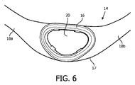
図6によれば、フレーム部材14(ストラップ18及び中央部17)は、ソフト且つ柔軟な材料又は複数の材料で作られている。挿入部16は、開口20内に挿入されるように構成され、剛体又は半剛体である材料で作られている。一実施例では、挿入部16は、デュポン(登録商標)によって製造されるHytrel(登録商標)6356などの熱弾性ポリエステルエラストマー(TPE)で作られているが、これに限定されない。しかしながら、当然、挿入部16は、例えば、開示の概念の範囲から逸脱しなければ、これに限定されないが、任意の適切な硬質熱可塑性樹脂などの他の適切な剛体材料又は半剛体材料で作られることができる。特に、挿入部16において用いられる剛体材料又は半剛体材料は、柔軟な材料で作られるフレーム部材14よりも挿入部16を堅くする。好ましくは、挿入部16は、例えば、これに限定されないが、ステッチ、溶接、接着、又は、オーバーモールドなどの任意の適切な方法を用いて、フレーム部材14に取り付けられることができる。
According to FIG. 6, the frame member 14 (
挿入部16は、図6の実施例に示されるように、単体として設計されてもよく、又は、挿入部16は、図7の実施例に示されるように、噛みあわせられる複数の部材16a及び16bから設計されてもよい。挿入部16は、図6及び図7に示されるように、三角形状を有していてもよく、又は、任意の他の適切な形状を有していてもよい。挿入部16が、図6及び図7に示される三角形状などの独特の形状を持つ場合、クッション部材12は、これらが互いに対して適切に配置された場合にのみ、フレーム部材14と結合されることができ、このことは、患者インタフェース装置8の適切な組み立てを容易にする。
The
挿入部16のために剛体材料又は半剛体材料を用いることは、患者インタフェース装置8を組み立てる患者のためのプロセスを容易にする。また、挿入部16のために剛体材料又は半剛体材料を用いることは、患者インタフェース装置8が適切に組み立てられたことを患者に示すために、クリック音などの正のフィードバックを供給する。
Using a rigid or semi-rigid material for the
図8は、一実施例に従ったクッション部材12の断面を図示している。図8によれば、クッション部材12は、ベース112、2つのステム114、及び、2つのプラットフォーム116を有する本体部110を含む(1つのステム114及び1つのプラットフォーム116のみが図8の断面図に示されている)。ベース112、ステム114、及び、プラットフォーム116は、ともに一体的に形成されている。クッション部材12の本体部110は、ゲル、シリコーン、泡、ゴム、又は、これらの材料の組み合わせなどの、任意の適切な材料から作られることができる。鼻カニューレ26a,26bは、クッション部材12の対応するプラットフォーム116に結合される。
FIG. 8 illustrates a cross-section of the
鼻カニューレ26a,26bによって形成された開口は、クッション部材12の内側に形成されたチャンバ内に患者から空気が流れることを可能にする。クッション部材12の内側の穴領域と配管6との間のエアフローは、クッション部材12において形成された開口111(図10参照)によって促進される。
The openings formed by the
引き続き図8によれば、鼻カニューレ26(26a,26b)は、フラップ132、外側ケース134、内側ケース136、及び、底面キャップ138を含む。フラップ132、外側ケース134、内側ケース136、及び、底面キャップ138は、それぞれ、ゲル、シリコーン、泡、ゴム、又は、これらの材料の組み合わせなどの任意の適切な材料で作られることができる。ある実施例では、フラップ132は、シリコーンから作られる。フラップ132は、ユーザの鼻孔内に挿入されるのに適合される。外側ケース134は、鼻カニューレ26の外側部分に配置され、内側ケース136は、鼻カニューレ26の内側部分に配置される。外側ケース134、内側ケース136、及び、底面キャップ138は、充填材料140で満たされる空間を形成する。充填材料140は、一般的に、ゲル、又は、一般的に、外側ケース134、内側ケース136、及び、底面キャップ138によって形成された空間に適合する他の適切な材料からなる。
Continuing with FIG. 8, the nasal cannula 26 (26 a, 26 b) includes a
充填材料140は、粘弾性ウレタンポリマーを有するゲル物質、又は、弾性材料などの、粘弾性材料であってもよい。また、充填材料140は、液体又は空気であってもよい。ここでは、粘弾性材料なる用語は、変形中、粘性及び弾性が存在する材料であって、結果として、時間依存性の変形を有する材料を意味する。粘弾性材料は、このため、付与される応力の影響の下、変形し、応力が材料から除去された場合、当該材料は、ゆっくりと、瞬時にではなく、少なくとも変形の一部から回復するであろう。ここでは、弾性材料なる用語は、弾性を有するが、変形中、粘性を有さない材料を意味する。弾性材料は、付与される応力の影響の下、変形し、応力が除去されると、本来の状態に瞬時に戻り、これにより、変形の全てから回復する。
クッション部材12は、ユーザが患者インタフェース装置8を着用する場合、ユーザの鼻孔が外側ケース134に対して押し付けられるように適合される。同様に、ベース112とステム114との間の相互作用が、ユーザの鼻孔に対して鼻カニューレ26を押し返すばね力を作る。生成されるばね力の量は、ステム114がベース112内に押されることを促進する。ベース112及びステム114は、約20グラム〜約250グラムの範囲におけるばね力を生成する。当該ばね力は、鼻カニューレ26が、ユーザの鼻孔に適合し、密封を作ることができるように補助する。
The
開示の概念の幾つかの実施形態では、ベース112及びステム114は、約10shA〜約50shAの範囲におけるデュロメータを持つ。図9A及び図9Bにより、ベース112及びステム114の可変厚さが、より詳細に説明される。図示の目的のために、ベース112及びステム114は、第1の領域113と第2の領域115とに分割されている。第1の領域113は、プラットフォーム116に隣接するステム114の端部において開始し、ベース112内に部分的に延在している。ベース112の残りの部分は、第2の領域115を形成している。第1の領域113は、プラットフォーム116に隣接する領域において最も薄く、第2の領域115に隣接する領域において最も厚い。開示の概念の幾つかの実施形態では、第1の領域113におけるクッション部材12の厚さは、約0.4mm〜約1.8mmの厚さの範囲内にある。開示の概念の幾つかの実施形態では、第2の領域115におけるクッション部材12の厚さは、約0.8mm〜約5.0mmの厚さの範囲内にある。
In some embodiments of the disclosed concept, the
クッション部材12は、側壁を通じて圧縮荷重を外縁に移行し、クッション部材12を通じて空気経路から逃がすとともに、ユーザの人中及び隔壁の敏感領域から逃がすアーチ構造を包含する。第2の領域115におけるより大きな厚みは、クッション部材12の全壊に対する抵抗を増加させるクッション部材12のための構造的支持を供給する。クッション部材12を通じてエアフローが十分に阻止され、ステム114がベース112に崩壊する場合に、クッション部材12の全壊が発生する。クッション部材12の壁の厚みは、クッション部材12の弾性における突然遷移を回避する、第2の領域115から第1の領域113に向かう方向において、段階的に減少する。厚みにおける段階的な移行は、圧点のための可能性を緩和し、クッション部材12の適合性の制御を援助する。また、厚みにおける段階的な移行は、距離相関に対する力における鋭い移行なしに、ばね力の制御を援助する。より薄い壁への移行は、クッション部材12の安定性を高める。
The
図8に戻り、窪み142が、外側ケース134の領域において形成されている。窪み142は、外側ケース134の変形を促進するように働き、ユーザの鼻孔によって、圧力が外側ケース134に付与される場合、ユーザの鼻孔の形状に適合することを可能とする。
Returning to FIG. 8, a
図10は、クッション部材12の底側を図示している。クッション部材12の底側は、ユーザが患者インタフェース装置8を着用する場合、ユーザの上唇上に適合し、当てられるように構成されている。ユーザの上唇に当てられることを促進するため、クッション部材12は、上唇接触部118と、上唇解放部120と、を含む。クッション部材12は、上唇接触部118が、ユーザの上唇の中間領域の外側にある領域においてユーザの上唇と接触するように、適合されている。上唇解放部120は、ユーザの上唇の中ほどの領域に付与される圧力を解放し、ユーザの人中(即ち、ユーザの唇と隔壁との間のセクション)に適合するために曲がっている。上唇の中間領域は、上唇のより敏感な領域であり、当該領域に対する圧力を解放することは、ユーザのための快適性を増加する。また、クッション部材12の適合性は、ユーザに合うように形成し、安定性を増加させる低プロファイル設計を供給する。さらに、ユーザの唇に対するクッション部材12の適合性は、上述のクッション部材12の厚みにおける変化と協働して、ユーザが患者インタフェース装置上のヘッドギアアセンブリを締める場合に、クッション部材12が、クッション部材12を通じて空気の経路を崩壊及び妨害しないように補助する。
FIG. 10 illustrates the bottom side of the
開示の概念の幾つかの実施形態では、上唇接触部118及び上唇解放部120は、クッション部材12の他の領域よりも薄い。上唇接触部118及び上唇解放部120のより薄い厚みは、より薄い構造におけるより大きな適合性を持つことによって、ユーザのための更なる快適性を供給し、これにより、弾性を低下させ、より柔軟であることを可能にする。
In some embodiments of the disclosed concept, the
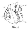
図11は、クッション部材12の上側を図示している。クッション部材12の上側は、ユーザが患者インタフェース装置8を着用する場合に、ユーザの鼻先の近くに配置される。ユーザの鼻先は、敏感な領域であり、過度の圧力は、ユーザにとって不快となる。クッション部材12の上側は、ユーザの鼻に付与される圧力を回避又は和らげるために曲がっており、これにより、ユーザの快適性を増加させる鼻解放部122を含む。
FIG. 11 illustrates the upper side of the
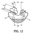
図12は、クッション部材12の上面図である。図12において、D1は、鼻カニューレ26a,26bの先端の中心間の距離である(図12において、鼻カニューレ26bは図示されていない)。開示の概念の幾つかの実施形態において、D1は、約15mm〜約20mmの範囲にあり、好ましくは、約16mm、約17.5mm、約19.5mmのいずれかから選択される。D2は、プラットフォーム416の先端の中心間の距離である。開示の概念の幾つかの実施形態において、D2は、約20mm〜約25mmの範囲にあり、好ましくは、約20.5mm、約22mm、約24mmのいずれかから選択される。D3は、鼻カニューレ26a,26bの高さである。開示の概念の幾つかの実施形態において、D3は、約9mm〜約12mmの範囲にあり、好ましくは、約10.6mmである。D4は、ステム114の高さである。開示の概念の幾つかの実施形態において、D4は、約2mm〜約4mmの範囲にあり、好ましくは、約3mmである。θ1は、鼻カニューレ26a,26bのいずれかの軸と、クッション部材12の中心線に対して平行な線との間の角度である。開示の概念の幾つかの実施形態において、θ1は、約20°〜約24°の範囲にあり、好ましくは、約22°である。開示の概念の幾つかの実施形態において、ステム全体の高さ(即ち、ステムの底から鼻カニューレ26a又は26bの先端までの距離)は、約14mm〜約16mmの範囲にあり、好ましくは、約15.1mmである。
FIG. 12 is a top view of the
図13は、開示の概念の実施例に従ったクッション部材12´の側面図である。クッション部材12´は、第1の材料(約75shAのデュロメータを持つシリコーンなどであるが、これに限定されない)で作られた第1の部分124と、第2の材料(約20shAのデュロメータを持つシリコーンなどであるが、これに限定されない)で作られた第2の部分126と、を含む。第1の材料のデュロメータは、第2の材料のデュロメータよりも高い。クッション部材12´の第1の部分124は、フレーム部材14に結合するクッション部材12´の一部を形成している。クッション部材12´の第1の部分124のためにより高いデュロメータ材料を用いることは、患者インタフェース装置8の組み立ての間、より良好な聴覚及び触覚フィードバックを可能とし、このことは、クッション部材12´及びフレーム部材14が適切に結合される間、ユーザに対してより明確にする。より高いデュロメータ材料は、クッション部材12´とフレーム部材14との間に、よりロバストな密封を作る。さらに、より高いデュロメータ材料は、クッション部材12´の開口111がその形状を保持することを助ける。開口111は、例えば、三角形などの特別な形状を有していてもよく、このことは、クッション部材12´及びフレーム部材14が互いに適切に位置合わせされた場合にのみ、クッション部材12´及びフレーム部材14が結合されることを可能にする。
FIG. 13 is a side view of a cushion member 12 'according to an embodiment of the disclosed concept. The cushion member 12 'includes a
クッション部材12´の第2の部分126は、ユーザの顔に接触するクッション部材12´の一部を形成する。クッション部材12´の第2の部分126のためにより低いデュロメータ材料を用いることは、ユーザに対して更なる快適性を供給し、睡眠中の静的及び動的瞬間などに、クッション部材12´が、ユーザの顔に対してより良好な快適性を与えることを可能にする。 The second portion 126 of the cushion member 12 'forms part of the cushion member 12' that contacts the user's face. Using a lower durometer material for the second portion 126 of the cushion member 12 'provides additional comfort to the user, such as during static and dynamic moments during sleep, etc. It is possible to give better comfort to the user's face.
異なるデュロメータを有する材料を持つクッション部材12´は、開示の概念の範囲から逸脱しなければ、任意の適切な方法を用いて製造されてもよい。ある例では、クッション部材12´のより高いデュロメータ部分が、最初にモールドされ、次いで、クッション部材12´のより低いデュロメータ部分が、より高いデュロメータ部分の上にオーバーモールドされる。他の例では、クッション部材12´のより高いデュロメータの部分とより低いデュロメータの部分との両方が、ツーショットモールド処理を用いて、同時に形成される。 Cushion member 12 'with materials having different durometers may be manufactured using any suitable method without departing from the scope of the disclosed concept. In one example, the higher durometer portion of the cushion member 12 'is first molded and then the lower durometer portion of the cushion member 12' is overmolded over the higher durometer portion. In another example, both the higher and lower durometer portions of the cushion member 12 'are formed simultaneously using a two-shot mold process.
請求項中の括弧内の任意の参照符号は、請求項を限定するものとして解釈されるべきではない。「有する」又は「含む」なる用語は、請求項に挙げられた要素又はステップ以外の要素又はステップの存在を除外しない。幾つかの手段を規定している装置クレームにおいて、これらの手段の幾つかは、全く同一のハードウェアによって実現されてもよい。単数形の要素は、かかる要素が複数存在することを除外しない。幾つかの手段を規定している任意の装置クレームにおいて、これらの手段の幾つかは、全く同一のハードウェア部品によって実現されてもよい。特定の要素が相互に異なる従属項において言及されているという単なる事実は、これらの要素が組み合わせられないということを示すものではない。 Any reference sign between parentheses in the claim should not be construed as limiting the claim. The terms “comprising” or “including” do not exclude the presence of elements or steps other than those listed in a claim. In the device claim defining several means, some of these means may be realized by one and the same piece of hardware. An element in the singular does not exclude the presence of a plurality of such elements. In any device claim defining several means, some of these means may be realized by one and the same hardware component. The mere fact that certain elements are recited in mutually different dependent claims does not indicate that these elements cannot be combined.
現時点で最も実用的且つ好適と考えられる実施態様に基づき例示の目的のために本発明を詳細に記載したが、そのような詳細は専らその目的のためであること、並びに、本発明は開示の実施態様に限定されず、逆に、付属の請求項の精神及び範囲内にある変更及び均等構成を包含することが意図されていることが理解されるべきである。例えば、本発明は、可能な限り、任意の実施態様の1つ又はそれよりも多くの機能を任意の他の実施態様の1つ又はそれよりも多くのの機能と組み合わせ得ることが理解されるべきである。 Although the present invention has been described in detail for purposes of illustration based on the most practical and preferred embodiment at the present time, such details are solely for that purpose and the present invention is not disclosed. It should be understood that the invention is not limited to the embodiments but, conversely, is intended to encompass modifications and equivalent arrangements that fall within the spirit and scope of the appended claims. For example, it is understood that the present invention can combine one or more functions of any embodiment with one or more functions of any other embodiment whenever possible. Should.
Claims (13)
前記クッションと結合する中央部と、前記中央部から延在するストラップと、を持つフレームと、
患者の頭の上にフィットする少なくとも1つの上部と、前記患者の頭の後ろにフィットするリア部と、を含むヘッドギアコンポーネントと、
前記ストラップを前記ヘッドギアコンポーネントに結合する結合機構であって、開口を持つ前記結合機構と、
を有し、
前記ストラップの端部が、前記結合機構の前記開口を通過し、前記フレームの前記中央部に向かう方向において折り畳まれ、前記ストラップに解放可能なように取り付けられ、
前記フレームの前記中央部へ向かって前記ストラップの前記端部を引くことが、前記患者インタフェース装置を締める動作となる、患者インタフェース装置。 A cushion that receives a flow of therapeutic gas;
A frame having a central portion coupled to the cushion, and a strap extending from the central portion;
A headgear component including at least one upper portion that fits over a patient's head and a rear portion that fits behind the patient's head;
A coupling mechanism for coupling the strap to the headgear component, the coupling mechanism having an opening;
Have
An end of the strap passes through the opening of the coupling mechanism and is folded in a direction toward the central portion of the frame and releasably attached to the strap;
The patient interface device, wherein pulling the end of the strap toward the central portion of the frame results in an operation of tightening the patient interface device.
前記フレームが、柔軟な材料で作られ、前記挿入部が、剛体材料又は半剛体材料で作られる、請求項1記載の患者インタフェース装置。 An insertion portion that is inserted into an opening formed in the central portion of the frame;
The patient interface device of claim 1, wherein the frame is made of a flexible material and the insert is made of a rigid or semi-rigid material.
開口を持つフレームと、
前記開口において配置される挿入部と、
を有し、
前記フレームが、柔軟な材料で作られ、前記挿入部が、剛体材料又は半剛体材料で作られる、患者インタフェース装置。 A cushion that receives a flow of therapeutic gas;
A frame with an opening,
An insertion portion disposed in the opening;
Have
A patient interface device, wherein the frame is made of a flexible material and the insert is made of a rigid or semi-rigid material.
Applications Claiming Priority (3)
| Application Number | Priority Date | Filing Date | Title |
|---|---|---|---|
| US201361814853P | 2013-04-23 | 2013-04-23 | |
| US61/814,853 | 2013-04-23 | ||
| PCT/IB2014/060347 WO2014174393A2 (en) | 2013-04-23 | 2014-04-01 | Patient interface device |
Publications (3)
| Publication Number | Publication Date |
|---|---|
| JP2016516520A true JP2016516520A (en) | 2016-06-09 |
| JP2016516520A5 JP2016516520A5 (en) | 2017-04-27 |
| JP6509816B2 JP6509816B2 (en) | 2019-05-08 |
Family
ID=50549374
Family Applications (1)
| Application Number | Title | Priority Date | Filing Date |
|---|---|---|---|
| JP2016509567A Expired - Fee Related JP6509816B2 (en) | 2013-04-23 | 2014-04-01 | Patient interface device |
Country Status (5)
| Country | Link |
|---|---|
| US (1) | US10828449B2 (en) |
| EP (1) | EP2988812B1 (en) |
| JP (1) | JP6509816B2 (en) |
| CN (1) | CN105142705B (en) |
| WO (1) | WO2014174393A2 (en) |
Cited By (1)
| Publication number | Priority date | Publication date | Assignee | Title |
|---|---|---|---|---|
| JP2019521821A (en) * | 2016-07-15 | 2019-08-08 | エンサイト エルエルシー | Nasal interface for CPAP devices |
Families Citing this family (56)
| Publication number | Priority date | Publication date | Assignee | Title |
|---|---|---|---|---|
| USD637279S1 (en) * | 2008-01-11 | 2011-05-03 | Resmed Limited | Strap and yoke for mask |
| DE112010004986T5 (en) | 2009-12-23 | 2013-01-17 | Fisher & Paykel Healthcare Ltd. | Patient interface and head harness |
| USD691257S1 (en) * | 2010-08-23 | 2013-10-08 | Fisher & Paykel Healthcare Limited | Seal for a patient interface |
| US10603456B2 (en) | 2011-04-15 | 2020-03-31 | Fisher & Paykel Healthcare Limited | Interface comprising a nasal sealing portion |
| JP6170036B2 (en) | 2011-04-15 | 2017-07-26 | フィッシャー アンド ペイケル ヘルスケア リミテッド | Interface with rolling nose bridge |
| USD692554S1 (en) | 2011-09-08 | 2013-10-29 | Fisher & Paykel Healthcare Limited | Patient interface assembly |
| SG10202108329RA (en) | 2012-08-08 | 2021-09-29 | Fisher & Paykel Healthcare Ltd | Headgear for patient interface |
| US9950130B2 (en) | 2012-09-04 | 2018-04-24 | Fisher & Paykel Healthcare Limited | Valsalva mask |
| CN105392516B (en) | 2013-04-24 | 2018-05-25 | 费雪派克医疗保健有限公司 | Self-Adjusting Headgear for Patient Interface Incorporated by Reference to Any Priority Application |
| USD770036S1 (en) * | 2013-11-27 | 2016-10-25 | Fisher & Paykel Healthcare Limited | Breathing interface assembly |
| USD771238S1 (en) * | 2014-01-16 | 2016-11-08 | Resmed Limited | Combined plenum, seal and clip module for patient interface |
| NZ630742A (en) * | 2014-05-01 | 2016-02-26 | Resmed Ltd | A patient interface |
| USD771239S1 (en) | 2014-05-08 | 2016-11-08 | Fisher & Paykel Healthcare Limited | Crown strap of a headgear assembly for a breathing interface |
| WO2016009393A1 (en) | 2014-07-18 | 2016-01-21 | Fisher & Paykel Healthcare Limited | Headgear clip arrangement |
| US10828452B2 (en) | 2014-09-16 | 2020-11-10 | Fisher & Paykel Healthcare Limited | Intramold headgear |
| WO2016043603A1 (en) | 2014-09-16 | 2016-03-24 | Fisher & Paykel Healthcare Limited | Headgear assemblies and interface assemblies with headgear |
| SG11201700894UA (en) * | 2014-09-16 | 2017-04-27 | Fisher & Paykel Healthcare Ltd | Headgear for a respiratory mask |
| US10646680B2 (en) | 2014-09-19 | 2020-05-12 | Fisher & Paykel Healthcare Limited | Headgear assemblies and interface assemblies with headgear |
| USD797921S1 (en) | 2014-11-07 | 2017-09-19 | Fisher & Paykel Healthcare Limited | Breathing apparatus |
| CN111773509B (en) | 2015-03-04 | 2023-06-09 | 费雪派克医疗保健有限公司 | Mask system headgear |
| USD799699S1 (en) * | 2015-10-09 | 2017-10-10 | Koninklijke Philips N.V. | Mask frame for CPAP therapy |
| USD784516S1 (en) | 2015-09-25 | 2017-04-18 | Fisher & Paykel Healthcare Limited | Face mask frame |
| USD784515S1 (en) | 2015-09-25 | 2017-04-18 | Fisher & Paykel Healthcare Limited | Headgear |
| USD800895S1 (en) | 2015-09-25 | 2017-10-24 | Fisher & Paykel Healthcare Limited | Face mask cushion |
| AU2017234345B2 (en) | 2016-03-16 | 2022-03-03 | Fisher & Paykel Healthcare Limited | Intra-mould substrate |
| SG10202009029XA (en) | 2016-03-16 | 2020-10-29 | Fisher & Paykel Healthcare Ltd | Directional lock for interface headgear arrangement |
| CN115212417B (en) | 2016-03-16 | 2026-04-10 | 费雪派克医疗保健有限公司 | Strap Components |
| USD882066S1 (en) | 2016-05-13 | 2020-04-21 | Fisher & Paykel Healthcare Limited | Frame for a breathing mask |
| US9914017B2 (en) * | 2016-05-17 | 2018-03-13 | Patrick McKeown | Sports mask system |
| US20210030994A1 (en) * | 2016-06-28 | 2021-02-04 | Koninklijke Philips N.V. | Strap with adhesive silicone adjustment |
| WO2018009080A1 (en) * | 2016-07-08 | 2018-01-11 | Fisher & Paykel Healthcare Limited | A vent for a component of a respiratory therapy system |
| USD829322S1 (en) * | 2016-12-05 | 2018-09-25 | Koninklijke Philips N.V. | Mask |
| CN106693140B (en) * | 2017-01-06 | 2020-02-07 | 北京怡和嘉业医疗科技股份有限公司 | Breathing mask nose pad and breathing mask |
| USD901673S1 (en) | 2017-03-09 | 2020-11-10 | Fisher & Paykel Healthcare Limited | Frame and breathing tube assembly for a nasal mask |
| US12102764B2 (en) | 2017-06-26 | 2024-10-01 | Fisher & Paykel Healthcare Limited | Respiratory mask system |
| SG11201912717QA (en) * | 2017-06-27 | 2020-01-30 | Fisher & Paykel Healthcare Ltd | Respiratory mask system |
| USD855793S1 (en) | 2017-09-20 | 2019-08-06 | Fisher & Paykel Healthcare Limited | Frame for a nasal mask |
| USD875242S1 (en) | 2017-09-20 | 2020-02-11 | Fisher & Paykel Healthcare Limited | Nasal mask and breathing tube set |
| CN118079168A (en) | 2017-12-21 | 2024-05-28 | 费雪派克医疗保健有限公司 | Respiratory mask system |
| EP3762079B1 (en) * | 2018-03-07 | 2025-05-28 | Fisher & Paykel Healthcare Limited | Patient interface |
| CN117618719A (en) | 2018-03-16 | 2024-03-01 | 费雪派克医疗保健有限公司 | Headgear with lock-release engagement mechanism |
| GB2575050B (en) * | 2018-06-26 | 2022-09-14 | Draeger Safety Uk Ltd | Connection apparatus for breathing apparatus |
| WO2020038836A1 (en) * | 2018-08-23 | 2020-02-27 | Koninklijke Philips N.V. | Nasal portion and patient interface device including same cross-reference to related applications |
| AU2019328112B2 (en) | 2018-08-27 | 2025-07-03 | Fisher & Paykel Healthcare Limited | Headgear connectors and headgear for use with or comprising part of a user interface assembly |
| EP3952966B1 (en) * | 2019-04-08 | 2025-09-03 | ResMed Pty Ltd | Seal-forming structure for patient interface |
| US11819612B2 (en) | 2019-10-10 | 2023-11-21 | Fisher & Paykel Healthcare Limited | Respiratory mask system |
| USD1061868S1 (en) | 2019-10-16 | 2025-02-11 | Fisher & Paykel Healthcare Limited | Headgear |
| CN116234473A (en) * | 2020-09-30 | 2023-06-06 | 皇家飞利浦有限公司 | Soft slide through mechanism for CPAP headgear |
| USD1060658S1 (en) * | 2020-12-28 | 2025-02-04 | ResMed Asia Pte. Ltd. | Patient interface |
| USD1109318S1 (en) * | 2022-12-07 | 2026-01-13 | Dcstar Inc | Frame set |
| USD1098410S1 (en) * | 2023-11-10 | 2025-10-14 | Dcstar Inc | Strap |
| USD1122437S1 (en) * | 2024-04-23 | 2026-04-14 | Dcstar Inc | Strap |
| USD1063065S1 (en) * | 2024-04-24 | 2025-02-18 | Dcstar Inc | Strap |
| USD1068062S1 (en) * | 2024-04-24 | 2025-03-25 | Dcstar Inc | Frame set |
| USD1118898S1 (en) * | 2024-06-27 | 2026-03-17 | Dcstar Inc | Frame set |
| USD1120296S1 (en) * | 2024-08-24 | 2026-03-24 | Dcstar Inc | Frame set |
Citations (3)
| Publication number | Priority date | Publication date | Assignee | Title |
|---|---|---|---|---|
| JP2008536565A (en) * | 2005-04-13 | 2008-09-11 | アールアイシー・インベストメンツ・エルエルシー | Double buffer subject interface device |
| US20110265796A1 (en) * | 2010-04-30 | 2011-11-03 | Resmed Limited | Respiratory mask |
| WO2012140514A1 (en) * | 2011-04-15 | 2012-10-18 | Fisher & Paykel Healthcare Limited | Interface comprising a rolling nasal bridge portion |
Family Cites Families (16)
| Publication number | Priority date | Publication date | Assignee | Title |
|---|---|---|---|---|
| US5724965A (en) * | 1995-06-06 | 1998-03-10 | Respironics Inc. | Nasal mask |
| US7856982B2 (en) * | 2004-03-11 | 2010-12-28 | Ric Investments, Llc | Patient interface device |
| CA2890556C (en) | 2006-07-14 | 2018-05-01 | Fisher & Paykel Healthcare Limited | Breathing assistance apparatus |
| ES2573432T3 (en) * | 2006-12-15 | 2016-06-07 | Resmed Ltd. | Respiratory therapy supply |
| NZ589901A (en) | 2008-05-29 | 2013-08-30 | Resmed Ltd | Medical headgear |
| ES2652561T3 (en) * | 2008-10-10 | 2018-02-05 | Fisher & Paykel Healthcare Limited | Nasal pads for a patient interface |
| US8057278B2 (en) * | 2009-04-16 | 2011-11-15 | Warnaco U.S., Inc. | Wire-free brassiere |
| CN105944209B (en) * | 2009-05-29 | 2019-04-19 | 瑞思迈有限公司 | nasal mask system |
| CN102573976A (en) * | 2009-10-23 | 2012-07-11 | 皇家飞利浦电子股份有限公司 | Patient interface device with adjustable headgear and frame |
| NZ707351A (en) * | 2009-11-20 | 2017-02-24 | Resmed Ltd | Mask system |
| BR112012017101A2 (en) | 2010-01-15 | 2016-04-26 | Koninkl Philips Electronics Nv | replaceable nasal cushion for use on a patient interface device, patient interface for use on a patient interface device for dispensing a patient gas stream and patient interface device |
| AU2011308095B2 (en) * | 2010-09-30 | 2014-10-09 | Resmed Limited | Mask system |
| TWI446940B (en) * | 2010-10-13 | 2014-08-01 | Hsiner Co Ltd | Nasal breathing apparatus |
| US20140083427A1 (en) * | 2011-04-18 | 2014-03-27 | Koninklijke Philips N.V. | Patient interface device including pressure relief for deformable compenents |
| FR2974286B1 (en) | 2011-04-22 | 2013-05-17 | Genourob | APPARATUS AND METHOD FOR DETECTING PARTIAL LESION OF CROSS LIGAMENT ANTERIOR KNEE |
| CN106955407B (en) * | 2011-08-22 | 2020-12-29 | 瑞思迈私人有限公司 | Manufactured shaped headbands and masks |
-
2014
- 2014-04-01 US US14/786,002 patent/US10828449B2/en active Active
- 2014-04-01 WO PCT/IB2014/060347 patent/WO2014174393A2/en not_active Ceased
- 2014-04-01 JP JP2016509567A patent/JP6509816B2/en not_active Expired - Fee Related
- 2014-04-01 EP EP14719369.2A patent/EP2988812B1/en active Active
- 2014-04-01 CN CN201480023138.1A patent/CN105142705B/en not_active Expired - Fee Related
Patent Citations (3)
| Publication number | Priority date | Publication date | Assignee | Title |
|---|---|---|---|---|
| JP2008536565A (en) * | 2005-04-13 | 2008-09-11 | アールアイシー・インベストメンツ・エルエルシー | Double buffer subject interface device |
| US20110265796A1 (en) * | 2010-04-30 | 2011-11-03 | Resmed Limited | Respiratory mask |
| WO2012140514A1 (en) * | 2011-04-15 | 2012-10-18 | Fisher & Paykel Healthcare Limited | Interface comprising a rolling nasal bridge portion |
Cited By (1)
| Publication number | Priority date | Publication date | Assignee | Title |
|---|---|---|---|---|
| JP2019521821A (en) * | 2016-07-15 | 2019-08-08 | エンサイト エルエルシー | Nasal interface for CPAP devices |
Also Published As
| Publication number | Publication date |
|---|---|
| CN105142705B (en) | 2019-04-16 |
| EP2988812A2 (en) | 2016-03-02 |
| WO2014174393A2 (en) | 2014-10-30 |
| CN105142705A (en) | 2015-12-09 |
| WO2014174393A3 (en) | 2014-12-31 |
| US10828449B2 (en) | 2020-11-10 |
| JP6509816B2 (en) | 2019-05-08 |
| US20160074611A1 (en) | 2016-03-17 |
| EP2988812B1 (en) | 2019-06-12 |
Similar Documents
| Publication | Publication Date | Title |
|---|---|---|
| JP6509816B2 (en) | Patient interface device | |
| RU2690458C2 (en) | Nasal cannula and patient interface device thereof | |
| US7624735B2 (en) | Cheek-mounted patient interface | |
| JP6023711B2 (en) | Patient interface device with frame assembly having dual Y support structure | |
| US9211388B2 (en) | Mask assembly supporting arrangements | |
| JP6720186B2 (en) | Patient interface device | |
| CN104602746B (en) | Patient Interface Components with Force Limiters | |
| CN107106804B (en) | Adaptive buckling member in a patient interface device | |
| CN105188820B (en) | stabilization mask | |
| US20140261435A1 (en) | Cushion for patient interface with localized region of reduced stiffness | |
| US20140311496A1 (en) | Patient interface having headgear post for clip or strap | |
| US20150157824A1 (en) | Cushion with compression control | |
| AU2011288146A1 (en) | Patient interface device including a dynamic self adjustment mechanism | |
| US9308339B2 (en) | Patient interface having wrap around fabric headgear | |
| US20140083427A1 (en) | Patient interface device including pressure relief for deformable compenents | |
| WO2012077036A2 (en) | Headgear apparatus providing enhanced stability | |
| CN113926039A (en) | Nasal cushion and patient interface device | |
| US20210030994A1 (en) | Strap with adhesive silicone adjustment | |
| AU2012201148B2 (en) | Cheek-mounted patient interface |
Legal Events
| Date | Code | Title | Description |
|---|---|---|---|
| RD04 | Notification of resignation of power of attorney |
Free format text: JAPANESE INTERMEDIATE CODE: A7424 Effective date: 20170214 |
|
| A521 | Request for written amendment filed |
Free format text: JAPANESE INTERMEDIATE CODE: A523 Effective date: 20170324 |
|
| A621 | Written request for application examination |
Free format text: JAPANESE INTERMEDIATE CODE: A621 Effective date: 20170324 |
|
| A977 | Report on retrieval |
Free format text: JAPANESE INTERMEDIATE CODE: A971007 Effective date: 20180219 |
|
| A131 | Notification of reasons for refusal |
Free format text: JAPANESE INTERMEDIATE CODE: A131 Effective date: 20180222 |
|
| A601 | Written request for extension of time |
Free format text: JAPANESE INTERMEDIATE CODE: A601 Effective date: 20180517 |
|
| A521 | Request for written amendment filed |
Free format text: JAPANESE INTERMEDIATE CODE: A523 Effective date: 20180820 |
|
| A02 | Decision of refusal |
Free format text: JAPANESE INTERMEDIATE CODE: A02 Effective date: 20181004 |
|
| A521 | Request for written amendment filed |
Free format text: JAPANESE INTERMEDIATE CODE: A523 Effective date: 20190131 |
|
| A911 | Transfer to examiner for re-examination before appeal (zenchi) |
Free format text: JAPANESE INTERMEDIATE CODE: A911 Effective date: 20190208 |
|
| TRDD | Decision of grant or rejection written | ||
| A01 | Written decision to grant a patent or to grant a registration (utility model) |
Free format text: JAPANESE INTERMEDIATE CODE: A01 Effective date: 20190402 |
|
| A61 | First payment of annual fees (during grant procedure) |
Free format text: JAPANESE INTERMEDIATE CODE: A61 Effective date: 20190403 |
|
| R150 | Certificate of patent or registration of utility model |
Ref document number: 6509816 Country of ref document: JP Free format text: JAPANESE INTERMEDIATE CODE: R150 |
|
| R250 | Receipt of annual fees |
Free format text: JAPANESE INTERMEDIATE CODE: R250 |
|
| R250 | Receipt of annual fees |
Free format text: JAPANESE INTERMEDIATE CODE: R250 |
|
| LAPS | Cancellation because of no payment of annual fees |