JP2016509388A - Display device for displaying autostereoscopic presentation in a rotatable manner - Google Patents
Display device for displaying autostereoscopic presentation in a rotatable manner Download PDFInfo
- Publication number
- JP2016509388A JP2016509388A JP2015548146A JP2015548146A JP2016509388A JP 2016509388 A JP2016509388 A JP 2016509388A JP 2015548146 A JP2015548146 A JP 2015548146A JP 2015548146 A JP2015548146 A JP 2015548146A JP 2016509388 A JP2016509388 A JP 2016509388A
- Authority
- JP
- Japan
- Prior art keywords
- display
- display screen
- parallax barrier
- screen device
- pixel
- Prior art date
- Legal status (The legal status is an assumption and is not a legal conclusion. Google has not performed a legal analysis and makes no representation as to the accuracy of the status listed.)
- Pending
Links
Images




Classifications
-
- H—ELECTRICITY
- H04—ELECTRIC COMMUNICATION TECHNIQUE
- H04N—PICTORIAL COMMUNICATION, e.g. TELEVISION
- H04N13/00—Stereoscopic video systems; Multi-view video systems; Details thereof
- H04N13/30—Image reproducers
- H04N13/302—Image reproducers for viewing without the aid of special glasses, i.e. using autostereoscopic displays
- H04N13/31—Image reproducers for viewing without the aid of special glasses, i.e. using autostereoscopic displays using parallax barriers
- H04N13/315—Image reproducers for viewing without the aid of special glasses, i.e. using autostereoscopic displays using parallax barriers the parallax barriers being time-variant
-
- G—PHYSICS
- G02—OPTICS
- G02B—OPTICAL ELEMENTS, SYSTEMS OR APPARATUS
- G02B30/00—Optical systems or apparatus for producing three-dimensional [3D] effects, e.g. stereoscopic images
- G02B30/20—Optical systems or apparatus for producing three-dimensional [3D] effects, e.g. stereoscopic images by providing first and second parallax images to an observer's left and right eyes
- G02B30/26—Optical systems or apparatus for producing three-dimensional [3D] effects, e.g. stereoscopic images by providing first and second parallax images to an observer's left and right eyes of the autostereoscopic type
- G02B30/30—Optical systems or apparatus for producing three-dimensional [3D] effects, e.g. stereoscopic images by providing first and second parallax images to an observer's left and right eyes of the autostereoscopic type involving parallax barriers
- G02B30/31—Optical systems or apparatus for producing three-dimensional [3D] effects, e.g. stereoscopic images by providing first and second parallax images to an observer's left and right eyes of the autostereoscopic type involving parallax barriers involving active parallax barriers
-
- H—ELECTRICITY
- H04—ELECTRIC COMMUNICATION TECHNIQUE
- H04N—PICTORIAL COMMUNICATION, e.g. TELEVISION
- H04N13/00—Stereoscopic video systems; Multi-view video systems; Details thereof
- H04N13/30—Image reproducers
- H04N13/302—Image reproducers for viewing without the aid of special glasses, i.e. using autostereoscopic displays
- H04N13/31—Image reproducers for viewing without the aid of special glasses, i.e. using autostereoscopic displays using parallax barriers
-
- H—ELECTRICITY
- H04—ELECTRIC COMMUNICATION TECHNIQUE
- H04N—PICTORIAL COMMUNICATION, e.g. TELEVISION
- H04N13/00—Stereoscopic video systems; Multi-view video systems; Details thereof
- H04N13/30—Image reproducers
- H04N13/398—Synchronisation thereof; Control thereof
-
- G—PHYSICS
- G02—OPTICS
- G02B—OPTICAL ELEMENTS, SYSTEMS OR APPARATUS
- G02B27/00—Optical systems or apparatus not provided for by any of the groups G02B1/00 - G02B26/00, G02B30/00
- G02B27/01—Head-up displays
- G02B27/0101—Head-up displays characterised by optical features
- G02B2027/0132—Head-up displays characterised by optical features comprising binocular systems
- G02B2027/0134—Head-up displays characterised by optical features comprising binocular systems of stereoscopic type
-
- G—PHYSICS
- G02—OPTICS
- G02B—OPTICAL ELEMENTS, SYSTEMS OR APPARATUS
- G02B30/00—Optical systems or apparatus for producing three-dimensional [3D] effects, e.g. stereoscopic images
- G02B30/20—Optical systems or apparatus for producing three-dimensional [3D] effects, e.g. stereoscopic images by providing first and second parallax images to an observer's left and right eyes
- G02B30/26—Optical systems or apparatus for producing three-dimensional [3D] effects, e.g. stereoscopic images by providing first and second parallax images to an observer's left and right eyes of the autostereoscopic type
- G02B30/27—Optical systems or apparatus for producing three-dimensional [3D] effects, e.g. stereoscopic images by providing first and second parallax images to an observer's left and right eyes of the autostereoscopic type involving lenticular arrays
-
- H—ELECTRICITY
- H04—ELECTRIC COMMUNICATION TECHNIQUE
- H04N—PICTORIAL COMMUNICATION, e.g. TELEVISION
- H04N13/00—Stereoscopic video systems; Multi-view video systems; Details thereof
- H04N13/30—Image reproducers
- H04N13/302—Image reproducers for viewing without the aid of special glasses, i.e. using autostereoscopic displays
- H04N13/31—Image reproducers for viewing without the aid of special glasses, i.e. using autostereoscopic displays using parallax barriers
- H04N13/312—Image reproducers for viewing without the aid of special glasses, i.e. using autostereoscopic displays using parallax barriers the parallax barriers being placed behind the display panel, e.g. between backlight and spatial light modulator [SLM]
Landscapes
- Engineering & Computer Science (AREA)
- Multimedia (AREA)
- Signal Processing (AREA)
- Physics & Mathematics (AREA)
- General Physics & Mathematics (AREA)
- Optics & Photonics (AREA)
- Testing, Inspecting, Measuring Of Stereoscopic Televisions And Televisions (AREA)
- Controls And Circuits For Display Device (AREA)
- Stereoscopic And Panoramic Photography (AREA)
- Control Of Indicators Other Than Cathode Ray Tubes (AREA)
Abstract
表示装置には、画像データに基づいて画素によって形成されたコンテンツを表示する表示スクリーン装置と、スリット部分及びマスク部分を形成する画素を含み、表示スクリーン装置と連係して裸眼立体提示を表示するように構成されたパララックス・バリアと、表示装置の、表示スクリーン装置の表面に垂直な軸を回転の中心とする基準回転位置からの回転を検知するセンサと、が含まれ得る。表示スクリーン装置の画素構成とパララックス・バリアの画素構成とは、基準回転位置からの表示装置の回転に応じて回転させられ得る。【選択図】図4The display device includes a display screen device that displays content formed by pixels based on image data, and pixels that form slit portions and mask portions, and displays autostereoscopic presentation in conjunction with the display screen device. And a sensor for detecting rotation of the display device from a reference rotation position about the axis perpendicular to the surface of the display screen device as a center of rotation. The pixel configuration of the display screen device and the pixel configuration of the parallax barrier can be rotated according to the rotation of the display device from the reference rotation position. [Selection] Figure 4
Description
本発明は、裸眼立体提示(autostereoscopic presentation)を回転可能に表示するための、表示装置、電子装置、及び、プログラムを格納したコンピュータ可読記憶媒体に関する。 The present invention relates to a display device, an electronic device, and a computer-readable storage medium storing a program for rotatably displaying an autostereoscopic presentation.
裸眼立体表示技術(autostereoscopy)によれば、パララックス・バリアを例えばLCD(液晶ディスプレイ)のような画像供給源の前に配置することによって、観察者が特殊なヘッドギア又は3D(3次元)めがねを着用する必要なく、3次元の奥行の感覚を伴う裸眼立体提示を表示できる。パララックス・バリアによって、観察者の各々の目は異なる画素セットを見ることができ、それにより、視差を介して奥行の感覚が引き起こされる。 According to autostereoscopic technology, an observer can put on special headgear or 3D (three-dimensional) glasses by placing a parallax barrier in front of an image source such as an LCD (liquid crystal display). It is possible to display an autostereoscopic presentation with a sense of 3D depth without having to wear it. The parallax barrier allows each eye of the viewer to see a different set of pixels, thereby causing a sense of depth through parallax.
セル・タイプのパララックス・バリアおよびこれを用いた立体画像表示装置の例は、WO2007/024118A1に提案されている。 An example of a cell-type parallax barrier and a stereoscopic image display device using the same is proposed in WO2007 / 024118A1.
従来型パララックス・バリアを用いる電子装置は、その表示スクリーンが、例えば、観察者に対して、いわゆる「ランドスケープ」(横長)(すなわち、水平方向)の向き、あるいは、「ポートレート」(縦長)(すなわち、垂直方向)の向きにある場合、満足できる裸眼立体提示を提供し得る。しかしながら、観察者が、電子装置の向きを変えて又は回転させて、表示スクリーンの向きをランドスケープ又はポートレートの向き以外の向きに変えた場合、例えば、裸眼立体提示の品質が低下して、観察者は、満足できる3次元の奥行の感覚をもはや体験し得ないかもしれない。 An electronic device using a conventional parallax barrier has a display screen whose orientation is, for example, a so-called “landscape” (landscape) (ie, horizontal) or “portrait” (portrait). Satisfactory autostereoscopic presentation can be provided when in the (ie vertical) orientation. However, if the observer changes the orientation of the electronic device or rotates it to change the orientation of the display screen to a orientation other than the landscape or portrait orientation, for example, the quality of the autostereoscopic presentation is reduced and the observation is performed. One may no longer experience a satisfying sense of 3D depth.
従来のパララックス・バリアを用いる電子装置によれば、観察者は、表示スクリーンが観察者に対して所定の向き、例えば、ランドスケープ又はポートレートの向きにある場合のみしか、裸眼立体提示から満足できる3次元の奥行の感覚を体験し得ない。 With an electronic device using a conventional parallax barrier, the viewer can only be satisfied from the autostereoscopic presentation if the display screen is in a predetermined orientation relative to the viewer, eg, landscape or portrait orientation. You cannot experience the sense of depth in 3D.
したがって、本発明の1つの目的は、観察者に対する表示スクリーンの向きに関係なく、3次元の奥行の感覚を伴う裸眼立体提示を提供可能な表示装置、電子装置、及び、コンピュータ可読記憶媒体を提供することである。 Accordingly, one object of the present invention is to provide a display device, an electronic device, and a computer-readable storage medium capable of providing autostereoscopic presentation with a sense of three-dimensional depth regardless of the orientation of the display screen with respect to the observer. It is to be.
本発明の一態様によれば、表示装置には、画像データに基づいて画素によって形成されたコンテンツを表示する表示スクリーン装置と、スリット部分及びマスク部分を形成する画素を含み、表示スクリーン装置と連係して裸眼立体提示を表示するように構成されたパララックス・バリアと、表示装置の、表示スクリーン装置の表面に垂直な軸を回転の中心とする基準回転位置からの回転を検知するセンサと、が含まれていてもよく、表示スクリーン装置の画素構成とパララックス・バリアの画素構成とは、基準回転位置からの表示装置の回転に応じて回転させられる。 According to one aspect of the present invention, a display device includes a display screen device that displays content formed by pixels based on image data, and a pixel that forms a slit portion and a mask portion, and is associated with the display screen device. A parallax barrier configured to display an autostereoscopic presentation, and a sensor for detecting rotation of the display device from a reference rotation position centered on an axis perpendicular to the surface of the display screen device; The pixel configuration of the display screen device and the pixel configuration of the parallax barrier are rotated according to the rotation of the display device from the reference rotation position.
本発明の別の一態様によれば、電子装置には、画像データに基づいて画素によって形成されたコンテンツを表示する表示スクリーン装置と、スリット部分及びマスク部分を形成する画素を含み、表示スクリーン装置と連係して裸眼立体提示を表示するように構成されたパララックス・バリアとを含む表示部と、表示部の、表示スクリーン装置の表面に垂直な軸を回転の中心とする基準回転位置からの回転を検知するセンサと、表示スクリーン装置の画素構成とパララックス・バリアの画素構成とを、基準回転位置からの表示部の回転に応じて回転させることを含む制御を行う処理装置と、が含まれていてもよい。 According to another aspect of the present invention, an electronic device includes a display screen device that displays content formed by pixels based on image data, and a pixel that forms a slit portion and a mask portion. A display unit including a parallax barrier configured to display an autostereoscopic display in conjunction with the display unit, and a display unit from a reference rotational position with the axis perpendicular to the surface of the display screen device as the center of rotation. A sensor that detects rotation, and a processing device that performs control including rotating the pixel configuration of the display screen device and the pixel configuration of the parallax barrier according to the rotation of the display unit from the reference rotation position. It may be.
本発明の更に別の一態様によれば、表示装置の裸眼立体提示を制御する制御処理工程をコンピュータに実行させるプログラムを記憶した非一時的コンピュータ可読記憶媒体であって、制御処理工程には、表示装置の表示スクリーン装置を制御して、画像データに基づいて画素によって形成されたコンテンツを表示させるステップと、表示スクリーン装置と連係して裸眼立体提示を表示するように構成された、表示装置のパララックス・バリアを制御して、該パララックス・バリアの画素によってスリット部分及びマスク部分を形成させるステップと、表示装置の、表示スクリーン装置の表面に垂直な軸を回転の中心とする基準回転位置からの回転を、センサからの信号に基づいて、検知するステップと、表示スクリーン装置の画素構成とパララックス・バリアの画素構成とを、基準回転位置からの表示装置の回転に応じて回転させるステップと、が含まれる。 According to yet another aspect of the present invention, there is provided a non-transitory computer-readable storage medium storing a program for causing a computer to execute a control processing step for controlling autostereoscopic presentation of a display device. A display device configured to display a content formed by pixels based on image data by controlling a display screen device of the display device, and to display an autostereoscopic presentation in cooperation with the display screen device. A step of controlling the parallax barrier to form a slit portion and a mask portion by the pixels of the parallax barrier, and a reference rotation position of the display device about the axis perpendicular to the surface of the display screen device as a center of rotation Detecting rotation based on the signal from the sensor, and the pixel configuration and parameters of the display screen device. A pixel configuration of box barrier, and rotating in response to rotation of the display device from a reference rotational position, are included.
本発明の目的と利点は、特許請求の範囲の請求項に詳しく記載された構成要素と組み合わせによって、実現され達成されるであろう。 The objects and advantages of the invention will be realized and attained by means of the elements and combinations particularly pointed out in the appended claims.
これまでの概括的な記載と以下の詳細な記載とは、代表的な説明であり、特許請求の範囲の請求項に規定された本発明を制約するものではない。 The foregoing general description and the following detailed description are exemplary and are not restrictive of the invention as defined in the claims.
本発明の上述の及びその他の態様、特徴及び利点は、以下に述べる説明と下記の添付図面とから明らかになるであろう。
以下、本発明の実施形態の種々の態様を説明する。説明の目的のために、十分な理解が得られるよう具体的な構成と詳細な内容を述べる。しかしながら、本発明が、ここに述べられた具体的な詳細な内容の範囲を越えて実施できることも、当業者に明らかであろう。 Hereinafter, various aspects of embodiments of the present invention will be described. For the purpose of explanation, a specific configuration and details are described so that a sufficient understanding can be obtained. However, it will be apparent to those skilled in the art that the present invention may be practiced outside the specific details described herein.
図1は、表示対象を表示するLCD1と、パララックス・バリア2とを有する裸眼立体表示装置を概略的に例示する図である。パララックス・バリアシステムでは、LCD1と観察者との間に配置されたパララックス・バリア2によって、観察者の左目3LはLCD1の左画像画素(すなわち、左画素)Lのみを見て、観察者の右目3RはLCD1の右画像画素(すなわち、右画素)Rのみを見る。その結果、裸眼立体提示が生成され、観察者は3次元の奥行の感覚を体験できる。パララックス・バリア2にはスリットが設けられていてもよく、これらのスリットは、右目3Rが右画像画素Rのみを見て、左目3Lが左画像画素Lのみを見るように、配置されている。図1に例示された画像画素RとLは、例えば、LCD1を形成する画素のマトリックス構成の1つの行に属している。
FIG. 1 is a diagram schematically illustrating an autostereoscopic display device having an
図2はLCDの一部を例示する図であり、図3はパララックス・バリアの一部を例示する図である。LCD1の画素RとLは、図2に例示されたマトリックス構成を有していてもよい。他方、パララックス・バリア2は、図3に例示されたスリット部分2aとマスク部分2bとを有していてもよい。観察者の左目3Lは、スリット部分2aを介して左画素Lのみを見て、マスク部分2bによって遮断された右画素Rは見ない。観察者の右目3Rは、スリット部分2aを介して右画素Rのみを見て、マスク部分2bによって遮断された左画素Lは見ない。
FIG. 2 is a diagram illustrating a part of the LCD, and FIG. 3 is a diagram illustrating a part of the parallax barrier. The pixels R and L of the
裸眼立体表示装置の解像度は、対応する2D(2次元の)表示と比べて、低下することがあり、これは、パララックス・バリア2によって、観察者の各々の目が異なる画素セットを見るようにされるためである。換言すれば、観察者の右目は、仮想の右カメラ画像の右画素Rのみを見て、観察者の左目は、仮想の左カメラ画像の左画素Lのみを見る。したがって、パララックス・バリア2を、マスク部分2bを施して部分的に透過的(すなわち、部分的に非透過的)にするモードと、マスク部分2bを施さないで完全に透過的にするモードと、の間で切り換え可能にすることが有効である場合がある。例えば、LCD1と同様の方法でパララックス・バリア2を液晶材料から形成することによって、パララックス・バリア2をこれらのモード間で切り換える(例えば、ON・OFFにする)ようにしてもよい。パララックス・バリア2は、パララックス・バリア2の画素が透過的な状態と非透過的な状態との間で、画素単位で、切り換えられるように、CPU11(図4)によって駆動されるように構成されている。この意味で、パララックス・バリア2は、いわゆる「アクティブ・パララックス・バリア」と言える。
The resolution of an autostereoscopic display device may be reduced compared to the corresponding 2D (two-dimensional) display, as the
パララックス・バリア2がLCDによって形成される場合、パララックス・バリア2を形成するLCDは、3Dビデオ・コンテンツ又は3Dビデオ・コンテンツを含む複合コンテンツの裸眼立体提示を生成する際には、部分的に透過的(すなわち、部分的に非透過的)にされ、3Dグラフィック・コンテンツの2D表示を行う際には、完全に透過的にされてもよい。3Dビデオ・コンテンツとは、3次元の奥行の感覚が得られる裸眼立体提示を生成するために、LCD1上に表示されてパララックス・バリア2を介して見られるデータを意味する。3Dグラフィック・コンテンツとは、3Dオブジェクトなどの2D表示を行うために、LCD1上に表示されるデータを意味する。複合コンテンツとは、3Dビデオ・コンテンツと3Dグラフィック・コンテンツの両方を含むデータを意味する。
When the
他方、3Dグラフィック・コンテンツを形成する仮想の右カメラ画像及び左カメラ画像の時分割多重化によって、パララックス・バリアシステムの解像度を高めることが可能である。 On the other hand, the resolution of the parallax barrier system can be increased by time-division multiplexing of the virtual right camera image and the left camera image forming 3D graphic content.
図4は、本発明の第1の実施形態による電子装置を例示するブロック図である。図4に例示された電子装置10には、バス19を介して接続された、CPU(中央処理装置)11、記憶部12、表示部13、センサ14、入力装置15、及び、インタフェース(I/F)16が含まれていてもよい。また、RAM(ランダム・アクセス・メモリ)のようなメモリ(図示せず)が、直接接続によって、あるいは、バス19を介して、CPU11に接続されていてもよい。もちろん、CPU11と電子装置10のその他の部分との接続は、直接接続などであってもよく、この接続は、バス19を用いた接続に限定されない。表示部13と入力装置15は、表示部13と入力装置15の両方の機能を一体的に有する単一の装置によって、形成されていてもよい。表示部13と入力装置15の両方の機能を一体的に有する単一の装置の例には、タッチスクリーン・パネルが含まれていてもよい。
FIG. 4 is a block diagram illustrating an electronic device according to the first embodiment of the invention. The
CPU11は、表示部13の表示動作を含む電子装置10の動作を制御する処理装置の一例である。CPU11による表示部13の制御には、裸眼立体提示を生成する際に、仮想の右カメラ画像データに基づいてLCD1の右画素Rを駆動し、仮想の左カメラ画像データに基づいてLCD1の左画素Lを駆動することと、2D表示を行う際に画像データに基づいてLCD1の画素を駆動することと、表示を行う際にバックライト5を駆動する(すなわち、ONにする)ことと、裸眼立体提示を生成する際にパララックス・バリア2の画素を駆動してLCD1の画素RとLに関して部分的に非透過的にすることと、2D表示を行う際にパララックス・バリア2の画素を駆動しないことによってLCD1の画素に関して透過的にすることと、が含まれてもよい。CPU11による表示部13の制御には、後述するように、LCD1とパララックス・バリア2の画素構成を、観察者に対する表示部13の向きに従って、回転させることと、LCD1とパララックス・バリア2の画素を、観察者に対する表示部13の向きに従って、再マッピングすることが更に含まれてもよい。CPU11は、LCD1とパララックス・バリア2とを上述の如く制御するための制御信号を生成してもよい。
The
記憶部12には、CPU11によって実行される1つ又は複数のプログラムが記憶されており、また、3Dビデオ・コンテンツと、3Dグラフィック・コンテンツと、複合コンテンツと、CPU11が実施する演算の間に得られる中間データとを含む、種々のデータが記憶されていてもよい。記憶部12は、半導体メモリ装置か、磁気記録媒体を用いた記憶機構か、光学式記録媒体を用いた光学式記憶機構か、光磁気記録媒体を用いた光磁気記憶機構か、あるいは、そのような装置又は機構の任意の組み合わせによって形成されていてもよい。
The
図5は、第1の実施形態における表示部の一例を概略的に例示する側面図である。図5に例示されているように、表示部13には、バックライト5、LCD1、及び、パララックス・バリア2が含まれていてもよい。バックライト5は、CPU11の制御の下で、表示がされる時にONにされ、表示がされない時にOFFにされてもよい。LCD1には、記憶部12に記憶された画像データによって、あるいは、I/F16を介して受信された画像データによって表される画像(又はコンテンツ)を、CPU11の制御の下で、表示するための画素が含まれている。パララックス・バリア2は、例えば、LCDによって形成されていてもよい。この場合、パララックス・バリア2の画素は、CPU11の制御の下で、裸眼立体提示を生成する際に部分的に透過的(すなわち、部分的に非透過的)にされ、2D表示を行う際に完全に透過的にされてもよい。
FIG. 5 is a side view schematically illustrating an example of the display unit in the first embodiment. As illustrated in FIG. 5, the
図5において、観察者は、表示部13によって表示された表示対象を、パララックス・バリア2の上方から、見る。図5では、バックライト5、LCD1、及び、パララックス・バリア2が連続的に積み重ねられているように例示されているが、バックライト5とLCD1との間にスペース(すなわち、間隙)が形成されていてもよく、また、LCD1とパララックス・バリア2との間にスペース(すなわち、間隙)が形成されていてもよい。
In FIG. 5, the observer views the display target displayed by the
センサ14は、観察者に対する表示部13の向き、すなわち、3次元の姿勢を検知してもよい。説明の便宜上、本例では、観察者は、表示部13の表示スクリーンに対して垂直な目視方向で表示部13を見ると仮定する。表示スクリーンは、互いに重なり合うLCD1とパララックス・バリア2との組み合わせによって形成されていてもよい。したがって、本例では、センサ14は、表示部13の、目視方向に平行な軸を中心とした、回転位置または回転角度を検知して、表示部13の向きを示す向き信号を出力してもよい。センサ14の例には、ジャイロスコープ、あるいは、加速度計と磁力計とを使用する向きセンサなどが含まれていてもよい。
The
入力装置15の例には、観察者(すなわち、ユーザ)が電子装置10にデータ、及び、命令などを入力する時に操作するキーボードなどが含まれていてもよい。前述のように、入力装置15はタッチスクリーン・パネルであってもよく、その結果、表示部13と入力装置15とを単一の装置に一体形成できる。
The example of the
I/F16は、ケーブル・インタフェース、無線インタフェース、あるいは、ケーブル・インタフェースと無線インタフェースとの組み合わせを介して、電子装置10と外部装置(図示せず)との間のインタフェースを提供してもよい。I/F16はインターネットのようなネットワークに接続されてもよく、また、電子装置10は、データ(例えば、3Dビデオ・コンテンツ、3Dグラフィック・コンテンツ、及び、複合コンテンツ)、命令、プログラムなどをそのネットワークを介して受信してもよい。
The I /
プログラムが、コンピュータ、あるいは、CPU11のような処理装置に、パララックス・バリア2とLCD1とを制御する、すなわち、裸眼立体提示を制御する制御処理を実行させてもよい。このようなプログラムは、半導体メモリ装置、磁気記録媒体、光学式記録媒体、及び、光磁気記録媒体を含む任意の適切な不揮発性コンピュータ可読記憶媒体に記憶されていてもよい。更に、このようなプログラムは、表示部13又は電子装置10の全般的な動作を制御する別のプログラムに対するプラグインの形態で提供されてもよい。
The program may cause a computer or a processing device such as the
電子装置10は、ポータブル(携帯可能)であってもよいが、これに限定されない。電子装置10の例には、携帯電話、スマート・フォン、タブレット、PDA(パーソナル・ディジタル・アシスタント)、パーソナル・コンピュータ、ゲーム機、ナビゲーション・システム、セキュリティ・システム、モニタリング・システム、テーマ・パークのアトラクション・システムなどが含まれていてもよい。例えば、テーマ・パークのアトラクション・システムの場合では、表示部は、壁、天井、床などに、表示部の向きを変化させることを可能とする任意の固定装置を介して、固定されてもよい。
The
図6は、スマート・フォンの一例を例示する正面図である。図6に例示されたスマート・フォン101には、通信装置(例えば、送信機と受信機)のようなその他のものに加えて図4に例示された構造体を収容する筐体110が含まれていてもよい。タッチスクリーン・パネル111―1が、表示部13と入力装置15との機能を提供するために、筐体110の1つの表面上に設けられていてもよい。
FIG. 6 is a front view illustrating an example of a smart phone. The
図7は、パーソナル・コンピュータの一例を例示する斜視図である。図7に例示されたPC(パーソナル・コンピュータ)102にはベース部120とリッド(蓋)部121とが含まれていてもよく、これらには通信装置(例えば、モデム)のようなその他のものに加えて図4に例示された構造体が収容されている。ベース部120には、入力装置15の例としてキーボード113が含まれていてもよい。リッド部121は、ベース部120に対する開閉を行ってもよい。図7に例示されているように、リッド部121が開いた状態で、表示部13の表示スクリーン111−2が見えるようにしてもよい。
FIG. 7 is a perspective view illustrating an example of a personal computer. The PC (personal computer) 102 illustrated in FIG. 7 may include a
図8は、電子装置の座標を説明するための図である。この例では、XYZ座標系が採用されている。説明の便宜上、この例では、観察者は、表示部13の表示スクリーン111に垂直な目視方向、すなわち、Z方向に表示部13を見ると仮定する。更に、この例において、センサ14は、XY平面(又はXY平面と平行な平面)上の、Z軸(すなわち、回転の中心軸)を中心とする表示部13の回転位置を検知して、表示部13の向きを示す向き信号を出力すると、仮定する。X方向とY方向とZ方向とは、互いに垂直である。例えば、観察者が表示部13上の提示を見ている間、X方向とY方向は表示部13の表面上を延び、Z方向は観察者に向かって延び得る。
FIG. 8 is a diagram for explaining the coordinates of the electronic device. In this example, an XYZ coordinate system is adopted. For convenience of explanation, in this example, it is assumed that the observer views the
観察者が電子装置10の向きを変え、あるいは、電子装置10を回転させて、表示スクリーン111の向きを変えることによって、LCD1の画素構成及びパララックス・バリア2の画素構成が、それぞれ、図2及び図3に例示された状態から回転させられると、3Dビデオ・コンテンツの裸眼立体提示の品質が低下して、観察者が満足できる3次元の奥行の感覚を、もはや、体験できないことがあり得るが、これは、図1及び図2に関して説明された関係が、もはや、満たされていないためである。LCD1の画素構成とは、仮想の右カメラ画像を表示する右画素Rと仮想の左カメラ画像を表示する左画素Lとが規定された構成を意味してもよい。他方、パララックス・バリア2の画素構成とは、スリット部分2aを形成する画素とマスク部分2bを形成する画素とが規定された構成を意味してもよい。
When the observer changes the orientation of the
したがって、本実施形態において、CPU11は、LCD1の画素構成とパララックス・バリア2の画素構成とを回転させて、センサ14が検知した表示スクリーン111の回転を相殺する。更に詳しく述べると、表示スクリーン111が、例えば、XY平面上でZ軸を中心に反時計回りに45度回転させられると、図1及び図2に関して説明された関係を満たすために、LCD1の画素構成とパララックス・バリア2の画素構成とが、時計回りに45度回転させられて、LCD1の画素R及びLとパララックス・バリア2の画素とが再マッピングされる。換言すれば、LCD1の画素とパララックス・バリア2の画素との再マッピングによって、観察者の左目3Lは、パララックス・バリア2のスリット部分2aを介してLCD1の左画素Lのみを見て、パララックス・バリア2のマスク部分2bによって遮断されたLCD1の右画素Rは見ない一方、この再マッピングによって、観察者の右目3Rは、パララックス・バリア2のスリット部分2aを介してLCD1の右画素Rのみを見て、パララックス・バリア2のマスク部分2bによって遮断されたLCD1の左画素Lは見ない。
Therefore, in the present embodiment, the
LCD1の画素とパララックス・バリア2の画素とが再マッピングされる際に、表示対象の回転させられたコンテンツのサイズは、表示スクリーン111の表示領域内に適合するように、可変的に調節されてもよい。あるいは、その代わりに、表示スクリーン111の表示領域外の回転させられたコンテンツの画像部分が破棄されてもよい。例えば、この再マッピングは、センサ14によって検知されるXY平面上でのZ軸を中心とした表示スクリーン111の回転が0度、90度、180度、及び、270度以外である場合に、行われてもよい。例えば、表示部13が観察者に対してランドスケープ(横長)(すなわち、水平方向)の向き、あるいは、ポートレート(縦長)(すなわち、垂直方向)の向きにある場合に、Z軸を中心とした表示部13の回転位置は0度であってもよい。
When the
図9は、回転させられた状態にあるLCDの画素構成の一部を例示する図である。図9には、表示スクリーン111が、例えば、観察者に対するランドスケープ(横長)(すなわち、水平方向)の向き、あるいは、ポートレート(縦長)(すなわち、垂直方向)の向きから、Z軸を中心としてXY平面上で反時計回りに約45度回転させられた場合についてのLCD1の画素構成の回転させられた状態が例示されている。
FIG. 9 is a diagram illustrating a part of the pixel configuration of the LCD in a rotated state. In FIG. 9, the
図10は、回転させられた状態にあるパララックス・バリアの画素構成の一部を例示する図である。図10には、表示スクリーン111が、例えば、観察者に対するランドスケープ(横長)(すなわち、水平方向)の向き、あるいは、ポートレート(縦長)(すなわち、垂直方向)の向きから、Z軸を中心としてXY平面上で反時計回りに約45度回転させられた場合についてのパララックス・バリア2の画素構成の回転させられた状態が例示されている。
FIG. 10 is a diagram illustrating a part of the pixel configuration of the parallax barrier in a rotated state. In FIG. 10, the
図11は、電子装置の動作を説明するためのフロー・チャートである。例えば、図11に例示された動作は、CPU11がLCD1とパララックス・バリア2とバックライト5とを制御する制御処理を行うプログラムを実行する際に、実施されてもよい。
FIG. 11 is a flowchart for explaining the operation of the electronic apparatus. For example, the operation illustrated in FIG. 11 may be performed when the
図11において、ステップS1で、センサ14から受信された向き信号が、表示スクリーン111(又は表示部13)の、XY平面上でのZ軸を回転の中心とした向き(回転位置又は回転角度)が、例えば0度であってもよい基準の回転位置又は回転角度以外を示しているか否かが、CPUによって判定される。ステップS1の判定結果が「YES」である場合、本処理工程はステップS2に移される。
In FIG. 11, the orientation signal received from the
ステップS2で、CPU11は、センサ14からの向き信号に基づいて、表示スクリーン111の、XY平面上でのZ軸を回転の中心とした回転位置又は回転角度を読み取る。説明の便宜上、この読み取られた、表示スクリーン111の、XY平面上でのZ軸を回転の中心とした回転位置又は回転角度を+rot_z度として、ここで正の符号「+」は反時計回りの回転を示していると仮定する。次に、ステップS3で、CPU11は、演算を行ってLCD1の画素構成とパララックス・バリア2の画素構成とを回転させて表示スクリーン111の回転を相殺する。更に詳しく述べると、ステップS3で、CPU11は、演算を行ってLCD1の画素構成とパララックス・バリア2の画素構成とを−rot_z度だけ回転させて(ここで負の符号「−」は時計回りの回転を示している)、図1及び図2に関して説明された関係を満たすようにLCD1の画素R及びLとパララックス・バリア2の画素とを再マッピングする。LCD1の画素とパララックス・バリア2の画素とを再マッピングした結果、観察者の左目3Lは、パララックス・バリア2のスリット部分2aを介してLCD1の左画素Lのみを見て、観察者の右目3Rは、パララックス・バリア2のスリット部分2aを介してLCD1の右画素Rのみを見る。
In step S <b> 2, the
ステップS4で、CPU11は、表示対象の画像データが3Dビデオ・コンテンツ、3Dグラフィック・コンテンツ、又は、複合コンテンツであるかを判定する。換言すれば、ステップS4で、CPU11は、コンテンツのタイプ(種類)を特定する。表示対象の画像データが3Dグラフィック・コンテンツである場合、本処理工程はステップS5に移される。他方、表示対象の画像データが3Dビデオ・コンテンツ又は複合コンテンツである場合、本処理工程はステップS8に移される。3Dビデオ・コンテンツ用画像データ及び複合コンテンツ用画像データには、仮想の右カメラ画像と仮想の左カメラ画像とが含まれている。他方、3Dグラフィック・コンテンツ用画像データには、仮想の右カメラ画像と仮想の左カメラ画像とは含まれていない。したがって、ステップS4で、CPU11は、仮想の右カメラ画像と仮想の左カメラ画像とが表示対象の画像データ内に存在するか否かを検知することによって、その画像データが3Dビデオ・コンテンツ及び複合コンテンツの一方であるか、あるいは、3Dグラフィック・コンテンツであるかを判定してもよい。表示対象の画像データが、例えば、H.264/AVC規格に準拠している場合、ステレオESIメッセージが右カメラ画像と左カメラ画像とを識別する。したがって、ステップS4で、CPU11は、ステレオESIメッセージが仮想の右カメラ画像と仮想の左カメラ画像とを識別するか否かを検知することによって、表示対象の画像データが3Dビデオ・コンテンツ及び複合コンテンツの一方であるか、あるいは、3Dグラフィック・コンテンツであるかを判定してもよい。
In step S4, the
ステップS5で、CPU11は、3Dグラフィック・コンテンツの表示を回転させるべきか否かを、例えば、デフォルトの設定又は観察者によって入力された設定に基づいて、判定する。ステップS5の判定結果が「YES」である場合、ステップS6で、CPU11は、表示対象の3Dグラフィック・コンテンツを−rot_z度だけ回転させる。ステップS6の後、あるいは、ステップS5の判定結果が「NO」である場合、ステップS7で、CPU11は、パララックス・バリア2を制御して、LCD1の画素に対して完全に透過的になるようにし、本処理工程はステップS11に移される。本例において、ステップS7において、パララックス・バリア2の画素を駆動しない。
In step S5, the
他方、ステップS4で、CPU11が、表示対象の画像データが3Dビデオ・コンテンツ及び複合コンテンツの一方であると判定した場合、ステップS8で、CPU11は、図1及び図2に関して説明された関係を満たすために、LCD1の画素構成を−rot_z度だけ回転させて、パララックス・バリア2の回転させられた画素構成と整合させる。その結果として、LCD1の画素R及びLとパララックス・バリア2の画素とが再マッピングされる。次に、ステップS9で、CPU11は、表示対象の回転させられたコンテンツのサイズを可変的に調節して表示スクリーン111の表示領域内に適合させる。ステップS9のこの調節の際に、CPU11は、表示スクリーン111の表示領域外の回転させられたコンテンツの画像部分を破棄してもよい。次に、ステップS10で、CPU11は、裸眼立体提示を生成するために、パララックス・バリア2の画素を駆動して、LCD1の画素R及びLに対して部分的に非透過的になるようにする。
On the other hand, when the
ステップS7又はステップS10の後、ステップS11で、CPU11は、バックライト5を駆動する(すなわち、ONにする)。あるいは、その代わりに、バックライト5は、電力消費の観点で容認可能であれば、全ステップを通してONに維持されていてもよい。
After step S7 or step S10, in step S11, the
ステップS12で、CPU11は、表示対象のコンテンツに基づいてLCD1を駆動する。3Dビデオ・コンテンツ又は複合コンテンツを表示する際に、CPU11は、裸眼立体提示を生成するために、仮想の右カメラ画像データに基づいてLCD1の右画素Rを駆動し、仮想の左カメラ画像データに基づいてLCD1の左画素Lを駆動する。他方、3Dグラフィック・コンテンツを表示する際に、CPU11は、2D表示を行うために、3Dグラフィック・コンテンツの画像データに基づいて、LCD1の画素を駆動する。
In step S12, the
ステップS12の後、ステップS13で、CPU11は、コンテンツの更新を待つか、あるいは、表示スクリーン111(又は表示部13)の回転位置又は回転角度の変化を待つ。ステップS14で、CPU11は、上記更新、又は、表示スクリーン111の回転位置の変化が起きたか否かを判定し、コンテンツの更新、又は、回転位置の変化が起きて、ステップS14の判定結果が「YES」になった後、本処理工程はステップS1に戻ってもよい。
After step S12, in step S13, the
LCD1、パララックス・バリア2、及び、バックライト5を駆動する順序は、図11に例示された処理工程に従う順序には限定されない。
The order of driving the
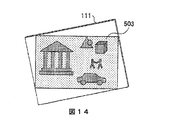
図12から図14は、表示スクリーン上の回転させられた提示の例を説明するための図である。図12は、3Dビデオ・コンテンツについての回転させられた裸眼立体提示を例示する図である。図12には、表示スクリーン111がXY平面上でZ軸を中心にして+rot_z度だけ回転させられて、裸眼立体提示501が、3Dビデオ・コンテンツを−rot_z度だけ回転させて、この回転させられた3Dビデオ・コンテンツのサイズを調節して表示スクリーン111の表示領域内に適合させることによって生成された場合が例示されている。
FIGS. 12 to 14 are diagrams for explaining an example of the rotated presentation on the display screen. FIG. 12 is a diagram illustrating rotated autostereoscopic presentation for 3D video content. In FIG. 12, the
図13は、3Dグラフィック・コンテンツについての回転させられた提示を例示する図である。図13には、表示スクリーン111がXY平面上でZ軸を中心にして+rot_z度だけ回転させられて、3Dグラフィック・コンテンツの2D表示502が、回転させられた表示スクリーン111上に生成された場合が例示されている。図13には、3Dグラフィック・コンテンツが、回転させられた表示スクリーン111に対して回転させられていない例が示されているが、2D表示502は、3Dグラフィック・コンテンツを−rot_z度だけ回転させて、その回転させられた3Dグラフィック・コンテンツのサイズを調節して表示スクリーン111の表示領域内に適合させることによって、なされてもよい。
FIG. 13 is a diagram illustrating a rotated presentation for 3D graphic content. In FIG. 13, when the
図14は、3Dビデオ・コンテンツと3Dグラフィック・コンテンツとを含む複合コンテンツについての回転させられた裸眼立体提示を例示する図である。図14には、表示スクリーン111がXY平面上でZ軸を中心にして+rot_z度だけ回転させられて、複合コンテンツ内の3Dビデオ・コンテンツの裸眼立体提示503が、複合コンテンツを−rot_z度だけ回転させて、その回転させられた複合コンテンツのサイズを調節して表示スクリーン111の表示領域内に適合させることによって、なされた場合が例示されている。
FIG. 14 is a diagram illustrating a rotated autostereoscopic presentation for composite content including 3D video content and 3D graphic content. In FIG. 14, the
上述の第1の実施形態では、パララックス・バリア2は、画像データによって表された画像を表示する画像供給源として、表示スクリーン装置の前に配置されている。しかしながら、パララックス・バリア2は、光透過型表示スクリーン装置が使用される場合に、表示スクリーン装置の後ろに配置されてもよい。図15は、第2の実施形態における表示部の一例を概略的に例示する側面図である。図15では、図5における対応部分と同一である部分が同一の参照番号によって示されており、それらの説明は省略する。
In the first embodiment described above, the
図15に例示された表示部13において、パララックス・バリア2は、表示スクリーン装置として、LCD1の後ろに配置されている。換言すれば、パララックス・バリア2は、LCD1とバックライト5との間に配置されてもよい。この場合、パララックス・バリア2のスリット部分2aを通過したバックライト5からの光は、右画素Rを通過して、観察者の右目3Rによってのみ見られ得る一方、パララックス・バリア2のスリット部分2aを通過したバックライト5からの光は、左画素Lを通過して、観察者の左目3Lによってのみ見られ得る。したがって、この第2の実施形態においても、3次元の奥行の感覚が得られる裸眼立体提示が生成され得る。
In the
図15では、バックライト5、パララックス・バリア2、及び、LCD1が連続的に積み重ねられているように例示されているが、バックライト5とパララックス・バリア2との間にスペース(すなわち、間隙)が形成されていてもよく、また、パララックス・バリア2とLCD1との間にスペース(すなわち、間隙)が形成されていてもよい。
In FIG. 15, the
図16は、第3の実施形態における表示装置を例示するブロック図である。図15では、図4における対応部分と同一である部分が同一の参照番号によって示されており、それらの説明は省略する。 FIG. 16 is a block diagram illustrating a display device according to the third embodiment. 15, parts that are the same as the corresponding parts in FIG. 4 are denoted by the same reference numerals, and description thereof is omitted.
図16に例示された表示装置(又は表示モジュール)130には、バス39を介して接続された制御部31、表示パネル33、センサ34、及び、インタフェース(I/F)36が含まれていてもよい。もちろん、制御部31と表示装置31のその他の部分との接続は、直接接続などであってもよく、この接続は、バス39を用いた接続に限定されない。表示パネル33は、図5又は図15に例示された表示部13の構造を有していてもよい。センサ34は、図4に例示されたセンサ14と同じであってもよい。I/F36は、ケーブル・インタフェース、無線インタフェース、あるいは、ケーブル・インタフェースと無線インタフェースとの組み合わせを介して、表示装置130と外部装置(図示せず)との間のインタフェースを提供してもよい。
A display device (or display module) 130 illustrated in FIG. 16 includes a
制御部31には、表示パネル33のLCD1とパララックス・バリア2とバックライト5とを制御する上述の制御処理を行うための例えば専用ハードウェアのようなハードウェアが含まれていてもよい。あるいは、その代わりに、制御部31は、処理装置と、記憶装置及び/又は例えばRAMのようなメモリとの組み合わせによって形成されてもよく、記憶装置に記憶されたプログラムが、処理装置に、表示パネル33のLCD1とパララックス・バリア2とバックライト5とを制御する上述の制御処理を実行させてもよい。
The
上述の各々の実施形態において、LCD1の画素の解像度とパララックス・バリア2の画素の解像度とは、同じ、あるいは、ほぼ同じであってもよい。しかしながら、3次元の奥行の感覚が得られる裸眼立体提示の満足できる解像度を提供するために、たとえ表示スクリーン111が例えば基準の回転位置又は回転角度からXY平面上でZ軸を中心にして回転させられた場合であっても、パララックス・バリア2の画素の解像度の方がLCD1の画素の解像度より高いことが望ましいこともある。
In each of the embodiments described above, the resolution of the pixels of the
更に、図9と図10から理解され得るが、表示スクリーン111が基準の回転位置又は回転角度から回転させられた場合、垂直方向と水平方向の両方における画素のピッチ(すなわち、間隔)(以下、「画素ピッチ」ともいう)は、図2と図3に例示された画素ピッチに比べて、増大している。解像度は、画素ピッチを低減することによって、向上することがあるので、画素ピッチを比較的小さい値に設定することが望ましいこともある。換言すれば、LCD1の画素の解像度とパララックス・バリア2の画素の解像度とを比較的高くするために、LCD1の画素の画素ピッチとパララックス・バリア2の画素の画素ピッチとを比較的小さい値に設定することが望ましいこともある。
Further, as can be understood from FIGS. 9 and 10, when the
上述の実施形態では、LCDが表示スクリーン装置として使用されているが、LCD以外のディスプレイ、例えば、プラズマ・ディスプレイ、OELD(オーガニック・エレクトロ・ルミネセンス(有機EL)ディスプレイ)などが、画像供給源として使用されてもよい。バックライトとバックライトを制御する処理工程とは、表示スクリーン装置に使用されるディスプレイの種類に応じて、省略してもよい。同様に、上述の実施形態では、LCDがパララックス・バリアとして使用されているが、表示スクリーン装置の画素について、非透過的な画素と透過的な画素とを画素単位で選択的に実現できる装置が、パララックス・バリアとして使用されてもよい。 In the above-described embodiment, an LCD is used as a display screen device. However, a display other than the LCD, for example, a plasma display, an OELD (organic electroluminescence (organic EL) display), or the like is used as an image source. May be used. The backlight and the process of controlling the backlight may be omitted depending on the type of display used in the display screen device. Similarly, in the above-described embodiment, an LCD is used as a parallax barrier, but a device capable of selectively realizing a non-transparent pixel and a transparent pixel in units of pixels as a pixel of a display screen device. May be used as a parallax barrier.
上述の実施形態には、例えば「第1」、「第2」又は「第3」で番号付けをしているが、これらの序数は、実施形態の優先順位を意味するものではない。当業者には、その他の多くの変形形態及び修正形態が明らかであろう。 For example, “first”, “second”, or “third” is numbered in the above-described embodiment, but these ordinal numbers do not mean the priority of the embodiment. Many other variations and modifications will be apparent to those skilled in the art.
ここに列挙された全ての例と条件を示す記載とは、技術促進のために本発明者によって提供された本発明と本概念とを読み手が理解するための手助けとなる教育的な目的で、意図されたものであり、本発明と本概念とは、このような具体的に列挙された例と条件とには限定されないと解釈すべきであり、また、本明細書におけるこのような例の組織的構成は、本発明の優位性及び劣等性を示すことに関係しない。本発明の実施形態を詳細に説明したが、これらの実施形態には、様々な変更、代用、及び、修正が、本発明の精神と権利範囲から逸脱することなく、行え得るであろう。 All examples and conditions listed here are for educational purposes to help readers understand the present invention and the concepts provided by the inventor for technical promotion, It is intended that the invention and the concept should not be construed as limited to such specifically recited examples and conditions, nor are such examples herein described. The organizational structure is not related to showing the superiority and inferiority of the present invention. Although embodiments of the present invention have been described in detail, various changes, substitutions, and modifications may be made to these embodiments without departing from the spirit and scope of the invention.
Claims (7)
画像データに基づいて画素によって形成されたコンテンツを表示する表示スクリーン装置と、
スリット部分及びマスク部分を形成する画素を含み、前記表示スクリーン装置と連係して裸眼立体提示を表示するように構成されたパララックス・バリアと、
前記表示装置の、前記表示スクリーン装置の表面に垂直な軸を回転の中心とする基準回転位置からの回転を検知するセンサと、
を備え、
前記表示スクリーン装置の画素構成と前記パララックス・バリアの画素構成とが、前記基準回転位置からの前記表示装置の前記回転に応じて回転させられる、前記表示装置。 A display device,
A display screen device for displaying content formed by pixels based on image data;
A parallax barrier comprising pixels forming a slit portion and a mask portion and configured to display an autostereoscopic presentation in conjunction with the display screen device;
A sensor for detecting rotation of the display device from a reference rotation position with an axis perpendicular to the surface of the display screen device as the center of rotation;
With
The display device, wherein a pixel configuration of the display screen device and a pixel configuration of the parallax barrier are rotated in accordance with the rotation of the display device from the reference rotation position.
画像データに基づいて画素によって形成されたコンテンツを表示する表示スクリーン装置と、スリット部分及びマスク部分を形成する画素を含み、前記表示スクリーン装置と連係して裸眼立体提示を表示するように構成されたパララックス・バリアと、を含む表示部と、
前記表示部の、前記表示スクリーン装置の表面に垂直な軸を回転の中心とする基準回転位置からの回転を検知するセンサと、
前記表示スクリーン装置の画素構成と前記パララックス・バリアの画素構成とを、前記基準回転位置からの前記表示部の前記回転に応じて回転させることを含む制御を行う処理装置と、
を備えた、前記電子装置。 An electronic device,
A display screen device that displays content formed by pixels based on image data, and a pixel that forms a slit portion and a mask portion, and is configured to display autostereoscopic presentation in conjunction with the display screen device A display unit including a parallax barrier;
A sensor for detecting rotation of the display unit from a reference rotation position with an axis perpendicular to the surface of the display screen device as a center of rotation;
A processing device for performing control including rotating the pixel configuration of the display screen device and the pixel configuration of the parallax barrier according to the rotation of the display unit from the reference rotation position;
The electronic device comprising:
前記表示装置の表示スクリーン装置を制御して、画像データに基づいて画素によって形成されたコンテンツを表示させるステップと、
前記表示スクリーン装置と連係して裸眼立体提示を表示するように構成された、前記表示装置のパララックス・バリアを制御して、該パララックス・バリアの画素によってスリット部分及びマスク部分を形成させるステップと、
前記表示装置の、前記表示スクリーン装置の表面に垂直な軸を回転の中心とする基準回転位置からの回転を、センサからの信号に基づいて、検知するステップと、
前記表示スクリーン装置の画素構成と前記パララックス・バリアの画素構成とを、前記基準回転位置からの前記表示装置の前記回転に応じて回転させるステップと、
が含まれている、非一時的コンピュータ可読記憶媒体。 A non-transitory computer-readable storage medium storing a program for causing a computer to execute a control processing step for controlling autostereoscopic presentation of a display device, wherein the control processing step includes:
Controlling a display screen device of the display device to display content formed by pixels based on image data;
A step of controlling a parallax barrier of the display device configured to display an autostereoscopic display in cooperation with the display screen device, and forming a slit portion and a mask portion by pixels of the parallax barrier; When,
Detecting rotation of the display device from a reference rotation position about an axis perpendicular to the surface of the display screen device based on a signal from a sensor;
Rotating the pixel configuration of the display screen device and the pixel configuration of the parallax barrier according to the rotation of the display device from the reference rotation position;
A non-transitory computer-readable storage medium.
Applications Claiming Priority (1)
| Application Number | Priority Date | Filing Date | Title |
|---|---|---|---|
| PCT/CN2012/087348 WO2014100960A1 (en) | 2012-12-24 | 2012-12-24 | Display unit for rotatably displaying an autostereoscopic presentation |
Publications (1)
| Publication Number | Publication Date |
|---|---|
| JP2016509388A true JP2016509388A (en) | 2016-03-24 |
Family
ID=51019646
Family Applications (1)
| Application Number | Title | Priority Date | Filing Date |
|---|---|---|---|
| JP2015548146A Pending JP2016509388A (en) | 2012-12-24 | 2012-12-24 | Display device for displaying autostereoscopic presentation in a rotatable manner |
Country Status (7)
| Country | Link |
|---|---|
| US (1) | US10412376B2 (en) |
| EP (1) | EP2936807A4 (en) |
| JP (1) | JP2016509388A (en) |
| KR (1) | KR102044055B1 (en) |
| CN (1) | CN104871535B (en) |
| BR (1) | BR112015011996B1 (en) |
| WO (1) | WO2014100960A1 (en) |
Families Citing this family (14)
| Publication number | Priority date | Publication date | Assignee | Title |
|---|---|---|---|---|
| US9554124B1 (en) * | 2014-02-05 | 2017-01-24 | Eos Vision, Inc | Image display with full-depth viewing |
| US9977909B1 (en) | 2015-01-13 | 2018-05-22 | State Farm Mutual Automobile Insurance Company | Selectively obscuring and/or revealing sensitive information in a display of a computing device |
| CN106297611B (en) * | 2015-06-05 | 2021-08-10 | 北京智谷睿拓技术服务有限公司 | Display control method and device |
| CN106297610B (en) | 2015-06-05 | 2020-03-17 | 北京智谷睿拓技术服务有限公司 | Display control method and device |
| CN106291953B (en) | 2015-06-05 | 2019-01-08 | 北京智谷睿拓技术服务有限公司 | display control method and device |
| CN107229884B (en) * | 2016-03-25 | 2024-09-03 | 北京小米移动软件有限公司 | Display method and device and electronic equipment |
| CN109070803B (en) | 2016-04-14 | 2021-10-08 | 金泰克斯公司 | Vehicle display system providing depth information |
| US11002958B2 (en) * | 2017-08-24 | 2021-05-11 | International Business Machines Corporation | Dynamic control of parallax barrier configuration |
| WO2019064233A1 (en) | 2017-09-27 | 2019-04-04 | Gentex Corporation | Full display mirror with accommodation correction |
| CN108898958B (en) * | 2018-07-27 | 2020-09-01 | 深圳市华星光电技术有限公司 | Rotary type spliced screen |
| JP7100523B2 (en) | 2018-07-27 | 2022-07-13 | 京セラ株式会社 | Display devices, display systems and moving objects |
| WO2020031977A1 (en) * | 2018-08-08 | 2020-02-13 | 京セラ株式会社 | Image display device, image display system, and mobile body |
| DE102020103967A1 (en) * | 2020-02-14 | 2021-08-19 | Bayerische Motoren Werke Aktiengesellschaft | Field of view display device with a bright, energy-efficient backlight for a vehicle |
| CN113438465A (en) * | 2021-06-22 | 2021-09-24 | 纵深视觉科技(南京)有限责任公司 | Display adjusting method, device, equipment and medium |
Citations (5)
| Publication number | Priority date | Publication date | Assignee | Title |
|---|---|---|---|---|
| JP2006154809A (en) * | 2004-11-30 | 2006-06-15 | Samsung Sdi Co Ltd | Barrier device, stereoscopic image display device and driving method thereof |
| JP2010278979A (en) * | 2009-06-01 | 2010-12-09 | Nhk Media Technology Inc | Stereoscopic video adjusting apparatus, stereoscopic video adjusting system, and program |
| JP2012039335A (en) * | 2010-08-06 | 2012-02-23 | Sony Corp | Image processing system, image processing method, and program |
| WO2012046686A1 (en) * | 2010-10-04 | 2012-04-12 | シャープ株式会社 | Image display device capable of displaying three-dimensional image, and display control device for controlling display of image |
| JP2012088506A (en) * | 2010-10-19 | 2012-05-10 | Sony Corp | Stereoscopic display device and stereoscopic display method |
Family Cites Families (16)
| Publication number | Priority date | Publication date | Assignee | Title |
|---|---|---|---|---|
| AU2004277273A1 (en) | 2003-09-22 | 2005-04-07 | Gene Dolgoff | Omnidirectional lenticular and barrier-grid image display |
| GB0403932D0 (en) | 2004-02-21 | 2004-03-24 | Koninkl Philips Electronics Nv | Improving image quality in a 3D image display device |
| US7180502B2 (en) | 2004-03-23 | 2007-02-20 | Fujitsu Limited | Handheld device with preferred motion selection |
| GB2418315A (en) * | 2004-09-21 | 2006-03-22 | Sharp Kk | Multiple view display |
| KR100647517B1 (en) * | 2005-08-26 | 2006-11-23 | (주)마스터이미지 | Cell structure parallax-barrier and stereoscopic image display device using the same |
| KR100893616B1 (en) * | 2006-04-17 | 2009-04-20 | 삼성모바일디스플레이주식회사 | Electronic video equipment, 2D / 3D video display device and driving method thereof |
| EP2259163A3 (en) | 2006-08-02 | 2011-03-16 | Research In Motion Limited | System and method for adjusting presentation of moving images on an electronic device according to an orientation of the device |
| US8493323B2 (en) | 2006-08-02 | 2013-07-23 | Research In Motion Limited | System and method for adjusting presentation of moving images on an electronic device according to an orientation of the device |
| JP4719929B2 (en) * | 2009-03-31 | 2011-07-06 | Necカシオモバイルコミュニケーションズ株式会社 | Display device and program |
| KR20110109565A (en) * | 2010-03-31 | 2011-10-06 | 삼성전자주식회사 | Backlight unit, 3D display and 3D image forming method having the same |
| WO2012003181A2 (en) * | 2010-07-02 | 2012-01-05 | Fmc Corporation | Solid forms |
| US20120098931A1 (en) | 2010-10-26 | 2012-04-26 | Sony Corporation | 3d motion picture adaption system |
| CN102466906B (en) * | 2010-11-09 | 2015-02-04 | Tcl集团股份有限公司 | Rotatably-displaying stereoscopic display |
| CN102625112B (en) | 2011-01-28 | 2014-11-05 | 华映科技(集团)股份有限公司 | Stereoscopic display device |
| TW201232039A (en) * | 2011-01-28 | 2012-08-01 | Chunghwa Picture Tubes Ltd | Stereoscopic display device with changeable barrier patterns |
| CN202406235U (en) * | 2011-09-29 | 2012-08-29 | 上海立体数码科技发展有限公司 | Parallax barrier and bidirectional stereo image display device applying the parallax barrier |
-
2012
- 2012-12-24 BR BR112015011996-4A patent/BR112015011996B1/en active IP Right Grant
- 2012-12-24 JP JP2015548146A patent/JP2016509388A/en active Pending
- 2012-12-24 US US14/655,043 patent/US10412376B2/en active Active
- 2012-12-24 WO PCT/CN2012/087348 patent/WO2014100960A1/en not_active Ceased
- 2012-12-24 CN CN201280077593.0A patent/CN104871535B/en active Active
- 2012-12-24 KR KR1020157016709A patent/KR102044055B1/en active Active
- 2012-12-24 EP EP12890761.5A patent/EP2936807A4/en not_active Ceased
Patent Citations (5)
| Publication number | Priority date | Publication date | Assignee | Title |
|---|---|---|---|---|
| JP2006154809A (en) * | 2004-11-30 | 2006-06-15 | Samsung Sdi Co Ltd | Barrier device, stereoscopic image display device and driving method thereof |
| JP2010278979A (en) * | 2009-06-01 | 2010-12-09 | Nhk Media Technology Inc | Stereoscopic video adjusting apparatus, stereoscopic video adjusting system, and program |
| JP2012039335A (en) * | 2010-08-06 | 2012-02-23 | Sony Corp | Image processing system, image processing method, and program |
| WO2012046686A1 (en) * | 2010-10-04 | 2012-04-12 | シャープ株式会社 | Image display device capable of displaying three-dimensional image, and display control device for controlling display of image |
| JP2012088506A (en) * | 2010-10-19 | 2012-05-10 | Sony Corp | Stereoscopic display device and stereoscopic display method |
Also Published As
| Publication number | Publication date |
|---|---|
| US10412376B2 (en) | 2019-09-10 |
| US20150334379A1 (en) | 2015-11-19 |
| EP2936807A4 (en) | 2016-06-08 |
| WO2014100960A1 (en) | 2014-07-03 |
| CN104871535B (en) | 2018-11-06 |
| EP2936807A1 (en) | 2015-10-28 |
| BR112015011996B1 (en) | 2022-11-22 |
| KR20150102013A (en) | 2015-09-04 |
| KR102044055B1 (en) | 2019-11-12 |
| CN104871535A (en) | 2015-08-26 |
| BR112015011996A2 (en) | 2017-07-11 |
Similar Documents
| Publication | Publication Date | Title |
|---|---|---|
| JP2016509388A (en) | Display device for displaying autostereoscopic presentation in a rotatable manner | |
| US9143770B2 (en) | Application programming interface supporting mixed two and three dimensional displays | |
| EP2802958B1 (en) | Mobile display device | |
| KR100786862B1 (en) | Barrier device, 3D image display device and its driving method | |
| US10324736B2 (en) | Transitioning between 2D and stereoscopic 3D webpage presentation | |
| US10257500B2 (en) | Stereoscopic 3D webpage overlay | |
| CN104935916B (en) | Display device | |
| TW201234350A (en) | Display driver integrated circuit, operating method thereof, and user device including the same | |
| WO2024263370A1 (en) | Displays with varying update frequencies for different content types | |
| JP2013098840A (en) | Information processing apparatus, display control method, and program | |
| WO2019150624A1 (en) | Display device and display system | |
| WO2012063789A1 (en) | Display device, method for controlling display device, program and recording medium | |
| EP2803198B1 (en) | 3d display apparatus and method thereof | |
| US20250117077A1 (en) | Display rotation to increase virtual fov for fish tank-style vr system | |
| CN108267860B (en) | Head-mounted display device | |
| JP5349658B2 (en) | Information processing apparatus, information processing method, and program | |
| CN104935906B (en) | Control control method and the device of electronic display unit by packing box | |
| KR101746419B1 (en) | Three dimension image display device and driving method for thereof | |
| JPWO2015156128A1 (en) | Display control apparatus, display control method, and program | |
| TW202123690A (en) | Method for realizing 3D image display, and 3D display device | |
| KR20120000893A (en) | Display device and image control method of display device |
Legal Events
| Date | Code | Title | Description |
|---|---|---|---|
| RD02 | Notification of acceptance of power of attorney |
Free format text: JAPANESE INTERMEDIATE CODE: A7422 Effective date: 20151021 |
|
| A621 | Written request for application examination |
Free format text: JAPANESE INTERMEDIATE CODE: A621 Effective date: 20151105 |
|
| RD04 | Notification of resignation of power of attorney |
Free format text: JAPANESE INTERMEDIATE CODE: A7424 Effective date: 20160627 |
|
| A977 | Report on retrieval |
Free format text: JAPANESE INTERMEDIATE CODE: A971007 Effective date: 20160707 |
|
| A131 | Notification of reasons for refusal |
Free format text: JAPANESE INTERMEDIATE CODE: A131 Effective date: 20160713 |
|
| A601 | Written request for extension of time |
Free format text: JAPANESE INTERMEDIATE CODE: A601 Effective date: 20161006 |
|
| A521 | Request for written amendment filed |
Free format text: JAPANESE INTERMEDIATE CODE: A523 Effective date: 20170112 |
|
| A131 | Notification of reasons for refusal |
Free format text: JAPANESE INTERMEDIATE CODE: A131 Effective date: 20170802 |
|
| A601 | Written request for extension of time |
Free format text: JAPANESE INTERMEDIATE CODE: A601 Effective date: 20171026 |
|
| A521 | Request for written amendment filed |
Free format text: JAPANESE INTERMEDIATE CODE: A523 Effective date: 20180131 |
|
| RD03 | Notification of appointment of power of attorney |
Free format text: JAPANESE INTERMEDIATE CODE: A7423 Effective date: 20180223 |
|
| A02 | Decision of refusal |
Free format text: JAPANESE INTERMEDIATE CODE: A02 Effective date: 20180626 |
|
| A521 | Request for written amendment filed |
Free format text: JAPANESE INTERMEDIATE CODE: A523 Effective date: 20181019 |
|
| A911 | Transfer to examiner for re-examination before appeal (zenchi) |
Free format text: JAPANESE INTERMEDIATE CODE: A911 Effective date: 20181030 |
|
| A912 | Re-examination (zenchi) completed and case transferred to appeal board |
Free format text: JAPANESE INTERMEDIATE CODE: A912 Effective date: 20181214 |
|
| RD03 | Notification of appointment of power of attorney |
Free format text: JAPANESE INTERMEDIATE CODE: A7423 Effective date: 20181220 |
|
| RD04 | Notification of resignation of power of attorney |
Free format text: JAPANESE INTERMEDIATE CODE: A7424 Effective date: 20181227 |
|
| A711 | Notification of change in applicant |
Free format text: JAPANESE INTERMEDIATE CODE: A711 Effective date: 20191111 |
|
| A601 | Written request for extension of time |
Free format text: JAPANESE INTERMEDIATE CODE: A601 Effective date: 20191202 |
|
| A521 | Request for written amendment filed |
Free format text: JAPANESE INTERMEDIATE CODE: A523 Effective date: 20191226 |