JP2016138844A - Strain sensor - Google Patents

Strain sensor Download PDF

Info

Publication number
JP2016138844A
JP2016138844A JP2015014879A JP2015014879A JP2016138844A JP 2016138844 A JP2016138844 A JP 2016138844A JP 2015014879 A JP2015014879 A JP 2015014879A JP 2015014879 A JP2015014879 A JP 2015014879A JP 2016138844 A JP2016138844 A JP 2016138844A
Authority
JP
Japan
Prior art keywords
diaphragm
strain sensor
piezoresistive element
strain
axis direction
Prior art date
Legal status (The legal status is an assumption and is not a legal conclusion. Google has not performed a legal analysis and makes no representation as to the accuracy of the status listed.)
Pending
Application number
JP2015014879A
Other languages
Japanese (ja)
Inventor
将志 宮本
Masashi Miyamoto
将志 宮本
敦雄 竹川
Atsuo Takekawa
敦雄 竹川
Current Assignee (The listed assignees may be inaccurate. Google has not performed a legal analysis and makes no representation or warranty as to the accuracy of the list.)
Panasonic Intellectual Property Management Co Ltd
Original Assignee
Panasonic Intellectual Property Management Co Ltd
Priority date (The priority date is an assumption and is not a legal conclusion. Google has not performed a legal analysis and makes no representation as to the accuracy of the date listed.)
Filing date
Publication date
Application filed by Panasonic Intellectual Property Management Co Ltd filed Critical Panasonic Intellectual Property Management Co Ltd
Priority to JP2015014879A priority Critical patent/JP2016138844A/en
Publication of JP2016138844A publication Critical patent/JP2016138844A/en
Pending legal-status Critical Current

Links

Images

Landscapes

  • Measurement Of Length, Angles, Or The Like Using Electric Or Magnetic Means (AREA)
  • Pressure Sensors (AREA)

Abstract

PROBLEM TO BE SOLVED: To provide a strain sensor capable of obtaining sufficient sensitivity relative to even comparatively low pressure.SOLUTION: A strain sensor includes: a fixing part 110; a diaphragm part 120 connected to the fixing part 110; a piezoresistance 130 provided to the diaphragm part 120; a first beam 121 connected to the fixing part 110; a second beam 122 which is connected to the fixing part 110 and which extends in a direction orthogonal to the first beam 121; and a connection part 123 for connecting the first beam 121 and the second beam 122.SELECTED DRAWING: Figure 1

Description

本開示は、電子機器への入力を検出する検出部を備えた歪センサに関する。   The present disclosure relates to a strain sensor including a detection unit that detects an input to an electronic device.

従来、圧力を検出して動作する情報機器等の電子機器に圧力センサが用いられていた。従来の圧力センサを図5に示す。   Conventionally, pressure sensors have been used in electronic devices such as information devices that operate by detecting pressure. A conventional pressure sensor is shown in FIG.

図5に示すように従来の圧力センサは、中空部を有する支持枠11と、中空部の底面に形成され、圧力の印加により変形するダイヤフラム12と、ダイヤフラム12に設けられていて、ダイヤフラム12の変形により歪むことで圧力を電気的信号として検出する圧力検出部13と、電極14を備えている。ダイヤフラム12は、薄肉領域と、圧力検出部13の一部もしくは全部を含んでおり、薄肉領域の厚みよりも厚くなるように形成された厚肉領域とを有している。   As shown in FIG. 5, the conventional pressure sensor includes a support frame 11 having a hollow portion, a diaphragm 12 formed on the bottom surface of the hollow portion and deformed by application of pressure, and provided on the diaphragm 12. A pressure detection unit 13 that detects pressure as an electrical signal by being distorted by deformation and an electrode 14 are provided. Diaphragm 12 includes a thin region and a thick region that includes part or all of pressure detector 13 and is thicker than the thickness of the thin region.

支持枠11は略四角状に形成されていて、シリコン基板11aの両面には、エッチングする際のマスクとなるSiO2 膜11b、11bが形成されている。   The support frame 11 is formed in a substantially square shape, and SiO2 films 11b and 11b serving as masks for etching are formed on both surfaces of the silicon substrate 11a.

厚肉領域は、ダイヤフラム12の一面もしくは両面に略平面上もしくは突起形状に形成され、ほぼ均一の厚さに形成されたダイヤフラム12に厚肉部を設けることにより形成される。   The thick region is formed on one surface or both surfaces of the diaphragm 12 in a substantially flat or protruding shape, and is formed by providing a thick portion on the diaphragm 12 formed in a substantially uniform thickness.

圧力検出部13は複数のピエゾ抵抗部13a〜13dを有しており、複数のピエゾ抵抗部13a〜13bはそれぞれダイヤフラム12の外周側に配置されている。   The pressure detection unit 13 includes a plurality of piezoresistive units 13 a to 13 d, and the plurality of piezoresistive units 13 a to 13 b are respectively arranged on the outer peripheral side of the diaphragm 12.

次に、図1を参照して、圧力センサデバイスの動作例について説明する。ダイヤフラム12が外部から圧力を受けると、圧力の大きさに応じてダイヤフラム12が変形する。すると、ダイヤフラム12に設けられた圧力検出部13もダイヤフラム12と共に歪み、ダイヤフラム12の外周に配置された複数のピエゾ抵抗13a〜13dの抵抗値が変化する。この抵抗値の変化を計測することにより、圧力センサデバイス10に印加された圧力を計測する。(特許文献1)   Next, an operation example of the pressure sensor device will be described with reference to FIG. When the diaphragm 12 receives pressure from the outside, the diaphragm 12 is deformed according to the magnitude of the pressure. Then, the pressure detection unit 13 provided in the diaphragm 12 is also distorted together with the diaphragm 12, and the resistance values of the plurality of piezoresistors 13a to 13d arranged on the outer periphery of the diaphragm 12 are changed. By measuring the change in the resistance value, the pressure applied to the pressure sensor device 10 is measured. (Patent Document 1)

特開2002−71492号公報JP 2002-71492 A

特許文献1に示される従来の圧力センサでは、圧力を検出したい対象物の厚みや材質によっては、圧力検出部に伝わる歪み量が小さくなってしまい、十分な感度を得ることができないという課題がある。   In the conventional pressure sensor shown in Patent Document 1, depending on the thickness and material of an object whose pressure is to be detected, there is a problem that the amount of strain transmitted to the pressure detection unit becomes small and sufficient sensitivity cannot be obtained. .

そこで本開示は、比較的小さな圧力に対しても十分な感度を得ることができる歪センサを提供することを目的とする。   Therefore, an object of the present disclosure is to provide a strain sensor that can obtain sufficient sensitivity even with a relatively small pressure.

上記課題を解決するために本開示は、固定部と、前記固定部に接続されたダイヤフラム部と、前記ダイヤフラム部に設けられたピエゾ抵抗を有し、前記固定部に接続された第1の梁と、前記固定部に接続され前記第1の梁と直交する方向に延在した第2の梁と、前記第1の梁と前記第2の梁とを接続する接続部とを有した構成とした。   In order to solve the above-described problem, the present disclosure includes a fixed portion, a diaphragm portion connected to the fixed portion, and a piezoresistor provided in the diaphragm portion, and a first beam connected to the fixed portion. A second beam connected to the fixed portion and extending in a direction perpendicular to the first beam, and a connection portion connecting the first beam and the second beam; did.

歪センサのダイヤフラム部を第1の梁と第2の梁が直交した十字形状とし、ダイヤフラム部の端部に固定部を設ける構造にすることで、ダイヤフラム部の断面積を小さくすることが可能となる。ピエゾ抵抗に伝わる歪み量は、ダイヤフラム部の断面積と反比例関係にあることから、断面積を小さくすることによって、検出感度を向上させることが可能となる。   By making the diaphragm part of the strain sensor into a cross shape in which the first beam and the second beam are orthogonal to each other, and by providing a fixed part at the end of the diaphragm part, the cross-sectional area of the diaphragm part can be reduced. Become. Since the amount of distortion transmitted to the piezoresistor is inversely proportional to the cross-sectional area of the diaphragm portion, detection sensitivity can be improved by reducing the cross-sectional area.

本開示の歪センサの平面図Plan view of the strain sensor of the present disclosure 同歪センサAA線断面図Cross section of the same strain sensor AA line 同歪センサのBB線断面図BB line cross section of the same strain sensor 同歪センサに加わる応力を示す図Diagram showing stress applied to the strain sensor 従来の圧力センサを示す図Diagram showing a conventional pressure sensor

(実施の形態1)
以下に、本開示の歪センサの一実施の形態を、添付図面を用いながら詳細に説明する。
(Embodiment 1)
Hereinafter, an embodiment of a strain sensor of the present disclosure will be described in detail with reference to the accompanying drawings.

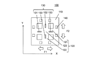
図1は、本開示の一実施の形態における歪センサの構成を示している。歪センサ100は、固定部110と、固定部110に接続されたダイヤフラム部120とを有している。固定部110とダイヤフラム部120はシリコンにより形成されている。ダイヤフラム部120はX軸方向に延在した第1の梁121と、X軸方向と直交しY軸方向に延在した第2の梁122と、第1の梁121と第2の梁122とを接続する接続部123とを有し、第1の梁121と、第2の梁122の上部にはピエゾ抵抗130と、電極140とが設けられている。第1の梁121と第2の梁122は夫々接続部123を挟んで対になって設けられている。固定部110は枠状に形成されており、固定部110のX軸方向の中央部に第1の梁121が接続され、固定部110のY軸方向の中央部に第2の梁122が接続されている。歪センサ100は固定部110で歪みを測定する対象の起歪体(図示せず)に接続されており、起歪体に生じた歪みを測定することができる。なお、一実施の形態において固定部110は枠状に形成されているがこの限りではなく、例えば、第1の梁121と第2の梁122を夫々支持する直方体形状の固定部110を4つ設けても良い。ただし、一実施の形態のように、固定部110を枠形状に形成した方が、歪センサ100の耐久性を向上させることができる。   FIG. 1 illustrates a configuration of a strain sensor according to an embodiment of the present disclosure. The strain sensor 100 has a fixed part 110 and a diaphragm part 120 connected to the fixed part 110. The fixed part 110 and the diaphragm part 120 are made of silicon. The diaphragm 120 includes a first beam 121 extending in the X-axis direction, a second beam 122 orthogonal to the X-axis direction and extending in the Y-axis direction, and the first beam 121 and the second beam 122. And a piezoresistor 130 and an electrode 140 are provided on top of the first beam 121 and the second beam 122. The first beam 121 and the second beam 122 are provided in pairs with the connecting portion 123 interposed therebetween. The fixed portion 110 is formed in a frame shape, and the first beam 121 is connected to the central portion of the fixed portion 110 in the X-axis direction, and the second beam 122 is connected to the central portion of the fixed portion 110 in the Y-axis direction. Has been. The strain sensor 100 is connected to a strain generating body (not shown) whose strain is measured by the fixed portion 110, and can measure strain generated in the strain generating body. In the embodiment, the fixing portion 110 is formed in a frame shape. However, the present invention is not limited to this. For example, the four fixing portions 110 having a rectangular parallelepiped shape that respectively support the first beam 121 and the second beam 122 are provided. It may be provided. However, the durability of the strain sensor 100 can be improved by forming the fixing portion 110 in a frame shape as in the embodiment.

次に、歪センサ100の製造方法の一例について説明する。シリコン基板をエッチング加工することによって固定部110及びダイヤフラム部120を形成する。その後、イオン注入により、ダイヤフラム部120にピエゾ抵抗130を形成する。   Next, an example of a method for manufacturing the strain sensor 100 will be described. The fixing part 110 and the diaphragm part 120 are formed by etching the silicon substrate. Thereafter, a piezoresistor 130 is formed in the diaphragm 120 by ion implantation.

図2は、図1における歪センサ100のA−A線断面図である。固定部110の厚みは、ダイヤフラム部120の厚みよりも大きくなるように形成されており、固定部110の厚み及びダイヤフラム部120の厚みは、それぞれがほぼ均一になるように形成されている。   FIG. 2 is a cross-sectional view of the strain sensor 100 in FIG. The thickness of the fixing part 110 is formed so as to be larger than the thickness of the diaphragm part 120, and the thickness of the fixing part 110 and the thickness of the diaphragm part 120 are formed so as to be substantially uniform.

ダイヤフラム部120には、第1のピエゾ抵抗素子131、第2のピエゾ抵抗素子132、第3のピエゾ抵抗素子133、第4のピエゾ抵抗素子134からなるピエゾ抵抗130が設けられている。ダイヤフラム部120が変形するとピエゾ抵抗130の歪抵抗値が変化する。第1のピエゾ抵抗素子131、第2のピエゾ抵抗素子132、第3のピエゾ抵抗素子133、第4のピエゾ抵抗素子134によってブリッジ回路が形成されている。このピエゾ抵抗130に対し基準電圧を印加したときに、起歪体から荷重が印加されると、X軸方向に引っ張り応力F1が印加され、それに追従する形でY軸方向に圧縮応力F2が印加される。これにより、第1の梁121がX軸方向に伸びるように変形し、第2の梁122がY軸方向に縮むように変形する。ダイヤフラム部120の変形によってピエゾ抵抗130の抵抗値が変化し、この抵抗値の変化をブリッジ回路から出力される電圧変化として電極140を介して測定することで、起歪体に加えられた歪みを測定することができる。   The diaphragm unit 120 is provided with a piezoresistor 130 including a first piezoresistive element 131, a second piezoresistive element 132, a third piezoresistive element 133, and a fourth piezoresistive element 134. When the diaphragm 120 is deformed, the strain resistance value of the piezoresistor 130 changes. The first piezoresistive element 131, the second piezoresistive element 132, the third piezoresistive element 133, and the fourth piezoresistive element 134 form a bridge circuit. When a reference voltage is applied to the piezoresistor 130 and a load is applied from the strain generating body, a tensile stress F1 is applied in the X-axis direction, and a compressive stress F2 is applied in the Y-axis direction so as to follow it. Is done. As a result, the first beam 121 is deformed so as to extend in the X-axis direction, and the second beam 122 is deformed so as to be contracted in the Y-axis direction. The resistance value of the piezoresistor 130 changes due to the deformation of the diaphragm section 120, and the change in the resistance value is measured as a voltage change output from the bridge circuit via the electrode 140. Can be measured.

図3は、図1における歪センサ100のB−B線断面図である。図3に示すように、ダイヤフラム部120を第1の梁121と、第2の梁122と、接続部123とを接続することによって形成することで、第1の梁121または第2の梁122が延在した方向と直交する方向のダイヤフラム部120のピエゾ抵抗130が設けられた部分の断面積が小さくなる。起歪体から圧力が加えられたときのダイヤフラム部120の歪量は断面積の大きさに反比例するため、従来の圧力センサのようにダイヤフラム部が固定部の内側全面に設けられた構造に比べ、一実施の形態の歪センサ100は圧力が加えられたときのダイヤフラム部120の歪量を大きくすることができる。これにより、ピエゾ抵抗130に加わる歪量が大きくなり、歪センサ100の検出感度を向上させることができる。   FIG. 3 is a cross-sectional view of the strain sensor 100 in FIG. As shown in FIG. 3, the diaphragm portion 120 is formed by connecting a first beam 121, a second beam 122, and a connection portion 123, so that the first beam 121 or the second beam 122 is formed. The cross-sectional area of the portion provided with the piezoresistor 130 of the diaphragm portion 120 in the direction orthogonal to the direction in which the stub extends is reduced. Since the amount of strain of the diaphragm 120 when pressure is applied from the strain generating body is inversely proportional to the size of the cross-sectional area, compared to a structure in which the diaphragm is provided on the entire inner surface of the fixed portion like a conventional pressure sensor. The strain sensor 100 according to the embodiment can increase the strain amount of the diaphragm portion 120 when pressure is applied. Thereby, the amount of strain applied to the piezoresistor 130 increases, and the detection sensitivity of the strain sensor 100 can be improved.

第1の梁121には第1のピエゾ抵抗素子131と第3のピエゾ抵抗素子133がX軸方向に延在するように配置され、第2の梁122には第2のピエゾ抵抗素子132と第4のピエゾ抵抗素子134がY軸方向に延在するように配置されている。すなわち、第1のピエゾ抵抗素子131、第2のピエゾ抵抗素子132、第3のピエゾ抵抗素子133、第4のピエゾ抵抗素子134の長手方向が接続部を向くように配置されている。   A first piezoresistive element 131 and a third piezoresistive element 133 are arranged on the first beam 121 so as to extend in the X-axis direction, and a second piezoresistive element 132 and a second piezoresistive element 132 are arranged on the second beam 122. The fourth piezoresistive element 134 is arranged so as to extend in the Y-axis direction. That is, the first piezoresistive element 131, the second piezoresistive element 132, the third piezoresistive element 133, and the fourth piezoresistive element 134 are arranged so that the longitudinal directions thereof face the connection portion.

この様にピエゾ抵抗130を配置することにより、起歪体に生じた歪によって、ダイヤフラム部120に生じた歪の検出感度を向上させることができている。例えば、起歪体から歪センサ100に対してX軸方向に引張応力F1が印加されると、起歪体のY軸方向に対しては圧縮応力F2が印加される。このとき、長手方向がX軸方向になるように配置された第1のピエゾ抵抗素子131と第3のピエゾ抵抗素子133には引張応力が加わり、抵抗値が上昇する。一方、長手方向がY軸方向になるように配置された第2のピエゾ抵抗素子132と第4のピエゾ抵抗素子134には圧縮応力が印加され、抵抗値が低下する。ここで、第1のピエゾ抵抗素子131と第2のピエゾ抵抗素子132、第3のピエゾ抵抗素子133と第4のピエゾ抵抗素子134を夫々ペアとしてブリッジ回路を形成することで圧力センサの検出感度を向上させることができる。また、第1のピエゾ抵抗素子131と第4のピエゾ抵抗素子134、第2のピエゾ抵抗素子132と第3のピエゾ抵抗素子133を夫々ペアにしてブリッジ回路を形成しても同様に歪センサ100の検出感度を向上させることができる。   By arranging the piezoresistor 130 in this way, the detection sensitivity of the distortion generated in the diaphragm 120 due to the distortion generated in the strain generating body can be improved. For example, when a tensile stress F1 is applied from the strain generating body to the strain sensor 100 in the X-axis direction, a compressive stress F2 is applied to the Y-axis direction of the strain generating body. At this time, tensile stress is applied to the first piezoresistive element 131 and the third piezoresistive element 133 arranged so that the longitudinal direction is in the X-axis direction, and the resistance value is increased. On the other hand, compressive stress is applied to the second piezoresistive element 132 and the fourth piezoresistive element 134 that are arranged so that the longitudinal direction is in the Y-axis direction, and the resistance value decreases. Here, the first piezoresistive element 131 and the second piezoresistive element 132, and the third piezoresistive element 133 and the fourth piezoresistive element 134 are paired to form a bridge circuit, thereby detecting the sensitivity of the pressure sensor. Can be improved. Further, even if a bridge circuit is formed by pairing the first piezoresistive element 131 and the fourth piezoresistive element 134, and the second piezoresistive element 132 and the third piezoresistive element 133, the strain sensor 100 is similarly formed. Detection sensitivity can be improved.

この様に、第1のピエゾ抵抗素子131と第3のピエゾ抵抗素子133を長手方向がX軸方向となるように配置し、第2のピエゾ抵抗素子132と第4のピエゾ抵抗素子134を長手方向がY軸方向となるように配置することで起歪体に生じた歪の検出感度を向上させることができる。   In this way, the first piezoresistive element 131 and the third piezoresistive element 133 are arranged so that the longitudinal direction is the X-axis direction, and the second piezoresistive element 132 and the fourth piezoresistive element 134 are longitudinally arranged. By arranging the direction so as to be in the Y-axis direction, it is possible to improve the detection sensitivity of the strain generated in the strain generating body.

図1に示すように、ダイヤフラム部120は、第1の梁121と第2の梁122の長さが等しく、第1の梁121と第2の梁122のそれぞれの中点で交わるように形成されている。また、第1のピエゾ抵抗素子131と第3のピエゾ抵抗素子133とは第1の梁121の固定部110と接続部123との間の中心部分に配置され、第2のピエゾ抵抗素子132と第4のピエゾ抵抗素子134とは第2の梁122の固定部110と接続部123との間の中心部分に配置されている。このような構造にすることで、歪センサ100は、X軸方向とY軸方向に夫々が線対称な構造となる。このような構造にすることで、歪センサ100の温度変化による膨張や収縮によって生じる出力変動をキャンセルすることができ、検出精度を向上させることができる。   As shown in FIG. 1, the diaphragm 120 is formed such that the first beam 121 and the second beam 122 have the same length and intersect at the midpoints of the first beam 121 and the second beam 122. Has been. In addition, the first piezoresistive element 131 and the third piezoresistive element 133 are disposed in the central portion between the fixed portion 110 and the connection portion 123 of the first beam 121, and the second piezoresistive element 132 and The fourth piezoresistive element 134 is disposed in the central portion between the fixed portion 110 and the connecting portion 123 of the second beam 122. By adopting such a structure, the strain sensor 100 has a structure that is line-symmetric with respect to the X-axis direction and the Y-axis direction. With such a structure, output fluctuations caused by expansion and contraction due to temperature changes of the strain sensor 100 can be canceled, and detection accuracy can be improved.

また、電極140は、歪量の測定に必要な電極、例えば基準電圧の印加電極や出力電圧の検出電極、GND電極が設けられており、更にダミー電極を形成することで、固定部110のそれぞれの辺に形成される電極の数を同じにすることができる。このダミー電極の配置は、歪センサ100の中心を第1の梁121と第2の梁122に対して夫々が線対称になるように形成されている。   In addition, the electrode 140 is provided with electrodes necessary for measuring the amount of strain, for example, a reference voltage application electrode, an output voltage detection electrode, and a GND electrode. The number of electrodes formed on the sides can be the same. The arrangement of the dummy electrodes is formed so that the center of the strain sensor 100 is symmetrical with respect to the first beam 121 and the second beam 122.

次に、実施の形態の歪センサの効果について説明する。   Next, the effect of the strain sensor of the embodiment will be described.

従来の歪センサでは、温度変化等の環境変化の影響があった場合、ダイヤフラム部が変形し、温度変化によるダイヤフラム部の変形を歪センサに応力が加わったものとして検出してしまうことがある。しかしながら、本開示の歪センサ100では、温度変化の影響を低減することができている。   In a conventional strain sensor, when there is an influence of environmental changes such as a temperature change, the diaphragm part may be deformed and the deformation of the diaphragm part due to the temperature change may be detected as a stress applied to the strain sensor. However, the strain sensor 100 according to the present disclosure can reduce the influence of temperature change.

起歪体から歪センサ100に荷重が印加された場合、ダイヤフラム部120にX軸方向に引張応力F1が加わり、Y軸方向に圧縮応力F2が加わる。一方、温度変化によってダイヤフラム部120に応力が加わった場合、歪センサ100の温度が上昇した場合、ダイヤフラム部120が膨張するためダイヤフラム部120のX軸方向、Y軸方向に加わる応力は共に引張応力(膨張)となる。また、温度が下降した場合は、ダイヤフラム部120のX軸方向、Y軸方向に加わる応力は共に圧縮応力(収縮)となる。ここで、ピエゾ抵抗130は、X軸方向とY軸方向に直交するように配置してある為、ピエゾ抵抗130には同じ応力が加わる。これにより、温度変化による歪センサ100の変形による出力変化をキャンセルすることができる。   When a load is applied from the strain generating body to the strain sensor 100, a tensile stress F1 is applied to the diaphragm 120 in the X-axis direction, and a compressive stress F2 is applied in the Y-axis direction. On the other hand, when stress is applied to the diaphragm portion 120 due to temperature change, when the temperature of the strain sensor 100 rises, the diaphragm portion 120 expands, and therefore the stress applied to the diaphragm portion 120 in the X-axis direction and Y-axis direction is both tensile stress. (Expansion). When the temperature decreases, the stress applied to the diaphragm portion 120 in the X-axis direction and the Y-axis direction both becomes compressive stress (shrinkage). Here, since the piezoresistor 130 is disposed so as to be orthogonal to the X-axis direction and the Y-axis direction, the same stress is applied to the piezoresistor 130. Thereby, the output change by the deformation | transformation of the strain sensor 100 by a temperature change can be canceled.

さらに、歪センサ100は、歪センサ100の中心に対してX軸方向とY軸方向に夫々が線対称である。このため、第1のピエゾ抵抗素子131、第2のピエゾ抵抗素子132、第3のピエゾ抵抗素子133、第4のピエゾ抵抗素子134に加わる応力の大きさは同じになる。このことから、温度変化による歪センサ100の変形による出力変化をより効果的にキャンセルすることができる。   Further, the strain sensor 100 is symmetrical with respect to the center of the strain sensor 100 in the X axis direction and the Y axis direction. For this reason, the magnitudes of stress applied to the first piezoresistive element 131, the second piezoresistive element 132, the third piezoresistive element 133, and the fourth piezoresistive element 134 are the same. From this, an output change due to deformation of the strain sensor 100 due to a temperature change can be canceled more effectively.

本開示による歪センサは、検出感度に優れている為、入力により多様な制御を簡単な操作で行うことのできる情報機器や、生じた歪により動作を制御する冷蔵庫、洗濯機等の電子機器に有用である。   Since the strain sensor according to the present disclosure has excellent detection sensitivity, it can be used in information devices that can perform various controls by simple operations by input, and electronic devices such as refrigerators and washing machines that control operations based on the generated strain. Useful.

100 歪センサ
110 固定部
120 ダイヤフラム部
121 第1の梁
122 第2の梁
123 接続部
130 ピエゾ抵抗
131 第1のピエゾ抵抗素子
132 第2のピエゾ抵抗素子
133 第3のピエゾ抵抗素子
134 第4のピエゾ抵抗素子
140 電極
DESCRIPTION OF SYMBOLS 100 Strain sensor 110 Fixed part 120 Diaphragm part 121 1st beam 122 2nd beam 123 Connection part 130 Piezoresistor 131 1st piezoresistive element 132 2nd piezoresistive element 133 3rd piezoresistive element 134 4th Piezoresistive element 140 electrode

Claims (5)

固定部と、
前記固定部に接続されたダイヤフラム部と、
前記ダイヤフラム部に設けられたピエゾ抵抗を有し、
前記固定部に接続された第1の梁と、
前記固定部に接続され前記第1の梁と直交する方向に延在した第2の梁と、
前記第1の梁と前記第2の梁とを接続する接続部とを有した歪センサ。
A fixed part;
A diaphragm portion connected to the fixed portion;
Having a piezoresistor provided in the diaphragm portion;
A first beam connected to the fixed part;
A second beam connected to the fixed portion and extending in a direction perpendicular to the first beam;
A strain sensor having a connection portion connecting the first beam and the second beam.
前記第1の梁と前記第2の梁の長さが等しい請求項1に記載の歪センサ。 The strain sensor according to claim 1, wherein the first beam and the second beam have the same length. 前記ピエゾ抵抗は、
前記第1の梁に前記第1の梁が延在した方向に配置され、
前記第2の梁に前記第2の梁が延在した方向に配置されている請求項1に記載の歪センサ。
The piezoresistor is
The first beam is disposed in a direction in which the first beam extends;
The strain sensor according to claim 1, wherein the second beam is disposed in a direction in which the second beam extends.
前記ピエゾ抵抗は、前記第1の梁と前記第2の梁の交点と、前記固定部との中心に配置する請求項1に記載の歪センサ。 2. The strain sensor according to claim 1, wherein the piezoresistor is arranged at the center of the intersection of the first beam and the second beam and the fixed portion. 前記固定部が枠状に形成される請求項1に記載の歪センサ。 The strain sensor according to claim 1, wherein the fixing portion is formed in a frame shape.
JP2015014879A 2015-01-29 2015-01-29 Strain sensor Pending JP2016138844A (en)

Priority Applications (1)

Application Number Priority Date Filing Date Title
JP2015014879A JP2016138844A (en) 2015-01-29 2015-01-29 Strain sensor

Applications Claiming Priority (1)

Application Number Priority Date Filing Date Title
JP2015014879A JP2016138844A (en) 2015-01-29 2015-01-29 Strain sensor

Publications (1)

Publication Number Publication Date
JP2016138844A true JP2016138844A (en) 2016-08-04

Family

ID=56560109

Family Applications (1)

Application Number Title Priority Date Filing Date
JP2015014879A Pending JP2016138844A (en) 2015-01-29 2015-01-29 Strain sensor

Country Status (1)

Country Link
JP (1) JP2016138844A (en)

Cited By (1)

* Cited by examiner, † Cited by third party
Publication number Priority date Publication date Assignee Title
WO2019159959A1 (en) * 2018-02-19 2019-08-22 株式会社フジキン Piezoelectric element-driven valve and flow volume control device

Cited By (2)

* Cited by examiner, † Cited by third party
Publication number Priority date Publication date Assignee Title
WO2019159959A1 (en) * 2018-02-19 2019-08-22 株式会社フジキン Piezoelectric element-driven valve and flow volume control device
JPWO2019159959A1 (en) * 2018-02-19 2021-02-04 株式会社フジキン Piezoelectric drive valve and flow control device

Similar Documents

Publication Publication Date Title
JP5867820B2 (en) Pressure sensor
US9513182B2 (en) Pressure sensor having multiple piezoresistive elements
CN106062524B (en) Pressure sensor
JP7396731B2 (en) Multi-axis tactile sensor
US9857258B2 (en) Pressure sensor to sense multi-directional movement
CN110411615A (en) A kind of MEMS touch sensor structure of high sensitivity
EP3336503B1 (en) Pressure sensor having a multiple wheatstone bridge configuration of sense elements
WO2020175155A1 (en) Pressure sensor
US11480485B2 (en) Pressure measurement device having piezostrictive and magnetostrictive measurement units
JP2016138844A (en) Strain sensor
JP2895262B2 (en) Composite sensor
US9612254B2 (en) Microelectromechanical systems devices with improved lateral sensitivity
JP2020046177A (en) Pressure sensor element and pressure sensor module provided with it
US11609139B2 (en) Pressure sensor
JP5899939B2 (en) Semiconductor pressure sensor and manufacturing method thereof
JP5287806B2 (en) Semiconductor pressure sensor
JP2015114233A (en) Semiconductor pressure sensor
CN107340866B (en) Display panel, display device and acceleration detection method
JP2016053508A (en) Pressure sensor
KR101367049B1 (en) Acceleration sensor
JP2015114232A (en) Semiconductor pressure sensor
CN104797942A (en) Angular acceleration sensor and acceleration sensor
JP6431505B2 (en) Semiconductor pressure sensor
JP5971349B2 (en) Angular acceleration sensor
US20160313365A1 (en) Micromechanical structure for an acceleration sensor

Legal Events

Date Code Title Description
RD01 Notification of change of attorney

Free format text: JAPANESE INTERMEDIATE CODE: A7421

Effective date: 20160523