JP2016049007A - Rotating electric machine - Google Patents
Rotating electric machine Download PDFInfo
- Publication number
- JP2016049007A JP2016049007A JP2014173869A JP2014173869A JP2016049007A JP 2016049007 A JP2016049007 A JP 2016049007A JP 2014173869 A JP2014173869 A JP 2014173869A JP 2014173869 A JP2014173869 A JP 2014173869A JP 2016049007 A JP2016049007 A JP 2016049007A
- Authority
- JP
- Japan
- Prior art keywords
- coil end
- coil
- radial direction
- insulating paper
- hole
- Prior art date
- Legal status (The legal status is an assumption and is not a legal conclusion. Google has not performed a legal analysis and makes no representation as to the accuracy of the status listed.)
- Granted
Links
Images



Classifications
-
- H—ELECTRICITY
- H02—GENERATION; CONVERSION OR DISTRIBUTION OF ELECTRIC POWER
- H02K—DYNAMO-ELECTRIC MACHINES
- H02K3/00—Details of windings
- H02K3/32—Windings characterised by the shape, form or construction of the insulation
- H02K3/38—Windings characterised by the shape, form or construction of the insulation around winding heads, equalising connectors, or connections thereto
-
- H—ELECTRICITY
- H02—GENERATION; CONVERSION OR DISTRIBUTION OF ELECTRIC POWER
- H02K—DYNAMO-ELECTRIC MACHINES
- H02K3/00—Details of windings
- H02K3/04—Windings characterised by the conductor shape, form or construction, e.g. with bar conductors
- H02K3/24—Windings characterised by the conductor shape, form or construction, e.g. with bar conductors with channels or ducts for cooling medium between the conductors
-
- H—ELECTRICITY
- H02—GENERATION; CONVERSION OR DISTRIBUTION OF ELECTRIC POWER
- H02K—DYNAMO-ELECTRIC MACHINES
- H02K9/00—Arrangements for cooling or ventilating
- H02K9/19—Arrangements for cooling or ventilating for machines with closed casing and closed-circuit cooling using a liquid cooling medium, e.g. oil
-
- H—ELECTRICITY
- H01—ELECTRIC ELEMENTS
- H01F—MAGNETS; INDUCTANCES; TRANSFORMERS; SELECTION OF MATERIALS FOR THEIR MAGNETIC PROPERTIES
- H01F41/00—Apparatus or processes specially adapted for manufacturing or assembling magnets, inductances or transformers; Apparatus or processes specially adapted for manufacturing materials characterised by their magnetic properties
- H01F41/02—Apparatus or processes specially adapted for manufacturing or assembling magnets, inductances or transformers; Apparatus or processes specially adapted for manufacturing materials characterised by their magnetic properties for manufacturing cores, coils, or magnets
- H01F41/04—Apparatus or processes specially adapted for manufacturing or assembling magnets, inductances or transformers; Apparatus or processes specially adapted for manufacturing materials characterised by their magnetic properties for manufacturing cores, coils, or magnets for manufacturing coils
- H01F41/12—Insulating of windings
- H01F41/122—Insulating between turns or between winding layers
-
- H—ELECTRICITY
- H02—GENERATION; CONVERSION OR DISTRIBUTION OF ELECTRIC POWER
- H02K—DYNAMO-ELECTRIC MACHINES
- H02K3/00—Details of windings
- H02K3/32—Windings characterised by the shape, form or construction of the insulation
Landscapes
- Engineering & Computer Science (AREA)
- Power Engineering (AREA)
- Windings For Motors And Generators (AREA)
- Motor Or Generator Cooling System (AREA)
- Insulation, Fastening Of Motor, Generator Windings (AREA)
Abstract
Description
この発明は、例えば電動機や発電機などの回転電機に関し、特に回転電機の電機子巻線の冷却構造に関するものである。 The present invention relates to a rotating electrical machine such as an electric motor or a generator, and more particularly to a cooling structure for an armature winding of the rotating electrical machine.
電動車両などに用いられる回転電機には、大電流を流し、高いトルクで長時間運転を続けられることが求められている。そして、大電流を通電し続けることから、電機子巻線の温度が上昇する。そこで、電機子巻線の温度が耐熱温度を超えないように、電機子巻線を効果的に冷却することが重要となる。 A rotating electrical machine used for an electric vehicle or the like is required to pass a large current and continue to operate for a long time with a high torque. And since it continues energizing a large current, the temperature of an armature winding rises. Therefore, it is important to effectively cool the armature winding so that the temperature of the armature winding does not exceed the heat resistance temperature.
このような状況を鑑み、運転中に、電機子巻線のコイルエンドを液冷媒、例えばATFオイルで直接冷却する冷却構造が提案されている(例えば、特許文献1,2参照)。 In view of such a situation, a cooling structure has been proposed in which the coil end of the armature winding is directly cooled with a liquid refrigerant, for example, ATF oil, during operation (see, for example, Patent Documents 1 and 2).
特許文献1では、樹脂ホルダで支持され、電機子巻線に接続される導体を有する配電部が、電機子巻線のコイルエンドの上部に配設されていた。また、冷媒出口がケースのコイルエンドの上半分の外径側に周方向に分散して13カ所形成されていた。そして、シャフトを水平にして回転電機を配置し、液冷媒を冷媒出口からコイルエンドに吹き付けて、コイルエンドを冷却していた。コイルエンドに吹き付けられた液冷媒の一部が、コイルエンドの内径側に流れ、残りの液冷媒が、電機子鉄心の端面と配線部の下面との間に形成される隙間を通って周方向に流れ、電機子巻線を効果的に冷却していた。しかしながら、冷媒出口をケースのコイルエンドの上半分の外径側に周方向に分散して13カ所形成する必要があるので、冷却構造が複雑となるという課題があった。さらに、配電部を電機子巻線のコイルエンド部の上部に配設しているので、回転電機の軸方向寸法が増大し、回転電機の小型化が図られないという課題もあった。 In Patent Document 1, a power distribution unit supported by a resin holder and having a conductor connected to an armature winding is disposed on the upper part of a coil end of the armature winding. In addition, the refrigerant outlets were formed in 13 locations on the outer diameter side of the upper half of the coil end of the case in the circumferential direction. Then, the rotating electric machine is arranged with the shaft horizontal, and the liquid refrigerant is sprayed from the refrigerant outlet to the coil end to cool the coil end. Part of the liquid refrigerant blown to the coil end flows to the inner diameter side of the coil end, and the remaining liquid refrigerant passes through the gap formed between the end face of the armature core and the lower surface of the wiring portion in the circumferential direction. And effectively cooled the armature winding. However, since it is necessary to form 13 outlets in the circumferential direction on the outer diameter side of the upper half of the coil end of the case, there is a problem that the cooling structure becomes complicated. Furthermore, since the power distribution unit is disposed above the coil end of the armature winding, the axial dimension of the rotating electrical machine increases, and there is a problem that the rotating electrical machine cannot be reduced in size.
特許文献2では、中心孔がシャフトの軸心位置に設けられ、貫通孔がシャフトのコイルエンドの位置に、中心孔から径方向に分岐して形成されている。そして、液冷媒を中心孔に供給し、遠心力により貫通孔から噴射させて、コイルエンドに吹き付けていた。しかしながら、液冷媒は、径方向に対してシャフトの回転方向前方に傾斜する方向からコイルエンドに吹き付けられるので、液冷媒は、コイルエンドの内部を通って外径側に到達しにくく、コイルエンドに冷却むらが発生し、電機子巻線の冷却性が悪化するという課題があった。
In
この発明は、このような課題を解決するためになされたものであり、帯状の絶縁紙を電機子巻線のコイルエンドの径方向に隣り合う導体部間に挿入して周方向に延びるように配設し、鉛直方向上方からコイルエンドに供給された液冷媒を絶縁紙により内径側に流出するのを抑えて周方向に流して、電機子巻線を効果的に冷却できるとともに、軸方向寸法の増大を抑えて、小型化を図ることができる回転電機を得ることを目的とする。 The present invention has been made to solve such a problem, and a strip-shaped insulating paper is inserted between conductor portions adjacent to each other in the radial direction of the coil end of the armature winding so as to extend in the circumferential direction. The liquid refrigerant supplied to the coil end from above in the vertical direction is prevented from flowing out to the inner diameter side by the insulating paper and flows in the circumferential direction to effectively cool the armature winding, and the axial dimension It is an object of the present invention to obtain a rotating electrical machine that can be reduced in size while suppressing an increase in the amount of rotation.
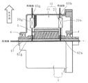
この発明による回転電機は、ハウジングと、上記ハウジングに回転可能に支持された回転軸に固着されて上記ハウジング内に配設された回転子と、スロットが径方向内方に開口して周方向に配列された円環状の電機子鉄心、およびそれぞれ、導体線を曲げ成形して作製され、上記電機子鉄心に装着された複数のコイルからなる電機子巻線を有し、上記回転子を囲繞するように上記回転子と同軸に配設されて上記ハウジングに保持された電機子と、を備え、上記回転軸の軸心を水平にして設置され、液冷媒を上記ハウジングに形成された冷媒吸入孔から上記電機子巻線のコイルエンドに吹き付けて、上記電機子巻線を冷却する。上記冷媒吸入孔は、上記ハウジングの上記コイルエンドの鉛直方向上方の位置に形成され、帯状の絶縁紙が、厚み方向を径方向として、上記導体線の上記コイルエンドを構成する部分の、径方向に隣接する導体部間に挿入されて、上記コイルエンド内に上記冷媒吸入孔の鉛直方向下方の位置を横切って周方向に延びるように配設されている。 A rotating electrical machine according to the present invention includes a housing, a rotor fixed to a rotating shaft rotatably supported by the housing and disposed in the housing, and a slot opening radially inward in the circumferential direction. An annular armature core arranged in an array, and an armature winding made of a plurality of coils mounted on the armature core, each of which is manufactured by bending a conductor wire, and surrounds the rotor And an armature disposed coaxially with the rotor and held by the housing, and installed in a state where the axis of the rotation shaft is horizontal, and a refrigerant suction hole formed in the housing for liquid refrigerant To the coil end of the armature winding to cool the armature winding. The refrigerant suction hole is formed at a position vertically above the coil end of the housing, and the strip-shaped insulating paper has a radial direction of a portion constituting the coil end of the conductor wire with a thickness direction as a radial direction. Is inserted between the conductor portions adjacent to each other, and is disposed in the coil end so as to extend in the circumferential direction across the position below the refrigerant suction hole in the vertical direction.
この発明によれば、帯状の絶縁紙が、厚み方向を径方向として、導体線のコイルエンドを構成する部分の、径方向に隣接する導体部間に挿入されて、コイルエンド内に冷媒吸入孔の鉛直方向下方の位置を横切って周方向に延びるように配設されている。そこで、コイルエンドに吹き付けられた液冷媒は、絶縁紙に当たり、コイルエンドの内径側への流出を抑えられて、コイルエンド内を周方向に流れる。これにより、液冷媒がコイルエンド内に周方向に万遍なく行き渡り、コイルエンドの冷却むらがなく、電機子巻線を効果的に冷却できる。また、コイルエンドの外径側に形成される冷媒吸入孔数が1つでよく、電機子巻線の冷却構造を簡素化できる。さらに、電機子巻線のコイルエンドの上部に絶縁ホルダを配設する必要がないので、回転電機の軸方向寸法の増大を抑えて、回転電機の小型化を図ることができる。 According to this invention, the strip-shaped insulating paper is inserted between the conductor portions adjacent to each other in the radial direction of the portion constituting the coil end of the conductor wire with the thickness direction as the radial direction, and the refrigerant suction hole is formed in the coil end. Are arranged so as to extend in the circumferential direction across a position below the vertical direction. Therefore, the liquid refrigerant sprayed on the coil end hits the insulating paper and is prevented from flowing out to the inner diameter side of the coil end and flows in the circumferential direction in the coil end. As a result, the liquid refrigerant spreads uniformly in the circumferential direction in the coil end, and there is no uneven cooling of the coil end, and the armature winding can be effectively cooled. Further, only one refrigerant suction hole is formed on the outer diameter side of the coil end, and the cooling structure of the armature winding can be simplified. Furthermore, since it is not necessary to provide an insulating holder above the coil end of the armature winding, an increase in the axial dimension of the rotating electrical machine can be suppressed, and the rotating electrical machine can be downsized.
以下、本発明による回転電機の好適な実施の形態につき図面を用いて説明する。 Hereinafter, preferred embodiments of a rotating electrical machine according to the present invention will be described with reference to the drawings.
実施の形態1.
図1はこの発明の実施の形態1に係る回転電機を示す片側断面図、図2はこの発明の実施の形態1に係る回転電機の要部を示す斜視図、図3はこの発明の実施の形態1に係る回転電機に適用される電機子を示す斜視図、図4はこの発明の実施の形態1に係る回転電機に適用される電機子鉄心を構成する鉄心ブロックを示す斜視図、図5はこの発明の実施の形態1に係る回転電機における電機子巻線を構成するコイルを示す斜視図、図6はこの発明の実施の形態1に係る回転電機における電機子巻線を構成するコイルを示す端面図、図7はこの発明の実施の形態1に係る回転電機における電機子巻線を構成するコイルを示す正面図、図8はこの発明の実施の形態1に係る回転電機に適用される電機子巻線を構成するコイルの配置を説明する断面模式図、図9はこの発明の実施の形態1に係る回転電機に適用される電機子巻線を示す斜視図である。なお、図8では、便宜上、第1から第3コイルエンド部を直線で示している。
Embodiment 1 FIG.
1 is a half sectional view showing a rotating electrical machine according to Embodiment 1 of the present invention, FIG. 2 is a perspective view showing a main part of the rotating electrical machine according to Embodiment 1 of the present invention, and FIG. 3 is an embodiment of the present invention. 4 is a perspective view showing an armature applied to the rotary electric machine according to Embodiment 1, FIG. 4 is a perspective view showing an iron core block constituting the armature core applied to the rotary electric machine according to Embodiment 1 of the present invention, and FIG. FIG. 6 is a perspective view showing a coil constituting the armature winding in the rotary electric machine according to Embodiment 1 of the present invention, and FIG. 6 shows the coil constituting the armature winding in the rotary electric machine according to Embodiment 1 of the present invention. FIG. 7 is a front view showing a coil constituting the armature winding in the rotary electric machine according to Embodiment 1 of the present invention, and FIG. 8 is applied to the rotary electric machine according to Embodiment 1 of the present invention. Section explaining the arrangement of the coils that make up the armature winding Wherein Figure 9 is a perspective view showing an armature winding that is applied to the rotary electric machine according to Embodiment 1 of the present invention. In FIG. 8, for convenience, the first to third coil end portions are shown by straight lines.
図1および図2において、回転電機100は、有底円筒状のフレーム2およびフレーム2の開口を塞口する端板3を有するハウジング1と、フレーム2の円筒部に内嵌状態に固着された電機子10と、フレーム2の底部および端板3にベアリング4を介して回転可能に支持された回転軸6に固着されて、電機子10の内周側に回転可能に配設された回転子5と、を備えている。
1 and 2, the rotating
液冷媒を供給するための冷媒吸入孔60a,60bが、電機子巻線20の電機子鉄心11の軸方向両端から軸方向外方に突出するコイルエンドのそれぞれの径方向外方に位置するようにフレーム2の円筒部に1つずつ形成されている。また、液冷媒が供給される中心孔61が、回転軸6の軸心位置を軸方向に貫通するように形成されている。さらに、中心孔61から径方向に分岐する噴射孔62a,62bが、電機子巻線20のコイルエンドのそれぞれの径方向内方に位置するように、回転軸6に形成されている。
回転子5は、軸心位置に挿通された回転軸6に固着された回転子鉄心7と、回転子鉄心7の外周面側に埋設されて周方向に一定の間隔で配列され、磁極を構成する永久磁石8と、を備えた永久磁石型回転子である。なお、回転子5は、永久磁石式回転子に限定されず、絶縁しない回転子導体を、回転子鉄心のスロットに収納して、両側を短絡環で短絡したかご形回転子や、絶縁した導体線を回転子鉄心のスロットに装着した巻線形回転子を用いてもよい。
The
つぎに、電機子10の構成について具体的に図3から図9を参照しつつ説明する。
Next, the configuration of the
電機子10は、図3に示されるように、電機子鉄心11と、電機子鉄心11に装着された電機子巻線20と、電機子鉄心11と電機子巻線20とを電気的に隔離するスロットセル14と、備えている。ここで、説明の便宜上、回転子5の極数を10、電機子鉄心11のスロット数を60、電機子巻線20を三相巻線とする。すなわち、スロット13は、毎極毎相当たり2個の割合で電機子鉄心11に形成されている。
As shown in FIG. 3, the
鉄心ブロック12は、円環状の電機子鉄心11を周方向に30等分割したもので、図4に示されるように、多数枚の電磁鋼板を積層一体化して作製され、断面円弧形のコアバック部12aと、コアバック部12aの内周壁面から径方向内方に突出する2本のティース12bと、を備えている。
The
電機子鉄心11は、ティース12bを径方向内方に向けて、コアバック部12aの周方向の側面同士を突き合わせて、30個の鉄心ブロック12を周方向に配列、一体化して、円環状に構成されている。コアバック部12aと周方向に隣り合う2本のティース12bとにより構成されるスロット13が、内周側に開口するように、周方向に等角ピッチで配列されている。なお、ティース12bは、周方向幅が径方向内方に向って漸次狭くなる先細り形状に形成されており、スロット13の断面は長方形となっている。
The
スロットセル14は、例えばポリイミドフィルムをメタ系アラミド繊維で挟み込んで作製された長方形のシートを曲げ成形してU字状に形成され、スロット13内に挿入され、電機子鉄心11と電機子巻線20を電気的に隔離する。
The
電機子巻線20は、複数のコイル21により構成される。コイル21は、例えば、エナメル樹脂で絶縁被覆された、且つ接続部のない連続した銅線やアルミニウム線などからなる直径dの円形断面の導体線19をδ字状のコイルパターンに巻回して作製される。なお、コイル21は、長方形断面の導体線19をδ字状のコイルパターンに巻回して作製してもよい。
The armature winding 20 is composed of a plurality of
コイル21は、図5から図7に示されるように、6スロット角度間隔離れて3列となった、第1、第2、第3および第4直線部21a,21b,21c,21dと、第1および第2直線部21a,21bの長さ方向の一端同士を連結する第1コイルエンド部21eと、第2および第3直線部21b,21cの長さ方向の他端同士を連結する第2コイルエンド部21fと、第3および第4直線部21c,21dの長さ方向の一端同士を連結する第3コイルエンド部21gと、第1直線部21aの長さ方向の他端から延びる第1コイル端末21hと、第4直線部21dの長さ方向の他端から延びる第2コイル端末21jと、を備える。第1および第2コイル端末21h,21jは、他のコイル21や給電部、中性点などに接続される。なお、6スロット角度間隔とは、周方向に連続する6つのティース12bの両側のスロット13のスロット中心間の間隔であり、1磁極ピッチに相当する。
As shown in FIGS. 5 to 7, the
具体的には、コイル21は、図8に示されるように、導体線19が電機子鉄心11の軸方向一端側から1番のスロット13内の第1層に挿入され、1番のスロット13から電機子鉄心11の軸方向他端側に延び出て、周方向一側に6スロット角度間隔離れた7番のスロット13内の第2層に挿入され、7番のスロット13から電機子鉄心11の軸方向一端側に延び出て、周方向一側に6スロット角度間隔離れた13番のスロット13内の第3層に挿入され、13番のスロット13から電機子鉄心11の軸方向他端側に延び出て、周方向他側に6スロット角度間隔離れた7番のスロット13内の第4層に挿入され、7番のスロット13から電機子鉄心11の軸方向一端側に延び出るδ字状のコイルパターンに作製される。このように作製されるコイル21は、分布巻きのコイルである。
Specifically, as shown in FIG. 8, in the
なお、図8中、スロット13内に収納される導体線の収納位置を、便宜的に、外径側から第1層、第2層、第3層、第4層とした。また、図8中、1,2・・13はスロット13に周方向の並び順にふったスロット番号である。
In FIG. 8, the storage position of the conductor wire stored in the
ここで、1番のスロット13内の第1層から電機子鉄心11の軸方向一端側に延び出た第1コイルエンド部21eは、径方向位置を維持して、一定の傾きで周方向一側かつ軸方向外方に延び、中央部(頂部)のクランク部で径方向内方にdだけ変位され、その後逆向きの傾きで、径方向位置を維持して、周方向一側かつ軸方向内方に延び、7番のスロット13内の第2層に入る。
Here, the first
7番のスロット13内の第2層から電機子鉄心11の軸方向他端側に延び出た第2コイルエンド部21fは、径方向位置を維持して、一定の傾きで周方向一側かつ軸方向外方に延び、中央部(頂部)のクランク部で径方向内方にdだけ変位され、その後逆向きの傾きで、径方向位置を維持して、周方向一側かつ軸方向内方に延び、13番のスロット13内の第3層に入る。
The second coil end portion 21f extending from the second layer in the
13番のスロット13内の第3層から電機子鉄心11の軸方向一端側に延び出た第3コイルエンド部21gは、径方向位置を維持して、一定の傾きで周方向他側かつ軸方向外方に延び、中央部(頂部)のクランク部で径方向内方にdだけ変位され、その後逆向きの傾きで、径方向位置を維持して、周方向他側かつ軸方向内方に延び、7番のスロット13内の第4層に入る。
The third
1番のスロット13内の第1層から電機子鉄心11の軸方向他端側に延び出た第1コイル端末21hは、径方向位置を維持して、一定の傾きで周方向他側かつ軸方向外方に延び、その後曲げられて径方向外方に延び出している。
7番のスロット13内の第4層から電機子鉄心11の軸方向他端側に延び出た第2コイル端末21jは、径方向位置を維持して、一定の傾きで周方向一側かつ軸方向外方に延び、その後曲げられて径方向外方に延び出している。
The
The
このように、第1から第3コイルエンド部21e,21f,21gは、一対の傾斜部21e’,21f’,21g’と、径方向に導体線の径方向幅dだけ径方向に変位するクランク部と、を有している。また、第1および第2コイル端末21h,21jは、傾斜部21h’,21j’を有している。第1から第4直線部21a,21b,21c,21dは、直径dの円形断面に形成されている。第1から第3コイルエンド部21e,21f,21gおよび第1および第2コイル端末21h,21jは、例えば、円形断面の導体線を平行な平板で径方向の両側から加圧して、径方向厚みをd’(但し、d’<d)、軸方向厚みをd”(但し、d”>d)とする扁平な断面に塑性変形されている。
As described above, the first to third
このように作製された60個のコイル21を1スロットピッチで周方向に円環状に配列し、図9に示される電機子巻線20が組み立てられる。この電機子巻線20の軸方向一端側には、第1コイルエンド部21eを周方向に1スロットピッチで配列して構成された第1コイルエンド部列と、第3コイルエンド部21gを周方向に1スロットピッチで配列して構成された第3コイルエンド部列とが、径方向に2層に並んで第1コイルエンド20aを構成する。また、この電機子巻線20の軸方向他端側には、第2コイルエンド部21fを周方向に1スロットピッチで配列して構成された第2コイルエンド部列が、第2コイルエンド20bを構成する。さらに、軸方向外方に延び出している第1コイル端末21hの端部が、第2コイルエンド20bの外径側に周方向に1スロットピッチで配列する。さらにまた、軸方向外方に延び出している第2コイル端末21jの端部が、第2コイルエンド20bの内径側に周方向に1スロットピッチで配列する。
The 60 coils 21 produced in this way are arranged in an annular shape in the circumferential direction at a 1-slot pitch, and the armature winding 20 shown in FIG. 9 is assembled. On one end side of the armature winding 20 in the axial direction, a first
つぎに、電機子10を組み立てる方法を図10から図16を参照しつつ説明する。図10はこの発明の実施の形態1に係る回転電機における電機子巻線への絶縁紙の装着方法を説明する斜視図、図11および図12はそれぞれこの発明の実施の形態1に係る回転電機における電機子巻線への絶縁紙の装着方法を説明する模式断面図、図13はこの発明の実施の形態1に係る回転電機における電機子巻線の絶縁紙装着状態を示す模式断面図、図14はこの発明の実施の形態1に係る回転電機における電機子巻線の第1コイルエンドの絶縁紙装着状態を径方向外方から見た要部拡大図、図15および図16はそれぞれこの発明の実施の形態1に係る回転電機における電機子の組立方法を説明する図である。なお、図15および図16では、便宜上、電機子巻線を第1から第4直線部のみで示している。
Next, a method for assembling the
まず、電機子巻線20においては、第1から第3コイルエンド部21e,21f,21gおよび第1および第2コイル端末21h,21jは、直径dの円形断面の導体線19が、径方向厚みをd’(但し、d’<d)、軸方向厚みをd”(但し、d”>d)とする扁平な断面に塑性変形されている。そこで、図11に示されるように、第1から第3コイルエンド部21e,21f,21g内には、それぞれ、隙間S(=d−d’)が形成されている。
First, in the armature winding 20, the first to third
そこで、図10および図11に示されるように、円環状に作製された第2絶縁紙152が第1コイルエンド20a側から電機子巻線20に装着され、円環状に作製された第1および第3絶縁紙151,153が第2コイルエンド20b側から電機子巻線20に装着される。そして、図12に示されるように、第1絶縁紙151は、第3直線部21cと第4直線部21dとの間を通って第1コイルエンド20a側に移動され、第1コイルエンド部21e内の隙間Sに挿入される。また、第2絶縁紙152は、第2直線部21bと第3直線部21cとの間を通って第2コイルエンド20b側に移動され、第2コイルエンド部21f内の隙間Sに挿入される。さらに、第3絶縁紙153は、第1直線部21aと第2直線部21bとの間を通って第1コイルエンド20a側に移動され、第3コイルエンド部21g内の隙間Sに挿入される。
Therefore, as shown in FIG. 10 and FIG. 11, the second insulating
ついで、図12および図13に示されるように、第1絶縁紙151および第3絶縁紙153が、第2コイルエンド20b側から、第2コイル端末21jと第2コイルエンド部21fとの間の隙間、および第1コイル端末21hと第2コイルエンド部21fとの間の隙間に挿入される。また、第2絶縁紙152が、第1コイルエンド20a側から、第1コイルエンド部21eと第3コイルエンド部21gとの間の隙間に挿入される。
Next, as shown in FIGS. 12 and 13, the first insulating
第1絶縁紙151は、長尺帯状体に成形された絶縁紙を丸めて円環状に構成されている。第2絶縁紙152は、長尺帯状体に成形された絶縁紙を丸めて円環状に構成されている。そして、円形の貫通穴152aが、それぞれ、第2絶縁紙152を厚さ方向に貫通して、周方向に複数形成されている。第3絶縁紙153は、長尺帯状体に成形された絶縁紙を丸めて円環状に構成されている。そして、円形の貫通穴153aが、それぞれ、第3絶縁紙153を厚さ方向に貫通して、周方向に複数形成されている。
The first insulating
そして、図13に示されるように、第1コイルエンド部21e内の隙間Sに挿入された状態での第1絶縁紙151の直径をΦx1、第2コイルエンド部21f内の隙間Sに挿入された状態での第2絶縁紙152の直径をΦx2、第3コイルエンド部21g内の隙間Sに挿入された状態での第3絶縁紙153の直径をΦx3とした時、Φx1<Φx2<Φx3となっている。また、第1から第3絶縁紙151,152,153は、例えば、ポリイミド、アラミド、ポリエチレンテレフタラート(PET)、ポリフェニレンサルファイド(PPS)などの絶縁材料で作製される。
Then, as shown in FIG. 13, the diameter of the first insulating
ここで、第1コイルエンド20aに着目すれば、図14に示されるように、第1コイルエンド部21eのスロット13の第1層から突出して頂部に至る傾斜部21e’と第1コイルエンド部21eのスロット13の第2層から突出して頂部に至る傾斜部21e’とが、傾きを逆方向として、周方向に1スロットピッチで配列されて、第1コイルエンド部列を構成している。そこで、第1コイルエンド部列を径方向外方から見ると、第1コイルエンド部列の径方向に隣接する傾斜部21e’間に隙間S’が形成されている。そして、第3絶縁紙153は、径方向外方から見て貫通穴153aが隙間S’に重なるように第1コイルエンド部列内に配設されている。なお、第1コイルエンド部列の径方向に隣接する傾斜部21e’が、導体線19の第1コイルエンド20aを構成する部分の、径方向に隣接する導体部に相当する。
Here, paying attention to the
また、図示していないが、第1コイルエンド部21eのスロット13の第2層から突出して頂部に至る傾斜部21e’と第3コイルエンド部21gのスロット13の第3層から突出して頂部に至る傾斜部21g’とが、傾きを逆方向として、周方向に1スロットピッチで配列されている。そこで、第1コイルエンド部列内から径方向内方を見ると、第1コイルエンド部列と第3コイルエンド部列の径方向に隣接する傾斜部21e’,21g’間に隙間S’が形成される。そして、第2絶縁紙152は、径方向外方から見て貫通穴152aが隙間S’に重なるように第1コイルエンド部列と第3コイルエンド部列の間に配設される。なお、第1コイルエンド部列と第3コイルエンド部列の径方向に隣接する傾斜部21e’,21g’が、導体線19の第1コイルエンド20aを構成する部分の、径方向に隣接する導体部に相当する。
Although not shown, the
また、図示していないが、第3コイルエンド部21gのスロット13の第3層から突出して頂部に至る傾斜部21g’と、第3コイルエンド部21gのスロット13の第4層から突出して頂部に至る傾斜部21g’とが、傾きを逆方向として、周方向に1スロットピッチで配列され、第3コイルエンド部列を構成している。そして、第1絶縁紙151は、第3コイルエンド部列の径方向に隣接する傾斜部21g’間に配設される。なお、第3コイルエンド部列の径方向に隣接する傾斜部21g’が、導体線19の第1コイルエンド20aを構成する部分の、径方向に隣接する導体部に相当する。
Although not shown, an
また、第2コイルエンド20bに着目すれば、第1コイル端末21hのスロット13の第1層から突出して端部に至る傾斜部21h’と第2コイルエンド部21fのスロット13の第2層から突出して頂部に至る傾斜部21f’とが、傾きを逆方向として、周方向に1スロットピッチで配列されている。そこで、径方向外方から見ると、第1コイル端末21hの列と第2コイルエンド部列の径方向に隣接する傾斜部21h’,21f’間に隙間S’が形成されている。そして、第3絶縁紙153は、径方向外方から見て貫通穴153aが隙間S’に重なるように第1コイル端末21hの列と第2コイルエンド部列との間に配設される。なお、第1コイル端末21hの列と第2コイルエンド部列の径方向に隣接する傾斜部21h’,21f’が、導体線19の第2コイルエンド20bを構成する部分の、径方向に隣接する導体部に相当する。
If attention is paid to the
また、第2コイルエンド部21fのスロット13の第2層から突出して頂部に至る傾斜部21f’と、第2コイルエンド部21fのスロット13の第3層から突出して頂部に至る傾斜部21f’とが、傾きを逆方向として、周方向に1スロットピッチで配列されて、第2コイルエンド部列を構成している。そこで、径方向外方から第2コイルエンド部列を見ると、第2コイルエンド部21fの径方向に隣接する傾斜部21f’間に隙間S’が形成される。そして、第2絶縁紙152は、径方向外方から見て貫通穴152aが隙間S’に重なるように第2コイルエンド部列内に配設される。なお、第2コイルエンド部21fの径方向に隣接する傾斜部21f’が、導体線19の第2コイルエンド20bを構成する部分の、径方向に隣接する導体部に相当する。
Further, an inclined portion 21f ′ protruding from the second layer of the
また、第2コイルエンド部21fのスロット13の第3層から突出して頂部に至る傾斜部21f’と、第2コイル端末21jのスロット13の第4層から突出して端部に至る傾斜部21j’とが、傾きを逆方向として、周方向に1スロットピッチで配列されている。そして、第1絶縁紙151は、第2コイルエンド部列と第2コイル端末21jの列の径方向に隣接する傾斜部21f’,21j’間に配設される。なお、第2コイルエンド部列と第2コイル端末21jの列の径方向に隣接する傾斜部21f’,21j’が、導体線19の第2コイルエンド20bを構成する部分の、径方向に隣接する導体部に相当する。
Further, an inclined portion 21f ′ protruding from the third layer of the
ついで、径方向に1列に配列した第1から第4直線部21a,21b,21c,21dの各列にスロットセル14を装着する。ついで、30個の鉄心ブロック12が、図15に示されるように、ティース12bを第1から第4直線部21a,21b,21c,21dの列間の径方向外方に位置させるように、電機子巻線20の外周側に略等角ピッチで配列される。
Next, the
ついで、30個の鉄心ブロック12を同時に径方向内方に移動させる。この鉄心ブロック12の径方向内方への移動により、ティース12bが第1から第4直線部21a,21b,21c,21dの列間に挿入される。そして、隣り合う鉄心ブロック12のコアバック部12aの周方向側面同士が当接し、鉄心ブロック12の径方向内方への移動が阻止される。
Next, the 30 iron core blocks 12 are simultaneously moved radially inward. The
これにより、図16に示されるように、鉄心ブロック12が、コアバック部12aの周方向側面同士を当接させて円環状に配列し、電機子鉄心11を構成する。また、第1から第4直線部21a,21b,21c,21dの各列がスロット13内に収納され、電機子巻線20が電機子鉄心11に装着される。ついで、第1コイル端末21hおよび第2コイル端末21jに所望の結線処理が施され、電機子10が得られる。
As a result, as shown in FIG. 16, the
つぎに、回転電機100の運転中における電機子巻線20の冷却について図17および図18を参照しつつ説明する。図17はこの発明の実施の形態1に係る回転電機における冷却動作時の液冷媒の流れを説明する片側断面図、図18はこの発明の実施の形態1に係る回転電機における冷却動作時の液冷媒の流れを説明する模式図である。なお、図17および図18中、矢印は液冷媒の流れを示している。
Next, cooling of the armature winding 20 during operation of the rotating
この電機子10を組み込んだ回転電機100は、図17に示されるように、回転軸6の軸心を水平とし、フレーム2に形成された冷媒吸入孔60a,60bが天方向を向くように配置される。そして、回転電機100の運転中に、ATFオイルなどの液冷媒がオイルポンプ(図示せず)により冷媒吸入孔60a,60bおよび中心孔61に圧送される。
As shown in FIG. 17, the rotating
冷媒吸入孔60a,60bは電機子巻線20の第1および第2コイルエンド20a,20bの径方向外側に位置しているので、液冷媒は、冷媒吸入孔60a,60bから第1および第2コイルエンド20a,20bに吹き付けられる。そして、第1および第2コイルエンド20a,20bに吹き付けられた液冷媒は、図18に示されるように、第3絶縁紙153に当たり、第3絶縁紙153に沿って周方向両側に流れる。そして、液冷媒の一部が、貫通穴153aを通って内径側に流れ込み、第2絶縁紙152に沿って周方向に流れる。そして、液冷媒の一部が、貫通穴152aを通って内径側に流れ込み、第1絶縁紙151に沿って周方向に流れる。このように、液冷媒は、第1および第2コイルエンド20a,20b内を、外径側から内径側に浸透しつつ、周方向に流れ、フレーム2内の鉛直下方に溜まる。なお、第1絶縁紙151には貫通穴が形成されていないでの、液冷媒は第1および第2コイルエンド20a,20bから内径側に流れ出ない。
Since the
また、中心孔61に圧送された液冷媒は、遠心力により、噴射孔62a,62bから噴射され、第1および第2コイルエンド20a,20bの内径側に吹き付けられる。第1および第2コイルエンド20a,20bの内径側に吹き付けられた液冷媒は、第1および第2コイルエンド20a,20bに沿って周方向に流れるとともに、重力により滴下し、フレーム2内の鉛直下方に溜まる。フレーム2内の鉛直下方に溜まった液冷媒はオイルポンプにより冷媒吸入孔60a,60bおよび中心孔61に圧送され、第1および第2コイルエンド20a,20bの冷却に供される。
Moreover, the liquid refrigerant pumped to the
この実施の形態1によれば、帯状の第1から第3絶縁紙151,152,153が、導体線19の第1および第2コイルエンド20a,20bを構成する部分の、径方向に隣り合う傾斜部21e’,21f’,21g’,21h’,21j’間に挿入されて周方向に配設されている。最内径に位置する第1絶縁紙151を除く第2および第3絶縁紙152,153には、貫通穴152a,153aが形成されている。冷媒吸入孔60a,60bが、第1および第2コイルエンド20a,20bのそれぞれの径方向外方に位置するようにフレーム2の円筒部に1つずつ形成されている。そして、回転電機100は、回転軸6の軸心を水平として、冷媒吸入孔60a,60bが天方向を向くように配設されている。
According to the first embodiment, the strip-shaped first to third insulating
そこで、冷媒吸入孔60a,60bから第1および第2コイルエンド20a,20bに吹き付けられた液冷媒は、貫通穴152a,153aにより第1および第2コイルエンド20a,20bの内径側に浸透しつつ、第1から第3絶縁紙151,152,153により周方向に流れる。これにより、液冷媒が第1および第2コイルエンド20a,20b内の径方向および周方向に満遍なく行き渡るので、第1および第2コイルエンド20a,20bの冷却むらの発生が抑えられ、電機子巻線20を効果的に冷却することができる。
Therefore, the liquid refrigerant blown from the
また、第1および第2コイルエンド20a,20bの径方向外方に形成される冷媒吸入孔60a,60bがそれぞれ1つで済み、電機子巻線20の冷却構造を簡略化できる。
Further, only one
また、貫通穴が最内径に位置する第1絶縁紙151に形成されていないので、液冷媒が第1および第2コイルエンド20a,20bから内径側に流れ出にくい。そこで、液冷媒が回転子5と電機子10との間の空隙に流入することに起因する損失の悪化を防ぐことができる。
Further, since the through hole is not formed in the first insulating
また、貫通穴152a,153aが、径方向外方から見て、導体線19の第1および第2コイルエンド20a,20bを構成する部分の、径方向に隣り合う傾斜部21e’,21f’,21g’,21h’間に形成される隙間S’と重なっているので、液冷媒が第1および第2コイルエンド20a,20b内を内径側に流れやすくなり、電機子巻線20の冷却性能を高めることができる。
The through holes 152a, 153a are
また、噴射孔62a,62bが、第1および第2コイルエンド20a,20bの径方向内方の位置で、回転軸6の軸心位置に形成された中心孔61から径方向に分岐して回転軸6の外周面に至るように形成されている。そこで、回転電機100の運転中に、液冷媒を中心孔61に供給すれば、液冷媒が噴射孔62a,62bから噴射して、第1および第2コイルエンド20a,20bに内径側から吹き付けられるので、電機子巻線20の冷却性能をさらに高めることができる。
Further, the injection holes 62a and 62b are branched radially from the
なお、上記実施の形態1では、帯状の絶縁紙が円環状に丸められて第1および第2コイルエンド内にその周方向の全域に行き渡るように装着されているが、絶縁紙はフレームの円筒部に形成された冷媒吸入孔の真下位置に位置していれば、第1および第2コイルエンド内の周方向の全域に行き渡る必要はなく、例えばC字状に丸められて第1および第2コイルエンド内に装着されてもよい。 In Embodiment 1 described above, the strip-shaped insulating paper is rounded into an annular shape and mounted in the first and second coil ends so as to spread over the entire circumferential direction. If it is located immediately below the refrigerant suction hole formed in the part, it is not necessary to spread over the entire circumferential direction in the first and second coil ends, and for example, the first and second are rounded into a C shape. It may be mounted in the coil end.
また、上記実施の形態1では、円形の貫通穴が第2および第3絶縁紙に形成されているが、第2および第3絶縁紙に形成される貫通穴の穴形状は円形に限定されず、液冷媒が第2および第3絶縁紙を通り抜ける穴形状であればよく、例えば四角形や楕円形の穴形状でもよい。 In Embodiment 1 described above, the circular through hole is formed in the second and third insulating papers, but the shape of the through hole formed in the second and third insulating papers is not limited to a circular shape. Any hole shape may be used as long as the liquid refrigerant passes through the second and third insulating papers. For example, the hole shape may be rectangular or elliptical.
また、上記実施の形態1では、第1絶縁紙として貫通穴が形成されていない絶縁紙を用いているが、貫通穴が形成されている絶縁紙を第1絶縁紙に用いてもよい。
また、上記実施の形態1では、第1から第3絶縁紙を第1および第2コイルエンドに配設しているが、第1および第2コイルエンドに径方向に配設される絶縁紙の層数は3層に限定されず、1層、又は2層でもよい。例えば、絶縁紙の層数が1層の場合、第1から第3絶縁紙のいずれか1つの絶縁紙を配設すればよい。また、絶縁紙の層数が2層の場合、第1から第3絶縁紙の中から選択された2つの絶縁紙を配設すればよい。
In Embodiment 1 described above, the insulating paper having no through hole is used as the first insulating paper. However, the insulating paper having the through hole may be used as the first insulating paper.
In the first embodiment, the first to third insulating papers are disposed in the first and second coil ends. However, the insulating paper disposed in the radial direction in the first and second coil ends is provided. The number of layers is not limited to three, and may be one or two. For example, when the number of insulating paper layers is one, any one of the first to third insulating papers may be provided. When the number of insulating paper layers is two, two insulating papers selected from the first to third insulating papers may be provided.
また、上記実施の形態1では、コイルが、導体線をδ字状のコイルパターンに1回巻き回して作製されているが、コイルは、導体線をδ字状のコイルパターンを2回以上巻き回して作製されたコイルでもよい。また、コイルが、導体線をδ字状のコイルパターンに1回巻き回して作製されているが、コイルは、導体線を螺旋状に巻き回して作製された、いわゆる亀甲形のコイルでもよく、2つの直線部をコイルエンド部で連結したU字状のコイルでもよい。 In the first embodiment, the coil is manufactured by winding the conductor wire around the δ-shaped coil pattern once. However, the coil is wound around the conductor wire twice or more by the δ-shaped coil pattern. A coil produced by turning may be used. The coil is made by winding the conductor wire around the δ-shaped coil pattern once, but the coil may be a so-called turtle-shaped coil made by winding the conductor wire in a spiral shape, A U-shaped coil in which two linear portions are connected by a coil end portion may be used.
また、上記実施の形態1では、コイルエンド部が、6スロット角度間隔離れたスロットに挿入されている直線部の端部同士を連結しているが、コイルエンド部により連結される2本の直線部が挿入されるスロット間の間隔は、6スロット角度間隔に限定されず、2スロット角度間隔以上離れていればよい。 In Embodiment 1 described above, the coil end portion connects the ends of the straight portions inserted in the slots separated by 6 slot angular intervals, but the two straight lines connected by the coil end portion The interval between the slots into which the parts are inserted is not limited to the 6-slot angle interval, but may be any distance between the two slots.
また、上記実施の形態1では、第1コイルエンド部列と第3コイルエンド部列が径方向に2層に配列されているが、第1コイルエンド部列と第3コイルエンド部列が軸方向に2層に配列されてもよい。つまり、第1コイルエンド部列が第3コイルエンド部列の外側に位置するように配列されてもよい。例えば、4本の直線部がスロット内に径方向に1列に並んで挿入されている場合、第1コイルエンド部が第1層と第4層に位置する直線部の端部同士を連結し、第3コイルエンド部が第2層と第3層に位置する直線部の端部同士を連結することで、第1コイルエンド部列と第3コイルエンド部列が軸方向に2層に配列される構成を実現できる。そして、絶縁紙は、第1コイルエンド部のスロットの第1層から突出する傾斜部と第3コイルエンド部のスロットの第2層から突出する傾斜部との間、第3コイルエンド部列のスロットの第2層と第3層から突出する傾斜部間、および第3コイルエンド部のスロットの第3層から突出する傾斜部と第1コイルエンド部のスロットの第4層から突出する傾斜部との間のそれぞれに挿入される。 In the first embodiment, the first coil end portion row and the third coil end portion row are arranged in two layers in the radial direction, but the first coil end portion row and the third coil end portion row are axial. It may be arranged in two layers in the direction. In other words, the first coil end part rows may be arranged so as to be located outside the third coil end part rows. For example, when four linear portions are inserted in the slot in a line in the radial direction, the first coil end portion connects the ends of the linear portions located in the first layer and the fourth layer. The first coil end part row and the third coil end row are arranged in two layers in the axial direction by connecting the end portions of the linear portions located in the second layer and the third layer. Can be realized. The insulating paper is formed between the inclined portion protruding from the first layer of the slot of the first coil end portion and the inclined portion protruding from the second layer of the slot of the third coil end portion. Between the second layer of the slot and the inclined portion protruding from the third layer, and the inclined portion protruding from the third layer of the slot of the third coil end portion and the inclined portion protruding from the fourth layer of the slot of the first coil end portion Inserted between each.
1 ハウジング、5 回転子、6 回転軸、10 電機子、11 電機子鉄心、13 スロット、19 導体線、20 電機子巻線、21 コイル、21e 第1コイルエンド部、21e’ 傾斜部(導体部)、21f 第2コイルエンド部、21f’ 傾斜部(導体部)、21g 第3コイルエンド部、21g’ 傾斜部(導体部)、21h 第1コイル端末、21h’ 傾斜部(導体部)、21j 第2コイル端末、21j’ 傾斜部(導体部)、60a,60b 冷媒吸入孔、61 中心孔、62a,62b 噴射孔、151 第1絶縁紙、152 第2絶縁紙、152a 貫通穴、153 第3絶縁紙、153a 貫通穴。 DESCRIPTION OF SYMBOLS 1 Housing, 5 Rotor, 6 Rotating shaft, 10 Armature, 11 Armature core, 13 Slot, 19 Conductor wire, 20 Armature winding, 21 Coil, 21e 1st coil end part, 21e 'Inclined part (conductor part) ), 21f second coil end portion, 21f ′ inclined portion (conductor portion), 21g third coil end portion, 21g ′ inclined portion (conductor portion), 21h first coil terminal, 21h ′ inclined portion (conductor portion), 21j 2nd coil terminal, 21j 'inclination part (conductor part), 60a, 60b Refrigerant suction hole, 61 center hole, 62a, 62b injection hole, 151 1st insulating paper, 152 2nd insulating paper, 152a through-hole, 153 3rd Insulating paper, 153a Through hole.
冷媒吸入孔60a,60bは電機子巻線20の第1および第2コイルエンド20a,20bの径方向外側に位置しているので、液冷媒は、冷媒吸入孔60a,60bから第1および第2コイルエンド20a,20bに吹き付けられる。そして、第1および第2コイルエンド20a,20bに吹き付けられた液冷媒は、図18に示されるように、第3絶縁紙153に当たり、第3絶縁紙153に沿って周方向両側に流れる。そして、液冷媒の一部が、貫通穴153aを通って内径側に流れ込み、第2絶縁紙152に沿って周方向に流れる。そして、液冷媒の一部が、貫通穴152aを通って内径側に流れ込み、第1絶縁紙151に沿って周方向に流れる。このように、液冷媒は、第1および第2コイルエンド20a,20b内を、外径側から内径側に浸透しつつ、周方向に流れ、フレーム2内の鉛直下方に溜まる。なお、第1絶縁紙151には貫通穴が形成されていないので、液冷媒は第1および第2コイルエンド20a,20bから内径側に流れ出ない。
Since the
Claims (5)
上記ハウジングに回転可能に支持された回転軸に固着されて上記ハウジング内に配設された回転子と、
スロットが径方向内方に開口して周方向に配列された円環状の電機子鉄心、およびそれぞれ、導体線を曲げ成形して作製され、上記電機子鉄心に装着された複数のコイルからなる電機子巻線を有し、上記回転子を囲繞するように上記回転子と同軸に配設されて上記ハウジングに保持された電機子と、を備え、
上記回転軸の軸心を水平にして設置され、液冷媒を上記ハウジングに形成された冷媒吸入孔から上記電機子巻線のコイルエンドに吹き付けて、上記電機子巻線を冷却する回転電機において、
上記冷媒吸入孔は、上記ハウジングの上記コイルエンドの鉛直方向上方の位置に形成され、
帯状の絶縁紙が、厚み方向を径方向として、上記導体線の上記コイルエンドを構成する部分の、径方向に隣接する導体部間に挿入されて、上記コイルエンド内に上記冷媒吸入孔の鉛直方向下方の位置を横切って周方向に延びるように配設されている回転電機。 A housing;
A rotor fixed in a rotating shaft rotatably supported by the housing and disposed in the housing;
An annular armature core in which slots are opened inward in the radial direction and arranged in the circumferential direction, and an electric machine comprising a plurality of coils that are each formed by bending a conductor wire and mounted on the armature core An armature that has a child winding and is disposed coaxially with the rotor so as to surround the rotor and held by the housing;
In a rotating electrical machine that is installed with the axis of the rotating shaft horizontal, sprays liquid refrigerant from a refrigerant suction hole formed in the housing to a coil end of the armature winding, and cools the armature winding.
The refrigerant suction hole is formed at a position vertically above the coil end of the housing,
A band-shaped insulating paper is inserted between the conductor portions adjacent to each other in the radial direction of the portion constituting the coil end of the conductor wire, with the thickness direction as the radial direction, and the vertical direction of the refrigerant suction hole in the coil end. The rotating electrical machine is arranged so as to extend in the circumferential direction across a position below the direction.
上記液冷媒を通過させる貫通穴が、上記径方向にm層配設された絶縁紙のそれぞれに形成されている請求項1記載の回転電機。 The insulating paper inserted between the conductor portions adjacent in the radial direction is arranged in m layers (where m is an integer of 1 or more) in the radial direction,
The rotating electrical machine according to claim 1, wherein a through hole through which the liquid refrigerant passes is formed in each of the insulating papers arranged in m layers in the radial direction.
上記液冷媒を通過させる貫通穴が、最内径に位置する上記絶縁紙を除く上記絶縁紙のそれぞれに形成されている請求項1記載の回転電機。 The insulating paper inserted between the conductor portions adjacent in the radial direction is arranged in m layers (where m is an integer of 2 or more) in the radial direction,
The rotating electrical machine according to claim 1, wherein a through hole through which the liquid refrigerant passes is formed in each of the insulating papers excluding the insulating paper located at the innermost diameter.
Priority Applications (3)
| Application Number | Priority Date | Filing Date | Title |
|---|---|---|---|
| JP2014173869A JP5847258B1 (en) | 2014-08-28 | 2014-08-28 | Rotating electric machine |
| US14/616,829 US10770943B2 (en) | 2014-08-28 | 2015-02-09 | Rotary electric machine |
| CN201510214492.9A CN106208468B (en) | 2014-08-28 | 2015-04-29 | Rotating electric machine |
Applications Claiming Priority (1)
| Application Number | Priority Date | Filing Date | Title |
|---|---|---|---|
| JP2014173869A JP5847258B1 (en) | 2014-08-28 | 2014-08-28 | Rotating electric machine |
Publications (2)
| Publication Number | Publication Date |
|---|---|
| JP5847258B1 JP5847258B1 (en) | 2016-01-20 |
| JP2016049007A true JP2016049007A (en) | 2016-04-07 |
Family
ID=55169232
Family Applications (1)
| Application Number | Title | Priority Date | Filing Date |
|---|---|---|---|
| JP2014173869A Active JP5847258B1 (en) | 2014-08-28 | 2014-08-28 | Rotating electric machine |
Country Status (3)
| Country | Link |
|---|---|
| US (1) | US10770943B2 (en) |
| JP (1) | JP5847258B1 (en) |
| CN (1) | CN106208468B (en) |
Families Citing this family (7)
| Publication number | Priority date | Publication date | Assignee | Title |
|---|---|---|---|---|
| JP6113247B1 (en) * | 2015-10-22 | 2017-04-12 | 三菱電機株式会社 | Rotating electric machine stator |
| DE102016216027A1 (en) * | 2016-08-25 | 2018-03-01 | Continental Automotive Gmbh | Squirrel cage rotor for an asynchronous machine |
| US10498197B2 (en) * | 2017-05-08 | 2019-12-03 | GM Global Technology Operations LLC | Vehicle propulsion system and electric motor for a vehicle propulsion system |
| FR3093388B1 (en) * | 2019-02-28 | 2021-03-12 | Nidec Psa Emotors | Rotating electric machine with improved stator cooling |
| JP6873219B1 (en) * | 2019-12-13 | 2021-05-19 | 三菱電機株式会社 | Rotating machine |
| WO2021186594A1 (en) * | 2020-03-17 | 2021-09-23 | 株式会社 東芝 | Stator for rotating electrical machine, and rotating electrical machine |
| AT524330B1 (en) * | 2020-11-27 | 2022-05-15 | Miba Emobility Gmbh | Machine component for an electrical machine |
Citations (4)
| Publication number | Priority date | Publication date | Assignee | Title |
|---|---|---|---|---|
| JP2001095205A (en) * | 1999-09-20 | 2001-04-06 | Hitachi Ltd | Electric motor |
| JP2006033915A (en) * | 2004-07-12 | 2006-02-02 | Nissan Motor Co Ltd | Motor cooling device |
| JP2011035992A (en) * | 2009-07-30 | 2011-02-17 | Hitachi Automotive Systems Ltd | Rotating electric machine |
| JP2014117034A (en) * | 2012-12-07 | 2014-06-26 | Toshiba Corp | Stator and rotating electric machine |
Family Cites Families (8)
| Publication number | Priority date | Publication date | Assignee | Title |
|---|---|---|---|---|
| JPS54136601A (en) * | 1978-04-15 | 1979-10-23 | Hitachi Ltd | Stator for rotating electric machine |
| JP4586542B2 (en) * | 2005-01-17 | 2010-11-24 | トヨタ自動車株式会社 | Rotating electric machine |
| JP4293237B2 (en) * | 2006-12-21 | 2009-07-08 | 株式会社豊田自動織機 | stator |
| JP5021443B2 (en) | 2007-12-14 | 2012-09-05 | 日立オートモティブシステムズ株式会社 | Rotating electric machine |
| JP5368866B2 (en) * | 2009-04-21 | 2013-12-18 | 株式会社日本自動車部品総合研究所 | Rotating electric machine |
| CN101752958B (en) * | 2010-01-18 | 2012-11-14 | 东元总合科技(杭州)有限公司 | Water-cooled motor and motor cooling method |
| US8269383B2 (en) * | 2010-06-08 | 2012-09-18 | Remy Technologies, Llc | Electric machine cooling system and method |
| JP5741555B2 (en) * | 2012-11-07 | 2015-07-01 | 株式会社豊田自動織機 | Interphase insulating sheet and electric compressor in rotating electric machine |
-
2014
- 2014-08-28 JP JP2014173869A patent/JP5847258B1/en active Active
-
2015
- 2015-02-09 US US14/616,829 patent/US10770943B2/en active Active
- 2015-04-29 CN CN201510214492.9A patent/CN106208468B/en not_active Expired - Fee Related
Patent Citations (4)
| Publication number | Priority date | Publication date | Assignee | Title |
|---|---|---|---|---|
| JP2001095205A (en) * | 1999-09-20 | 2001-04-06 | Hitachi Ltd | Electric motor |
| JP2006033915A (en) * | 2004-07-12 | 2006-02-02 | Nissan Motor Co Ltd | Motor cooling device |
| JP2011035992A (en) * | 2009-07-30 | 2011-02-17 | Hitachi Automotive Systems Ltd | Rotating electric machine |
| JP2014117034A (en) * | 2012-12-07 | 2014-06-26 | Toshiba Corp | Stator and rotating electric machine |
Also Published As
| Publication number | Publication date |
|---|---|
| US20160065035A1 (en) | 2016-03-03 |
| US10770943B2 (en) | 2020-09-08 |
| CN106208468A (en) | 2016-12-07 |
| CN106208468B (en) | 2019-01-01 |
| JP5847258B1 (en) | 2016-01-20 |
Similar Documents
| Publication | Publication Date | Title |
|---|---|---|
| JP5847258B1 (en) | Rotating electric machine | |
| US10291106B2 (en) | Stator, rotary electric machine provided with the stator and method of manufacturing the stator | |
| JP5942714B2 (en) | Rotating electric machine | |
| US8247934B2 (en) | Cooling structure for electric rotating machine | |
| US7812498B2 (en) | Stator of electric rotating machine and electric rotating machine | |
| CN106464086B (en) | Rotary motor | |
| JP5774082B2 (en) | Rotating electric machine | |
| WO2014034157A1 (en) | Rotary electric machine and manufacturing method therefor | |
| JP5314908B2 (en) | Rotating electric machine stator and rotating electric machine | |
| JP6461158B2 (en) | Rotating electric machine stator and rotating electric machine equipped with the same | |
| JPWO2014162626A1 (en) | Rotating electric machine stator | |
| KR102140101B1 (en) | Synchronous generators of gearless wind power plants, methods for manufacturing synchronous generators and use of coils | |
| JP5972387B2 (en) | Electric machine | |
| CN109075624A (en) | Common laminated parts for accommodating multiple conductor geometries in electric machines | |
| JP6021772B2 (en) | Rotating electric machine | |
| US20130062978A1 (en) | Electric rotating machine | |
| JP6138360B2 (en) | Rotating electric machine and manufacturing method thereof | |
| JP5924352B2 (en) | Rotating electric machine | |
| CN107078611A (en) | Rotor or stator with plug-in flat winding heads | |
| JP6076711B2 (en) | Squirrel-cage induction motor | |
| JP5330860B2 (en) | Rotating electric machine | |
| JP5901503B2 (en) | Rotating electric machine | |
| US11223247B2 (en) | Stator for rotary electric machine | |
| JP6801444B2 (en) | Stator | |
| JP2017070090A (en) | Rotating electric machine stator |
Legal Events
| Date | Code | Title | Description |
|---|---|---|---|
| TRDD | Decision of grant or rejection written | ||
| A01 | Written decision to grant a patent or to grant a registration (utility model) |
Free format text: JAPANESE INTERMEDIATE CODE: A01 Effective date: 20151027 |
|
| A61 | First payment of annual fees (during grant procedure) |
Free format text: JAPANESE INTERMEDIATE CODE: A61 Effective date: 20151124 |
|
| R150 | Certificate of patent or registration of utility model |
Ref document number: 5847258 Country of ref document: JP Free format text: JAPANESE INTERMEDIATE CODE: R150 |
|
| R250 | Receipt of annual fees |
Free format text: JAPANESE INTERMEDIATE CODE: R250 |
|
| R250 | Receipt of annual fees |
Free format text: JAPANESE INTERMEDIATE CODE: R250 |
|
| R250 | Receipt of annual fees |
Free format text: JAPANESE INTERMEDIATE CODE: R250 |
|
| R250 | Receipt of annual fees |
Free format text: JAPANESE INTERMEDIATE CODE: R250 |
|
| R250 | Receipt of annual fees |
Free format text: JAPANESE INTERMEDIATE CODE: R250 |
|
| R250 | Receipt of annual fees |
Free format text: JAPANESE INTERMEDIATE CODE: R250 |
|
| S111 | Request for change of ownership or part of ownership |
Free format text: JAPANESE INTERMEDIATE CODE: R313111 |
|
| R350 | Written notification of registration of transfer |
Free format text: JAPANESE INTERMEDIATE CODE: R350 |
|
| R250 | Receipt of annual fees |
Free format text: JAPANESE INTERMEDIATE CODE: R250 |