JP2016005004A - Transformer - Google Patents
Transformer Download PDFInfo
- Publication number
- JP2016005004A JP2016005004A JP2015122603A JP2015122603A JP2016005004A JP 2016005004 A JP2016005004 A JP 2016005004A JP 2015122603 A JP2015122603 A JP 2015122603A JP 2015122603 A JP2015122603 A JP 2015122603A JP 2016005004 A JP2016005004 A JP 2016005004A
- Authority
- JP
- Japan
- Prior art keywords
- winding
- foil
- strips
- transformer
- gap
- Prior art date
- Legal status (The legal status is an assumption and is not a legal conclusion. Google has not performed a legal analysis and makes no representation as to the accuracy of the status listed.)
- Granted
Links
Images




Classifications
-
- H—ELECTRICITY
- H01—ELECTRIC ELEMENTS
- H01F—MAGNETS; INDUCTANCES; TRANSFORMERS; SELECTION OF MATERIALS FOR THEIR MAGNETIC PROPERTIES
- H01F27/00—Details of transformers or inductances, in general
- H01F27/28—Coils; Windings; Conductive connections
- H01F27/2847—Sheets; Strips
- H01F27/2852—Construction of conductive connections, of leads
-
- H—ELECTRICITY
- H01—ELECTRIC ELEMENTS
- H01F—MAGNETS; INDUCTANCES; TRANSFORMERS; SELECTION OF MATERIALS FOR THEIR MAGNETIC PROPERTIES
- H01F27/00—Details of transformers or inductances, in general
- H01F27/24—Magnetic cores
-
- H—ELECTRICITY
- H01—ELECTRIC ELEMENTS
- H01F—MAGNETS; INDUCTANCES; TRANSFORMERS; SELECTION OF MATERIALS FOR THEIR MAGNETIC PROPERTIES
- H01F27/00—Details of transformers or inductances, in general
- H01F27/28—Coils; Windings; Conductive connections
- H01F27/30—Fastening or clamping coils, windings, or parts thereof together; Fastening or mounting coils or windings on core, casing, or other support
- H01F27/303—Clamping coils, windings or parts thereof together
-
- H—ELECTRICITY
- H01—ELECTRIC ELEMENTS
- H01F—MAGNETS; INDUCTANCES; TRANSFORMERS; SELECTION OF MATERIALS FOR THEIR MAGNETIC PROPERTIES
- H01F27/00—Details of transformers or inductances, in general
- H01F27/28—Coils; Windings; Conductive connections
- H01F27/30—Fastening or clamping coils, windings, or parts thereof together; Fastening or mounting coils or windings on core, casing, or other support
- H01F27/306—Fastening or mounting coils or windings on core, casing or other support
-
- H—ELECTRICITY
- H01—ELECTRIC ELEMENTS
- H01F—MAGNETS; INDUCTANCES; TRANSFORMERS; SELECTION OF MATERIALS FOR THEIR MAGNETIC PROPERTIES
- H01F27/00—Details of transformers or inductances, in general
- H01F27/34—Special means for preventing or reducing unwanted electric or magnetic effects, e.g. no-load losses, reactive currents, harmonics, oscillations, leakage fields
-
- H—ELECTRICITY
- H01—ELECTRIC ELEMENTS
- H01F—MAGNETS; INDUCTANCES; TRANSFORMERS; SELECTION OF MATERIALS FOR THEIR MAGNETIC PROPERTIES
- H01F27/00—Details of transformers or inductances, in general
- H01F27/28—Coils; Windings; Conductive connections
- H01F27/2847—Sheets; Strips
- H01F2027/2857—Coil formed from wound foil conductor
Landscapes
- Engineering & Computer Science (AREA)
- Power Engineering (AREA)
- Coils Of Transformers For General Uses (AREA)
- Coils Or Transformers For Communication (AREA)
Abstract
Description
発明は、一般的には変成器に関する。更に詳しくは、発明は、フォイル巻線を有する変成器であって、フォイル巻線はフォイル巻線の漏れインダクタンスを低減するために交互積層部を有する変成器に関する。 The invention relates generally to transformers. More particularly, the invention relates to a transformer having foil windings, the foil windings having alternating stacks to reduce the leakage inductance of the foil windings.
多くの用途において、変成器の巻線の漏れインダクタンスを最小にしたいという要望がある。例えば、フライバックトポロジーを有するスイッチング電源“SMPS”において、1次巻線の漏れインダクタンスによって、1次巻線を介してフライバック電源の変成器に充電された全てのエネルギーを、2次巻線を介して変成器から放出することができない。変成器の巻線の漏れインダクタンスを低減させる既知の方法は、各巻線が変成器の一つ以上の他の巻線の対応する巻線部と交互積層された巻線部を備える交互積層巻線を用いることである。交互巻線に関連する固有の課題は、巻線を構成するために巻線部を接続するように巻線部の間に電気的な接続部を配置する必要があることである。同一の巻線に属する二つの巻線部の間の電気的な接続部は、一つ以上の他の巻線の一つ以上の他の巻線部を渡る接続ブリッジを形成する必要があり、この場合、一つ以上の他の巻線部は、交互積層配置において、対象としている巻線の二つの巻線部の間に配置される。巻線部の間の上述した電気的な接続部のインダクタンスを、交互積層巻線によって提供される利点すなわち漏れインダクタンスの低減が弱くなること又は損なわれることを回避するために、できるだけ小さくする必要がある。 In many applications, there is a desire to minimize the leakage inductance of the transformer windings. For example, in a switching power supply “SMPS” having a flyback topology, all the energy charged to the transformer of the flyback power supply through the primary winding by the leakage inductance of the primary winding is transferred to the secondary winding. Cannot be discharged from the transformer. A known method for reducing the leakage inductance of a transformer winding is an alternating stacked winding, wherein each winding comprises a winding portion that is alternately stacked with a corresponding winding portion of one or more other windings of the transformer. Is to use. An inherent problem associated with alternating windings is that electrical connections must be placed between the windings to connect the windings to form the windings. The electrical connection between two windings belonging to the same winding must form a connection bridge across one or more other windings of one or more other windings; In this case, one or more other winding portions are arranged between two winding portions of the target winding in an alternate stacked arrangement. The inductance of the electrical connection mentioned above between the windings must be as small as possible to avoid the advantages provided by the alternating windings, i.e. the reduction in leakage inductance, being weakened or impaired. is there.
フォイル巻線は、フォイル巻線の種々の利点のために多くの種類及び用途の変成器において一般的である。例えば、表皮効果は、同一の断面領域を有する円形導線における場合のように、平坦で薄いフォイル導体において有効導電領域を大きく減少させない。交互積層巻線に関連する上述した課題は、変成器のフォイル巻線を交互積層巻線を形成するように構成した場合、すなわち、電気的な接続部のインダクタンスができるだけ小さくなるように各フォイル巻線の巻線部の間に電気的な接続部を配置する必要がある場合にも存在する。 Foil windings are common in many types and applications of transformers because of the various advantages of foil windings. For example, the skin effect does not significantly reduce the effective conductive area in a flat and thin foil conductor, as is the case with circular conductors having the same cross-sectional area. The above-mentioned problem related to the alternating laminated winding is that when the foil winding of the transformer is configured to form the alternating laminated winding, that is, each foil winding so that the inductance of the electrical connection is as small as possible. It also exists when it is necessary to place electrical connections between the wire windings.
以下、種々の発明の実施の形態の一部の態様の基本的な理解を提供するために簡単化した要約を提供する。要約は、発明の詳細な概説ではない。発明の主要な又は重要な要素を特定することも発明の範囲を詳しく説明することも意図しない。以下の要約は、発明の例示する及び限定されない実施の形態の更に詳細な説明の序章としての簡単化した形態における発明の一部の概念を単に提供する。 The following presents a simplified summary in order to provide a basic understanding of some aspects of the various inventive embodiments. The summary is not a detailed overview of the invention. It is not intended to identify key or critical elements of the invention or to delineate the scope of the invention. The following summary merely provides some concepts of the invention in simplified form as an introduction to the more detailed description of the exemplary and non-limiting embodiments of the invention.
発明によれば、例示する及び必須ではないスイッチング電源“SMPS”の変成器とすることができる新たな変成器を提供する。発明による変成器は、
第1のフォイル巻線の第1の巻線部を構成する二つ以上の第1のフォイル導体と、
第1のフォイル巻線と略同一の磁気軸を有する第2のフォイル巻線の一つ以上の第2の巻線部を構成する一つ以上の第2のフォイル導体と、
を備え、磁気軸は、第1のフォイル導体及び第2のフォイル導体の横方向に略平行である。
In accordance with the invention, a new transformer is provided which can be a transformer for the illustrated and non-essential switching power supply “SMPS”. The transformer according to the invention is
Two or more first foil conductors constituting the first winding portion of the first foil winding;
One or more second foil conductors constituting one or more second winding portions of a second foil winding having substantially the same magnetic axis as the first foil winding;
The magnetic axis is substantially parallel to the lateral direction of the first foil conductor and the second foil conductor.
第1の巻線部は、第1のフォイル巻線及び第2のフォイル巻線の漏れインダクタンスを低減するために磁気軸と略垂直な方向で第2の巻線部と交互積層される。 The first winding portion is alternately laminated with the second winding portion in a direction substantially perpendicular to the magnetic axis in order to reduce leakage inductance of the first foil winding and the second foil winding.
第1のフォイル導体の各々の少なくとも一つの端部が、磁気軸に略平行な互いに逆の方向に折り曲げられた二つの細長片を構成するように分けられ、
第1の巻線部の一方に属する細長片の端部を、第1の巻線部の間に配置された第2の巻線部の特定の巻線部を渡る接続ブリッジを構成するために第1の巻線部の他方に属する細長片の端部に接続するように、
第1の巻線部は、電気的に相互接続される。
At least one end of each of the first foil conductors is divided to form two strips folded in opposite directions substantially parallel to the magnetic axis;
In order to configure a connection bridge across the end of the elongated piece belonging to one of the first winding portions and a specific winding portion of the second winding portion disposed between the first winding portions. To connect to the end of the elongated piece belonging to the other of the first winding part,
The first winding portions are electrically interconnected.
発明の例示する及び限定されない実施の形態による変成器において、第2の巻線部の個数は少なくとも2個であり、
第2のフォイル導体の各々の少なくとも一つの端部が、磁気軸に略平行な互いに逆の方向に折り曲げられた二つの細長片を構成するように分けられ、
第2の巻線部の一方に属する細長片の端部を、第2の巻線部の間に配置された第1の巻線部の特定の巻線部を渡る接続ブリッジを構成するために第2の巻線部の他方に属する細長片の端部に接続するように、
第2の巻線部は、電気的に相互接続される。
In a transformer according to an exemplary and non-limiting embodiment of the invention, the number of second winding sections is at least two;
At least one end of each of the second foil conductors is divided to form two strips folded in opposite directions substantially parallel to the magnetic axis;
In order to configure a connection bridge across the end of the elongated piece belonging to one of the second winding portions and the specific winding portion of the first winding portion disposed between the second winding portions To connect to the end of the elongated piece belonging to the other of the second winding part,
The second winding portions are electrically interconnected.
上述した巻線部のフォイル導体が、上述した方法で巻線部の間に電気的な接続部を設けるために用いられるので、追加の導体をフォイル導体の端部に接続する必要がない。さらに、フォイル導体の相互接続された端部がそれぞれ互いに逆方向に折り曲げられた二つの細長片を構成するために分かれるので、二つの巻線部の間の電気的な接続部はそれぞれ、二つの接続ブリッジを備える。これによって、上述した電気的な接続部のインダクタンスを減少させる。その理由は、二つの接続ブリッジが略平行に接続されるからである。さらに、電気的な接続部を、フォイル導体を流れる電流の分布において更に対称となるように構成することができる。その理由は、電気的な接続部を、フォイル導体の長手方向の対称軸に対して対称にすることができるからである。 Since the foil conductor of the winding part described above is used to provide an electrical connection between the winding parts in the manner described above, there is no need to connect an additional conductor to the end of the foil conductor. Furthermore, since the interconnected ends of the foil conductors are separated to form two strips each folded in opposite directions, the electrical connections between the two windings are each two A connection bridge is provided. This reduces the inductance of the electrical connection described above. This is because the two connection bridges are connected substantially in parallel. Furthermore, the electrical connection can be configured to be more symmetrical in the distribution of current flowing through the foil conductor. The reason is that the electrical connection can be symmetric with respect to the longitudinal symmetry axis of the foil conductor.
発明の例示する及び限定されない実施の形態による変成器は、第1のフォイル巻線及び第2のフォイル巻線と略同一の磁気軸を有する少なくとも一つの第3のフォイル巻線を更に備える。第3のフォイル巻線は、第1の巻線部及び第2の巻線部と交互積層されるとともに上述した方法で電気的に相互接続される二つ以上の第3の巻線部を備えてもよい。 The transformer according to the illustrated and non-limiting embodiment of the invention further comprises at least one third foil winding having a magnetic axis substantially the same as the first foil winding and the second foil winding. The third foil winding includes two or more third winding portions that are alternately stacked with the first winding portion and the second winding portion and are electrically interconnected in the manner described above. May be.
発明の複数の例示する及び限定されない実施の形態を、伴う従属項に記載する。 Multiple exemplary and non-limiting embodiments of the invention are described in the accompanying dependent claims.
構成及び動作方法に関する発明の種々の例示する及び限定されない実施の形態は、他の目的及びその利点と共に、特定の例示する及び限定されない実施の形態の以下の説明を添付図面に関連して読むときに当該説明から最もよく理解される。 Various illustrative and non-limiting embodiments of the invention relating to construction and method of operation, as well as other objects and advantages thereof, will be read in conjunction with the accompanying drawings in the following description of specific exemplary and non-limiting embodiments. Are best understood from the description.
動詞「備える」及び「有する」は、列挙しない特徴の存在を除外せず、かつ、列挙しない特徴の存在を必要としない限定のない制限としてこの文書で用いる。伴う従属項に列挙した特徴は、明記されていない限り相互に自由に組み合わせ可能である。さらに、この文書の最初から最後までの“a”又は“an”すなわち単数形の使用が複数を除外しないことを理解されたい。 The verbs “comprising” and “having” are used in this document as non-limiting restrictions that do not exclude the presence of features that are not listed and do not require the presence of features that are not listed. The features listed in the accompanying dependent claims can be freely combined with one another unless otherwise specified. Further, it should be understood that the use of the “a” or “an” or singular from the beginning to the end of this document does not exclude a plurality.
発明の例示する及び限定されない実施の形態並びにその利点を、添付図面を参照しながら以下で更に詳細に説明する。 Illustrative and non-limiting embodiments of the invention and their advantages are described in more detail below with reference to the accompanying drawings.
図1aは、発明の例示する及び限定されない実施の形態による変成器の斜視図を示す。図1bは、変成器の側面図を示し、図1cは、変成器の上面図を示し、図1dは、図1cに示すA−A線に沿った断面図を示す。断面は、座標系199のxz面に平行である。変成器は、接続端子109及び110を介して外部電気システムに接続することができる第1のフォイル巻線と、接続端子111及び112を介して外部電気システムに接続することができる第2のフォイル巻線と、を備える。第1のフォイル巻線の磁気軸は、第2のフォイル巻線の磁気軸と略同一であり、座標系199のz軸に平行である。変成器を、例えば、スイッチング電源“SMPS”、例えば、フライバック電源又は共振コンバータの変成器とすることができるが、必ずしもそうする必要はない。第1のフォイル巻線は、1次巻線として動作してもよく、第2のフォイル巻線は、2次巻線として動作してもよい。
FIG. 1a shows a perspective view of a transformer according to an exemplary and non-limiting embodiment of the invention. 1b shows a side view of the transformer, FIG. 1c shows a top view of the transformer, and FIG. 1d shows a cross-sectional view along the line AA shown in FIG. 1c. The cross section is parallel to the xz plane of the coordinate
変成器の第1のフォイル巻線は、第1のフォイル導体の横方向が第1のフォイル巻線及び第2のフォイル巻線の磁気軸に平行になる、すなわち、座標系199のz軸に平行になるように第1のフォイル導体から構成した第1の巻線部によって構成される。第1の巻線部を図1c及び図1dに示し、これらに参照番号101及び102を付す。同様に、変成器の第2のフォイル巻線は、第2のフォイル導体の横方向が第1のフォイル巻線及び第2のフォイル巻線の磁気軸に平行になる、すなわち、座標系199のz軸に平行になるように第2のフォイル導体から構成した第2の巻線部によって構成される。第2の巻線部を図1c及び図1dに示し、これらに参照番号103及び104を付す。図1c及び図1dに示すように、巻線部101が最も奥の巻線となり、巻線部103が巻線部101と巻線部102との間にあり、巻線部104が最も外側の巻線となり、巻線部102が巻線部103と巻線部104との間となるように、巻線部101〜104は、座標軸199のz軸に垂直な方向で交互積層される。上述したような交互積層配置は一例にすぎず、多くの異なる交互積層配置が可能であることは注目すべきことである。例えば、フォイル巻線の一つ、例えば、第2のフォイル巻線を、対象としているフォイル巻線のみを構成するとともの他のフォイル巻線の巻線部の間に配置される一つの巻線部のみから構成することができる。他の例として、フォイル巻線の少なくとも一つは、他のフォイル巻線の巻線部と交互配置された三つ以上の巻線部を備えてもよい。
The first foil winding of the transformer is such that the transverse direction of the first foil conductor is parallel to the magnetic axis of the first foil winding and the second foil winding, ie, to the z-axis of the coordinate
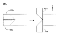
巻線部101のフォイル導体の端部は、座標系199のz軸に略平行な互いに逆の方向に折り曲げられた二つの細長片105a及び105bを構成するために分けられる。これを、細長片105a及び105bが折り曲げられた線を破線で示す図1eに示す。同様に、巻線部102のフォイル導体の端部は、z軸に略平行な互いに逆の方向に折り曲げられた二つの細長片106a及び106bを構成するために分けられ、巻線部103のフォイル導体の端部は、z軸に略平行な互いに逆の方向に折り曲げられた二つの細長片107a及び107bを構成するために分けられ、巻線部104のフォイル導体の端部は、z軸に略平行な互いに逆の方向に折り曲げられた二つの細長片108a及び108bを構成するために分けられる。
The ends of the foil conductors of the winding
細長片105a及び106aの端部は、図1dに示すように巻線部103を渡る接続ブリッジを構成するために相互接続される。細長片105a及び106aの端部を、例えば、はんだ付けによって又は機械的な締結手段、例えば、ボルト及びナットを用いることによって相互接続することができる。同様に、細長片105b及び106bの端部は、巻線部103を渡る他の接続ブリッジを構成するために相互接続される。細長片107a及び108aの端部は、図1dに示すように巻線部103を渡る接続ブリッジを構成するために相互接続される。同様に、細長片107b及び108bの端部は、巻線部103を渡る他の接続ブリッジを構成するために相互接続される。図1dに示すように、巻線部101及び102は、細長片105a及び106aの端部並びに細長片105b及び106bの端部によって構成される二つの接続ブリッジによって電気的に相互接続される。これによって、巻線部101と巻線部102との間の電気的な接続部のインダクタンスを低減する。その理由は、上述した二つの接続ブリッジが略平行に接続されるからである。さらに、二つの接続ブリッジによって形成された両側にある電気的な接続部は、巻線部101及び巻線部102のフォイル導体を流れる電流の分布を更に対称にする。上述したことは、巻線部103及び巻線部104にも当てはまる。
The ends of the
図1a〜図1eに示す例示する変成器は、第1のフォイル巻線及び第2のフォイル巻線によって包囲された脚部を有するコア構造113を備え、この場合、脚部の長手方向は、第1のフォイル巻線及び第2のフォイル巻線の磁気軸に略平行である、すなわち、座標軸199のz軸に平行である。図1a及び図1dにおいて、脚部に参照番号116を付す。図1aは、脚部116の一部を示し、図1dは、脚部の断面を示す。多くの用途において、コア構造113が強磁性材料を含むことが有利である。コア構造は、例えば、フェライト又は強磁性鋼板の束を服喪ことができる。しかしながら、上述した種類の交互積層されたフォイル巻線は、フェライトコア構造を備えない変成器においても適用可能である。
The exemplary transformer shown in FIGS. 1a-1e includes a
図2aは、発明の例示する及び限定されない実施の形態による変成器の断面図を示す。変成器は、接続端子209及び210を介して外部電気システムに接続することができる第1のフォイル巻線と、接続端子211及び212を介して外部電気システムに接続することができる第2のフォイル巻線と、を備える。第1のフォイル巻線及び第2のフォイル巻線は、座標系299のz軸に平行である略同一の磁気軸を有する。変成器の第1のフォイル巻線は、第1のフォイル導体の横方向が第1のフォイル巻線及び第2のフォイル巻線の磁気軸に平行になるように第1のフォイル導体から構成した第1の巻線部201及び第1の巻線部202によって構成される。変成器の第2のフォイル巻線は、第2のフォイル導体の横方向が第1のフォイル巻線及び第2のフォイル巻線の磁気軸に平行になるように第2のフォイル導体から構成した第2の巻線部203及び第2の巻線部204によって構成される。巻線部201が最も奥の巻線となり、巻線部203が巻線部201と巻線部202との間にあり、巻線部204が最も外側の巻線となり、巻線部202が巻線部203と巻線部204との間となるように、巻線部201〜204は、座標軸299のz軸に垂直な方向で交互積層される。変成器は、第1のフォイル巻線及び第2のフォイル巻線によって包囲された脚部216を有するコア構造213を備え、この場合、脚部の長手方向は、第1のフォイル巻線及び第2のフォイル巻線の磁気軸に略平行である、すなわち、座標軸299のz軸に平行である。脚部は、非強磁性ギャップによって脚部の長手方向において互いに離間した二つの部分216a及び部分216bを備える。図2bは、図2aの部分220の拡大を示す。図2bにおいて、非強磁性ギャップに参照番号217を付す。フォイル巻線のフォイル導体の各々は、磁気軸の方向において所定の距離だけ互いに離間した互いに平行な二つの細長片を備え、非強磁性ギャップ217によって生じた磁束219の広がりが脚部216に最も近接するフォイル導体に渦電流を誘導するのを妨げるために、細長片の間のギャップ218を非強磁性ギャップ217に合わせるようにする。図2a及び図2bにおいて、巻線部201のフォイル導体の二つの互いに平行な細長片に参照番号205a及び205bを付す。図2cは、図2aに示すように細長片の端部を対応する細長片206a及び細長片206bの端部に接続できるようにするために細長片の端部を二つの互いに逆の方向に折り曲げる方法を示す。
FIG. 2a shows a cross-sectional view of a transformer according to an exemplary and non-limiting embodiment of the invention. The transformer has a first foil winding that can be connected to the external electrical system via
磁気軸すなわちz軸の方向において所定の距離だけ互いに離間した二つの互いに平行な細長片を有するためにフォイル導体の一つの一部であるとともに脚部216に最も近接したフォイル導体部のみを配置して、これらの細長片の間のギャップを非強磁性ギャップ217に合わせることによっても上述したような渦電流の低減を行うことができることは、注目すべきことである。したがって、全てのフォイル導体が二つの互いに平行な細長片を構成する必要はなく、脚部に最も近接するフォイル導体全体が二つの互いに平行な細長片を構成する必要はない。異なる選択肢間の選択は、例えば、製造に関連した観点に依存する。
In order to have two parallel strips separated from each other by a predetermined distance in the direction of the magnetic axis or z-axis, only the foil conductor part that is part of one of the foil conductors and closest to the
図1a〜1e及び図2a〜2cに示す例示する変成器において、接続端子109〜112及び接続端子209〜212は、座標系199及び座標権299の正のz方向に突出するように片側にある。接続端子を、例えば、折り曲げ線が対象としているフォイル導体の長手方向に対して45°の角度を有するように略直角を形成するためにフォイル導体を折り曲げることによって構成することができる。場合に応じて図1eに示す方法又は図2cに示す方法で構成することができる両側の接続端子を有することもできる。
In the illustrated transformer shown in FIGS. 1 a-1 e and FIGS. 2 a-2 c, the connection terminals 109-112 and the connection terminals 209-212 are on one side so as to protrude in the positive z direction of the coordinate
図3は、発明の例示する及び限定されない実施の形態による変成器システムを示す。変成器システムは、変成器321と、第1の回路基板314と、第2の回路基板315と、を備える。回路基板は、座標系399のxy面に平行である。変成器を、例えば、図1a〜1eに示す変成器又は図2a〜2cに示す変成器とすることができる。この例示する場合において、変成器321の接続端子の各々は、回路基板314の導体にはんだ付けされる。座標系399の正のz方向に折り曲げられるとともに接続ブリッジの一つを構成する細長片の各対の端部は、回路基板314の導体にはんだ付けされ、座標系399の負のz方向に折り曲げられるとともに接続ブリッジの一つを構成する細長片の各対の端部は、回路基板315の導体にはんだ付けされる。接続端子及び/又は細長片の端部を、回路基板の貫通孔に通した後に回路基板の導体にはんだ付けすることができる。接続端子及び/又は細長片の端部を、回路基板の表面上の接続パッドにはんだ付けし又は他の方法で取り付けることもできる。
FIG. 3 shows a transformer system according to an exemplary and non-limiting embodiment of the invention. The transformer system includes a
上記説明で提供した特定の限定されない例は、添付した特許請求の範囲及び/又は添付した特許請求の範囲の適用性を制限するものと解釈すべきでない。例えば、発明の例示する及び限定されない実施の形態による変成器は、互いに交互積層された巻線部を有する三つ以上のフォイル巻線を備えてもよい。 The specific non-limiting examples provided in the above description should not be construed as limiting the scope of the appended claims and / or the applicability of the appended claims. For example, a transformer according to an exemplary and non-limiting embodiment of the invention may include three or more foil windings having winding portions that are alternately stacked on each other.
Claims (16)
前記第1のフォイル巻線と略同一の磁気軸を有する第2のフォイル巻線の一つ以上の第2の巻線部(103,104,203,204)を構成する一つ以上の第2のフォイル導体と、
を備え、前記磁気軸は、前記第1のフォイル導体及び前記第2のフォイル導体の横方向に略平行であり、前記第1の巻線部は、前記磁気軸と略垂直な方向で前記第2の巻線部と交互積層される変成器において、
前記第1のフォイル導体の各々の少なくとも一つの端部が、前記磁気軸に略平行な互いに逆の方向に折り曲げられた二つの細長片(105a,105b,106a,106b,205a,205b,206a,206b)を構成するように分けられ、
前記第1の巻線部の一方(101,201)に属する前記細長片(105a,105b,205a,205b)の端部を、前記第1の巻線部の間に配置された前記第2の巻線部の特定の巻線部(103,203)を渡る接続ブリッジを構成するために前記第1の巻線部の他方(102,202)に属する前記細長片(106a,106b,206a,206b)の端部に接続するように、
前記第1の巻線部は、電気的に相互接続されることを特徴とする変成器。 Two or more first foil conductors constituting the first winding portion (101, 102, 201, 202) of the first foil winding;
One or more second windings constituting one or more second winding portions (103, 104, 203, 204) of a second foil winding having substantially the same magnetic axis as the first foil winding. Foil conductor,
The magnetic axis is substantially parallel to a lateral direction of the first foil conductor and the second foil conductor, and the first winding portion is substantially perpendicular to the magnetic axis. In a transformer that is alternately stacked with two winding sections,
Two strips (105a, 105b, 106a, 106b, 205a, 205b, 206a, at least one end of each of the first foil conductors are bent in opposite directions substantially parallel to the magnetic axis. 206b),
An end of the elongated piece (105a, 105b, 205a, 205b) belonging to one of the first winding portions (101, 201) is disposed between the first winding portions. The strips (106a, 106b, 206a, 206b) belonging to the other (102, 202) of the first winding part in order to constitute a connection bridge across a specific winding part (103, 203) of the winding part. ) To connect to the end of
The transformer is characterized in that the first winding portion is electrically interconnected.
前記第2のフォイル導体の各々の少なくとも一つの端部が、前記磁気軸に略平行な互いに逆の方向に折り曲げられた二つの細長片(107a,107b,108a,108b)を構成するように分けられ、
前記第2の巻線部の一方(103)に属する前記細長片(107a,107b)の端部を、前記第2の巻線部の間に配置された前記第1の巻線部の特定の巻線部(102)を渡る接続ブリッジを構成するために前記第2の巻線部の他方(104)に属する前記細長片(108a,108b)の端部に接続するように、
前記第2の巻線部は、電気的に相互接続される請求項1に記載の変成器。 The number of the second winding parts is at least two,
At least one end of each of the second foil conductors is divided so as to constitute two elongated pieces (107a, 107b, 108a, 108b) bent in opposite directions substantially parallel to the magnetic axis. And
An end of the elongated piece (107a, 107b) belonging to one (103) of the second winding portion is connected to a specific portion of the first winding portion disposed between the second winding portions. So as to connect to the end of the strip (108a, 108b) belonging to the other (104) of the second winding to form a connecting bridge across the winding (102)
The transformer of claim 1, wherein the second winding portion is electrically interconnected.
Applications Claiming Priority (2)
| Application Number | Priority Date | Filing Date | Title |
|---|---|---|---|
| FI20145590 | 2014-06-19 | ||
| FI20145590A FI125524B (en) | 2014-06-19 | 2014-06-19 | Transformer |
Publications (3)
| Publication Number | Publication Date |
|---|---|
| JP2016005004A true JP2016005004A (en) | 2016-01-12 |
| JP2016005004A5 JP2016005004A5 (en) | 2016-05-12 |
| JP6352858B2 JP6352858B2 (en) | 2018-07-04 |
Family
ID=53385536
Family Applications (1)
| Application Number | Title | Priority Date | Filing Date |
|---|---|---|---|
| JP2015122603A Active JP6352858B2 (en) | 2014-06-19 | 2015-06-18 | Transformer |
Country Status (6)
| Country | Link |
|---|---|
| US (1) | US9472334B2 (en) |
| EP (1) | EP2958117B1 (en) |
| JP (1) | JP6352858B2 (en) |
| KR (1) | KR101797540B1 (en) |
| CN (1) | CN105321677B (en) |
| FI (1) | FI125524B (en) |
Cited By (2)
| Publication number | Priority date | Publication date | Assignee | Title |
|---|---|---|---|---|
| JP2018064009A (en) * | 2016-10-12 | 2018-04-19 | オムロン株式会社 | Transformer and power converter including the same |
| WO2019131883A1 (en) * | 2017-12-27 | 2019-07-04 | 株式会社ボルター | Welding transformer |
Families Citing this family (10)
| Publication number | Priority date | Publication date | Assignee | Title |
|---|---|---|---|---|
| JP6352791B2 (en) * | 2014-12-11 | 2018-07-04 | Ckd株式会社 | Coil sheet, coil, and method of manufacturing coil |
| CN115359999B (en) * | 2018-11-02 | 2026-04-10 | 台达电子企业管理(上海)有限公司 | Transformer module and power module |
| US12002615B2 (en) | 2018-11-02 | 2024-06-04 | Delta Electronics (Shanghai) Co., Ltd. | Magnetic element, manufacturing method of magnetic element, and power module |
| CN111145988B (en) | 2018-11-02 | 2021-12-07 | 台达电子企业管理(上海)有限公司 | Transformer module and power module |
| US11133750B2 (en) | 2018-11-02 | 2021-09-28 | Delta Electronics (Shanghai) Co., Ltd. | Power module |
| CN111145996A (en) | 2018-11-02 | 2020-05-12 | 台达电子企业管理(上海)有限公司 | Method for manufacturing magnetic element and magnetic element |
| EP3648128B1 (en) * | 2018-11-02 | 2024-01-03 | Delta Electronics (Shanghai) Co., Ltd. | Transformer module and power module |
| KR102222128B1 (en) * | 2019-07-29 | 2021-03-03 | 현대일렉트릭앤에너지시스템(주) | Transformer with reduced eddy current and Calculation method of eddy current |
| WO2023081309A1 (en) * | 2021-11-04 | 2023-05-11 | Resonant Link, Inc. | Conductive materials in alternating magnetic fields |
| CN115172020B (en) * | 2022-07-11 | 2025-06-20 | 西安交通大学 | An EMI filter based on a double-winding folded PCB structure |
Citations (10)
| Publication number | Priority date | Publication date | Assignee | Title |
|---|---|---|---|---|
| JPS454099Y1 (en) * | 1967-04-03 | 1970-02-25 | ||
| JPS5032730Y1 (en) * | 1970-11-18 | 1975-09-25 | ||
| JPS53162325U (en) * | 1977-05-27 | 1978-12-19 | ||
| JPS53162324U (en) * | 1977-05-27 | 1978-12-19 | ||
| JPS59168614A (en) * | 1983-03-15 | 1984-09-22 | Toshiba Corp | Foil wound transformer |
| JPH03208314A (en) * | 1990-01-10 | 1991-09-11 | Matsushita Electric Ind Co Ltd | Converter transformer |
| JPH0722523U (en) * | 1993-09-16 | 1995-04-21 | 日本電気精器株式会社 | Stationary inductor |
| JP2007035804A (en) * | 2005-07-25 | 2007-02-08 | Matsushita Electric Works Ltd | Power conversion transformer |
| JP2007531328A (en) * | 2004-03-29 | 2007-11-01 | ザ トラスティーズ オブ ダートマウス カレッジ | Low AC Resistance Foil Winding for Magnetic Coil on Gapped Core |
| JP2012023193A (en) * | 2010-07-14 | 2012-02-02 | Toshiba Lighting & Technology Corp | Electric device and electric equipment |
Family Cites Families (19)
| Publication number | Priority date | Publication date | Assignee | Title |
|---|---|---|---|---|
| US3448340A (en) * | 1965-06-29 | 1969-06-03 | Wagner Electric Corp | Transformer |
| US3911332A (en) | 1971-12-29 | 1975-10-07 | George M Kunkel | Wound transformers and machine for making the same |
| US3891955A (en) | 1974-05-07 | 1975-06-24 | Westinghouse Electric Corp | Electrical inductive apparatus |
| US3939449A (en) * | 1975-01-15 | 1976-02-17 | Westinghouse Electric Corporation | Insulated transformer windings |
| US4327311A (en) * | 1979-08-31 | 1982-04-27 | Frequency, Technology, Inc. | Inductor-capacitor impedance devices and method of making the same |
| US4300112A (en) * | 1980-05-19 | 1981-11-10 | General Electric Company | Circuit arrangement for controlling transformer current |
| US4403205A (en) * | 1980-05-19 | 1983-09-06 | General Electric Company | Circuit arrangement for controlling transformer current |
| JPS58128713A (en) * | 1982-01-27 | 1983-08-01 | Hitachi Ltd | Transformer for large current |
| JPS62274610A (en) * | 1986-05-23 | 1987-11-28 | Toshiba Corp | Foil wound transformer |
| JPH10335156A (en) | 1997-05-27 | 1998-12-18 | Fuji Electric Co Ltd | Mold transformer winding |
| JPH114581A (en) | 1997-06-10 | 1999-01-06 | Seiko Precision Kk | Power supply circuit |
| DE29806718U1 (en) * | 1998-04-06 | 1998-11-19 | Glibitski, Marks, Prof. Dr., 12353 Berlin | Construction of the transformer for high current and high frequencies |
| DE19954682C1 (en) * | 1999-11-13 | 2001-08-09 | Helmut Wollnitzke | High frequency transformer |
| DE10040415C1 (en) * | 2000-08-18 | 2002-01-10 | Robert Seuffer Gmbh & Co Kg | Inductive component for transformer or choke coil has cylindrical coil body formed from 2 spiral conductor bands |
| US6930582B2 (en) | 2000-11-07 | 2005-08-16 | Iota Engineering Co. | Self lead foil winding configuration for transformers and inductors |
| US6642830B1 (en) * | 2000-11-07 | 2003-11-04 | Iota Engineering Co. | Self lead foil winding configuration for transformers and inductors |
| CN101593606B (en) * | 2009-03-30 | 2012-02-22 | 浙江大学 | Full-integrated EMI filter based on flexible multi-layer tapes |
| CN102737823A (en) * | 2011-04-07 | 2012-10-17 | 国琏电子(上海)有限公司 | transformer |
| DE112012005124T5 (en) * | 2011-12-07 | 2014-10-16 | Nec Tokin Corporation | Coil, choke and method of forming a coil |
-
2014
- 2014-06-19 FI FI20145590A patent/FI125524B/en active IP Right Grant
-
2015
- 2015-06-10 EP EP15171379.9A patent/EP2958117B1/en active Active
- 2015-06-18 US US14/742,846 patent/US9472334B2/en active Active
- 2015-06-18 KR KR1020150086479A patent/KR101797540B1/en not_active Expired - Fee Related
- 2015-06-18 JP JP2015122603A patent/JP6352858B2/en active Active
- 2015-06-19 CN CN201510429859.9A patent/CN105321677B/en active Active
Patent Citations (10)
| Publication number | Priority date | Publication date | Assignee | Title |
|---|---|---|---|---|
| JPS454099Y1 (en) * | 1967-04-03 | 1970-02-25 | ||
| JPS5032730Y1 (en) * | 1970-11-18 | 1975-09-25 | ||
| JPS53162325U (en) * | 1977-05-27 | 1978-12-19 | ||
| JPS53162324U (en) * | 1977-05-27 | 1978-12-19 | ||
| JPS59168614A (en) * | 1983-03-15 | 1984-09-22 | Toshiba Corp | Foil wound transformer |
| JPH03208314A (en) * | 1990-01-10 | 1991-09-11 | Matsushita Electric Ind Co Ltd | Converter transformer |
| JPH0722523U (en) * | 1993-09-16 | 1995-04-21 | 日本電気精器株式会社 | Stationary inductor |
| JP2007531328A (en) * | 2004-03-29 | 2007-11-01 | ザ トラスティーズ オブ ダートマウス カレッジ | Low AC Resistance Foil Winding for Magnetic Coil on Gapped Core |
| JP2007035804A (en) * | 2005-07-25 | 2007-02-08 | Matsushita Electric Works Ltd | Power conversion transformer |
| JP2012023193A (en) * | 2010-07-14 | 2012-02-02 | Toshiba Lighting & Technology Corp | Electric device and electric equipment |
Cited By (4)
| Publication number | Priority date | Publication date | Assignee | Title |
|---|---|---|---|---|
| JP2018064009A (en) * | 2016-10-12 | 2018-04-19 | オムロン株式会社 | Transformer and power converter including the same |
| WO2018070198A1 (en) * | 2016-10-12 | 2018-04-19 | オムロン株式会社 | Transformer and power converter provided with same |
| WO2019131883A1 (en) * | 2017-12-27 | 2019-07-04 | 株式会社ボルター | Welding transformer |
| JP6542499B1 (en) * | 2017-12-27 | 2019-07-10 | 株式会社ボルター | Welding transformer |
Also Published As
| Publication number | Publication date |
|---|---|
| KR101797540B1 (en) | 2017-11-14 |
| FI125524B (en) | 2015-11-13 |
| KR20150146429A (en) | 2015-12-31 |
| EP2958117A1 (en) | 2015-12-23 |
| CN105321677A (en) | 2016-02-10 |
| JP6352858B2 (en) | 2018-07-04 |
| EP2958117B1 (en) | 2017-03-29 |
| CN105321677B (en) | 2017-08-29 |
| US20150371765A1 (en) | 2015-12-24 |
| FI20145590A7 (en) | 2015-11-13 |
| US9472334B2 (en) | 2016-10-18 |
Similar Documents
| Publication | Publication Date | Title |
|---|---|---|
| JP6352858B2 (en) | Transformer | |
| TWI389147B (en) | Conductive winding structure and magnetic device using same | |
| JP6333525B2 (en) | Linear electromagnetic device | |
| US9437361B2 (en) | Three-phase high frequency transformer | |
| KR20150002731A (en) | Three-phase choke | |
| WO2019013131A1 (en) | Planar transformer and dcdc converter | |
| CN113890361A (en) | Power supply module | |
| JP2014075535A (en) | Induction apparatus | |
| JP2011187600A (en) | Electromagnetic coil device and transformer | |
| US20180286564A1 (en) | Power converter module | |
| JP2015188033A (en) | Thin coil and transformer | |
| CN208315350U (en) | Continuous coil for inductive element, transformer and power supply | |
| JPWO2019131883A1 (en) | Welding transformer | |
| JP2010245294A (en) | Three-phase high frequency transformer | |
| WO2024176532A1 (en) | Inductor | |
| CN105593956B (en) | The construction and transformer of coupling coil | |
| JP2018067660A (en) | Transformer and electric power conversion system | |
| KR20200094423A (en) | Transformer | |
| JP7118294B2 (en) | Transformers and power converters | |
| US20250046506A1 (en) | Multi-phase transformer and llc resonant converter | |
| JP2019096725A (en) | High frequency transformer and high frequency coil | |
| JP2022077887A (en) | Transformer unit | |
| JP2014216366A (en) | Transformer | |
| JP5977926B2 (en) | Transformer | |
| JP2020092241A (en) | Electric circuit device |
Legal Events
| Date | Code | Title | Description |
|---|---|---|---|
| A521 | Request for written amendment filed |
Free format text: JAPANESE INTERMEDIATE CODE: A523 Effective date: 20160315 |
|
| A621 | Written request for application examination |
Free format text: JAPANESE INTERMEDIATE CODE: A621 Effective date: 20160315 |
|
| A977 | Report on retrieval |
Free format text: JAPANESE INTERMEDIATE CODE: A971007 Effective date: 20170315 |
|
| A131 | Notification of reasons for refusal |
Free format text: JAPANESE INTERMEDIATE CODE: A131 Effective date: 20170509 |
|
| A601 | Written request for extension of time |
Free format text: JAPANESE INTERMEDIATE CODE: A601 Effective date: 20170802 |
|
| A521 | Request for written amendment filed |
Free format text: JAPANESE INTERMEDIATE CODE: A523 Effective date: 20171102 |
|
| TRDD | Decision of grant or rejection written | ||
| A01 | Written decision to grant a patent or to grant a registration (utility model) |
Free format text: JAPANESE INTERMEDIATE CODE: A01 Effective date: 20180508 |
|
| A61 | First payment of annual fees (during grant procedure) |
Free format text: JAPANESE INTERMEDIATE CODE: A61 Effective date: 20180607 |
|
| R150 | Certificate of patent or registration of utility model |
Ref document number: 6352858 Country of ref document: JP Free format text: JAPANESE INTERMEDIATE CODE: R150 |
|
| S111 | Request for change of ownership or part of ownership |
Free format text: JAPANESE INTERMEDIATE CODE: R313113 |
|
| R350 | Written notification of registration of transfer |
Free format text: JAPANESE INTERMEDIATE CODE: R350 |
|
| R250 | Receipt of annual fees |
Free format text: JAPANESE INTERMEDIATE CODE: R250 |
|
| R250 | Receipt of annual fees |
Free format text: JAPANESE INTERMEDIATE CODE: R250 |
|
| R250 | Receipt of annual fees |
Free format text: JAPANESE INTERMEDIATE CODE: R250 |
|
| R250 | Receipt of annual fees |
Free format text: JAPANESE INTERMEDIATE CODE: R250 |
|
| R250 | Receipt of annual fees |
Free format text: JAPANESE INTERMEDIATE CODE: R250 |