JP2015132245A - Wind power generator - Google Patents
Wind power generator Download PDFInfo
- Publication number
- JP2015132245A JP2015132245A JP2014005372A JP2014005372A JP2015132245A JP 2015132245 A JP2015132245 A JP 2015132245A JP 2014005372 A JP2014005372 A JP 2014005372A JP 2014005372 A JP2014005372 A JP 2014005372A JP 2015132245 A JP2015132245 A JP 2015132245A
- Authority
- JP
- Japan
- Prior art keywords
- blade
- lightning
- receiving portion
- wind power
- lightning receiving
- Prior art date
- Legal status (The legal status is an assumption and is not a legal conclusion. Google has not performed a legal analysis and makes no representation as to the accuracy of the status listed.)
- Pending
Links
Images





Classifications
-
- F—MECHANICAL ENGINEERING; LIGHTING; HEATING; WEAPONS; BLASTING
- F03—MACHINES OR ENGINES FOR LIQUIDS; WIND, SPRING, OR WEIGHT MOTORS; PRODUCING MECHANICAL POWER OR A REACTIVE PROPULSIVE THRUST, NOT OTHERWISE PROVIDED FOR
- F03D—WIND MOTORS
- F03D80/00—Details, components or accessories not provided for in groups F03D1/00 - F03D17/00
- F03D80/30—Lightning protection
-
- F—MECHANICAL ENGINEERING; LIGHTING; HEATING; WEAPONS; BLASTING
- F05—INDEXING SCHEMES RELATING TO ENGINES OR PUMPS IN VARIOUS SUBCLASSES OF CLASSES F01-F04
- F05B—INDEXING SCHEME RELATING TO WIND, SPRING, WEIGHT, INERTIA OR LIKE MOTORS, TO MACHINES OR ENGINES FOR LIQUIDS COVERED BY SUBCLASSES F03B, F03D AND F03G
- F05B2240/00—Components
- F05B2240/20—Rotors
- F05B2240/30—Characteristics of rotor blades, i.e. of any element transforming dynamic fluid energy to or from rotational energy and being attached to a rotor
- F05B2240/307—Blade tip, e.g. winglets
-
- Y—GENERAL TAGGING OF NEW TECHNOLOGICAL DEVELOPMENTS; GENERAL TAGGING OF CROSS-SECTIONAL TECHNOLOGIES SPANNING OVER SEVERAL SECTIONS OF THE IPC; TECHNICAL SUBJECTS COVERED BY FORMER USPC CROSS-REFERENCE ART COLLECTIONS [XRACs] AND DIGESTS
- Y02—TECHNOLOGIES OR APPLICATIONS FOR MITIGATION OR ADAPTATION AGAINST CLIMATE CHANGE
- Y02E—REDUCTION OF GREENHOUSE GAS [GHG] EMISSIONS, RELATED TO ENERGY GENERATION, TRANSMISSION OR DISTRIBUTION
- Y02E10/00—Energy generation through renewable energy sources
- Y02E10/70—Wind energy
- Y02E10/72—Wind turbines with rotation axis in wind direction
Landscapes
- Engineering & Computer Science (AREA)
- Life Sciences & Earth Sciences (AREA)
- Sustainable Development (AREA)
- Sustainable Energy (AREA)
- Chemical & Material Sciences (AREA)
- Combustion & Propulsion (AREA)
- Mechanical Engineering (AREA)
- General Engineering & Computer Science (AREA)
- Wind Motors (AREA)
Abstract
Description
本発明は、風力発電装置に関する。 The present invention relates to a wind turbine generator.
安定したエネルギー資源の確保や地球温暖化防止といった観点から、風力発電の導入が進む一方で、技術面では、設計管理上の問題、トラブルへの対応やメンテナンス対応の問題、また、各々の地域における特異な気象条件に起因する諸問題により、設置場所によっては計画された発電量が得られないという問題が顕在化している。なかでも、風力発電施設の落雷による故障や事故は、発生頻度の最も高い要因としてあげられ、ブレードの損傷など、多くの被害事例が報告されている。 While wind power generation is being introduced from the viewpoint of securing stable energy resources and preventing global warming, on the technical side, design management problems, problems handling and maintenance problems, and in each region Due to various problems caused by unusual weather conditions, the problem that the planned amount of power generation cannot be obtained depending on the installation location has become apparent. Among them, breakdowns and accidents due to lightning strikes at wind power generation facilities are the most frequently occurring factors, and many damage cases such as blade damage have been reported.
落雷は、直撃雷と誘導雷に区分され、直撃雷はブレード、ナセルなどの破損や電子部品などの焼損を引き起こし、損傷部が飛散して家屋の窓を壊した事例もある。誘導雷は、主としてサージ電流による電子部品等の焼損を引き起こし、火災の原因となる。落雷による被害は、ブレードや制御装置の故障が多く、特にブレードの故障の大半が落雷によるものであり、ブレードに対する落雷対策が重要な課題となっている。 Lightning strikes are classified into direct lightning strikes and induced lightning strikes, and direct lightning strikes cause damage to blades, nacelles, etc. and burnout of electronic parts, and there are cases where damaged parts are scattered and windows of houses are broken. Induced lightning mainly causes burnout of electronic components and the like due to a surge current, and causes a fire. Damage caused by lightning strikes is often caused by failures of blades and control devices, and most of the failures of the blades are particularly caused by lightning strikes, and measures against lightning strikes on the blades are an important issue.
本技術分野の背景技術として、特開2008−115783号公報(特許文献1)がある。特許文献1には、非導電性板材で翼形状に構成された風車用ブレードであって、導電性材料からなり、前記非導電性板材の外表面に露出し、ブレード前後方向に沿って長く形成された受雷部と、一端が前記受雷部に電気的に接続し、ブレード内で根部方向に延設された導線とを備えた風車用ブレードが開示されている。
As a background art in this technical field, there is JP-A-2008-115783 (Patent Document 1).
上記風車用ブレードによれば、導電性材料からなる受雷部はブレード外板から露出しているため、受雷しやすく、ブレード前後方向に沿って(好ましくは外表面を一周して)長く形成されているので、本受雷部より先端側に落雷しブレード表面を流れる沿面電流を本受雷部により捉えることにより逃しにくい。本受雷部で捉えた雷電流はブレード内に設置された導線により根部方向に導出され、ハブ及びタワーの金属部分又は地面まで延設した導線を通して地面に放出することができ、従って、雷を捉え避雷する信頼性の高いブレードが構成されるという効果がある。 According to the windmill blade described above, the lightning-receiving portion made of a conductive material is exposed from the blade outer plate, so that it is easy to receive lightning and is formed long along the blade front-rear direction (preferably around the outer surface). Therefore, lightning strikes from the lightning receiving part to the tip side and it is difficult to escape by capturing the creeping current flowing on the blade surface by the lightning receiving part. The lightning current captured by this lightning receiving part is led out to the root direction by the conducting wire installed in the blade, and can be released to the ground through the metallic part of the hub and tower or the conducting wire extending to the ground, so lightning is It has the effect of constructing a highly reliable blade that catches lightning.
上記のように、風力発電装置においては、風力発電装置のなかで最も高い位置に来ることになる風車の翼すなわちブレードに雷が落ちる可能性が高く、風力発電装置の信頼性向上にはブレードに対する落雷対策が大きな課題となっている。また、近年では、ブレードの軽量化と強度を両立するため、一般的にGFRP(Glass−Fiber−Reinforced−Plastics)と呼ばれるガラス繊維強化プラスチックがブレードの材料として用いられている。GFRPは絶縁物であり、ブレードが落雷を受けた場合、落雷をアースに受け流すためには、別途の導電体をブレードに設ける必要がある。 As described above, in a wind turbine generator, there is a high possibility that lightning will fall on the blades or blades of the wind turbine that will be at the highest position among the wind turbine generators. Lightning strike countermeasures are a major issue. In recent years, glass fiber reinforced plastic called GFRP (Glass-Fiber-Reinforced-Plastics) has been used as a material for blades in order to achieve both weight reduction and strength of the blades. The GFRP is an insulator, and when the blade receives a lightning strike, it is necessary to provide a separate conductor on the blade in order to receive the lightning strike to the ground.
図7Aに一般的な風力発電装置の全体概要を示す。一般的な風力発電装置は発電機の支柱となるタワー4の上に発電機を内蔵したナセル2が設けられており、ナセル3の一端にはハブ2および複数の翼すなわち複数のブレード1からなるロータが設けられる。図7Aに示すようにブレード1は、雷からの保護の為の受雷部すなわちレセプタ5を先端部分に備えている。
FIG. 7A shows an overall outline of a general wind turbine generator. A general wind power generator is provided with a
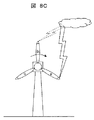
図7Bに落雷を受けた後のブレード1の先端部近傍の様子を示す。ブレード1の先端部近傍に備えられたレセプタ5はブレード1内に設けられた導電材10を介してアースに接続されている。本願発明者が落雷を受けた風車の事例を検討したところ、図7Bに示すように、ブレード1において、レセプタ5は落雷を受けた後でもダメージを受けていないのに対し、ブレード1の回転方向の後ろ側つまりレセプタ5よりもブレード1の後縁側に割れやひび等のダメージ部11が多く生じることが分かった。図8Aから図8Dに、図7Bにおけるダメージ部11の生じるメカニズムを示す。図8Aのように、落雷の開始時においては、風力発電装置の最も高い位置となるブレードa1aに落雷しやすい。ブレード1は風力発電装置の運転時には風を受けて回転しており、ブレード1の先端ほど速度が速く、その速度は70m/sec以上にもなる場合がある。従って、ブレードa1aに落雷した雷は、図8bに示すように、ブレードa1aの回転方向とは逆側つまりブレードa1aの後縁側に雷電流が引きずられる現象が発生する。この現象は、落雷の継続時間や電力値にもよるが、図8Cに示すように、ブレード1の回転により、ブレードb1bが最も高い位置に来て、ブレードb1bに落雷が遷移するまで続くような場合もあると推測される。
FIG. 7B shows a state near the tip of the
上記のようなメカニズムにより、図8Dに示すように、先端付近にレセプタ5を設けたブレード1の回転方向の後ろ側すなわち後縁側に雷電流が引きずられて、ブレード1にダメージ部11を発生させていると考えられる。ここで、ブレード1におけるレセプタ5の面積を大きくすることも可能であるが、必要以上にレセプタ5を大きくすると、ブレード1の重量が増加し、ブレード1の耐久性等に影響が生じる。つまり、図8Dにおけるダメージ部11の発生を防止するためにレセプタ5を大きくすると、ブレード1の先端重量が増し、その重力成分や慣性力成分がブレード荷重の増大を引き起こしてしまう。
Due to the mechanism as described above, as shown in FIG. 8D, the lightning current is dragged to the rear side in the rotation direction of the
特許文献1の風車用ブレードでは、上記のようなブレードの先端部に設けた受雷部よりも後縁側に対する落雷の影響を軽減するには不十分である。また、ブレードの前後方向に沿って(好ましくは外表面を一周して)長く形成されるため、必要以上にブレードの重量が増加してしまうデメリットがある。
The blade for wind turbines of
本発明の目的は、風力発電装置において、落雷によるブレードへの影響を最小限に抑え、信頼性の高い風力発電装置を提供することにある。 An object of the present invention is to provide a wind power generator with high reliability by minimizing the influence of lightning on the blades.
本発明は、地上または洋上に設置され、発電機の支柱となるタワーと、前記タワー上に設けられ、前記発電機を内蔵するナセルと、前記ナセルの一端に設けられ、風を受けて回転エネルギーへ変換するハブおよびブレードからなるロータと、を有する風力発電装置であって、前記ブレードの先端部近傍に設けられ、落雷時に落雷を受容する受雷部と、前記ブレードの後縁側表面に設けられ、前記受雷部と電気的に接続された金属箔と、を備えることを特徴とする。 The present invention is a tower installed on the ground or the ocean and serving as a prop of a generator, a nacelle provided on the tower and including the generator, provided at one end of the nacelle, receiving wind and rotating energy A wind turbine generator having a hub and a blade that converts to a blade, and provided near the tip of the blade and receiving a lightning strike during a lightning strike, and provided on a surface of the trailing edge of the blade And a metal foil electrically connected to the lightning receiver.
また、本発明は、地上または洋上に設置され、発電機の支柱となるタワーと、
前記タワー上に設けられ、前記発電機を内蔵するナセルと、前記ナセルの一端に設けられ、風を受けて回転エネルギーへ変換するハブおよびブレードからなるロータと、を有する風力発電装置であって、前記ブレードの先端部近傍に設けられ、落雷時に落雷を受容する第一の受雷部と、前記ブレードの後縁側表面に設けられ、前記第一の受雷部と電気的に接続された第二の受雷部と、を備えることを特徴とする。
Further, the present invention is a tower that is installed on the ground or offshore and serves as a prop of a generator,
A wind power generator having a nacelle provided on the tower and incorporating the generator, and a rotor comprising a hub and blades provided at one end of the nacelle for receiving wind and converting into rotational energy, A first lightning receiving portion provided near the tip of the blade and receiving a lightning strike during a lightning strike, and a second light receiving portion provided on the rear edge side surface of the blade and electrically connected to the first lightning receiving portion. And a lightning receiving portion.
また、本発明は、地上または洋上に設置され、発電機の支柱となるタワーと、前記タワー上に設けられ、前記発電機を内蔵するナセルと、前記ナセルの一端に設けられ、風を受けて回転エネルギーへ変換するハブおよびブレードからなるロータと、を有する風力発電装置であって、前記ブレードの先端部近傍に設けられ、落雷時に落雷を受容する受雷部と、を備え、前記受雷部は、前記ブレードの後縁側表面において、前記ブレードの後縁に沿って、前記ブレードの前記ハブ方向に延在するように設けられ、かつ、前記ブレードの前縁側表面において、前記ブレードの前縁に沿って、前記ブレードの前記ハブ方向に延在するように設けられ、前記ブレードの後縁側表面における前記受雷部の端部は、前記ブレードの前縁側表面における前記受雷部の端部よりも前記ハブ方向に長く設けられていることを特徴とする。 Further, the present invention provides a tower that is installed on the ground or the ocean and serves as a prop of a generator, a nacelle that is provided on the tower and that houses the generator, is provided at one end of the nacelle, and receives wind. A wind turbine generator having a hub and a blade that converts to rotational energy, and a lightning receiving portion that is provided near a tip of the blade and that receives a lightning strike during a lightning strike, the lightning receiving portion Is provided on the trailing edge surface of the blade so as to extend in the hub direction of the blade along the trailing edge of the blade, and on the leading edge of the blade on the leading edge surface of the blade. The end of the lightning receiving portion on the rear edge side surface of the blade is provided so as to extend in the hub direction of the blade. Characterized in that long provided in the hub direction than the end parts.
本発明によれば、風力発電装置において、落雷によるブレードへの影響を最小限に抑え、信頼性の高い風力発電装置を実現することができる。 According to the present invention, in a wind power generator, it is possible to minimize the influence of lightning on the blade and realize a highly reliable wind power generator.
上記した以外の課題、構成及び効果は、以下の実施形態の説明により明らかにされる。 Problems, configurations, and effects other than those described above will be clarified by the following description of embodiments.
以下、図面を用いて本発明の実施例を説明する。 Embodiments of the present invention will be described below with reference to the drawings.
図1に本発明の一実施例である風力発電装置におけるブレードの先端部近傍を示す。実施例1における風力発電装置の全体構成については、上記の図7Aで説明した代表的な風力発電装置と共通する部分について、その詳細な説明を省略して説明する。実施例1における風力発電装置のブレード1は、GFRPと呼ばれるガラス繊維強化プラスチックなどの絶縁材料により形成されている。ブレード1の先端部近傍には、落雷時に落雷を受容する受雷部すなわちレセプタ5が設けられている。
FIG. 1 shows the vicinity of the tip of a blade in a wind turbine generator according to an embodiment of the present invention. About the whole structure of the wind power generator in Example 1, the detailed description is abbreviate | omitted about the part which is common in the typical wind power generator demonstrated in said FIG. 7A. The
レセプタ5は、腐食に強く導電率が高い、アルミニウム(Al)材やステンレス鋼(SUS)材などの導電材料から形成されている。また、ブレード1の表面において、レセプタ5が設けられている位置よりもブレード1の回転方向の後ろ側すなわちブレード1の後縁14側の表面には、導電材8がレセプタ5と電気的に接続するように設けられている。また、導電材8は、ブレード1の後縁に沿って、レセプタ5からブレード1のハブ2方向に延在するように設けられている。導電材8は、ブレード1の重量を必要以上に増やさないよう、アルミニウム(Al)箔や薄く加工したステンレス鋼(SUS)材などの金属箔を用いるのが望ましい。導電材8として、例えば、裏面に導電性の接着材を塗布した金属箔などからなる金属テープを用いることにより、ブレード1の重量を必要以上に増やすことなく、容易な施工で、効果的にブレード1の後縁側表面の落雷対策を行うことができる。図1に波線を用いて示すようにブレード1の内部には、ブレード1の骨格となる構造材6が配置され、レセプタ5に落雷した雷電流をアースに逃がすための導電材となるケーブル7が設けられている。ここで構造材6は2列に図示されているが、列数は任意であり、また先端部においては存在しない場合もある。
The
ここで、ブレード1の後縁14に沿って、レセプタ5からブレード1のハブ2方向に延在するように設けられる導電材8の長さは、風力発電装置の規模やブレード形状(翼形状)にもよるが、30cmから100cm程度の長さで設けることにより、より効果的にブレード1の後縁14側に対する落雷を受容することができる。
Here, the length of the
以上説明したように、実施例1の風力発電装置によれば、必要以上にブレードの重量を増やすことなく、容易な施工で、落雷時の落雷をより効果的に受容し、落雷つまり雷電流をアースへ放電することができ、ブレード1に対するダメージを最小限に抑えることができる。これにより、落雷による故障や事故が少なく、信頼性の高い風力発電装置を実現することが可能となる。
As described above, according to the wind turbine generator of the first embodiment, lightning strikes can be received more effectively and lightning strikes, that is, lightning currents can be received more easily and easily without increasing the weight of the blades more than necessary. It is possible to discharge to the ground, and damage to the
図2に本発明の他の実施例である風力発電装置におけるブレードの先端部近傍を示す。実施例2における風力発電装置の全体構成については、実施例1で説明した部分と共通する部分について、その詳細な説明を省略して説明する。 FIG. 2 shows the vicinity of the tip of a blade in a wind turbine generator according to another embodiment of the present invention. About the whole structure of the wind power generator in Example 2, about the part which is common in the part demonstrated in Example 1, the detailed description is abbreviate | omitted and demonstrated.
実施例2における風力発電装置のブレード1は、図2の波線で示したブレード1の内部において、実施例1と同様にブレード1の骨格となる構造材6が配置され、レセプタ5に落雷した雷電流をアースに逃がすための導電材となるケーブル7が設けられている。実施例2では、ブレード1の先端部に設けられたレセプタ5の他に、ブレード1の先端部から離間した位置にレセプタ5とは別個に設けられた別の受雷部となる中間受雷部すなわち中間レセプタ9を備えている。
In the
中間レセプタ9はブレード1の内部において、導電材を介してケーブル7に接続される。レセプタ5からブレード1の後縁14側表面に沿って、ブレード1のハブ2方向へ延在するように導電材8が設けられている点では、実施例1と同様だが、実施例2では、導電材8はブレード1の表面において、レセプタ5と中間レセプタ9とを繋ぐように設けられている点で実施例1と異なっている。つまり、レセプタ5と中間レセプタ9は、ブレード1の内部でケーブル7を介して電気的に接続されているのに加え、ブレード1の表面において、導電材8により電気的に接続されている。実施例2のように、2つのレセプタ間すなわちレセプタ5と中間レセプタ9とを繋ぐようにブレード1の後縁14側表面にアルミニウム(Al)箔や薄く加工したステンレス鋼(SUS)材などの金属箔あるいは金属テープすなわち導電材8を張り付けることにより、より確実に導電経路を確保することができる。
The
ここで、実施例1と同様に、ブレード1の後縁14に沿って、レセプタ5からブレード1のハブ2方向に延在するように設けられる導電材8の長さは、風力発電装置の規模やブレード形状(翼形状)にもよるが、30cmから100cm程度の長さで設けることにより、より効果的にブレード1の後縁14側に対する落雷を受容することができる。
Here, as in the first embodiment, the length of the
実施例2の風力発電装置によれば、実施例1と同様に、必要以上にブレードの重量を増やすことなく、容易な施工で、落雷時の落雷をより効果的に受容し、落雷つまり雷電流をアースへ放電することができ、ブレード1に対するダメージを最小限に抑えることができる。これにより、落雷による故障や事故が少なく、信頼性の高い風力発電装置を実現することが可能となる。
According to the wind turbine generator of the second embodiment, as in the first embodiment, the lightning strike during the lightning strike can be received more effectively and easily by the construction without increasing the weight of the blade more than necessary. Can be discharged to ground, and damage to the
図3に本発明の別の実施例である風力発電装置におけるブレードの先端部近傍を示す。実施例3における風力発電装置の全体構成については、実施例1あるいは実施例2で説明した部分と共通する部分について、その詳細な説明を省略して説明する。 FIG. 3 shows the vicinity of the tip of a blade in a wind turbine generator according to another embodiment of the present invention. About the whole structure of the wind power generator in Example 3, about the part which is common in the part demonstrated in Example 1 or Example 2, the detailed description is abbreviate | omitted and demonstrated.
実施例3における風力発電装置のブレード1は、図3の波線で示したブレード1の内部においては、実施例1と同様にブレード1の骨格となる構造材6が配置され、レセプタ5に落雷した雷電流をアースに逃がすための導電材となるケーブル7が設けられている点で実施例1および実施例2と同様である。また、ブレード1の先端部に設けられたレセプタ5の他に、ブレード1の先端部から離間した位置にレセプタ5とは別個に設けられた別の受雷部となる中間受雷部すなわち中間レセプタ9を備えている点においても、実施例2と同様の構成となっている。
In the
ここで、実施例2では、導電材8すなわち金属箔あるいは金属テープが、ブレード1の表面において、レセプタ5と中間レセプタ9を繋ぐように設けられているのに対し、実施例3では、導電材8すなわち金属箔あるいは金属テープはブレード1の後縁にその端部を有し、レセプタ5と離間して形成されている。実施例3では、ブレード1のレセプタ5よりも後縁側において、導電材8すなわち金属箔あるいは金属テープとレセプタ5の間に、導電材8すなわち金属箔あるいは金属テープ形成されていない領域が存在するが、ブレード1の回転移動に伴いブレード1の後縁側に流れる落雷はブレード1の後縁に端部を有する導電材8すなわち金属箔あるいは金属テープおよび中間レセプタ9を介して、アースに接続される。これにより、ブレード1の重量を必要以上に増やすことなく、実施例2と同様に、より確実に導電経路を確保することができる。
Here, in Example 2, the
導電材8すなわち金属箔あるいは金属テープは、アルミニウム(Al)箔や薄く加工したステンレス鋼(SUS)材など、腐食に強く導電率が高い材料により形成するのが好適である。
The
実施例3の風力発電装置によれば、実施例1あるいは実施例2と同様に、必要以上にブレードの重量を増やすことなく、容易な施工で、落雷時の落雷をより効果的に受容し、落雷つまり雷電流をアースへ放電することができ、ブレード1に対するダメージを最小限に抑えることができる。これにより、落雷による故障や事故が少なく、信頼性の高い風力発電装置を実現することが可能となる。
According to the wind turbine generator of Example 3, as in Example 1 or Example 2, without increasing the weight of the blade more than necessary, the lightning strike during a lightning strike can be received more effectively with easy construction, Lightning, that is, lightning current can be discharged to the ground, and damage to the
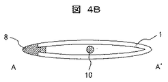
図4Aおよび図4Bに本発明の別の実施例である風力発電装置におけるブレードの先端部近傍を示す。図4Bは図4AにおけるA−A’断面を示している。実施例4における風力発電装置の全体構成については、上記の実施例1乃至実施例3で説明した部分と共通する部分について、その詳細な説明を省略して説明する。 4A and 4B show the vicinity of the tip of a blade in a wind turbine generator according to another embodiment of the present invention. FIG. 4B shows an A-A ′ cross section in FIG. 4A. About the whole structure of the wind power generator in Example 4, about the part which is common in the part demonstrated in said Example 1 thru | or Example 3, the detailed description is abbreviate | omitted and demonstrated.
実施例4における風力発電装置のブレード1は、図4Aに示すようにブレード1の先端部近傍に第一の受雷部であるレセプタ5が設けられている。また、ブレード1の回転方向においてレセプタ5よりも後ろ側すなわちブレード1の後縁側表面には、第一の受雷部となるレセプタ5と電気的に接続された第二の受雷部である導電材8がブレード1の後縁に沿って、第一の受雷部であるレセプタ5からブレード1のハブ2方向に延在するように設けられている。
As shown in FIG. 4A, the
また、図4Aに波線で示すように、ブレード1の内部には導電材10が設けられており、レセプタ5は導電材10と電気的に接続され、落雷時に受容した落雷を導電材10を介して、アースに放電する。なお、図4Aには明示されていないが、図1乃至図4における構造材6のようなブレード1の骨格材を導電材10とは別個に設けても良い。実施例4では、第一の受雷部であるレセプタ5と第二の受雷部である導電材8が一体化した形で形成されている。つまり、レセプタ5の後縁側をブレード1の後縁に沿って伸ばしたような形に形成されている。
4A, a
また、図4Bに示すように、図4のA−A’断面においては、第二の受雷部である導電材8がブレード1の後縁側において、ブレード1に嵌合されるように形成されている。本実施例のように、ブレード1の先端部近傍に第一の受雷部となるレセプタ5およびブレード1の後縁側に第二の受雷部となる導電材8を設けることで、単にレセプタ5をブレード1の先端部で拡大して設けた場合と比較して、より軽量化して設けることができる。
As shown in FIG. 4B, in the AA ′ cross section of FIG. 4, the
レセプタ5および導電材8の材質としては、例えば、腐食に強く、導電率の高いアルミニウム(Al)材やステンレス鋼(SUS)材を用いるのが好適である。
As the material of the
ここで、実施例1と同様に、ブレード1の後縁14に沿って、レセプタ5からブレード1のハブ2方向に延在するように設けられる導電材8の長さは、風力発電装置の規模やブレード形状(翼形状)にもよるが、30cmから100cm程度の長さで設けることにより、より効果的にブレード1の後縁14側に対する落雷を受容することができる。
Here, as in the first embodiment, the length of the
実施例4の風力発電装置によれば、必要以上にブレードの重量を増やすことなく、落雷時の落雷をより効果的に受容し、落雷つまり雷電流をアースへ放電することができ、ブレード1に対するダメージを最小限に抑えることができる。これにより、落雷による故障や事故が少なく、信頼性の高い風力発電装置を実現することが可能となる。 According to the wind turbine generator of the fourth embodiment, it is possible to more effectively receive a lightning strike during a lightning strike without increasing the weight of the blade more than necessary, and to discharge the lightning strike, that is, the lightning current to the ground. Damage can be minimized. As a result, it is possible to realize a highly reliable wind power generator with few failures and accidents due to lightning strikes.
図5に本発明の別の実施例である風力発電装置におけるブレードの先端部近傍を示す。実施例5における風力発電装置の全体構成については、上記の実施例1乃至実施例4で説明した部分と共通する部分について、その詳細な説明を省略して説明する。 FIG. 5 shows the vicinity of the tip of a blade in a wind turbine generator according to another embodiment of the present invention. About the whole structure of the wind power generator in Example 5, about the part which is common in the part demonstrated in said Example 1 thru | or Example 4, the detailed description is abbreviate | omitted and demonstrated.
実施例5おける風力発電装置のブレード1は、実施例4において、第二の受雷部となる導電材8のハブ2側の端部が中間レセプタ9を介して、導電材10と電気的に接続されている点において異なる。また、ブレード1の後縁側に延在してもうけられた第二の受雷部となる導電材8に沿うように、導電材8と電気的に接続された導電材10がブレード1の内部に形成されている点も実施例4と異なっている。つまり、第二の受雷部となる導電材8は、ブレード1の表面において、レセプタ5から離間して設けられている中間セレプタ9とレセプタ5を繋ぐように設けられている。実施例5のように、第一の受雷部であるレセプタ5および第二の受雷部である導電材8を設け、さらに第二の受雷部である導電材8のハブ2方向端部を中間レセプタ9を介してアースに接続することにより、落雷した際に第二の受雷部である導電材8のハブ2側の端部と導電材10とがショートするのを抑制することができ、ショートによるブレード1の割れやひび等のダメージを防止することができる。また、このような構造とすることで、一体化して形成された第一の受雷部および第二の受雷部すなわちレセプタ5と導電材8と、ブレード1との間の接合の補強効果も期待できる。
The
実施例5におけるレセプタ5および導電材8の材質としては、実施例4と同様に、腐食に強く、導電率の高いアルミニウム(Al)材やステンレス鋼(SUS)材を用いるのが好適である。
As materials of the
ここで、実施例1と同様に、ブレード1の後縁14に沿って、レセプタ5からブレード1のハブ2方向に延在するように設けられる導電材8の長さは、風力発電装置の規模やブレード形状(翼形状)にもよるが、30cmから100cm程度の長さで設けることにより、より効果的にブレード1の後縁14側に対する落雷を受容することができる。
Here, as in the first embodiment, the length of the
実施例5の風力発電装置によれば、必要以上にブレードの重量を増やすことなく、落雷時の落雷をより効果的に受容し、落雷つまり雷電流をアースへ放電することができ、ブレード1に対するダメージを最小限に抑えることができる。これにより、落雷による故障や事故が少なく、信頼性の高い風力発電装置を実現することが可能となる。 According to the wind turbine generator of the fifth embodiment, it is possible to more effectively receive a lightning strike during a lightning strike without increasing the weight of the blade more than necessary, and to discharge the lightning strike, that is, the lightning current to the ground. Damage can be minimized. As a result, it is possible to realize a highly reliable wind power generator with few failures and accidents due to lightning strikes.
図6に本発明の別の実施例である風力発電装置におけるブレードの先端部近傍を示す。実施例6における風力発電装置の全体構成については、上記の実施例1乃至実施例5で説明した部分と共通する部分について、その詳細な説明を省略して説明する。 FIG. 6 shows the vicinity of the tip of a blade in a wind turbine generator according to another embodiment of the present invention. About the whole structure of the wind power generator in Example 6, about the part which is common in the part demonstrated in said Example 1 thru | or Example 5, the detailed description is abbreviate | omitted and demonstrated.
実施例6おける風力発電装置のブレード1は、先端部近傍にレセプタ5が設けられている。レセプタ5は、ブレード1の後縁14側表面において、ブレード1の後縁14に沿って、ブレード1のハブ2方向に延在するように設けられ、かつ、ブレード1の前縁13側表面において、ブレード1の前縁13に沿って、ブレード1のハブ2方向に延在するように設けられ、ブレード1の後縁14側表面における受雷部すなわちレセプタ5の端部は、ブレード1の前縁13側表面における受雷部すなわちレセプタ5の端部よりもハブ2方向に長く設けられている。実施例6のようなレセプタ5の形状を採用することで、単にレセプタ5をブレード1の先端部で拡大して設けた場合と比較して、より軽量化して設けることができる。
The
実施例6におけるレセプタ5および導電材8の材質としては、実施例4と同様に、腐食に強く、導電率の高いアルミニウム(Al)材やステンレス鋼(SUS)材を用いるのが好適である。
As materials of the
ここで、ブレード1の後縁14側表面において、ブレード1の後縁14に沿って、ブレード1のハブ2方向に延在するように設けられるレセプタ5の長さは、風力発電装置の規模やブレード形状(翼形状)にもよるが、30cmから100cm程度の長さで設けることにより、より効果的にブレード1の後縁14側に対する落雷を受容することができる。
Here, on the surface of the
実施例6の風力発電装置によれば、必要以上にブレードの重量を増やすことなく、落雷時の落雷をより効果的に受容し、落雷つまり雷電流をアースへ放電することができ、ブレード1に対するダメージを最小限に抑えることができる。これにより、落雷による故障や事故が少なく、信頼性の高い風力発電装置を実現することが可能となる。 According to the wind turbine generator of Example 6, it is possible to more effectively receive a lightning strike during a lightning strike without increasing the weight of the blade more than necessary, and to discharge the lightning strike, that is, the lightning current to the ground. Damage can be minimized. As a result, it is possible to realize a highly reliable wind power generator with few failures and accidents due to lightning strikes.
なお、本発明は上記した実施例に限定されるものではなく、様々な変形例が含まれる。例えば、上記した実施例は本発明を分かりやすく説明するために詳細に説明したものであり、必ずしも説明した全ての構成を備えるものに限定されるものではない。また、ある実施例の構成の一部を他の実施例の構成に置き換えることが可能であり、また、ある実施例の構成に他の実施例の構成を加えることも可能である。また、各実施例の構成の一部について、他の構成の追加・削除・置換をすることが可能である。 In addition, this invention is not limited to an above-described Example, Various modifications are included. For example, the above-described embodiments have been described in detail for easy understanding of the present invention, and are not necessarily limited to those having all the configurations described. Further, a part of the configuration of one embodiment can be replaced with the configuration of another embodiment, and the configuration of another embodiment can be added to the configuration of one embodiment. Further, it is possible to add, delete, and replace other configurations for a part of the configuration of each embodiment.
1,1a,1b,1c…ブレード、2…ハブ、3…ナセル、4…タワー、5…レセプタ、6…構造材、7…ケーブル、8,10…導電材、9…中間レセプタ、11…ダメージ部、12…落雷、13…前縁、14…後縁。 1, 1a, 1b, 1c ... blade, 2 ... hub, 3 ... nacelle, 4 ... tower, 5 ... receptor, 6 ... structural material, 7 ... cable, 8,10 ... conductive material, 9 ... intermediate receptor, 11 ... damage Part, 12 ... Lightning strike, 13 ... Leading edge, 14 ... Trailing edge.
Claims (13)
前記タワー上に設けられ、前記発電機を内蔵するナセルと、
前記ナセルの一端に設けられ、風を受けて回転エネルギーへ変換するハブおよびブレードからなるロータと、を有する風力発電装置であって、
前記ブレードの先端部近傍に設けられ、落雷時に落雷を受容する受雷部と、
前記ブレードの後縁側表面に設けられ、前記受雷部と電気的に接続された金属箔と、を備えることを特徴とする風力発電装置。 A tower that is installed on the ground or the ocean and serves as a prop of the generator,
A nacelle provided on the tower and containing the generator;
A wind turbine generator provided at one end of the nacelle and having a rotor comprising a hub and blades that receive wind and convert it into rotational energy,
A lightning receiving portion that is provided near the tip of the blade, and that receives lightning during a lightning strike,
A wind power generator comprising: a metal foil provided on a rear edge side surface of the blade and electrically connected to the lightning receiving portion.
前記金属箔は、前記ブレードの表面において、前記受雷部と前記中間受雷部を繋ぐように設けられていることを特徴とする請求項2に記載の風力発電装置。 An intermediate lightning receiving portion provided near the trailing edge of the blade and electrically connected to the lightning receiving portion via a conductive material in the blade;
The wind power generator according to claim 2, wherein the metal foil is provided on the surface of the blade so as to connect the lightning receiving portion and the intermediate lightning receiving portion.
前記金属箔は、前記ブレードの後縁と前記中間受雷部を繋ぐように設けられ、
前記ブレードの表面において、前記金属箔の前記ブレードの後縁側端部と前記受雷部が離間して設けられていることを特徴とする請求項1に記載の風力発電装置。 An intermediate lightning receiving portion provided near the trailing edge of the blade and electrically connected to the lightning receiving portion via a conductive material in the blade;
The metal foil is provided so as to connect the rear edge of the blade and the intermediate lightning receiver,
2. The wind power generator according to claim 1, wherein a rear edge side end portion of the blade of the metal foil and the lightning receiving portion are provided apart from each other on a surface of the blade.
前記タワー上に設けられ、前記発電機を内蔵するナセルと、
前記ナセルの一端に設けられ、風を受けて回転エネルギーへ変換するハブおよびブレードからなるロータと、を有する風力発電装置であって、
前記ブレードの先端部近傍に設けられ、落雷時に落雷を受容する第一の受雷部と、
前記ブレードの後縁側表面に設けられ、前記第一の受雷部と電気的に接続された第二の受雷部と、を備えることを特徴とする風力発電装置。 A tower that is installed on the ground or the ocean and serves as a prop of the generator,
A nacelle provided on the tower and containing the generator;
A wind turbine generator provided at one end of the nacelle and having a rotor comprising a hub and blades that receive wind and convert it into rotational energy,
A first lightning receiving portion that is provided near the tip of the blade and receives a lightning strike during a lightning strike;
A wind power generator comprising: a second lightning receiving portion provided on a rear edge side surface of the blade and electrically connected to the first lightning receiving portion.
前記第二の受雷部は、前記ブレードの表面において、前記中間受雷部と繋ぐように設けられていることを特徴とする請求項8に記載の風力発電装置。 An intermediate lightning portion provided near the rear edge of the blade and electrically connected to the first lightning portion via a conductive material in the blade;
The wind power generator according to claim 8, wherein the second lightning receiving portion is provided on the surface of the blade so as to be connected to the intermediate lightning receiving portion.
前記タワー上に設けられ、前記発電機を内蔵するナセルと、
前記ナセルの一端に設けられ、風を受けて回転エネルギーへ変換するハブおよびブレードからなるロータと、を有する風力発電装置であって、
前記ブレードの先端部近傍に設けられ、落雷時に落雷を受容する受雷部と、を備え、
前記受雷部は、前記ブレードの後縁側表面において、前記ブレードの後縁に沿って、前記ブレードの前記ハブ方向に延在するように設けられ、かつ、前記ブレードの前縁側表面において、前記ブレードの前縁に沿って、前記ブレードの前記ハブ方向に延在するように設けられ、
前記ブレードの後縁側表面における前記受雷部の端部は、前記ブレードの前縁側表面における前記受雷部の端部よりも前記ハブ方向に長く設けられていることを特徴とする風力発電装置。 A tower that is installed on the ground or the ocean and serves as a prop of the generator,
A nacelle provided on the tower and containing the generator;
A wind turbine generator provided at one end of the nacelle and having a rotor comprising a hub and blades that receive wind and convert it into rotational energy,
A lightning receiving portion provided near the tip of the blade and receiving a lightning strike during a lightning strike,
The lightning receiving portion is provided on the rear edge side surface of the blade so as to extend along the rear edge of the blade toward the hub of the blade, and on the front edge side surface of the blade, the blade Extending along the leading edge of the blade toward the hub of the blade,
The wind power generator according to claim 1, wherein an end portion of the lightning receiving portion on the rear edge side surface of the blade is provided longer in the hub direction than an end portion of the lightning receiving portion on the front edge side surface of the blade.
Priority Applications (3)
| Application Number | Priority Date | Filing Date | Title |
|---|---|---|---|
| JP2014005372A JP2015132245A (en) | 2014-01-15 | 2014-01-15 | Wind power generator |
| TW103134563A TWI554683B (en) | 2014-01-15 | 2014-10-03 | Wind power plant |
| DE102015200370.1A DE102015200370A1 (en) | 2014-01-15 | 2015-01-13 | WIND POWER GENERATOR |
Applications Claiming Priority (1)
| Application Number | Priority Date | Filing Date | Title |
|---|---|---|---|
| JP2014005372A JP2015132245A (en) | 2014-01-15 | 2014-01-15 | Wind power generator |
Publications (1)
| Publication Number | Publication Date |
|---|---|
| JP2015132245A true JP2015132245A (en) | 2015-07-23 |
Family
ID=53485158
Family Applications (1)
| Application Number | Title | Priority Date | Filing Date |
|---|---|---|---|
| JP2014005372A Pending JP2015132245A (en) | 2014-01-15 | 2014-01-15 | Wind power generator |
Country Status (3)
| Country | Link |
|---|---|
| JP (1) | JP2015132245A (en) |
| DE (1) | DE102015200370A1 (en) |
| TW (1) | TWI554683B (en) |
Cited By (5)
| Publication number | Priority date | Publication date | Assignee | Title |
|---|---|---|---|---|
| USD803163S1 (en) | 2016-05-13 | 2017-11-21 | Erico International Corporation | Tip receptor mount for lightning protection systems |
| EP3361091A1 (en) | 2017-02-10 | 2018-08-15 | MHI Vestas Offshore Wind A/S | Wind turbine power generation facility and method of operating the same |
| US10344743B2 (en) | 2016-05-13 | 2019-07-09 | Erico International Corporation | Lightning protection system and method for wind turbine blades |
| JP2020529547A (en) * | 2017-08-25 | 2020-10-08 | ヴォッベン プロパティーズ ゲーエムベーハー | Wind Turbine Rotor Blades and Wind Turbine Rotor Blade Lightning Protection Systems |
| JP7061327B1 (en) | 2021-03-19 | 2022-04-28 | 国立大学法人東海国立大学機構 | Wind power generation equipment and its rotary blades and control method for wind power generation equipment |
Families Citing this family (5)
| Publication number | Priority date | Publication date | Assignee | Title |
|---|---|---|---|---|
| DK3246562T3 (en) | 2016-05-18 | 2019-05-13 | Nordex Energy Gmbh | Lightning trap for a wind turbine rotor blade |
| US10871150B2 (en) | 2016-07-29 | 2020-12-22 | Vestas Wind Systems A/S | Wind turbine blade having a lightning tip receptor |
| CN109642552B (en) | 2016-07-29 | 2021-05-25 | 维斯塔斯风力系统有限公司 | Wind turbine blade with lightning tip receiver |
| DK3615791T3 (en) * | 2017-04-26 | 2022-06-27 | Vestas Wind Sys As | WIND TURBLE WINGS AND WIND TURBLE POWER GENERATION APPLIANCE |
| PT3879091T (en) * | 2020-03-13 | 2024-06-14 | Siemens Gamesa Renewable Energy As | Wind turbine blade assembly and method for manufacturing a wind turbine assembly |
Citations (6)
| Publication number | Priority date | Publication date | Assignee | Title |
|---|---|---|---|---|
| JP2008115783A (en) * | 2006-11-06 | 2008-05-22 | Fuji Heavy Ind Ltd | Windmill blade |
| JP2010223147A (en) * | 2009-03-25 | 2010-10-07 | Mekatoro Giken:Kk | Structure for preventing lightning damage to rotor blade of wind power generation device, and method for the same |
| WO2011077970A1 (en) * | 2009-12-24 | 2011-06-30 | 三菱重工業株式会社 | Wind wheel blade and wind-driven electricity generation device with same |
| JP2012246815A (en) * | 2011-05-26 | 2012-12-13 | Japan Steel Works Ltd:The | Wind power generation blade |
| WO2013007267A1 (en) * | 2011-07-14 | 2013-01-17 | Vestas Wind Systems A/S | A wind turbine blade |
| WO2013084634A1 (en) * | 2011-12-09 | 2013-06-13 | 三菱重工業株式会社 | Wind turbine and wind power generation device |
Family Cites Families (1)
| Publication number | Priority date | Publication date | Assignee | Title |
|---|---|---|---|---|
| JP2012246812A (en) * | 2011-05-26 | 2012-12-13 | Japan Steel Works Ltd:The | Wind power generation blade |
-
2014
- 2014-01-15 JP JP2014005372A patent/JP2015132245A/en active Pending
- 2014-10-03 TW TW103134563A patent/TWI554683B/en active
-
2015
- 2015-01-13 DE DE102015200370.1A patent/DE102015200370A1/en not_active Withdrawn
Patent Citations (6)
| Publication number | Priority date | Publication date | Assignee | Title |
|---|---|---|---|---|
| JP2008115783A (en) * | 2006-11-06 | 2008-05-22 | Fuji Heavy Ind Ltd | Windmill blade |
| JP2010223147A (en) * | 2009-03-25 | 2010-10-07 | Mekatoro Giken:Kk | Structure for preventing lightning damage to rotor blade of wind power generation device, and method for the same |
| WO2011077970A1 (en) * | 2009-12-24 | 2011-06-30 | 三菱重工業株式会社 | Wind wheel blade and wind-driven electricity generation device with same |
| JP2012246815A (en) * | 2011-05-26 | 2012-12-13 | Japan Steel Works Ltd:The | Wind power generation blade |
| WO2013007267A1 (en) * | 2011-07-14 | 2013-01-17 | Vestas Wind Systems A/S | A wind turbine blade |
| WO2013084634A1 (en) * | 2011-12-09 | 2013-06-13 | 三菱重工業株式会社 | Wind turbine and wind power generation device |
Cited By (10)
| Publication number | Priority date | Publication date | Assignee | Title |
|---|---|---|---|---|
| USD803163S1 (en) | 2016-05-13 | 2017-11-21 | Erico International Corporation | Tip receptor mount for lightning protection systems |
| US10344743B2 (en) | 2016-05-13 | 2019-07-09 | Erico International Corporation | Lightning protection system and method for wind turbine blades |
| USD881136S1 (en) | 2016-05-13 | 2020-04-14 | Erico International Corporation | Tip receptor mount for lightning protection systems |
| US11078889B2 (en) | 2016-05-13 | 2021-08-03 | Erico International Corporation | Lightning protection system and method for wind turbine blades |
| EP3361091A1 (en) | 2017-02-10 | 2018-08-15 | MHI Vestas Offshore Wind A/S | Wind turbine power generation facility and method of operating the same |
| US10767629B2 (en) | 2017-02-10 | 2020-09-08 | Mhi Vestas Offshore Wind A/S | Wind turbine power generation facility and method of operating the same |
| JP2020529547A (en) * | 2017-08-25 | 2020-10-08 | ヴォッベン プロパティーズ ゲーエムベーハー | Wind Turbine Rotor Blades and Wind Turbine Rotor Blade Lightning Protection Systems |
| US11286912B2 (en) | 2017-08-25 | 2022-03-29 | Wobben Properties Gmbh | Wind turbine rotor blade and lightning protection system for a wind turbine rotor blade |
| JP7061327B1 (en) | 2021-03-19 | 2022-04-28 | 国立大学法人東海国立大学機構 | Wind power generation equipment and its rotary blades and control method for wind power generation equipment |
| JP2022145396A (en) * | 2021-03-19 | 2022-10-04 | 国立大学法人東海国立大学機構 | Wind power generation device, rotary blade thereof, and control method for wind power generation device |
Also Published As
| Publication number | Publication date |
|---|---|
| DE102015200370A1 (en) | 2015-07-16 |
| TW201534813A (en) | 2015-09-16 |
| TWI554683B (en) | 2016-10-21 |
Similar Documents
| Publication | Publication Date | Title |
|---|---|---|
| JP2015132245A (en) | Wind power generator | |
| JP5941174B1 (en) | Wind power generator | |
| US10584684B2 (en) | Wind turbine blades and potential equalization systems | |
| JP4580169B2 (en) | Split blade for windmill and lightning protection device for windmill | |
| CN102691630B (en) | A wind turbine blade | |
| EP2889477B1 (en) | Wind turbine lightning protection system and corresponding wind turbine rotor | |
| JP6209211B2 (en) | Wind turbine blade lightning bypass system | |
| JP5718928B2 (en) | Wind generator protection system against atmospheric discharge | |
| CN101233317B (en) | Lightning protection systems for wind turbines | |
| EP2889476B1 (en) | Wind turbine lightning protection system and corresponding wind turbine rotor | |
| JP5246506B2 (en) | Wind power generator rotor blade lightning damage prevention structure | |
| JP6657314B2 (en) | Wind turbine blade protection structure and method of forming the same | |
| CN101354016A (en) | Wind turbine protection | |
| EP3093487B1 (en) | Lightning protection system for wind turbine rotor blades | |
| JP2008115783A (en) | Windmill blade | |
| JP2012246812A (en) | Wind power generation blade | |
| JP2012246815A (en) | Wind power generation blade | |
| CN108223306B (en) | A lightning protection device covering the surface of wind turbine blades | |
| EP2589803A1 (en) | Lightning arrester structure for wind generator blade | |
| JP2019218863A (en) | Windmill blade protection structure and method for forming the same | |
| CN108223305B (en) | Electrode lightning receiving device for wind turbine generator blade | |
| JP4451726B2 (en) | Split blade for windmill and lightning protection device for windmill | |
| CN103527421B (en) | Blade lightning protection device of offshore wind generating set | |
| JP2019173580A (en) | Wind turbine generator system and its control method | |
| JP2017203432A (en) | Windmill blade |
Legal Events
| Date | Code | Title | Description |
|---|---|---|---|
| A621 | Written request for application examination |
Free format text: JAPANESE INTERMEDIATE CODE: A621 Effective date: 20160708 |
|
| A977 | Report on retrieval |
Free format text: JAPANESE INTERMEDIATE CODE: A971007 Effective date: 20170405 |
|
| A131 | Notification of reasons for refusal |
Free format text: JAPANESE INTERMEDIATE CODE: A131 Effective date: 20170418 |
|
| A521 | Request for written amendment filed |
Free format text: JAPANESE INTERMEDIATE CODE: A523 Effective date: 20170619 |
|
| A02 | Decision of refusal |
Free format text: JAPANESE INTERMEDIATE CODE: A02 Effective date: 20171003 |
|
| A521 | Request for written amendment filed |
Free format text: JAPANESE INTERMEDIATE CODE: A523 Effective date: 20171227 |
|
| A911 | Transfer to examiner for re-examination before appeal (zenchi) |
Free format text: JAPANESE INTERMEDIATE CODE: A911 Effective date: 20180110 |
|
| A912 | Re-examination (zenchi) completed and case transferred to appeal board |
Free format text: JAPANESE INTERMEDIATE CODE: A912 Effective date: 20180316 |
|
| A521 | Request for written amendment filed |
Free format text: JAPANESE INTERMEDIATE CODE: A523 Effective date: 20181101 |