JP2015131273A - Jig sorting apparatus and jig sorting method - Google Patents
Jig sorting apparatus and jig sorting method Download PDFInfo
- Publication number
- JP2015131273A JP2015131273A JP2014004103A JP2014004103A JP2015131273A JP 2015131273 A JP2015131273 A JP 2015131273A JP 2014004103 A JP2014004103 A JP 2014004103A JP 2014004103 A JP2014004103 A JP 2014004103A JP 2015131273 A JP2015131273 A JP 2015131273A
- Authority
- JP
- Japan
- Prior art keywords
- particle mixture
- fluid
- jig
- particles
- flow
- Prior art date
- Legal status (The legal status is an assumption and is not a legal conclusion. Google has not performed a legal analysis and makes no representation as to the accuracy of the status listed.)
- Granted
Links
Images


Landscapes
- Separation Of Solids By Using Liquids Or Pneumatic Power (AREA)
Abstract
【課題】簡単な機構で粒子混合物を上下動させて、密度の異なる粒子毎に選別可能なジグ選別装置、及びジグ選別方法を提供する。【解決手段】密度が異なる複数の粒子が混合した粒子混合物Pの流送方向に間隔を置いて流体を噴出する複数の噴出口22を設け、粒子混合物を流送しながら、複数の噴出口により搬送される粒子混合物へ向けて流体Wを噴出させることにより噴出口の数だけ繰り返し上昇させては落下させて密度の異なる粒子毎に成層させて分類する。【選択図】図1The present invention provides a jig sorting apparatus and a jig sorting method that can sort a particle mixture by moving a particle mixture up and down with a simple mechanism. SOLUTION: A plurality of jet ports 22 for jetting a fluid at intervals in the flow direction of a particle mixture P in which a plurality of particles having different densities are mixed are provided, and the particle mixture is fed by a plurality of jet ports while feeding the particle mixture. By ejecting the fluid W toward the particle mixture to be conveyed, the fluid W is repeatedly raised and dropped by the number of ejection ports, and is stratified for each particle having a different density. [Selection] Figure 1
Description
この発明は、密度の異なる複数の粒子が混合した粒子混合物をジグ選別方法により各粒子に選別する選別装置、及び選別方法に関する。 The present invention relates to a sorting apparatus and a sorting method for sorting a particle mixture in which a plurality of particles having different densities are mixed into each particle by a jig sorting method.
従来、密度の異なる複数の粒子を含む粒子混合物を各粒子に選別する方法としてジグ選別なる選別方法が用いられている。このジグ選別は、流体中で粒子が沈降し始めた沈降初期においては、粒子の沈降速度が粒径に影響されず概ね密度のみにより決定されることを利用している。 2. Description of the Related Art Conventionally, a sorting method using jig sorting is used as a method for sorting a particle mixture including a plurality of particles having different densities into particles. This jig sorting utilizes the fact that, in the initial stage of sedimentation when particles begin to settle in the fluid, the sedimentation rate of the particles is largely determined only by the density without being influenced by the particle size.
この原理を簡単に説明すると、まず、流体中で粒子にかかる力は、重力・浮力・抵抗力であるから、粒子が球形であると仮定すると下記式(1)の運動方程式が得られる。
<式1>
(πx3/6)・ρP・(dv/dt)=(πx3/6)・(ρP-ρf)g−R
…(1)
ここで、xは粒子の直径、ρPは粒子の密度、vは粒子の沈降速度、tは時間、ρfは流体の密度、gは重力加速度、Rは抵抗を表している。
(1)式において、粒子の沈降初期では沈降速度が小さく、抵抗R=0と近似できるので、同方程式(1)の解は下記式(2)となり、沈降速度が粒子径と無関係で密度のみの関数となる。
<式2>
v=(1−ρf/ρP)gt …(2)
即ち、粒子の沈降初期では密度の大きい粒子が密度の小さい粒子よりも沈降速度が速くなるため、粒子混合物を上昇させた後沈降させることで密度の大きい粒子を密度の小さい粒子より下側に成層させて密度ごとに分類することが可能となる。
This principle will be briefly explained. First, since the force applied to the particles in the fluid is gravity, buoyancy, and resistance, assuming that the particles are spherical, the equation of motion of the following equation (1) is obtained.
<
(Πx 3/6) · ρ P · (dv / dt) = (
... (1)
Here, x is the particle diameter, ρ P is the particle density, v is the particle settling velocity, t is time, ρ f is the fluid density, g is the gravitational acceleration, and R is the resistance.
In the equation (1), since the sedimentation rate is small at the initial stage of particle sedimentation and can be approximated to the resistance R = 0, the solution of the equation (1) is the following equation (2). Is a function of
<
v = (1−ρ f / ρ P ) gt (2)
In other words, since particles with a high density have a higher settling speed than particles with a low density in the early stage of particle settling, particles with a high density are stratified below particles with a low density by raising the particle mixture and then settling. It is possible to classify by density.
ジグ選別方法を利用した装置としては、例えば、水没させたプレート上に粒子混合物を載置し、水圧により当該プレートを上下に揺動させて粒子混合物に上下動を加えるROMジグ装置や、同様に水没させた固定プレート上に粒子混合物を載置し、固定プレートの下方に設けた空気室に圧縮空気を周期的に入・排気することよって発生させる上下水流によって粒子混合物に上下動を加えるBATACジグ装置が用いられている(非特許文献1参照)。 As an apparatus using the jig sorting method, for example, a ROM jig apparatus in which a particle mixture is placed on a submerged plate and the plate is swung up and down by water pressure to vertically move the particle mixture. A BATAC jig that places a particle mixture on a submerged fixed plate and moves the particle mixture up and down by a vertical water flow generated by periodically entering and exhausting compressed air into an air chamber provided below the fixed plate. The apparatus is used (refer nonpatent literature 1).
しかし、ROMジグ装置やBATACジグ装置は、プレートを上下動させる機構や上下水流を生み出すための機構が必要であり、装置が複雑で過大となるためコスト高になるという問題が有る。
本発明は、上記課題に鑑みてなされたものであり、簡単な構造で粒子混合物を上下動させることが可能なジグ選別装置、及びジグ選別方法の提供を目的とする。
However, the ROM jig apparatus and the BATAC jig apparatus require a mechanism for moving the plate up and down and a mechanism for generating a vertical water flow, and there is a problem that the apparatus becomes complicated and excessively expensive.
The present invention has been made in view of the above problems, and an object of the present invention is to provide a jig sorting apparatus and a jig sorting method capable of moving a particle mixture up and down with a simple structure.
上記課題を解決するためになされた発明は、密度が異なる複数の粒子が混合した粒子混合物に流体の噴流を間欠的に複数回加えて当該粒子混合物を繰り返し上昇させては落下させることにより密度の異なる粒子毎に成層させて分類するジグ選別装置であって、粒子混合物を流送する流送路と、前記流送路の流送方向に間隔を開けて設けられ、流送される前記粒子混合物に向けて流体を噴出させる複数の噴出口とを備え、前記複数の噴出口から前記流体を連続的に噴出しながら前記粒子混合物を流送させることを特徴とする。 The invention made in order to solve the above-mentioned problem is that the density of the density is increased by repeatedly adding the fluid jet to the particle mixture in which a plurality of particles having different densities are mixed, and repeatedly raising and dropping the particle mixture. A jig sorting device that stratifies and classifies different particles, a flow path for feeding a particle mixture, and the particle mixture that is provided and spaced apart in the flow direction of the flow path A plurality of outlets for ejecting a fluid toward the surface, and the particle mixture is flowed in while continuously ejecting the fluid from the plurality of outlets.
このように、流送路の流送方向に間隔を開けて設けた噴出口から連続的に流体を噴出させながら粒子混合物を流送させることにより、粒子混合物が噴流を受ける位置に差し掛かる度に上昇させられては下降する運動を繰り返すため、流体を間欠的に噴出させるための機構を省略することができる。因みに、上記従来のジグ選別装置では、プレートや水流の上下動の各回が粒子混合物に加えるべき複数回の上下動の各回を担うのに対し、本発明では、複数の噴出口からの各噴流が粒子混合物に加えるべき複数回の上下動の各回を担うこととなる。 In this way, every time the particle mixture reaches the position where the particle mixture receives the jet flow by flowing the particle mixture while continuously ejecting the fluid from the jet port provided at intervals in the flow direction of the flow path. Since the movement of descending is repeated when it is raised, a mechanism for intermittently ejecting fluid can be omitted. Incidentally, in the above-described conventional jig sorting apparatus, each time of vertical movement of the plate and water flow bears multiple times of vertical movement that should be added to the particle mixture, whereas in the present invention, each jet flow from a plurality of jet outlets It will be responsible for each round of up and down movements to be added to the particle mixture.
また、前記流送路は、流送方向に下る傾斜路であることが好ましい。こうすることで、重力により粒子混合物を流送させることができる。 Moreover, it is preferable that the flow path is an inclined path that goes down in the flow direction. By doing so, the particle mixture can be fed by gravity.
また、前記流送路は、管又は樋からなり、前記流体として液体が用いられるよう構成されていることが好ましい。こうすることで、噴出口から噴出した流体が流送路を流れることを利用して、粒子混合物を流送させることができる。 Moreover, it is preferable that the said flow path consists of a pipe | tube or a soot, and is comprised so that a liquid may be used as said fluid. By carrying out like this, a particle mixture can be made to flow using the fluid which spouted from the jet nozzle flows through a flow path.
前記流送路は、内壁の下部が流送方向に垂直な幅方向の両側から中央に向けて深くなる断面形状を有し、前記複数の噴出口が、前記流送路の幅方向の中央に設けられていることが好ましい。こうすることで、噴出された流体により舞い上げられた粒子混合物が、噴出口のある流送路の中央に戻るよう対流するため、効率よく粒子混合物に上下運動をさせることができる。 The flow path has a cross-sectional shape in which the lower part of the inner wall is deepened from both sides in the width direction perpendicular to the flow direction toward the center, and the plurality of jet ports are formed at the center in the width direction of the flow path. It is preferable to be provided. By doing so, the particle mixture that has been lifted up by the jetted fluid convects back to the center of the inflow channel with the jet outlet, so that the particle mixture can be efficiently moved up and down.
前記流送路は、傾斜角度を変更可能であることが好ましい。こうすることで、粒子を分類するのに最適の上下運動を粒子混合物にさせるべく流送路の傾斜角度を調節することができる。 The flow path is preferably capable of changing an inclination angle. In this way, the inclination angle of the flow path can be adjusted so that the particle mixture has the optimum vertical movement for classifying the particles.
本発明は、密度が異なる複数の粒子が混合した粒子混合物に流体の上昇流を間欠的に複数回加えて粒子混合物を繰り返し上昇させては落下させることで密度の異なる粒子毎に成層させて分類するジグ選別方法であって、粒子混合物の流送方向に間隔を置いて流体を噴出する複数の噴出口を設け、粒子混合物を流送しながら、前記複数の噴出口により搬送される粒子混合物に向けて流体を噴出させることを特徴とする方法を含む。
ここで、「流体」とは、流動性を有する全ての物質を含み、気体、液体又はこれらの混合物の他、気体または液体に粉末状の固体等が混合されたようなものを含む。「流送」とは、粒子混合物をベルトコンベアーや気体若しくは液体の流れ等により強制的に流送するものと、自重により粒子混合物が自然に流送されるものの両方を含むものとする。また、「噴出口」とは、1孔から成るものに限らず、流送路の流送方向の実質的に同じ位置において、多数の孔がある面積に集合したものや流送路の幅方向に直線状に並んだもの等も含むものとする。
The present invention categorizes each particle having different density by stratifying the particle mixture by repeatedly adding the fluid upward flow several times to the particle mixture in which a plurality of particles having different densities are mixed and repeatedly raising and dropping the particle mixture. A plurality of jet nozzles for ejecting fluid at intervals in the flow direction of the particle mixture, and supplying the particle mixture conveyed by the plurality of jet nozzles while feeding the particle mixture. And a method characterized by ejecting fluid toward.
Here, the “fluid” includes all substances having fluidity, and includes a gas, a liquid, a mixture thereof, a gas or a liquid mixed with a powdered solid, or the like. “Feeding” includes both forcibly feeding the particle mixture by a belt conveyor, a gas or liquid flow, and the like, and those in which the particle mixture is naturally fed by its own weight. In addition, the “jet port” is not limited to one having a single hole, but is a collection of a large number of holes in substantially the same position in the flow direction of the flow path or the width direction of the flow path. It shall also include those arranged in a straight line.
以上説明したように、本発明のジグ選別装置及びジグ選別方法によれば、簡単な構造で密度の異なる粒子が混合した粒子混合物を上下動させることができる。 As described above, according to the jig sorting apparatus and the jig sorting method of the present invention, the particle mixture in which particles having different densities and a simple structure are mixed can be moved up and down.
(第1実施形態)
以下、適宜図面を用いながら本発明の実施形態について詳述する。図1は、本発明の第1実施形態に係るジグ選別装置1であり、密度の異なる2種の粒子が混合した粒子混合物Pをジグ選別法により分類する装置である。ジグ選別装置1は、流送管(特許請求の範囲における流送路)2と、流送管2の噴出口22から水(流体)Wを噴出させるべく貯留する貯留管3と、粒子混合物Pを排出する第1乃至第3の回収管41,42,43と、流送管2から水を排出する排水管5と、支持脚7とを主に備えている。
尚、本発明のジグ選別装置及びジグ選別方法は、以下の実施形態に限られるものではない。
(First embodiment)
Hereinafter, embodiments of the present invention will be described in detail with reference to the drawings as appropriate. FIG. 1 is a
The jig sorting device and jig sorting method of the present invention are not limited to the following embodiments.
流送管2は、円管により形成され、円管の延びる方向が粒子混合物の流送方向となる。流送管2は、流送方向上流側端部に粒子混合物を流入する流入口21を備え、流送方向下流側の端部が封じられて内部に水が溜まるよう構成されている。また、流送管2は、図1に示すように、周壁の断面の最も低い位置に、流送方向に沿って適宜の間隔を開けながら周壁を貫通する複数の噴出口22,22,…が設けられている。
The
流送管2の搬送方向下流側の周壁下面側から、3本の回収管41,42,43が分岐しており、流送管2と回収管41,…とは、分類された粒子を排出する第1乃至第3回収スリット23,24,25により連通している。回収スリット23,24,25は、図3に示すように、長手方向が流送管2の周方向に延びる矩形をなし、流送管2の断面の最も低い位置に設けられている。
Three
貯留管3は、図1に示すように、流送管2の複数の噴出口22,…を覆うようにして流送管2の外周に環装されている。貯留管3は両端が塞がれており、貯留管3と流送管2の周壁との間に噴出口22から噴射するべく水を貯留する空間が設けられている。貯留管2の周壁上部には、搬送方向の上流側と下流側の2つの位置から貯留管3内へ水を流入する送水管6が連結されている。
As shown in FIG. 1, the
排水管5は、回収スリット23,24,25よりもさらに下流側において、流送管2の周壁上面側から上方へ立ち上がるように分岐され、流送管2を通り抜けたのち排水管5からあふれ出る水を上部開口51から排出するとともに、管内に十分な水位を保持して流送管2内部が流入口21まで十分に水で満たされるよう適宜の長さに形成されている。
The drain pipe 5 is branched further downstream from the recovery slits 23, 24, and 25 so as to rise upward from the upper surface side of the peripheral wall of the
支持脚7は、ネジを緩めて長さを変えることで、流送管2の傾きを調節可能に設けられている。
The
次に、ジグ選別装置1により、密度の大きい粒子Aと密度の小さい粒子Bが混合した粒子混合物P(例えば、砂とアンスラサイト)が分類される仕組みについて、図1を用いて説明する。まず、送水管6から貯留管3内に水を流入させる。貯留管3内に流入した水は、流送管2の噴出口22,22,…から、流送管2内へ噴出し、流送管2内を満たしていく。流入口21まで、流送管2内に水が流入したら流入口21から粒子混合物Pを流入させる。
Next, a mechanism for classifying the particle mixture P (for example, sand and anthracite) in which the high density particles A and the low density particles B are mixed by the
流入口21から流送管2内に流入された粒子混合物Pは、流送方向下流側へと傾斜した流送管2内を自重により下り始める。粒子混合物Pが最上流側の噴出口22に差し掛かると、粒子混合物Pは噴出口22から略一定流量で連続的に噴出する水流により舞い上げられたのち自重により沈降する。この粒子が上昇から沈降に転じる沈降の初期においては、上述したように密度の大きい粒子Aは密度の小さい粒子Bより沈降速度が大きいため、粒子Bより先に沈降する。こうして、やや下層側に粒子Aが多く分布し、上層側に粒子Bが少なく分布するよう流送管2の内部に積層した粒子混合物Pは、自重及び水流により次の噴出口22まで流下する。そして、次の噴出口22に差し掛かると、粒子混合物Pは、再び噴出口から噴出する流水により舞い上げられては沈降する。以下、これが噴出口の数だけ繰り返されて、最終の噴出口22を通過した後は、粒子Aと粒子Bとが上下2層に概ね分離された状態となる。
The particle mixture P that has flowed into the
そして、上下2層に分離された粒子混合物Pが、さらに流送管2を流下して回収スリット23に差し掛かると、下側の層をなす粒子Aのうち上側の粒子Bとの境界部に積層したものを除いた下部に積層した粒子Aが回収スリット23から回収管41内へ流入する。次に、残りの粒子混合物Pが、次の回収スリット24に差し掛かると、粒子Aの層と粒子Bの層との境界部分にある粒子A及び粒子Bが、回収スリット24から回収管42内へ流入する。そして、最後に残った粒子Bが次の回収スリット25まで流下していき回収管43へ流入する。
Then, when the particle mixture P separated into the upper and lower two layers further flows down the
回収管41,42,43には、各2個ずつのバルブが設けられており、図1に示すように、上側のバルブ81,83,85を開にし、下側のバルブ82,84,86を閉にした状態で、上下のバルブ間に粒子を回収する。回収された粒子を次の工程へと移送する際には、上側のバルブ81,83,85を閉にして、下側のバルブ82,84,86を開にした状態で、ジェットポンプ101,102,103により移送する。図1において、符号91,92,93は、粒子移送用の流水を供給する給水管を示し、符号121,122,123は、ジェットポンプに加圧作動水を供給する駆動ポンプを示している。回収管41及び回収管43で回収された粒子A及び粒子Bは、移送管111,112により、洗浄や分級等の次の工程を行う装置へと搬送され、回収管42で回収された粒子混合物Pは、移送管113を通って再投入管130から流送管2の最上流へ再び投入され、再度分類処理される。
The
粒子混合物Pと異なる粒子混合物を選別するときは、流送管2の傾斜や噴出口22からの噴流の勢いを適宜調節する。
When selecting a particle mixture different from the particle mixture P, the inclination of the
上述したように、ジグ選別装置1では、複数の噴出口22が、流送方向上流側の噴出口から順に粒子混合物Pに噴流を加えることで、粒子混合物Pに間欠的に噴流が加えられるため、噴出口22から噴出させる水に脈動を加えたり間欠的に水を噴射させたりする必要がなく、水を脈動等させるための機構を必要とせず、装置を大幅に簡略化することができる。
As described above, in the
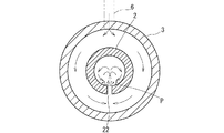
また、ジグ選別装置1は、図2に示すように、流送管2が円筒からなるため、流送方向に垂直な幅方向の断面にデッドスペースが生じにくく、スムーズに流体を対流させることができるため、効率的に粒子混合物を分離成層することができる。さらに、流送管2が幅方向の断面において両側から中央に向かって低くなり、その中央に噴出口22が設けられていることで、沈降した粒子混合物が噴出口のある流送路の中央に戻るため、効率よく粒子混合物を上下運動させることができる。加えて、流送管2の傾斜を調整することができるため、異なる粒子混合物を選別することができる。
Further, as shown in FIG. 2, in the
(第2実施形態)
次に、本発明の第2実施形態について説明する。第2実施形態において第1実施形態と共通する部分については同一の符号を付して説明を省略し、第2実施形態においても粒子Aと粒子Bとからなる粒子混合物Pを分類するものとする。
図4は、本発明の第2実施形態に係るジグ選別装置201の下流側部分を示している。ジグ選別装置201は、上流側の回収スリット223と下流側の回収スリット224とを備えている。回収スリット223、224は、第1実施形態の回収スリット23乃至25と同様の矩形状(図3参照)を有している。上流側の回収スリット223には、流送管2の軸芯方向にスライドして回収スリット223の幅を調節するスリット幅調節蓋250が設けられており、回収スリット223のやや下流側には、下側に層をなした粒子Aのみを遮断すべく粒子Aの層の厚さに合わせて上下にスライドする遮蔽板260が設けられている。
(Second Embodiment)
Next, a second embodiment of the present invention will be described. In the second embodiment, portions common to the first embodiment are denoted by the same reference numerals and description thereof is omitted, and the particle mixture P composed of particles A and particles B is also classified in the second embodiment. .
FIG. 4 shows a downstream portion of the
ジグ選別装置201は、カラーセンサーカメラ(不図示)とこのカラーセンサーカメラからの情報に基づき、駆動装置251、261を介して、スリット幅調節蓋250及び遮蔽板260の動作を制御する制御機構(不図示)とを備えており、回収スリット223近傍を流下する粒子混合物の画像から上下層の境界を判別しながら、下層の粒子Aが遮蔽板260を乗り越えないようにスリット幅調節蓋250により回収スリット223のスリット幅を調節するとともに、遮蔽板260の高さを調節するよう構成されている。このようなスリット幅調節蓋250と遮蔽板260とを備えることにより、粒子A、粒子Bをそれぞれ回収スリット223、224へ効率よく分類することができる。
The
(その他の実施形態)
本発明のジグ選別装置は上記の実施形態に限られるものではなく、例えば、流送路を水平、又は搬送方向下流側に上る傾斜路として、粒子混合物をベルトコンベアーで搬送するようにしてもよい。また、噴射する流体は、水に限らず、他の液体を用いてもよい。さらに、流体として気体を用いることもでき、気体中を搬送される粒子混合物に気体の噴流を加えてもよいし、液体中を搬送される粒子混合物に気体の噴流を加えることもできる。
流送路は、流体を液体とする場合、流体がこぼれなければ樋状に形成してもよい。また流送路を管にする場合は、円形管に限らず、楕円管や多角形管とすることもでき、こうすることによっても円形管と近似のスムーズな対流を流体及び粒子混合物にさせることができる。第1実施形態において、回収スリットを5つ、7つ、…と増やしてもよく、こうすることにより、3種、4種、…の混合物が含まれる粒子混合物を選別することができる。
また、第2実施形態において、カラーセンサーカメラの代わりに作業者の目視により、上下層の境界を判別しながらスリット幅調節蓋250や遮蔽板260を手動で制御するようにしてもよい。
(Other embodiments)
The jig sorting apparatus according to the present invention is not limited to the above-described embodiment. For example, the particle mixture may be transported by a belt conveyor using an inflow path as an inclined path that rises horizontally or downstream in the transport direction. . Further, the fluid to be ejected is not limited to water, and other liquids may be used. Further, a gas may be used as the fluid, and a gas jet may be added to the particle mixture transported in the gas, or a gas jet may be added to the particle mixture transported in the liquid.
When the fluid is a liquid, the flow path may be formed in a bowl shape if the fluid does not spill. In addition, when the flow path is a tube, it is not limited to a circular tube but can be an elliptical tube or a polygonal tube. By doing so, a smooth convection similar to that of a circular tube can be made into a fluid and particle mixture. Can do. In the first embodiment, the number of collection slits may be increased to five, seven,..., Whereby a particle mixture including a mixture of three, four,.
In the second embodiment, instead of the color sensor camera, the slit
以上説明したように、本発明に係るジグ選別装置及びジグ選別方法によれば、流体に脈動を与えるための機構を必要とせず装置の簡略化を図ることができるため、鉱物の選別やリサイクル用破砕材の材料選別、濾過材と被濾過材の選別等、異なる密度を有する粒子の混合物を選別する必要のある各種産業現場に、好適に採用することができる。 As described above, according to the jig sorting apparatus and the jig sorting method according to the present invention, since the apparatus can be simplified without requiring a mechanism for pulsating the fluid, it can be used for mineral sorting and recycling. The present invention can be suitably employed in various industrial sites where it is necessary to select a mixture of particles having different densities, such as material selection for crushed materials, filter material and filter material.
1,201 ジグ選別装置
2 流送管(流送路)
22 噴出口
P 粒子混合物
W 水(流体)
A,B 粒子
1,201
22 Spout P Particle mixture W Water (fluid)
A, B particles
Claims (6)
粒子混合物を流送する流送路と、
前記流送路の流送方向に間隔を開けて設けられ、流送される前記粒子混合物に向けて流体を噴出させる複数の噴出口と
を備え、
前記複数の噴出口から前記流体を連続的に噴出しながら前記粒子混合物を流送させることを特徴とするジグ選別装置。 A jig sorter that stratifies and classifies particles with different densities by adding a jet of fluid intermittently multiple times to a mixture of particles with different densities and repeatedly raising and dropping the mixture. Because
A flow path for flowing the particle mixture;
A plurality of spouts provided at intervals in the flow direction of the flow path, and ejecting fluid toward the particle mixture to be flowed,
A jig sorting apparatus, wherein the particle mixture is flowed while the fluid is continuously ejected from the plurality of ejection ports.
前記複数の噴出口が、前記流送路の幅方向の中央に設けられている請求項3に記載のジグ選別装置。 The flow path has a cross-sectional shape in which the lower part of the inner wall deepens from both sides in the width direction perpendicular to the flow direction toward the center,
The jig sorting device according to claim 3, wherein the plurality of jet nozzles are provided in the center in the width direction of the flow path.
粒子混合物の流送方向に間隔を置いて流体を噴出する複数の噴出口を設け、
粒子混合物を流送しながら、前記複数の噴出口により搬送される粒子混合物に向けて流体を噴出させることを特徴とするジグ選別方法。 A jig sorting method that stratifies and classifies particles with different densities by adding a fluid flow multiple times intermittently to a particle mixture of particles with different densities and repeatedly raising and dropping the particle mixture. Because
Provided with a plurality of jet outlets for jetting fluid at intervals in the flow direction of the particle mixture,
A jig selecting method, wherein a fluid is ejected toward the particle mixture conveyed by the plurality of ejection ports while the particle mixture is being fed.
Priority Applications (1)
| Application Number | Priority Date | Filing Date | Title |
|---|---|---|---|
| JP2014004103A JP6219727B2 (en) | 2014-01-14 | 2014-01-14 | Jig sorting apparatus and jig sorting method |
Applications Claiming Priority (1)
| Application Number | Priority Date | Filing Date | Title |
|---|---|---|---|
| JP2014004103A JP6219727B2 (en) | 2014-01-14 | 2014-01-14 | Jig sorting apparatus and jig sorting method |
Publications (2)
| Publication Number | Publication Date |
|---|---|
| JP2015131273A true JP2015131273A (en) | 2015-07-23 |
| JP6219727B2 JP6219727B2 (en) | 2017-10-25 |
Family
ID=53898977
Family Applications (1)
| Application Number | Title | Priority Date | Filing Date |
|---|---|---|---|
| JP2014004103A Active JP6219727B2 (en) | 2014-01-14 | 2014-01-14 | Jig sorting apparatus and jig sorting method |
Country Status (1)
| Country | Link |
|---|---|
| JP (1) | JP6219727B2 (en) |
Cited By (3)
| Publication number | Priority date | Publication date | Assignee | Title |
|---|---|---|---|---|
| JP2018130770A (en) * | 2017-02-13 | 2018-08-23 | 株式会社古賀 | Classification/recovery system, and working liquid cleaning system |
| CN110394232A (en) * | 2019-09-06 | 2019-11-01 | 济南大学 | A jig with self-cleaning function |
| CN113275120A (en) * | 2021-05-11 | 2021-08-20 | 西安正唐矿业科技有限公司 | Mineral critical flow velocity sorting method and device thereof |
Citations (4)
| Publication number | Priority date | Publication date | Assignee | Title |
|---|---|---|---|---|
| JPH0713109Y2 (en) * | 1988-07-09 | 1995-03-29 | ティーディーケイ株式会社 | Tape cassette |
| JP2008023449A (en) * | 2006-07-20 | 2008-02-07 | Kanematsu Engineering Kk | Foreign matter removing device and foreign matter removing system |
| JP2008540099A (en) * | 2005-05-12 | 2008-11-20 | テフニーシェ・ユニヴェルツィーテイト・デルフト | Apparatus for separating solids from fluids |
| JP2009208033A (en) * | 2008-03-06 | 2009-09-17 | Kurimoto Mec Ltd | Sorting apparatus |
-
2014
- 2014-01-14 JP JP2014004103A patent/JP6219727B2/en active Active
Patent Citations (4)
| Publication number | Priority date | Publication date | Assignee | Title |
|---|---|---|---|---|
| JPH0713109Y2 (en) * | 1988-07-09 | 1995-03-29 | ティーディーケイ株式会社 | Tape cassette |
| JP2008540099A (en) * | 2005-05-12 | 2008-11-20 | テフニーシェ・ユニヴェルツィーテイト・デルフト | Apparatus for separating solids from fluids |
| JP2008023449A (en) * | 2006-07-20 | 2008-02-07 | Kanematsu Engineering Kk | Foreign matter removing device and foreign matter removing system |
| JP2009208033A (en) * | 2008-03-06 | 2009-09-17 | Kurimoto Mec Ltd | Sorting apparatus |
Cited By (3)
| Publication number | Priority date | Publication date | Assignee | Title |
|---|---|---|---|---|
| JP2018130770A (en) * | 2017-02-13 | 2018-08-23 | 株式会社古賀 | Classification/recovery system, and working liquid cleaning system |
| CN110394232A (en) * | 2019-09-06 | 2019-11-01 | 济南大学 | A jig with self-cleaning function |
| CN113275120A (en) * | 2021-05-11 | 2021-08-20 | 西安正唐矿业科技有限公司 | Mineral critical flow velocity sorting method and device thereof |
Also Published As
| Publication number | Publication date |
|---|---|
| JP6219727B2 (en) | 2017-10-25 |
Similar Documents
| Publication | Publication Date | Title |
|---|---|---|
| KR940006018B1 (en) | Process and device for separating heavy admixtures from grain | |
| MX2012013964A (en) | Method and apparatus for separating low density particles from feed slurries. | |
| US7485223B2 (en) | Separator device | |
| CN103657835B (en) | A kind of fluid distributor of liquid-solid fluid bed separation classification device | |
| US2209618A (en) | Preparing bulk material and apparatus therefor | |
| JP6219727B2 (en) | Jig sorting apparatus and jig sorting method | |
| JP6242273B2 (en) | Buoyancy sorting apparatus and sorting method | |
| CN109789447B (en) | Apparatus and method for dry sorting of particles | |
| CN204824260U (en) | High -efficient oil tank that removes of vertical spiral flow | |
| CN104772231B (en) | A kind of pre- de slime flotation complete set of equipments | |
| US3240336A (en) | Process and apparatus for hydraulically sorting a mixture containing fine particulate material | |
| CN101947500B (en) | Separator integrated with cyclonic separation and cyclonic flotation | |
| US20190047022A1 (en) | Gyratory Sifter Side Fines Chutes | |
| KR101398874B1 (en) | Pneumatic separating apparatus for aluminium granule | |
| US2273296A (en) | Apparatus and process for separat | |
| US4961842A (en) | Siphon gravity classifier and clarifier | |
| US7704400B2 (en) | Method and apparatus for washing particulate matter | |
| CN203620769U (en) | Fluid distributor of liquid-solid fluidized bed sorting and classifying equipment | |
| CN101203316A (en) | equipment for separating solids from liquids | |
| CN102441479A (en) | A three-product liquid-solid fluidized bed separator and its working method | |
| FR2981285A1 (en) | Device for continuous production of high density dry medium in urban fountain, has injectors providing gas or pulsated air in container that allows distribution of air or gas toward porous grid, tube, and annular injectors | |
| US20070227561A1 (en) | Reactor for washing particulate matter | |
| US9656270B2 (en) | Apparatus for classifying particulate material | |
| CN205797469U (en) | Density separation device pressed by a kind of rotating belt strengthening fine | |
| CN106216080B (en) | Hydrocone type sorting equipment and complete sorting system |
Legal Events
| Date | Code | Title | Description |
|---|---|---|---|
| A621 | Written request for application examination |
Free format text: JAPANESE INTERMEDIATE CODE: A621 Effective date: 20160906 |
|
| A977 | Report on retrieval |
Free format text: JAPANESE INTERMEDIATE CODE: A971007 Effective date: 20170410 |
|
| A131 | Notification of reasons for refusal |
Free format text: JAPANESE INTERMEDIATE CODE: A131 Effective date: 20170418 |
|
| A521 | Request for written amendment filed |
Free format text: JAPANESE INTERMEDIATE CODE: A523 Effective date: 20170615 |
|
| TRDD | Decision of grant or rejection written | ||
| A01 | Written decision to grant a patent or to grant a registration (utility model) |
Free format text: JAPANESE INTERMEDIATE CODE: A01 Effective date: 20170905 |
|
| A61 | First payment of annual fees (during grant procedure) |
Free format text: JAPANESE INTERMEDIATE CODE: A61 Effective date: 20170928 |
|
| R150 | Certificate of patent or registration of utility model |
Ref document number: 6219727 Country of ref document: JP Free format text: JAPANESE INTERMEDIATE CODE: R150 |
|
| R250 | Receipt of annual fees |
Free format text: JAPANESE INTERMEDIATE CODE: R250 |
|
| R250 | Receipt of annual fees |
Free format text: JAPANESE INTERMEDIATE CODE: R250 |
|
| R250 | Receipt of annual fees |
Free format text: JAPANESE INTERMEDIATE CODE: R250 |
|
| R250 | Receipt of annual fees |
Free format text: JAPANESE INTERMEDIATE CODE: R250 |
|
| R250 | Receipt of annual fees |
Free format text: JAPANESE INTERMEDIATE CODE: R250 |
|
| R250 | Receipt of annual fees |
Free format text: JAPANESE INTERMEDIATE CODE: R250 |