JP2014531955A - Biopsy device and method for soft tissue coring - Google Patents
Biopsy device and method for soft tissue coring Download PDFInfo
- Publication number
- JP2014531955A JP2014531955A JP2014535965A JP2014535965A JP2014531955A JP 2014531955 A JP2014531955 A JP 2014531955A JP 2014535965 A JP2014535965 A JP 2014535965A JP 2014535965 A JP2014535965 A JP 2014535965A JP 2014531955 A JP2014531955 A JP 2014531955A
- Authority
- JP
- Japan
- Prior art keywords
- assembly
- tissue
- biopsy device
- hollow shaft
- cutting
- Prior art date
- Legal status (The legal status is an assumption and is not a legal conclusion. Google has not performed a legal analysis and makes no representation as to the accuracy of the status listed.)
- Granted
Links
Images


Classifications
-
- A—HUMAN NECESSITIES
- A61—MEDICAL OR VETERINARY SCIENCE; HYGIENE
- A61B—DIAGNOSIS; SURGERY; IDENTIFICATION
- A61B10/00—Instruments for taking body samples for diagnostic purposes; Other methods or instruments for diagnosis, e.g. for vaccination diagnosis, sex determination or ovulation-period determination; Throat striking implements
- A61B10/02—Instruments for taking cell samples or for biopsy
- A61B10/0233—Pointed or sharp biopsy instruments
- A61B10/0266—Pointed or sharp biopsy instruments means for severing sample
-
- A—HUMAN NECESSITIES
- A61—MEDICAL OR VETERINARY SCIENCE; HYGIENE
- A61B—DIAGNOSIS; SURGERY; IDENTIFICATION
- A61B10/00—Instruments for taking body samples for diagnostic purposes; Other methods or instruments for diagnosis, e.g. for vaccination diagnosis, sex determination or ovulation-period determination; Throat striking implements
- A61B10/02—Instruments for taking cell samples or for biopsy
- A61B10/06—Biopsy forceps, e.g. with cup-shaped jaws
-
- A—HUMAN NECESSITIES
- A61—MEDICAL OR VETERINARY SCIENCE; HYGIENE
- A61B—DIAGNOSIS; SURGERY; IDENTIFICATION
- A61B10/00—Instruments for taking body samples for diagnostic purposes; Other methods or instruments for diagnosis, e.g. for vaccination diagnosis, sex determination or ovulation-period determination; Throat striking implements
- A61B10/02—Instruments for taking cell samples or for biopsy
- A61B10/0233—Pointed or sharp biopsy instruments
- A61B10/0283—Pointed or sharp biopsy instruments with vacuum aspiration, e.g. caused by retractable plunger or by connected syringe
-
- A—HUMAN NECESSITIES
- A61—MEDICAL OR VETERINARY SCIENCE; HYGIENE
- A61B—DIAGNOSIS; SURGERY; IDENTIFICATION
- A61B10/00—Instruments for taking body samples for diagnostic purposes; Other methods or instruments for diagnosis, e.g. for vaccination diagnosis, sex determination or ovulation-period determination; Throat striking implements
- A61B10/02—Instruments for taking cell samples or for biopsy
- A61B2010/0225—Instruments for taking cell samples or for biopsy for taking multiple samples
-
- A—HUMAN NECESSITIES
- A61—MEDICAL OR VETERINARY SCIENCE; HYGIENE
- A61B—DIAGNOSIS; SURGERY; IDENTIFICATION
- A61B17/00—Surgical instruments, devices or methods
- A61B2017/00681—Aspects not otherwise provided for
- A61B2017/00685—Archimedes screw
-
- A—HUMAN NECESSITIES
- A61—MEDICAL OR VETERINARY SCIENCE; HYGIENE
- A61B—DIAGNOSIS; SURGERY; IDENTIFICATION
- A61B17/00—Surgical instruments, devices or methods
- A61B17/32—Surgical cutting instruments
- A61B2017/320064—Surgical cutting instruments with tissue or sample retaining means
Landscapes
- Health & Medical Sciences (AREA)
- Life Sciences & Earth Sciences (AREA)
- Surgery (AREA)
- Heart & Thoracic Surgery (AREA)
- Molecular Biology (AREA)
- Pathology (AREA)
- Engineering & Computer Science (AREA)
- Biomedical Technology (AREA)
- Veterinary Medicine (AREA)
- Medical Informatics (AREA)
- Public Health (AREA)
- Animal Behavior & Ethology (AREA)
- General Health & Medical Sciences (AREA)
- Nuclear Medicine, Radiotherapy & Molecular Imaging (AREA)
- Biodiversity & Conservation Biology (AREA)
- Sampling And Sample Adjustment (AREA)
- Surgical Instruments (AREA)
Abstract
生検装置が、コアリング・輸送アセンブリ及び遠位の嘴状アセンブリを備える。遠位の嘴状アセンブリは、コアリング・輸送アセンブリの遠位端に又は遠位端付近に連結することができ、少なくとも1つの移動可能な切り取り要素を含むことができる。遠位の嘴状アセンブリは、軸を中心に回転するように構成することができ、少なくとも、少なくとも1つの切り取り要素が組織をコアリングすることを可能にするように動作する第1の開形態、及び、少なくとも1つの切り取り要素が組織を通って移動してコアリングされた標本を組織から切除することを可能にするように動作する第2の閉形態をとる。【選択図】図3A biopsy device includes a coring and transport assembly and a distal saddle-like assembly. The distal saddle assembly can be coupled to or near the distal end of the coring and transport assembly and can include at least one movable cutting element. The distal saddle-shaped assembly can be configured to rotate about an axis, and at least a first open configuration that operates to allow at least one cutting element to coral tissue; And takes a second closed configuration that operates to allow at least one cutting element to move through the tissue to excise the cored specimen from the tissue. [Selection] Figure 3
Description
実施形態は、医療装置及び方法に関する。より詳細には、実施形態は、一回の挿入、複数のサンプルの軟組織の生検及びコアリング装置、並びに、一回の挿入を用いて複数の軟組織生検サンプルを回収する対応する方法に関する。 Embodiments relate to medical devices and methods. More particularly, embodiments relate to a single insertion, multiple sample soft tissue biopsy and coring device, and a corresponding method for collecting multiple soft tissue biopsy samples using a single insertion.
実施形態は、コア生検処置に用いられる種々の医療装置及び方法を対象とする。1つの実施形態によると、生検コアリング/送達装置を、例えば生検が行われる身体の軟組織領域への皮膚を通した(経皮的処置)一回の挿入中に、正常な及び/又は異常に思われる組織の複数のサンプルを回収するように構成することができる。実施形態は、複数フェーズ生検処置の異なるフェーズに合わせた構造及び機能を有することができる。例えば、実施形態は、領域及び/若しくは異常組織の前処理、又は、それによって異常組織(例えばがん組織等)が転移し得る潜在的な広がり若しくは流れパターンを追跡するトレーサ物質の送達を含むことができる。実施形態はまた、その部位において組織を麻酔することができる薬剤の処置間送達、又は、凝血促進剤等の他の治療薬の送達、並びに、薬剤等の処置後物質、審美目的の移植可能な物質、及び、後の画像リファレンスのためのマーキング装置等の他の移植可能な要素の送達を含むことができる。生検装置の実施形態は、本明細書において記載される関連する関連する補助構成部材とともに、固体の一続きの及び/又は断片化した組織、並びに、液体及び半固体の組織を、分析、診断及び治療のために回収する可能性を提供することができる。実施形態は、持ち運び可能、使い捨て又は再使用可能であるように構成することができ、電気的に、機械的に及び/又は手動で動力を供給して操作することができる。 Embodiments are directed to various medical devices and methods used for core biopsy procedures. According to one embodiment, the biopsy coring / delivery device is normal and / or during a single insertion through the skin (percutaneous procedure), eg into the soft tissue region of the body where the biopsy is performed. It can be configured to collect multiple samples of suspected tissue. Embodiments can have structures and functions tailored to different phases of a multi-phase biopsy procedure. For example, embodiments include pretreatment of the area and / or abnormal tissue, or delivery of a tracer substance that tracks potential spread or flow patterns by which abnormal tissue (eg, cancer tissue, etc.) can metastasize. Can do. Embodiments also provide for inter-procedural delivery of drugs that can anesthetize tissue at the site, or delivery of other therapeutic agents such as procoagulants, as well as post-treatment materials such as drugs, implants for aesthetic purposes. Delivery of materials and other implantable elements such as marking devices for later image reference can be included. Embodiments of the biopsy device analyze, diagnose, and analyze solid, solid and / or fragmented tissue, as well as liquid and semi-solid tissue, with associated associated auxiliary components described herein. And the possibility of recovery for treatment. Embodiments can be configured to be portable, disposable or reusable and can be powered, operated electrically, mechanically and / or manually.
ここで、添付の図面に示されている実施形態の好ましい実施態様の構成及び動作を詳細に言及する。以下の説明は、本明細書において説明されるとともに示される実施形態の例示に過ぎない。したがって、実施形態は、これらの実施態様に限定されず、他の実施態様によって実現することができる。 Reference will now be made in detail to the configuration and operation of preferred implementations of the embodiments illustrated in the accompanying drawings. The following description is merely illustrative of the embodiments described and shown herein. Therefore, the embodiments are not limited to these embodiments, and can be realized by other embodiments.
コア生検処置は、単純なシリンジ及び針を用いて流体を吸引することを含む単純なコア針生検から病理組織学的分析のために固形組織を取り出す機能を有する装置へと発展したものである。このより新しい機能は、疾患及び異常組織の実体を診断するはるかに効果的な方法であることが分かっており、異常組織の実体のうちの幾つかは、重篤に生命を脅かすものであり、他のものはより良性であり得るが、それにもかかわらず、がん病変及び前がん病変、上皮内がん、浸潤がん、良性占拠性病変、嚢胞性病変等を含む、より危険なタイプの異常から断定的に区別されなければならない。コア生検処置は診断的にはるかに効果的なツールに発展しているため、これらの異常及び疾患に対処する上で臨床医が用いる診断及び治療アルゴリズムにおいて非常に重要であるアーキテクチャを保ったまま十分な量の組織を回収するという利点に基づいて、診断目的で実施されてきているとともに実施され続けているより侵襲的な観血外科手術の多くに取って代わっている。生検処置の際の最も重要な必要性のうちの1つは、組織診断とイメージング診断とを正確に関連付けることである。これを成功裏に達成するためには、回収した組織がイメージングされる異常を実際に正確に表すことを分かっていることが不可欠である。これは、多くの従来のコアリング装置では不十分な側面である。この理由から、観血外科的診断処置及び他の侵襲的処置が行われ続けている。これらの処置の他の臨床的に重大な制約としては、異常組織が宿主の器官から分離される方法、コアリング生検装置によりプロセス中に組織を回収し取り扱う方法、並びに、コアリング処置及び装置によって組織標本に与えられる生検アーチファクト/損傷の量が挙げられる。改良されたコアリング装置の設計におけるまた別の留意事項は、従来のコアリング生検装置との重要なトレードオフの存在である。回収される組織サンプルの内径が大きいほど、イメージング異常との関連付けが良好となり、したがって、診断がより容易で、より正確で明確かつ有益なものとなることが良く知られている。しかし、より大きい内径の標本を回収するために、ほとんどの生検装置は大きい外径を有し、このことは、主にそのような大口径の装置に関連する不正確さに起因して、外傷、合併症、痛み及び他の副作用が増大することにつながる。加えて、組織内で大口径の装置を追跡することは、特に生検装置のより円滑でより漸進的な前進を助ける能動機構を用いなければはるかに難しい。生検装置の内径が大きいほど、特に小さい病変(約1/2cm〜1/4cm未満ほどの)の場合に、標的の異常に対して生検装置を正確に可視化することがより難しくなる。今日では、乳房だけで、世界中で毎年400万〜500万件超の診断的コア生検が行われており、米国では毎年、200万件もの診断的乳房生検が行われている。多くの侵襲的な観血手術による診断的生検の代わりに、改良されたコア生検処置を用いるべきであることに疑いの余地はほとんどない。さらに、現在の装置の既知の制約をなくすことによって既存のコア生検処置及び装置を改良する必要がある。 The core biopsy procedure has evolved from a simple core needle biopsy, which involves aspirating fluid using a simple syringe and needle, to a device with the ability to remove solid tissue for histopathological analysis. . This newer function has been found to be a much more effective way of diagnosing disease and abnormal tissue entities, some of which are severely life threatening, Others may be benign, but nevertheless more dangerous types, including cancerous and precancerous lesions, carcinoma in situ, invasive cancer, benign occupying lesions, cystic lesions, etc. Must be definitively distinguished from abnormalities. Core biopsy procedures have evolved into a much more effective diagnostic tool, keeping the architecture very important in the diagnostic and therapeutic algorithms used by clinicians in addressing these abnormalities and diseases Based on the benefit of recovering a sufficient amount of tissue, it replaces many of the more invasive open surgical procedures that have been performed and continue to be performed for diagnostic purposes. One of the most important needs during a biopsy procedure is to accurately correlate tissue diagnosis with imaging diagnosis. In order to achieve this successfully, it is essential to know that the recovered tissue actually represents the anomaly that is being imaged. This is an inadequate aspect of many conventional coring devices. For this reason, open surgical diagnostic procedures and other invasive procedures continue to be performed. Other clinically significant limitations of these procedures include methods in which abnormal tissue is separated from host organs, methods of recovering and handling tissue during the process with a coring biopsy device, and coring procedures and devices. Gives the amount of biopsy artifact / damage given to the tissue specimen. Another consideration in the design of an improved coring device is the existence of an important trade-off with conventional coring biopsy devices. It is well known that the larger the inner diameter of a collected tissue sample, the better the association with imaging abnormalities, and thus the easier it is to diagnose, the more accurate, clear and beneficial. However, in order to retrieve larger inner diameter specimens, most biopsy devices have a large outer diameter, mainly due to the inaccuracies associated with such large diameter devices, Trauma, complications, pain and other side effects are increased. In addition, tracking large caliber devices within tissue is much more difficult without an active mechanism that specifically aids in a smoother and more gradual advancement of the biopsy device. The larger the internal diameter of the biopsy device, the more difficult it is to visualize the biopsy device accurately for target abnormalities, especially for small lesions (about ½ cm to less than ¼ cm). Today, more than 4-5 million diagnostic core biopsies are performed annually in the world alone in the breast, and 2 million diagnostic breast biopsies are performed annually in the United States. There is little doubt that an improved core biopsy procedure should be used instead of a diagnostic biopsy with many invasive open surgery. Furthermore, there is a need to improve existing core biopsy procedures and devices by removing the known limitations of current devices.
ここで、添付の図面に示されている好ましい実施態様の構成及び動作を詳細に言及する。図1及び図2は、所望の臨床診断又は治療結果を提供するのに十分な組織の1つ又は複数のコアサンプル(図示せず)を回収するために適切な寸法の筒状のコアリング・輸送アセンブリ11を有する、実施形態による生検装置10を示している。そのような適切な寸法は、例えば、コアリングフェーズ中の筒状のコアリング・輸送アセンブリ11の前方への可動域に加えて、約4と1/2インチの長さであるものとすることができる。しかし、前述の寸法及び本明細書において言及される寸法はいずれも事実上例示に過ぎないことを理解されたい。当業者は、想定される用途に応じて他の寸法及び/又は構成を実現することができること、並びに、筒状のコアリングアセンブリは任意の長さを有することができ、曲線を画定するように屈曲可能であるよう構成することができることを認識するであろう。生検装置10の1つの実施形態は、図面に示されているように、人間工学的に快適かつ確実なハンドル12をその近位端に含むハンドヘルド構成で実現することができ、ハンドル12から、筒状のコアリング・輸送アセンブリ11が延びているため、生検装置10を一方の手で容易に方向付けることができ、一方で、他方の手は、(図2に示されている)超音波振動子等のガイドプローブを自由に保持する。しかし、実施形態は、定位イメージングステージ又は他の誘導様式(図示せず)等の任意の数のガイド装置に合うように容易に構成することができることを理解されたい。図示のように、生検装置10の1つの実施形態は、コアサンプルの前方への穿通、コアリング及び/又は部分切断のために筒状のコアリング・輸送アセンブリ11の遠位自由端から遠位前方に突出する複数の鋭利な回転切り取り要素13(本明細書では、代替的には「嘴」、「嘴状アセンブリ」又は「嘴状要素」(単数又は複数)と総称する)を含むことができる。筒状のコアリング・輸送アセンブリ11は、複数の構成部材を含むことができ、これらの複数の要素は、回転運動を回転又は非回転切り取り要素13に伝達するように構成することができる。コアリング・輸送アセンブリの「筒状」という記載は、任意の長さの任意の断面形状及びサイズであり得ることを理解されたい。筒状のコアリング・輸送アセンブリ11の構成部材(全ての構成部材が図1及び図2において見えるわけではない)はまた、コアサンプルを、筒状のコアリング・輸送アセンブリ11の内側の長さに沿って、ハンドル12及び保管コンパートメント(図示せず)まで近位後方に移送する。その1つの実施形態によると、生検装置10は、ハンドル(単数又は複数)12を含むことができ、ハンドル(単数又は複数)12は、コアリング/輸送/部分切断/送達用の遠位の筒状のコアリング・輸送アセンブリ11を駆動するために必要な機械構成部材(図示せず)を含み、及び/又は機械構成部材(図示せず)に連結することができる。図示のように、1つの実施形態は、意図される生検の標的部位15に穿通し、標的組織をコアリングし、コアサンプル(図示せず)をその基部において部分切断するか又は切り取るように構成されている1つ又は複数の鋭利な切り取り用先端部ブレードを含むことができる遠位に配置される嘴13を含むことができる。ハンドル12も、輸送機構を、遠位の筒状のコアリング・輸送アセンブリ11内で、またハンドル内でも、かつハンドル12の近位端に取り付けられる保管マガジン(図示せず)まで駆動するために必要な機械構成部材に連結し、及び/又は機械構成部材を含むことができる。本発明の生検装置が、一回の挿入中に複数のサンプル(図示せず)を繰り返しコアリングして回収し、コアリングしたサンプルをマガジン(図示せず)内に保管することができることは、例えばヒトの乳房16の皮膚に一回穿通することによって、操作者が、サンプルを採取するたびに生検装置10を取り出さなければならないことに関連し得る付加的な外傷を生じさせることなく、また、付加的なコアサンプルを採取するために生検装置10を患者内に再び導入し戻すことなく、複数の領域をサンプル採取することができることを意味する。ハンドル12はまた、真空による流体排出の増大、並びに、種々の薬剤、トレーサ物質、及び/又は移植可能なマーカ要素(ここでは図示されていない)等の物質の送達のために、(内部又は外部の)機械構成部材(図示せず)を含み、及び/又は機械構成部材(図示せず)に連結することができる。1つの実施形態による遠位又は筒状のコアリング・輸送アセンブリ11は、臨床的に有用であるコアサンプルの十分に大きい直径を提供しながらも、(例えば)約16ゲージ〜約10ゲージの直径の範囲のコアリングチューブ(筒状のコアリング・輸送アセンブリ11)の可能な限り小さい内径(例えば直径)を形成するように構成することができる。筒状のコアリング・輸送アセンブリ11も、生検装置10の遠位端(ハンドル12から最も離れたその端)が標的部位に達することを可能にするために外科的処置を必要とすることなく、例えば皮膚表面から約4と1/2インチ(11センチメートル)等の離れた標的部位に達するように十分な長さを有することができる。図1及び図2の実施形態に示されているように、生検装置10の遠位の筒状のコアリング・輸送アセンブリ11は、診断及び/又は治療のために有用な長さのコア(図示せず)を形成するのに十分な距離にハンドル12から遠位に延びることができる。後述するように、前方又は遠位に突出するこの距離は、本発明の生検装置10に組み込むことができるか又は別様に連結される、その目的で構成される構造のおかげで、自由自在に選択的に変えることができる。本発明の生検装置10の実施形態は、右きき及び/又は左ききの人が、複数の位置(例えば逆さまを含む)及び向き(様々な角度)で用いることができるため、アクセスが限られている領域において、本発明の生検装置は依然として、リアルタイムで又は他の画像誘導(図示せず)によって生検処置を行うために理想的な向きに容易に位置決めすることができる。装置全体を使い捨て可能であるように構成することができるか、又は、全体若しくは一部が再使用可能であるように構成することができる。本発明の生検装置10の実施形態は、例えばハンドル12内に保管される1つ又は複数のバッテリ(図示せず)、及び/又は、好都合には例えば本発明の生検装置のハンドル若しくは近位端に配置される、外部電源に接続する単純な電気的カップリング(図示せず)を通じて外部電源(図示せず)によって電気的に動力を供給することができる。生検装置10は代替的には、全体的に又は部分的に、(例えば圧縮空気モータによって、時計タイプのばねによって、又は手動で操作者によって提供される)機械エネルギによって動力を供給してもよい。図1及び図2では、生検装置10は、その遠位端がコアリングのために開いているコアリング形態で示されており、遠位端が近位ハンドル12から前方に部分的に突出することができる形態では、筒状のコアリング・輸送アセンブリ11の一部とのその静止位置から、その前方への可動域の第1の部分に沿って僅かに遠位に延びる。この図では、生検装置10は、種々の内部構成部材(図示せず)を作動させ、及び/又は物理的に移動させる組合せスイッチ14とともに示されている。
Reference will now be made in detail to the configuration and operation of the preferred embodiments illustrated in the accompanying drawings. FIGS. 1 and 2 illustrate a cylindrical coring tube of appropriate dimensions to retrieve one or more core samples (not shown) of tissue sufficient to provide the desired clinical diagnosis or treatment result. 1 shows a
図2は、1つの実施形態によるコア生検装置の斜視図であり、実施形態に従って、生検装置の遠位先端部(嘴状アセンブリを含む)が標的病変である乳房等の器官の内部の位置にあり、超音波プローブが乳房の表面にあり、回転する切り取り・コアリング用嘴状アセンブリが開いた位置にある。図2は、参照符号17で示されている超音波誘導プローブ下で可視化されるような乳房組織16内にある標的病変15に向くコアリング生検装置10を示している。本発明の生検装置の筒状のコアリング・輸送アセンブリ11は、その遠位に配置されている嘴13の鋭利な切り取り用先端部ブレードがコアリングのために開いて回転する状態で軸方向前方方向に移動するかのように絵を用いて示されている。
FIG. 2 is a perspective view of a core biopsy device according to one embodiment, according to an embodiment, inside an organ such as a breast, where the distal tip of the biopsy device (including the saddle-like assembly) is the target lesion. In position, the ultrasound probe is on the surface of the breast, and the rotating cutting and coring saddle assembly is in the open position. FIG. 2 shows the
1つの実施形態によると、生検処置を行う方法は、対象の(乳房等の)器官の組織をイメージングすること、及び標的病変(単数または複数)を特定することを含むことができる。この場合、皮膚を、消毒技法を用いて清潔にすることができ、患者にドレープをかけることができ、麻酔薬を送達することができる。次に、本発明の生検装置の遠位先端部を、皮膚の切れ目を通して導入することができる。例えば、遠位の嘴を閉じた嘴の形態にすることができる穿通モードを起動することができる。遠位の嘴13は、組織内への穿通を容易にするように回転させることができる。次に、遠位の嘴13を、標的病変に向かって前進させることができ、次に標的病変の最も近い縁のちょうど手前(例えば2〜4mm)で止めることができる。次に、遠位の嘴13を(例えば完全に)開いた形態にしてから止めることができる段階を開始することができる。次に、任意選択的な送達段階を開始し、例えば、可視色素のようなトレーサ要素、エコー増強物質及び/若しくは放射性トレーサ要素、又は(生検処置の任意の段階において送達することができる)薬剤等の他のものなどの予め装填されたカートリッジの内容物を送達することができる。任意選択的な注入段階の後で、又は任意選択的な注入段階の代わりに、生検装置のハンドルを固定して及び/又は遠位嘴を所望に応じて能動的に方向付けし直しながら、コアリング段階を開始することができる。次に、コアリングを、自動モード又は半自動モードのいずれかで続けることができる。コアリング段階中、キャリッジ移動機能を連動させ、コアリング要素の軸方向可動域を所望に応じて延ばすか又は短くし、サンプルの両端における許容可能な若しくは所望の組織周縁収集を達成するか、又は、隣接する組織内への不所望のコアリングを回避するか、又は単に、ドキュメント化される処置の種々の段階との後の関連付けのために異なるコアサンプル長を得ることができる。コアリングの1つ又は複数の間に、施術者が病変の適所にある生検装置のシャフトの画像(単数または複数)を記録し、コアサンプル(特に処置中に連続的に得られた異なる選択された長さのサンプル)がイメージングされた病変から正確に得られたことをドキュメント化することを可能にするために、記録段階を作動し、標本が部分切断された直後にコアリング段階を停止することができる。生検処置が完了すると、また所望であれば装置を取り出す前に、エコー透過性及び放射線透過性並びにMRI適合性であるように特に構成することができる保管マガジン内に収集された標本に対して、標本の超音波又は放射線写真撮影を行うことができる。次に、取り外し可能なマガジンを、保存料が予め装填されているレセプタクル内に配置して密閉することができ、所望であれば、代わりのマガジンを装置に装填して生検を続けることができる。十分な数のコアサンプルの取得、及びドキュメント化段階に続いて、コアサンプル取得部位と、画像による異常位置とを確実に関連付けることができる。次に、液体吸引保管容器を、そのように取り付けられる場合、取り外してしっかりと蓋をし、細胞分析及び細胞内分析のために適切な研究室に輸送することができる。代替的には、依然として生検装置が適所にある状態で、組織保管マガジンを取り外し、例えば、薬剤、審美用のインプラント、小線源療法要素等のような後生検要素を予め装填することができる注入カートリッジと交換することができる。次に、本発明の生検装置を部位から取り出すことができ、次に、通常の標準的なケア処置によって傷口を手当てすることができる。上記の説明は1つの例示的な方法論に過ぎず、上述したステップの1つ又は複数を省くことができ、一方で他のステップを加えてもよいことを理解されたい。ステップの幾つかの順序は、処置に従って変えることができる。
According to one embodiment, a method for performing a biopsy procedure can include imaging tissue of an organ (such as a breast) of a subject and identifying a target lesion (s). In this case, the skin can be cleaned using disinfecting techniques, the patient can be draped, and the anesthetic can be delivered. The distal tip of the biopsy device of the present invention can then be introduced through the skin cut. For example, a penetration mode can be activated in which the distal scissors can be in the form of a closed scissors. The
図3は、1つの実施形態によるコアリング生検装置10の内部側面図を示している。図示のように、本発明の生検装置の筒状のコアリング・輸送アセンブリ11の2つの内部構成部材、すなわち、輸送機構の非回転又は差動回転外側筒状要素25、及び、嘴13の鋭利な切り取り用先端部ブレードからハンドル12を通って近位後方に延びて保管マガジン27の開口部の内側又は外側まで重なるように終端する、より内側に配置される(同様に非回転又は差動回転の)螺旋状構成部材26が示されている。さらに示されているのは、バッテリ電源28、及び、筒状のコアリング・輸送アセンブリ11の構成部材を回転させるとともに軸方向に変位させるように構成されている歯車装置を含む電気的な駆動モータアセンブリ29である。図3に示されている実施形態では、起動スイッチ30がハンドル12の前方の上側部分の位置に示されており、その配置及び構造は自由に選択することができることが理解される。コア組織標本(図示せず)のコアリング及び輸送中に同様に駆動モータアセンブリ29によって駆動することができる、参照符号31において示されているような強化真空/送達機構も設けることができる。同様に図3に示されているのは、外部電源(図示せず)に接続するように構成されている電力カップリング又はジャック32である。
FIG. 3 shows an internal side view of the
図4は、1つの実施形態に従って、嘴のような形状を有するように有利に構成することができる、筒状のコアリング・輸送アセンブリ11の遠位端から出現する鋭利な切り取り用先端部ブレードの拡大斜視図を示している。ブレードの前方40及び側方41の縁は、嘴状アセンブリが回転しながら、ハンドル12に対して軸方向に遠位に移動しながら、及び/又は、互いから離れるように開き次に順に互いに対して閉じながら、組織を切り取り、コアサンプル(図示せず)を部分切断又は切除することが可能であるように鋭利にすることができる。嘴状アセンブリ13の切り取り用先端部/ブレードは所望通りに離れるように開くことができる。しかし、切り取り用先端部/ブレードは、例示のために、図4では、筒状のコアリング・輸送アセンブリ11(図4には示されていない)の残りの部分に対して概ね平行であるものとして特徴付けることができる位置まで開いているものとして示されている。嘴状アセンブリ13のこれらの切り取り用先端部ブレードの形状は、閉じたときに、それらの前方40及び側方41の縁に沿って完全に塞がるように有利に選択することができる。しかし、嘴状アセンブリ13の切り取り用先端部ブレードは、単なる例示のためとして、嘴が閉じながら回転又は軸方向に移動する場合には、効果的にコアリングし、コアサンプル(図示せず)の基部の付着端を切除するか又は部分切断するために、縁全体に沿って互いに完全に接触する必要はない。嘴状アセンブリ13の鋭利な切り取り要素の形状は、例えば、皮下注射針が作られる方法と同様に、ステンレス鋼製の皮下注射器チューブ等のチューブの平角な切断によって形成することができる、但し、大きな違いがあり、すなわち、嘴状アセンブリ13の要素の切断は、チューブの直径を横切る中間点に達すると、第1の角度又は斜角の切れ目を、その切れ目に沿った中間点で止めるように有利に行うことができる。次に、チューブの反対側の側壁から始めて、同じ角度で、同じ平面及び開始点で始めて別の同一の切れ目を作る。この切れ目は、(例えば同じ原料のチューブを用いる場合は)最初の切れ目と合流するところで終端する。このように、切り取り用先端部要素の縁は、閉じた部分切断/切除位置(図示せず)にある間は、前方40及び側方40の切り取り面に沿って互いに完璧に閉塞して完全に閉じる。一実施形態によると、嘴状アセンブリ13の鋭利な切り取り要素を鋭利にする方法が、切り取り要素の鋭利な先端部から付加的な角度又は斜角を切り取ることを含むことができる。この切り取りは、原料のチューブ又は皮下注射器チューブの在庫の直径を横切る直線よりも鋭利な先端部付近で始める。この切り取りを先端部に向かって「下流」で始める目的は、閉じた位置において、選択される距離によって、嘴状アセンブリ13の閉じた要素が、それらの基部がチューブの直径を越えて外方に延びることなく閉じることを可能にし、その結果、閉じた要素が、外側の非回転又は差動回転外側筒状要素25等の、生検装置10の他の構成部材とほぼ同じ直径となり得る。切り取り用先端部要素を本発明の生検装置の他の構成部材よりも僅かに大きい直径のチューブから切り取り、本設計の機能の全てを依然として含むことに加え、入れ子形態におけるヒンジ機構を簡略化し、構成を簡略化し、付加的な先端部の基部の構成を可能にするか、又は、閉形態における切り取り用先端部のより急峻な角度を可能にするか、又は、嘴先端部の切り取り半径が外側筒状要素25の外径を超えるような角度まで嘴が開くことを可能にするために、「弾力性」等の特徴を含む形状を達成することも有利であり得る。そのような特有の弾力性は、密な組織のより容易な穿通を容易にし得る、切り取り用先端部の径方向寸法の剛性も改善する。しかし、基部の切れ目はフラップを含むことができる(したがって、後に(図24においてヒンジアセンブリ50に関して以下で示すような)ヒンジにすることができる上述したような(図示はしていない)ヒンジに形成することができる連続的な部分を含むように僅かにより詳細な形状を形成するよう僅かにより複雑な切れ目を必要とする)。
FIG. 4 shows a sharp cutting tip blade emerging from the distal end of a tubular coring and
図4に示されているその実施形態等の鋭利な切り取り要素である嘴状アセンブリ13の形状は、例えば、回転、開閉及び軸方向運動(図示せず)中に切り取りブレードの必要とされる全ての移動の実質的な支持ベクトルを提供する。この実施形態は、嘴状アセンブリ13の鋭利な切り取り要素を極めて薄くすることを可能にし、これは、筒状のコアリング・輸送アセンブリ(切り取り用嘴状アセンブリを含む)11(図1も参照のこと)の任意の所与の外側径方向寸法に関して、患者から回収されるコアサンプルの内径が可能な限り大きくなるという要件を満たす。加えて、嘴状アセンブリ13の鋭利な切り取り要素が代わりに円錐状の形状から形成される場合、鋭利な切り取り要素は、広く開いて筒状のコアリング・輸送アセンブリ11の長軸に概ね平行になると、十分な直径のサンプルをコアリングしない。これは、先端部に向かって進む円錐状のテーパが、コアサンプルを受け入れる準備が整っている筒状のコアリング・輸送アセンブリ11と比較して縮小し続ける半径を有するためである。実施形態によるコアリング及び部分切断に用いられるように特定される嘴状アセンブリ13の鋭利な切り取り要素の形状(単数または複数)は、生検装置10が十分な直径をコアリングすることを可能にし(実際には、コアリング・輸送アセンブリ11の寸法に関して全直径よりも大きく、その僅かにより大きい内径(例えば直径)は、組織サンプルを筒状のコアリング・輸送アセンブリ11内に可能な限り多く圧縮するか、「詰め込む」か又は入れるために望ましいであろう)、このことは、幾つかの観点(診断、臨床的観点を含む)から有利であることが分かり、又は分析のためにより多くのサンプル(図示せず)を提供することができる。
The shape of the saddle-
図5は、1つの実施形態による嘴状アセンブリ13の鋭利な切り取り要素の上面図を示している。この図では、ヒンジアセンブリ50(構築中に、上述したように原料のチューブ材から僅かにより複雑な切れ目を用いて片の残りの部分と連続的に形成されたものとすることができる)が、嘴状アセンブリ13の鋭利な切り取り要素と、(図1に示されている)筒状のコアリング・輸送アセンブリ11の非回転又は差動回転外側筒状要素25との近位接合点に示されている。ヒンジアセンブリ50は、隆起したリムセクション51と相互作用することができるか、又は外側筒状要素25の差動回転を可能にする他の取り付け方法と相互作用することができるため、嘴状アセンブリ13は、筒状のコアリング・輸送アセンブリ11の外側筒状要素25とは独立して回転することができる。このヒンジアセンブリは外側筒状要素25に固定されることもでき、したがって嘴状アセンブリを外側筒状要素と接触して回転させることを理解されたい。このヒンジアセンブリ50は、鋭利な縁52を有することができるため、回転運動及び他の運動中に組織内で最小限の抵抗しか受けない。この設計の特徴は、「閉じた嘴の穿通」モード中に組織内で僅かにより大きい直径を「コアリング」することにも役立つことができるため、筒状のコアリング・輸送アセンブリ11は、組織環境において標的病変又は組織採取部位までより少ない抵抗で移動することができる。ヒンジアセンブリ50の構成要素は僅かに角度を付けることもできるため、回転中に、「ねじ」タイプの効果を提供し、標的病変15(図2に示されている)に近づくときに乳房組織16(同様に図2に示されている)においてしばしば遭遇する密な組織、又は身体において見られる他の組織を通してシャフト(筒状のコアリング・輸送アセンブリ11)の外径を引っ張るのに役立つ。
FIG. 5 shows a top view of the sharp cutting element of the saddle-
臨床的及び処置的に、生検装置が標的病変に向かってゆっくりと前進することができることは、幾つかの利点を提供する。実際には、生検装置が標的病変に向かってゆっくりと前進しないか又は密な標的組織を円滑にコアリングしない場合、操作者は、生検装置に過剰な力を加えることになる可能性があり、それによって、潜在的に生検装置を強制的に隣接する構造に押し込み、更には隣接する構造内を強制的に進ませる。密な乳房組織16(乳房組織16の密度特性は図2には示されていない)等の組織からコアサンプルを得ようとして過剰な力が必要とされたときに、生検装置の構成部材を生検部位から外科的に取り出すことを必要として、生検装置の構成部材が破断した事例があった。本明細書の1つの実施形態における、動力が供給され、嘴が閉じた穿通モードであり、図1の生検装置10における特定のサイクル段階とともに提供される本発明の方法は、操作者が過剰な手動の軸方向の力を本発明の生検装置に加えることを必要とすることなく、操作者が図2に15で示されているような標的病変にゆっくりと円滑に近づくことを可能にする。従来のコアリング装置を密な組織を通して前進させるために過剰な力を加えなければならない場合、(超音波等の)誘導様式によって提供される、結果として生じる画像は、従来のコアリング装置に加えられて周囲の組織に伝わる力によって大幅に歪む可能性があることに留意されたい。この力は組織を傷付ける可能性があり、その結果、組織アーキテクチャが失われるとともに上述した生検アーチファクトが生成され、結果として生じる画像もあまり明確ではないか又は不鮮明になる可能性があり、これによって更に、生検処置があまり正確ではなくなり、技術的にはるかに難しくなる。標的組織の小さい寸法によって課せられる制約にもかかわらずコアサンプルがはっきりと特定された画像領域から採取されることをしっかりと確立することが全てのコア生検処置の重要な目的である。したがって、そのような小さい寸法は、所望の種類の正確さを達成するために鮮明な縁の明確な視野を必要とする。
Clinically and procedurally, the ability of the biopsy device to slowly advance toward the target lesion provides several advantages. In practice, if the biopsy device does not advance slowly toward the target lesion or does not smoothly correlate dense target tissue, the operator may apply excessive force to the biopsy device. Yes, thereby potentially forcing the biopsy device into the adjacent structure and even forcing it into the adjacent structure. When excessive force is required to obtain a core sample from tissue such as dense breast tissue 16 (the density characteristics of
上記を踏まえて、実施形態は、操作者に、最小限の物理的な手動の力で標的病変にゆっくりと近づいてコアリングする方法及び機構を提供し、したがって、操作者は、サンプル採取される(多くの場合に微小な)構造に気兼ねなく集中する。コア生検処置では、異常組織に付着したままである少量の正常な周囲組織を、それらの組織間の接合部において、コアサンプルの両端において捕捉することが極めて有用である。本発明の装置及び方法は、例えば顕微鏡分析下で異常のサイズを光学的に正確に測定する機会を提供する。コア生検装置の実施形態は、閉じた嘴形態(すなわち実質的に図5に示されているような形態)で標的病変15にゆっくりと近づき、標的病変15の直前で止まり、次に、開いた嘴の形態(すなわち実質的に図4に示されているような形態)になり、少量の正常な隣接する組織をコアリングし、病変15を通ってその遠位側までコアリングし続け、依然として乳房組織16等の周囲の宿主組織内で制御可能に、病変15の他方の側にある少量の正常な組織もコアリングするように構成することができる。ここでは示されていないが、ヒンジアセンブリ(単数または複数)50は、嘴状アセンブリ13の回転する切り取り用の鋭利な切り取り要素のヒンジアセンブリを提供する目的で、外側筒状要素25の外方に広がった/内方に広がった内周面と相互作用することもできる。図示のように、回転する切り取り・部分切断用嘴状アセンブリ13は、前方先端部に示されている(参照符号53の矢印)ようにより尖った端のような付加的な形状を有することができ、及び/又は、切り取り、部分切断、開閉を容易にするように1つ又は複数の縁に沿って鋸歯状部を有することができる。回転する切り取り・部分切断用嘴状アセンブリ13は、それらが内部で動作するように設計されている物質の境界及び抵抗の必要に応じてよりテーパ状の(より急峻な又はより浅い角度)形状も有することができる。そのような様々な形状(非対称な形状を含む)及び(先端(単数または複数)53等の)鋭利な先端部は、本実施形態の範囲内にあるとみなされる。嘴状アセンブリ13を含む実施形態は、十分な直径のサンプルのコアリング、及びコアリングされた十分な直径のサンプルの部分切断を可能にするように構成することができる。実施形態は、組織を通して閉じた及び/又は開いた嘴を穿通させ、並びに、他の機能の中でも特にコアサンプル(僅かにより大きい直径のコア、コアの流線形の通路のテーパ状の端等)を輸送するように更に構成することができる。実施形態はまた、開いた嘴が標的組織までコアリングするように構成することができ、臨床医が将来的な治療の選択肢のために標的組織へのはっきりとした再使用可能な経路を有することを望む場合に、ゆっくりとした「病変までのコアリング」動作を可能にする。実施形態はまた、生検部位の領域内において、治療用要素及び/又は診断用要素及び/又は物質を開いた嘴の形態において正確に沈着させるために放出し沈着させることを可能にするように構成されている構造及び機能を含む。
In light of the above, embodiments provide the operator with a method and mechanism for slowly approaching and coring the target lesion with minimal physical manual force, so that the operator is sampled. Concentrate on the structure (which is often very small) without hesitation. In a core biopsy procedure, it is very useful to capture a small amount of normal surrounding tissue that remains attached to abnormal tissue at both ends of the core sample at the junction between the tissues. The apparatus and method of the present invention provide an opportunity to optically accurately measure the size of an anomaly, for example under microscopic analysis. Embodiments of the core biopsy device slowly approach the
図6は、コアサンプル60に係合している嘴状アセンブリ13のコアリング用の鋭利な切り取り要素を示している。この図はまた、本発明の生検装置10のコアリング・輸送アセンブリ11を介してマーキング要素60を放出することによってin−situマーキング要素を送達する、開いた位置にある嘴状アセンブリ13のコアリング用の鋭利な切り取り要素を表し得る。更に代替的には、要素60は、小線源療法のための放射性シード、又は生物活性物質が装填される多孔質要素等の何らかの他の治療効果のある要素を表し得る。
FIG. 6 shows a sharp cutting element for coring the
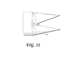
図7〜図12は、実施形態による、閉じた位置から途中まで開いた位置、また完全に開いたコアリング及び/又は送達位置に及ぶ種々の連続的な段階、並びに、完全に開いた位置から途中まで閉じた位置、また完全に閉じた部分切断及び/又は閉じた穿通位置に進む次の段階における図1のコア生検装置の嘴を示している。実際には、図7〜図12は、実施形態による、図1のコアリング生検装置の構成部材の動作及び機能の種々のフェーズを示している。具体的には、図7は、閉形態における筒状のコアリング・輸送アセンブリ11及び取り付けられている嘴状アセンブリ13の切り取り要素の回転及び前方又は遠位への軸方向移動のフェーズ、並びに、筒状のコアリング・輸送アセンブリ11の内部の筒状要素/螺旋状要素26の突出要素(単数または複数)71に接続されている付加的なヒンジアセンブリ(単数または複数)70の側面図を示している。図8は、組織標本(図示せず)を前方に/螺旋状に外方にコアリングし、及び/又は物質(図示せず)を組織内に送達するように開くときの、嘴状アセンブリ13の部分的に開いた回転及び軸方向前方にシフトする切り取り要素の側面図である。図8に示されているのは、嘴状アセンブリ13の要素、ヒンジアセンブリ50、筒状のコアリング・輸送アセンブリ11の非回転又は差動回転外側筒状要素25、並びに、筒状のコアリング・輸送アセンブリ11の内部の回転する筒状及び/又は螺旋状送達構成部材26の遠位に突出する要素71間の相互作用の詳細であり、遠位に突出する要素71は、筒状のコアリング・輸送アセンブリ11の内部構成部材26の突出要素71に接触する点に対して変化する外側筒状要素25に接触するヒンジアセンブリの面に起因して嘴状アセンブリ13を開くように働く。図9は、筒状のコアリング・輸送アセンブリ11及び切り取り用嘴13の広く開いたフェーズを示しており、嘴状アセンブリ13の切り取り要素を作動するように変化するヒンジアセンブリ70及び50の面72を更に示している。切り取り要素の回転及び軸方向移動は、図10、図11及び図12に示されているように、これら及び次に示すフェーズにわたって続くことに留意されたい。
FIGS. 7-12 illustrate various successive stages ranging from a closed position to an intermediate open position, and a fully open coring and / or delivery position, as well as from a fully open position, according to an embodiment. 2 shows the core biopsy device of FIG. 1 in the next stage, proceeding to a partially closed position and to a fully closed partial cutting and / or closed penetration position. In practice, FIGS. 7-12 illustrate various phases of operation and function of the components of the coring biopsy device of FIG. 1, according to embodiments. Specifically, FIG. 7 illustrates the phase of rotation and forward or distal axial movement of the cutting element of the cylindrical coring and
図10、図11及び図12は、広く開いたコアリング/送達フェーズ(図10)、それに順に続く、嘴状アセンブリ13の、これらの要素及び筒状のコアリング・輸送アセンブリ11の構成部材の回転及び軸方向移動中の螺旋状の閉じる移動を示している。図12は、1つの実施形態に従った、筒状のコアリング・輸送アセンブリ11の切り取り・部分切断用嘴状要素13による、コア組織標本(図示せず)の、その宿主組織との基部接続点からの完全な切除につがなる位置を示している。
10, 11 and 12 show the elements of the saddle-
図13、図14及び図15は、更なる実施形態による、嘴状アセンブリ13の切り取り要素を作動するための、嘴状アセンブリ13の切り取り要素と筒状のコアリング・輸送アセンブリ11の他の構成部材との間の相互作用に関する種々のヒンジアセンブリの代替的な細部を示している。図13は、ヒンジアセンブリ(単数又は複数)50がヒンジアセンブリ70に対する前方への回動及び移動中に内方に変位する実施形態を示している。この実施形態では、回転する螺旋状輸送要素26を用いてヒンジアセンブリ50を移動させることができ、一方で、外側の非回転又は差動回転外側筒状要素25との間の径方向位置に配置される付加的な回転する内部構成部材(図示せず)を用いてヒンジアセンブリ(単数または複数)70を固定することができる。図14は、切り取り用嘴状アセンブリ13のヒンジアセンブリ(単数または複数)50が外側の非回転又は差動回転外側筒状要素25によって平面内に固定されている別の実施形態を示しており、一方で、ヒンジアセンブリ(単数または複数)70は遠位に突出して開き、次に、近位に後退して戻って嘴状アセンブリ13の切り取り要素を閉じ、嘴状アセンブリ13の切り取り要素は、外方に遠位軸方向に移動して開きながら回転するように構成することができ、また、軸方向回転運動下で内方に移動して閉じる。そのような移動は、本発明の生検装置の動作のサイクル全体の特定のフェーズに応じて遠位及び/又は近位のいずれかに方向付けることができる。有利には、図14に示されているようにヒンジアセンブリ50を位置付けることによって、嘴状アセンブリ13の切り取り要素の外径を正確に制御可能とし、確実に位置付けることが可能となる。そのようなヒンジアセンブリ50は、嘴状アセンブリ13の切り取り要素が、より近位のコアリング/輸送用外側筒状要素25の外径を越えないことを可能にする(それ以上越えないことが望ましい)。また、嘴状アセンブリ13の切り取り要素は、切り取り要素が十分に内方にヒンジ移動し、各コアリングサイクルの終わりにおいて閉塞するとともに、コアサンプルを部分切断/切除することを可能にするように構成することができる。図14は、筒状のコアリング・輸送アセンブリ11の外側の非回転又は差動回転外側筒状要素25内の筒状のコアリング・輸送アセンブリ11の内部の螺旋状の輸送コアリング要素26を含む実施形態も示している。この螺旋状要素26は、図1の生検装置の回転する切り取り用嘴状アセンブリ13のヒンジアセンブリ70を固定するものとして働く突出要素(単数または複数)71に取り付けることができるカラーセクション80において終端するように構成することができる。ヒンジアセンブリ50に対するヒンジアセンブリ70の平面の差動運動の結果、コアリング/生検サイクルの各段階において求められる機能が満たされるように、正しい正確なタイミングで切り取り用嘴状アセンブリ13が開閉する。
FIGS. 13, 14 and 15 show other configurations of the
図15は、位置付けリム81として働くことができる、筒状のコアリング・輸送アセンブリ11の外側の非回転又は差動回転外側筒状要素25の広がったテーパ状の表面81の例等の細部を示しており、位置付けリム81によって、外側筒状要素25及び切り取り用嘴状アセンブリ13のヒンジアセンブリ(単数または複数)50がヒンジ部品(単数または複数)70に対して軸方向に一緒に移動すると、ヒンジアセンブリ50が作動される。
FIG. 15 shows details such as an example of a non-rotating or differential rotating outer
図16は、閉じた位置にある1つの切り取り用嘴状要素13を含む1つの実施形態を示しており、一方で、付加的な切り取り用嘴状要素13aが、ヒンジアセンブリ50及び70の相対位置を示すように広く開いた位置において示されている。この図では、ヒンジアセンブリ(単数または複数)70の更なる細部が示されており、軸方向及び径方向の位置は、筒状のコアリング・輸送アセンブリ11の螺旋状のコアリング/輸送要素26の内側前方カラーセクション80内のスロット要素90、又は谷形状等の何らかの他の形状によって十分に制限される。これらの要素は、嘴状アセンブリ13を回転させ、また、ヒンジアセンブリ70をヒンジアセンブリ(単数または複数)50に対して軸方向に遠位及び近位に移動させ、前述した種々のフェーズにおける切り取り用嘴状アセンブリ13の開閉を作動するように一緒に作用する。
FIG. 16 illustrates one embodiment that includes one
図17、図18及び図19は、また更なる実施形態による、内部のコアリング/輸送用螺旋状筒状輸送アセンブリ102の付加的な切り取り用筒状構成部材101の前方切り取り縁を有する構成を示している。この場合、切り取り用嘴状アセンブリ13の作用を、この付加的な切り取り輸送アセンブリ102によって支持及び強化することができる。この構成では、切り取り用嘴13は、それらの遠位点においてよりしっかりと支持されることができ、付加的な前方縁が鋭利な表面103(遠位縁)、回転し遠位に移動する構成部材101によってコアリングを補助されることができる。この図では、回転する切り取り用嘴状アセンブリ13の側縁を保護するように支承表面リム104を設けることができる。
FIGS. 17, 18 and 19 show a configuration with a front cutting edge of the additional cutting
図20、図21及び図22は、また別の実施形態による、反対側の固定された(蝶着されていない)回転する切り取り用嘴状要素13bを有する、単一の蝶着されている回転する切り取り用嘴状要素13を有する代替的な構成の種々の斜視図を示している。図23a及び図23bは、図20〜図22に示されている単一の蝶着されている回転する切り取り用嘴13a及び固定されたヒンジ回転切り取り用嘴13bの側面図である。1つの実施形態によると、蝶着されている切り取り用嘴13aは、(図14のヒンジアセンブリ50と同様の位置にある)ヒンジアセンブリ106において摺動位置決めヒンジタブ105が取り付けられて示されている。この摺動位置決めヒンジタブ105の目的は、内部のコアリング/輸送用外側筒状要素25を内部の螺旋状コアリング/輸送構成部材26とともに回転させ、さらに、閉じた嘴を穿通させるために切り取り用嘴状要素13bを切り取り用嘴13aに向かって内方に閉じるよう軸方向移動を可能にし、コアリング段階の終わりにおいてコアサンプルをその基部の付着点において部分切断又は切除することである。図示のように、摺動位置決めヒンジタブ105を軸方向に作動することによって、アクチュエータ棒130が、摺動位置決めヒンジタブ105に接続することができる摺動リッジ/リム107と相互作用する。作動棒130が軸方向に遠位及び近位に移動すると、その力を、クレビス108を介して、外側筒状要素25のスロットを通して、リッジ/リム107に伝達することができ、これが更に、摺動位置決めヒンジタブ105を対応する距離及び方向に移動させる。この作用は、コアサンプルを宿主組織とのその基部接続部において穿通及び/又は部分切断するようにコアリング・輸送アセンブリ11の端を閉じるために、回転する嘴13bを、蝶着されていない回転嘴13a上のその他方のヒンジピボット109を中心に移動させ、その側部及び前方切り取り縁に沿って回転嘴13aに合わせる(閉じる)。また、嘴先端部53を、互いに隣接する閉じた位置において当接することによって切り取り動作で一緒に働く(回転時のハサミ動作)か、それらの先端部においてのみ合流するか、又は、他の隣接する嘴の縁がそれらの境界全体に沿って完全に接するか否かにかかわらず、輸送のために収集される組織標本の確実な部分切断を確かなものにするよう、「過蓋咬合」形態、「反対咬合」形態、若しくは他の形態をとるように構成することができる。
20, 21 and 22 show a single hinged rotation with opposite fixed (non-hinged) rotating scissor-
ここで、回転する切り取り用嘴の作動機構を参照する。図24は、1つの実施形態による、駆動モータ/クラッチアセンブリ29、一組のギヤ及びクランク/連接棒アセンブリ110、111、並びに、筒状のコアリング・輸送アセンブリ11の外側筒状要素25及び輸送要素26(螺旋状)及び27(マガジン)とのそれらの関係を示している。これらのアセンブリは、外側筒状要素25及び輸送要素26を回転及び軸方向移動で順次連続的に作動するように構成することができる。図24に示されているように、摺動/リング及び/又はギア構成部材116を介して内部の非回転又は差動回転螺旋状筒状構成部材26に関連するとともに作用する大きなギア及び連接棒アセンブリ110及び111、並びに、同様の摺動/リング又はギアアセンブリ117を介して非回転又は差動回転外側筒状要素25に関連するとともに作用する同様のアセンブリ110及び111を設けることができる。1つの実施形態では、ギア及び連接棒クランクタイプアセンブリ110及び111は、筒状のコアリング・輸送アセンブリ11の構成部材である外側筒状要素25及び輸送要素26自体を互いに対して移動させるように構成することができ、それによって更に、外側筒状要素25及び輸送要素26は、生検装置10の長軸に沿って図1の切り取り用嘴状アセンブリ13に個々に作用し、切り取り用嘴アセンブリ13を回転させながら開閉させることで、切り取り用嘴アセンブリ13は、コアリングのために組織内で広く開き、次に、コアリングサイクルの終わりにおいて互いに対して閉じるように戻ってコアサンプルの基部の付着部を切除することが可能であるものとすることができる。例示のために、筒状の非回転又は差動回転外側筒状要素25、内部の螺旋状の非回転又は差動回転コアリング/輸送要素26、及び切り取り用嘴状アセンブリ13を含む、図14に示されているような個々の構成部材に再び言及することが有益である。図24に更に示されているように、駆動モータ/クラッチアセンブリ29は、図示のようなウォームギア及びベベルギアの組又は何らかの他の機能的に同等のアセンブリ(単数又は複数)によって、歯車アセンブリ112を介して外側筒状要素25及び輸送要素26の一方又は双方に連結され、したがって、双方の回転の一致した速度又は異なる速度、及び嘴の穿通/開閉を所望に応じて達成することができる。図24のこの実施形態に示されているような、図14の要素25、26及び13も参照するそのような機構の目的は、外側筒状要素25及び輸送要素26の一方又は双方を同じ方向又は反対方向に回転させ、これによって次に、コアリングの種々のフェーズ中に切り取り用嘴状アセンブリ13も回転させ、コアサンプル(図示せず)を部分切断/切除し、コアサンプルを、筒状のコアリング・輸送アセンブリ11、外側筒状要素25及び輸送要素26、並びに/又は生検装置10の要素26及び27の接合部119のマガジン要素27を介し、ハンドル12を通して、図3に示されているような保管マガジン27内に近位に輸送し戻すためであるものとすることができる。ギアアセンブリ112のウォームギア要素は、異なるピッチ(図示せず)を有する2つの部分、例えば、摺動/リング構成部材116に関連するピッチ(116a)と、ウォームギアのその対応する部分117aに一致する摺動/リング/又はギア構成部材117自体のギアピッチの相対的に異なるピッチ、に分けることができる。そのような構成は、内部要素26の回転速度に対して外側要素25を差動回転させる1つの手段を提供する。図24に示されている更なる図は、真空/送達機構(さらに、以下で説明する図30の指定された要素140)に言及するものであり、これは、シリンジタイプの構成部材113、並びに、1つ又は複数のギア又は他の機構(図示せず)への関連するクランク/連接棒取り付け部114を含むことができ、コアリング及び輸送を補助することができる陽圧及び/又は真空を形成するようにプランジャアセンブリ115を前後に駆動する。真空/送達構成部材113は、図2に示されているような保管マガジン27内へのコア標本の移動を強化するために、例えば、チューブ及び弁アセンブリ(図示せず)を介して、図2に示されているような保管マガジン27に連結することができる。さらに、真空/送達構成部材は、構成部材(図示せず)を、筒状のコアリング・輸送アセンブリ11を介して生検部位に送達するように用いることもできる。真空/送達構成部材は、後述するように、図39に示されているような収集及び後の細胞学的分析のために、標的部位(病変又は他の部位)から流体及び遊離した組織細胞を引き出すように用いることもできる。
Here, reference is made to the operating mechanism of the rotating cutting rod. FIG. 24 illustrates a drive motor /
最後に、図24では、図24に参照符号118で示されているようなラックアンドピニオンアセンブリを設けることができる。このラックアンドピニオン機構は、キャリッジ又はサブステージ構造(ここでは図示せず)を、1つのユニットとして、ハンドル12内でハンドル12に対して前後に(近位及び/又は遠位に)移動させるように構成することができる。この(図1のハンドル12に対して)内部のサブ構造は、駆動モータアセンブリ29、並びに歯車アセンブリ112、筒状のコアリング・輸送アセンブリ11の筒状要素25及び輸送要素26、並びに取り付けられている切り取り用嘴状アセンブリ13、並びに1つの実施形態では、真空/送達構成部材113及び114並びに組織標本保管マガジン要素(単数または複数)27を含む構成部材のアセンブリを1つのユニットとして含むことができる。そのような移動の効果は、コアリング/部分切断フェーズ中に、生検装置10のコアリング構成部材の軸方向可動域である距離116a、117a(実際には比例しない)等を短くするか又は長くし、したがって、得られるコアサンプルを短くするか又は長くすることであり、このことは更に、採取される連続的なサンプルと、処置のビデオ撮影及び部位から採取される連続的なサンプルの書面による記録とのより高い関連付けにつながることができる。この機構自体は、操作者が回転を用いて又は回転させることなく短い段階で閉じた嘴の形態又は開いた嘴の形態のいずれかで組織に穿通することを望む、この装置の単純な繰り返し穿通モード機能としても用いることができる。そのような使用は、例えば装置が定位テーブルに堅くロックされている場合に、標的組織部位への、ゆっくりとしたすなわち熟考した上での精密な段階的な組織の穿通を可能にする。この機構には、ユーザ制御される電力、機械的な又は手動の(指/親指の摺動レバー等の操作者の力)が挙げられるがこれらに限定されない任意の手段によって動力を供給することができる。電気的に動力が供給される場合、選択可能な可動域の提供を行うことができる(機構は図示せず)。同様に図24に示されているのは、内部の螺旋状コアリング/輸送要素26と外側筒状要素25との間の、及び保管マガジン27の部分との(保管マガジン27の遠位部分は領域120によって表される要素26及び進入要素25にわたって摺動する)119における入れ子関係である。この構成は、領域120に沿う真空密な接続を提供するように構成することができるため、構成部材113及び114等の真空/送達構成部材によって真空及び/又は送達を達成することができる。
Finally, in FIG. 24, a rack and pinion assembly can be provided as indicated by
図25、図26及び図27は、更なる実施形態による、コアリング生検シーケンスの段階又は生検処置全体のコアリングフェーズにわたる、本発明の生検装置10の連続的な移動の段階を示している。しかし、これらの連続的な移動は、操作者の所望に応じて、生検装置10を1つの段階又は別の段階において停止させるように操作者によって中断することができる。中断の理由は、図2のより線維性の乳房組織16及び/若しくは標的病変15において生じ得るような困難な組織に穿通するために、又は、サンプルを収集し続けるが異なる角度で収集し続けるために、又は、サイクルの開始時に最初に想定していたよりも長い標本を収集するために、閉じた嘴の形態を延長することを含み得る。図24の110及び111等のギア及び連接棒は、図16の25等の構成部材及び輸送要素26の軸方向移動によって切り取り用嘴状アセンブリ13を移動させて正しい時点で開閉し、種々のコアリング/部分切断及び他の段階を達成するように、(図16に示されているような)コアリング/輸送チューブ要素25及び輸送要素26に個々に、順次に、連続的及び/又は断続的に作用するように構成することができる。
FIGS. 25, 26 and 27 show the stages of continuous movement of the
図25は、図2に示されているような標的病変15に近づくときの、乳房組織16等の器官の組織への閉じた嘴の穿通に適切な、1つのそのような段階(段階1)を示している。図25は、例示のために、図24の110及び111等のギア及び連接棒を、図24のギア110に関しては121及び122と表記される個々の構成部材に、並びに図24の連接棒111に関しては連接棒120及び123に分割する。図25に更に示されているように、連接棒120はギア121によって駆動することができる。連接棒120は、図24の摺動/リング/ギアアセンブリ117等によって図24の筒状要素25に連結することができる。要素122は例えばギア又はディスクであるものとすることができる。いずれの場合も、ギア122は、ギア121と同様であるものとすることができ、双方のギア121及びギア122に連結される単一の軸(図示せず)等によってギア121に連結することができる。ギア122には、この場合も連接棒120と同様であるものとすることができる連接棒123を連結することができる。一方で、連接棒123は、摺動リング機構116によって図24の内部の螺旋状筒状要素26に連結することができる。この装置の1つの実施形態の例示のために、図25の連接棒120又は123のいずれかを、ギア要素110(表記せず)から、真空アセンブリのプランジャ115を作動する図24のアクチュエータ棒114への連接棒の延長部によって示唆されるように、図23a、図23b又は図28の棒130に更に接続することができ、延長部は、この装置の1つの実施形態では、図24の外側要素25に遠位に(表記せず)沿い、最終的には図28の棒130になる。
FIG. 25 shows one such stage (stage 1) suitable for penetrating a closed fold into tissue of an organ, such as
記したように、ギア121及び122は、(互いに重ね合わせられるかのように)一緒に強固に連結することができる。しかし、連接棒120及び123の、ギア121及び122それぞれに沿う径方向位置は、ギア121及び122が互いに強固に接続されて回転すると連接棒120及び123の位置間にリードラグ関係が生じるように、意図的に異なって位置付けることができる。図25は、連接棒120及び121を、図5に示されているような切り取り用嘴状アセンブリ13に連結することができる図24の筒状要素25及び輸送要素26にそれぞれ取り付ける結果として閉じた嘴状アセンブリ13の形態になる連接棒120及び123間の関係を示している。この段階では、ギア122の周りの連接棒123に遅れをとるギア121に関連付けられる連接棒120(便宜上、双方のギアは反時計回りに回転すると仮定する)は、ハンドル12及び連接棒123に対してより遠位に配置することができる。この関係の結果として、切り取り用嘴状アセンブリ13が閉じた位置になる。図25に示されている段階は、コアサンプルをその基部において部分切断又は切除するのに有用であり、中断される場合は、筒状のコアリング・輸送アセンブリ11の閉じた嘴状アセンブリ13の回転、及び、図2に示されているように乳房組織16を通って標的病変15に近づくときの生検装置10による穿通にも有用な段階である。
As noted, the
図26は、順番的に図25に示されている段階に対して次の段階(段階2)を示している。この段階は、ギア122の周りを移動する連接棒123自体が連接棒120に対してより遠位に位置決めすると開始する。この関係の結果、切り取り用嘴状アセンブリ13が広く開いた形態に開き、これは、コアリング、及び/又は例えばマーカ若しくは治療薬の部位への送達に有利であり得る。双方の連接棒120及び123は、この段階中には遠位に前進することに留意されたい。しかし、連接棒120は連接棒123に遅れをとるため、連接棒120は、この段階の間中、連接棒123よりも近位に配置される。
FIG. 26 shows the next stage (stage 2) sequentially from the stage shown in FIG. This phase begins when the connecting
図27は、連接棒120がその最も遠位の位置に達すると、連接棒123が既に段階1におけるその位置に向かって近位に戻るその行程にある、順番的に次の段階(段階3)を示している。連接棒120に対する連接棒123のより近位の位置の結果として、切り取り用嘴状アセンブリ13が閉じ、連接棒120及び123が再び(図25に示されている)段階1に近づくにつれて互いにそれらの相対位置を変えるまで閉じたままである。ギア121及び122に取り付けられている連接棒120及び123に作用することができるディスクの形状(ギアは円形であるものとすることもできるが、連接棒120及び123に取り付けられているディスクは他の形状であるものとすることができる)は、種々の段階において経過する時間、並びに連接棒120及び123間の関係を変化させるように、楕円形(図示せず)等の円形以外の形状であることが理解される。
FIG. 27 shows in sequence the next stage (stage 3), when the connecting
図28は、1つの実施形態による、図24の内部の螺旋状コアリング/輸送要素26が作用する領域と同じヒンジアセンブリの領域(単数または複数)70(図7)に作用するように設計されている付加的な棒要素(単数または複数)130を含む側面図を示している。棒要素130は、図24の内部の螺旋状コアリング/輸送要素26の切り取り用嘴状アセンブリ13又は図25の棒120に対する軸方向の作用を強化する(高める)か又は取って代わるように構成することができ、これは、要素130等の中実の棒から得られる正確さが、図24の構成部材26等の螺旋状構成部材によって得られるものと比較してよりロバストかつ正確であり得るためである。そのような実施形態によると、棒要素130は、本発明の図28の切り取り用嘴状アセンブリ13の、図7のヒンジアセンブリ(単数または複数)70を移動させるために、図24の内部の螺旋状コアリング/輸送要素26に作用する図示の方法及び機構と同様であり得る方法で及び機構によって作動することができる。図28はまた、閉じた位置にある切り取り用嘴状アセンブリ13の近位部分131の最も近位の位置を点線によって示している。棒要素(単数または複数)130は、図24の摺動/リング要素116及び117等のハンドル内に示されているような同様の摺動/リング構成(図28には示さず)を介して、切り取り用嘴状アセンブリの軸方向運動を制御することができる。図29は、図28に示されているような棒要素130を含む、同じ要素を示す斜視図である。また、これらの制御棒が内部の螺旋状要素の外側にあるが外側筒状要素の内側にある場合、螺旋状要素が、外側筒状要素とともに異なる速度で又は異なる方向に回転する、棒に沿って摺動する組織とともに回転する作用によって、得られる組織標本の輸送を補助することができることを理解されたい。外側筒状要素が円形とは異なる断面形状を有し、例えば正方形である場合、制御棒は、外側筒状要素の長さに沿って内側角部内に入れ子状になることができることも可能である。図30は、1つの実施形態による生検装置10の側面図である。真空/送達アセンブリ140の同時の移動を示すために図1及び図2のコアリング/輸送構成部材11と平行な真空強化アセンブリ140が留意され、それらの構成部材11は結果として、コアリング、及び保管マガジン27内への生検標本(図示せず)の輸送を高めることができる。
FIG. 28 is designed to act on the same region (s) 70 (FIG. 7) of the hinge assembly as the region on which the inner spiral coring /
図31は、実施形態による、真空/輸送構成部材の連続的なサイクルがこれらの構成部材の起動中に可能であるように真空/送達アセンブリ140を駆動するベルトプーリー機構141を示す、図30の生検装置10の上面図である。図31はまた、真空/送達アセンブリ140と保管マガジン27との間の接続部(単数または複数)142の付加的な構造を示している。保管マガジン27は、図2の筒状のコアリング・輸送アセンブリ11の、図24の構成部材26と同様であるとともに構成部材26から延びる内部の螺旋状輸送構成部材(図示せず)を有することができる。保管マガジン27は、その長さに沿って穿孔又は開口143を有することもでき、これらはそれぞれ、例えば組織サンプル(図示せず)を順次収集及び/若しくは空にし、かつ/又は乳房組織16等の器官内に、マーカインプラント、トレーサ要素、前処理、処置間処理及び/若しくは後処理用の薬剤等の特定の物質(図示せず)を送達/堆積させるよう、組織標本(図示せず)の物質取り扱いのために真空及び/又は陽圧を均一に及び/又は徐々に分散させる目的で、寸法が任意選択的に変化するか、及び/又は徐々に変化する。図31はまた、装置10において(例えば螺旋状のコアリング/輸送要素26の内部に沿って)長手方向内腔を一時的に占めることができるか、又は、生検装置10の中央コアに対して平行な線に沿って位置決めされる(この位置は示されていない)バレル及び/若しくはループ又は一連のループ等において生検装置10の中央コアに隣接して配置することができる、移動可能な又は固定されるガイドワイヤ又は針等の任意選択的なガイド要素144の部分セグメントを示している。ガイド要素144は、例えば、生検装置10の筒状のコアリング・輸送アセンブリ11の経路に沿って方向付けられるレーザ光、又は、針若しくはワイヤ等の中実材料ではない(又は中実材料に加えて)他の視覚をガイドする補助具を含むことができる。筒状のコアリング・輸送要素は、屈曲可能であるように構成される場合、堅く湾曲し、例えば標的組織までの指図された経路を辿るように予め位置決めすることができる針又はワイヤ等を辿ることができる。要素144は、(鋭利な先端部を有する針ではなく)単純な中空のチューブであってもよく、このチューブは、様々なデュロメータのプラスチック材料若しくは金属材料に連結される、堅いか、可撓性であるか若しくは部分的に可撓性であるプラスチック材料等であるものとすることができ、傷付けない先端部を有することができ、この要素にわたって装置を導入する前に病変に配置することができ、又は代替的には、例えば生検器具の取り出し時に部位への継続的なアクセスを可能にするために後の段階で装置内に配置することができる。このアクセスの目的は、薬剤、小線源療法又は他の移植可能なアイテムを(一時的若しくは恒久的に)後で又は後日に送達するためであるものとすることができ、より嵩張る生検器具が取り出される時点のずいぶん後でもそのようなアクセスを続けることができるという利点がある。そのような要素は、例えば後の一回の使用又は繰り返しの使用のために滅菌包帯下で適所に固定することができる。要素140及び27は、例えば保管容量が最大限まで満たされ得ると、又は以下で示す(例えば図39のカートリッジ214)のような送達カートリッジ(図示せず)に切り換えるために、所望に応じて取り外し可能及び/又は交換可能であるものとすることができる。
FIG. 31 shows the
図32は、1つの実施形態による、非回転(例えば)外側チューブ25によって覆われる、図24の内部の螺旋状コアリング/輸送要素26を回転させるギア駆動機構150の側面図を示している。25bは、例えば外側チューブが円形の断面を有する場合に外側チューブを装置のハウジングにロックする働きをする突出するキー型の要素を示している。図示のように、作動棒(単数または複数)130(図28)は、切り取り用嘴状アセンブリ13を移動させるためにコアリング/輸送要素26とともに前方に(遠位に)及び後方に(近位に)同様に駆動されるチューブ25内に収容することができる。作動棒(単数または複数)130は、例えば、嘴状アセンブリ13が「十分であるよりも開いた」又は中心を越えた(すなわち、外側棒(単数または複数)130を有するチューブ25の外径よりも大きい直径の組織をコアリングする切り取り先端部)形態にある状態で、チューブ25の外側に配置することもでき、外側棒(単数または複数)130が、軸方向に穿通される組織に結合することなくチューブ25とともに回転することを可能にする。組織保管マガジン27(図31)の取り付けセグメントも示されている。
FIG. 32 illustrates a side view of a
図33、図34及び図35は、更なる実施形態による、外側の非回転又は差動回転外側筒状要素25を伴った、非回転又は差動回転内部螺旋状コアリング/輸送要素26等の要素の「バレルを下から見た」斜視図である。これらの図は、施条内側処理部160(ランド、ピット、溝、隆起した若しくは窪んだ特徴部等)、又は外側筒状要素25の内面の他の物理的処理部の様々な構成を示している。表面処理部160等の処理部は、外側筒状要素25又は内部の螺旋状コアリング/輸送要素26いずれかの回転によってコア組織標本(単数または複数)が軸方向に移動するように、コア組織標本(単数または複数)の捩れに抵抗するように構成することができる。図示のような内側処理部160は、1つの実施形態によると、外側のコアリング/輸送用筒状要素25の内壁に切り込まれる施条溝として構成することができるか、又は、筒状要素25の内壁の周りに配置される構造リブであるものとすることができる。付加的に、又は施条溝若しくは他の特徴部の代わりに、筒状要素25の内面内に、幾何学的に好ましく(連続的に若しくは不連続的に)内側粗面を形成すること、又は、任意の別の方法で内部の螺旋状構成部材26に対して摩擦がより高い内面を形成することによって、標的病変15等から組織標本(単数または複数)を同様に所望通りに長手方向に移動させ、そのような切除された組織コアをコアリング/輸送要素25内で近位方向に付勢することができる。図34及び図35は、更なる実施形態による、外側筒状要素25の内壁の特徴部の他の可能性のある施条処置部160の構成を示している。記載したように、要素25若しくは26のいずれかの回転、又はこれらの要素の差動回転によって、組織の特性及び他の要因に部分的に依存して、最適な移動の力が生じる。最適な構成は、これらの機構によって輸送される種々のタイプの物質に関して実験的に決定することができることを理解されたい。
FIGS. 33, 34 and 35 illustrate a non-rotating or differential rotating inner helical coring /
図36は、より内部の螺旋状構成部材26に対して異なるピッチ角度(単数または複数)を有する付加的な内部の螺旋体(単数又は複数)170が設けられているまた別の実施形態を示している。この実施形態では、螺旋状要素(単数または複数)170は、内面構成部材及び/若しくは表面処理部160等の表面処理部、又はコアリング/輸送チューブ要素25と一体的であるか若しくは強固に取り付けることができる他のものに加えて、又は代わりに設けることができる。様々な速度若しくは方向を用いること、又は一方若しくは他方の螺旋状構成部材を回転しないように固定することは、標的病変15等から内部の(例えば組織)物質を長手方向又は軸方向に(例えば近位の向きに)移動させる例示的な動作である。さらに、この図は、同じ速度で及び同じ方向に回転されると組織の穿通を補助する鋭利な先端部又は先端縁が連結される、同時に作用するか、又は異なる回転速度で及び/若しくは異なる回転方向に作用する付加的な螺旋状要素(単数又は複数)の使用の可能性を示している。
FIG. 36 shows yet another embodiment in which additional internal helical (s) 170 having different pitch angle (s) 170 relative to the more internal
図37は、生検装置10の3つの図を示しており、図37の上部及び底部は側面図であり、その中央の図は見下ろした平面図であり、実施形態の更なる態様を示している。この図では、内部キャリッジ構造180が、筒状のコアリング・輸送アセンブリ11、ハンドル12及びその固定された起動スイッチ(図示せず)に対して移動可能であるものとすることができる、作動、コアリング、輸送及び保管/送達のために必要な及び/又は付加される全ての要素(これらに限定されない)を伴った切り取り用嘴状アセンブリ13、並びに、ハンドル12への電源及び配線取り付け部(図示せず)を含む、担持される構成部材とともに示されている。この実施形態では、真空/送達アセンブリ140は、キャリッジ180によって移動されるのではなく固定することができる。キャリッジ180を移動させる機構のうちの1つは、より長いか若しくはより短いコア標本の長さ部分182、183のいずれかを所望に応じて回収することができるか、又は本発明の生検装置のコアリング要素による、大きな血管若しくは他の近傍の器官等の隣接する脆弱な構造内への不所望の穿通を防止するように、コアリング中に操作者がキャリッジ構造180を手動で移動させるのに用いることができる手動の摺動レバー要素181である。代替的には、キャリッジ180の作動は、モータを介して、又はキャリッジ180の可動域及び方向を含むキャリッジ180の移動のために、ラックアンドピニオン機構(図示せず)等の機械的に駆動される機構を介して行うことができる。これらの移動は、所望に応じて、容易に操作者が予め選択可能であるようにすることができるか、又はリアルタイムで(すなわちコアリング段階自体の間に)選択することができる。
FIG. 37 shows three views of the
図38は、1つの実施形態による、代替的なキャリッジ190を含めてキャリッジを含む、生検装置10の側面図及び上面図を示しており、キャリッジはこの場合、そのフレーム内に真空/送達アセンブリ140、141を含むことができ、それによって、キャリッジ190の移動は同様にそれらの軸方向の向きの可動域を変える。
FIG. 38 shows a side and top view of the
図39は、そのシールキャップ211が適所にあるとともに接続チューブ212が取り付けられていない収集レセプタクル210が設けられているとともに連結されている、実施形態による生検装置10の側面図である。収集チューブ212は、一方向弁213を適所に含むことができ、また、フィルタ弁216を交換することによって流体が真空/送達アセンブリ140によって吸引されることを可能にすることなく生検部位から収集された液体を収集レセプタクル210内に送達するように設計されている他の構造を含むことができる。この実施形態では、(図31に示されている)保管マガジン27の代わりに送達カートリッジ214が用いられており、それによって、真空/送達アセンブリ140を、カートリッジ214内に予め入れることができるカートリッジ214の内容物を送達するように位置決めすることができる。接続チューブ215は真空/送達アセンブリ140と送達カートリッジ214との間に接続して設けることができ、この接続チューブは、一方向フィルタ弁216を有して示されており、一方向弁213と比べて反対の機能方向に、横断される組織に又は生検部位において注入されることが望ましい物質を加えるために装置への送達ポートとして働き、またそれによって、例えば周囲空気(任意選択的に濾過される)を真空/送達アセンブリ140によって引き込み、真空/送達アセンブリ140が、送達カートリッジ214の内容物を生検キャビティ(図示せず)内又は生検領域付近の組織内に堆積させるようにコアリング・輸送アセンブリ11に送達することを可能にすることができる。
FIG. 39 is a side view of a
図40は、生検装置10に接続されている送達シリンジ220を含むことができる別の実施形態による生検装置10の側面図であり、それによって、プランジャ221を送達シリンジ220内に押下すると、その内容物を、生検キャビティ内若しくは生検キャビティ付近に、又はプレ生検の場合には標的病変付近の組織内に送達及び堆積させるようにコアリング・輸送アセンブリ11に送達することができる。この図では、筒状のコアリング・輸送アセンブリ11の回転方向を逆にすることによって、装置から(装置の端部から)例えば病変内の組織送達部位内又は乳房組織の近傍に遠位に送達が行われる。送達シリンジ220の内容物は、本質的に固体、半固体、液体及び/若しくはガス状、放射性、並びに/又はこれらの組み合わせであり得る前処理薬剤、作用物質又は他の送達可能物、審美を高める目的の不活性であり得る移植可能な要素、並びに、リファレンス目的及び他の目的のマーキング物質を含む種々の物質を含むことができる。これらのタイプの要素の全てが示されるわけではないが、223によって表される内部のマーカ要素を有する固体の又は海綿状の圧縮可能なタイプのペレット222が図40に描かれて示されている。
FIG. 40 is a side view of a
以下、実施形態による本発明の生検方法の態様を説明する。特に、以下では、閉じた及び開いた嘴状アセンブリの形態及び段階を、本発明の生検装置の設計、機能及び特徴によって可能となる特定の目的のために用いることができる方法を説明する。本明細書において説明するように、生検装置10は、患者の組織内で標的病変まで生検装置10の先端部を追跡するために、生検処置中の種々の時点において開いた嘴の形態及び/又は閉じた嘴の形態のいずれか又は双方で用いることができる。図7及び図23bに示されているような閉じた嘴状アセンブリの形態、又は図9及び図23bに示されているような開いた嘴状アセンブリの形態で標的につながる組織に穿通することが望ましいであろう特定の臨床的状況が存在する。図9及び図23bの閉じた嘴状アセンブリの形態の使用の臨床例は、超音波誘導の外乱を最低限に抑えることができるように標的病変15にゆっくりと近づくことを含むことができる。なお、閉じた嘴の形態では、標的病変15までのアクセス経路に沿って生検コアは生成されないか又は切り込まれないものとすることができる。図9及び図23の開いた嘴の形態で標的病変に近づくことができる別の状況で臨床的な必要性を満たすことができる。開いた嘴の形態は、生検装置10の操作者が例えば密な線維性の組織のコアを取り出すことを可能にし、処置の中断若しくは停止後のこの装置のその後の操作(例えば再挿入)の場合の容易な通過及び最低限の外傷、又は、関連するカテーテル、装置等が標的領域(単数または複数)まで形成された経路まで、また経路を通って通過することを可能にする。これらの2つの明らかに異なる形態を使用することを伴う方法は、回転する切り取り用嘴状アセンブリ13自体の設計、及び、生検装置10がその後の段階に向けて移動する前に段階を停止又は中断することができることによって可能となる。加えて、実施形態は、次の段階(単数または複数)への進行に伴い閉じた嘴の回転の切り離しを可能にする。この特徴は、(「中断した」段階の形態において動作しながら)連続的な輸送、及び、保管マガジン要素の長さと組み合わせたアセンブリ11の長さのみによって制限される連続的なコアリング/輸送を可能にし、それによって、臨床的に有用である場合に、数インチもの長さのコアを回収することができる。これが望ましいであろう臨床的状況は、組織内で、例えば乳房組織内の罹患乳管(図示せず)の経路に沿うといったように特定の構造を辿ることを含むことができる。
Hereinafter, the aspect of the biopsy method of the present invention according to the embodiment will be described. In particular, the following describes a method in which closed and open saddle assembly configurations and stages can be used for specific purposes enabled by the design, function, and features of the biopsy device of the present invention. As described herein, the
本発明の生検方法は、1つの実施形態によると、(乳房等の)器官の組織をイメージングすることができ、標的病変を特定することができる。既知の消毒技法を用いて皮膚表面を清潔にすることができる。次に、患者にドレープをかけることができ、(例えば局所)麻酔薬を必要に応じて投与することができる。その後、本発明の生検装置を、小さい切開部(例えば皮膚の切れ目)を通して導入することができる。次に、本発明の生検装置を、穿通モードにおいて、遠位の嘴13が閉じた嘴の形態又は開いた嘴の形態のいずれかにある状態で配置することができる。本発明の生検装置に閉じた嘴の形態をとらせる(ゼロを含む任意の所望の速度における回転のみの段階)場合、遠位の嘴13を次に、標的病変に向かって組織を通って前進させ、標的病変の最も近い縁のちょうど手前で(例えば2mm〜4mm)止めることができる。本発明の生検装置は、部分切断段階の前の任意の時点で閉じた嘴の形態又は開いた嘴の形態をとることができる。医師は次に、所望に応じて本発明の生検装置を前進させ続け、連続的にコアリングし、コアリング動作を開始及び停止し(回転/輸送)、先端部を方向付けし直し、並びに/又は先端部を方向付けし直しながらコアリング動作を続けることができる。コアリングは所望の長さの標本を形成し続けることができる。次に、部分切断段階を行うことができ、コアリング/輸送/部分切断サイクルを完了することができる。
The biopsy method of the present invention, according to one embodiment, can image organ tissues (such as the breast) and identify target lesions. The skin surface can be cleaned using known disinfection techniques. The patient can then be draped and an (e.g., local) anesthetic can be administered as needed. The biopsy device of the present invention can then be introduced through a small incision (eg, a skin cut). The biopsy device of the present invention can then be placed in the penetrating mode with the
生検サイクル全体の残りは、上述したように行うことができるが、本発明の生検装置は任意の時点で開いた嘴の形態及び閉じた嘴の形態をとることができることに留意されたい。上述した形態/モードは、所望の頻度及び/又は長さだけ中断又は維持することができる。例えば、そのようなモードは、例えば乳房の組織内の管に沿って見られ得るような異常組織成長の経路を辿るように(開いた嘴のコアリング/輸送モード)必要に応じて使用することができる。得られた情報は、開いた嘴の形態において、保管マガジン設計及びその使用目的に特有の自動的な記録及び保存機能を使用して、組織病理学検査によって分析される特定のコアサンプルが標的領域(単数または複数)内の特定のイメージングされる異常に一致することを更に関連付ける(またそのような関連付けをドキュメント化する)手段として用いることができる。 It should be noted that the remainder of the entire biopsy cycle can be performed as described above, but the biopsy device of the present invention can take the form of an open fold and a closed fold at any given time. The forms / modes described above can be interrupted or maintained for a desired frequency and / or length. For example, such a mode may be used as needed to follow the path of abnormal tissue growth (open coral / transport mode) as may be seen, for example, along a duct in the breast tissue Can do. The information obtained is that in the form of an open basket, a specific core sample that is analyzed by histopathology examination using a storage magazine design and automatic recording and storage functions specific to its intended use. It can be used as a means of further associating (and documenting such an association) matching a particular imaged anomaly within (s).
以下で説明するのは、本発明の生検装置のキャリッジの移動機能及び構造の実施形態を使用する方法である。キャリッジの構造及び機能は、手動で作動されるか又は動力を供給されるかにかかわらず、またコアリング段階中に「オンザフライ」で用いられるか又は予め設定されるかにかかわらず、本発明の生検装置の近傍の脆弱な構造内への不所望の遠位の穿通を防止するために使用することができる。本発明の生検装置の実施形態は、保管マガジン27(図3を参照のこと)の構造に特有の記録保持機能、並びにキャリッジ移動(単数または複数)の構造及び機能を別個に又は組み合わせて使用することによって別の重要な臨床的必要性を満たし、この場合はそれぞれがその特定のコアサンプルに固有であり得る可変の長さの収集されるコアを固有に更に特徴付ける。この特徴及び/又は特徴の組み合わせは、本発明の装置の操作者が、組織病理学者が対象とする特別な領域に「マークする」ことを可能にする。このマーキングは、例えば処置中の任意の時点(単数又は複数)において付加的なマーキングカートリッジを使用して色素等のマーカ要素を注入することによって本発明の生検装置により達成することもできる。 Described below is a method of using an embodiment of the carriage movement function and structure of the biopsy device of the present invention. The structure and function of the carriage, whether manually operated or powered, and whether used on-the-fly or preset during the coring phase, It can be used to prevent unwanted distal penetration into a fragile structure in the vicinity of the biopsy device. Embodiments of the biopsy device of the present invention use the record retention function specific to the structure of the storage magazine 27 (see FIG. 3) and the structure and function of carriage movement (s) separately or in combination. This fulfills another important clinical need, in which case it further uniquely characterizes the variable length collected cores, each of which may be unique to that particular core sample. This feature and / or combination of features allows the operator of the device of the present invention to “mark” a special area of interest to the histopathologist. This marking can also be achieved by the biopsy device of the present invention, for example by injecting a marker element such as a dye using an additional marking cartridge at any point (s) during the procedure.
実際には、1つの実施形態によると、生検方法は、(乳房等の)器官の組織をイメージングすること、及び標的病変を特定することを含むことができる。既知の消毒技法を用いて皮膚の表面を清潔にすることができる。次に、患者にドレープをかけることができ、次に、必要に応じて(例えば局所)麻酔薬を次いで送達することができる。次に、本発明の生検の遠位の嘴13を、小さい切開部(例えば皮膚の切れ目)を通して導入することができる。次に、閉じた嘴の形態又は開いた嘴の形態のいずれかで穿通モードを起動することができる。閉じた嘴の形態(回転のみの段階)を使用する場合、次に、遠位の先端嘴13を、標的病変に向かって前進させ、標的病変の最も近い縁のちょうど手前で(例えば2mm〜4mm)止めることができる。開嘴段階は任意の時点で開始し、部分切断段階の前に中断することができる。本発明の生検装置を、所望に応じて更に前進させ、連続的にコアリングし、コアリング動作を開始及び停止し(回転/輸送)、遠位の嘴13を方向付けし直し、及び/又は遠位の嘴13を方向付けし直しながらコアリング動作を続けることができる。コアリングは所望の長さの標本を形成し続けることができる。次に、部分切断段階を可能にすることができ、コアリング/輸送/部分切断サイクルを完了することができる。生検段階中に、キャリッジの移動を所望に応じて使用して、近傍の器官及び/若しくは組織への器具先端部の不所望の進入を防止し、並びに/又は、より長いコア標本(単数または複数)を取り出してより多くの異常組織を得るために、並びに/又は標的病変の近い縁若しくは遠い縁の正常な組織の要素を含めるように、可動域を安全に限定(例えば短くするか又は長くする)することができる。いずれか又は双方の場合(より長い/より短い標本コア)、キャリッジの移動を行いながら得た情報を使用して、固有の長さで収集された組織を更に特徴付ける(またそのような特徴付けをドキュメント化する)ことができ、それによって、保管マガジン設計及び使用目的に特有の自動的な記録及び保存機能を使用して、各標本の組織病理学的分析を標的病変内の特定のイメージングされる領域に確実に関連付けることが可能となる。
Indeed, according to one embodiment, the biopsy method may include imaging tissue of an organ (such as a breast) and identifying a target lesion. Known sterilization techniques can be used to clean the surface of the skin. The patient can then be draped and then an anesthetic can then be delivered as needed (eg, local). The biopsy
本発明の生検装置の操作者が、保管マガジン27(図3)の記録保存機能を損なうことなくコアサンプルをより詳しく、場合によっては触覚によって調べることを可能にすることによって、種々の臨床的必要性を満たすことができるように、保管マガジン27(図3に示されている)の使用の更なる態様をここで説明する。また更なる実施形態による、サンプルが保管/記録保存用保管マガジン27内に受け入れられて保管される順であるような、ex−vivoイメージングの更なる方法も説明する。実施形態による保管マガジンは、処置中の任意の時点(単数または複数)で取り外し可能及び/又は交換可能であるように構成することができるため、本発明の生検装置は、種々の処置方法を確実にすることを可能にし、これは、本明細書において開示される構造を用いずには可能ではないか、又は少なくとも実現が困難であろう。例えば、本発明の生検装置を用いて、臨床医は、1つの保管マガジンの内容物を別の付加的な保管マガジンの内容物から分離することができる。本発明の生検装置の操作者は、生検装置の別の機能によってコアリング/輸送/保管を中断することも可能であるものとすることができ、その間ずっと、操作者の裁量で、本発明の生検装置のシャフトのコアリング・輸送アセンブリ11を適所に保ち、したがって、本発明の生検装置のこれらの要素の繰り返しの取り出し及び挿入に関連する外傷を最低限に抑える。
By allowing the operator of the biopsy device of the present invention to examine the core sample in more detail, and possibly by touch, without compromising the record storage function of the storage magazine 27 (FIG. 3), In order to be able to meet the needs, further aspects of the use of the storage magazine 27 (shown in FIG. 3) will now be described. A further method of ex-vivo imaging is also described in which the samples are in the order in which they are received and stored in the storage /
実際に、1つの実施形態によると、組織生検方法は、上述したようなコアリング/生検/輸送サイクルを行うことを含むことができる。その後、保管マガジンを取り外し、並びに/又はマーキング及び/若しくは治療フェーズに進むことによって処置を完了することができる。次に、保管マガジンを取り外し、所望であれば、X線、磁気共鳴イメージング及び/若しくは超音波振動子、又は、保管マガジンが透明な材料から作製される場合には高解像度デジタルカメラ下に配置することができる。次に、コア組織標本をイメージング/記録することができる。次に、マガジンを送達レセプタクルに入れ、封止し、コア長を書き留めるとともにin−situ及びex−vivoで撮像記録(単数または複数)と関連付ける更なる分析のために研究室に送ることができる。保管マガジンを本発明の生検装置から取り外すと、次に、収集したコアを、マガジンの透明な壁を通して目視検査することができる。次に、マガジンを分割して開き、所望に応じて組織標本を触覚によって分析することができる。次に、マガジンを、内部の標本とともに再び閉じることができる。次に、マガジンを輸送レセプタクルに入れ、封止し、研究室に送ることができる。 Indeed, according to one embodiment, the tissue biopsy method can include performing a coring / biopsy / transport cycle as described above. The procedure can then be completed by removing the storage magazine and / or proceeding to the marking and / or treatment phase. The storage magazine is then removed and, if desired, placed under X-ray, magnetic resonance imaging and / or ultrasound transducers, or a high resolution digital camera if the storage magazine is made from a transparent material. be able to. The core tissue specimen can then be imaged / recorded. The magazine can then be placed in a delivery receptacle, sealed, and the core length can be noted and sent to the lab for further analysis associated with the imaging record (s) in-situ and ex-vivo. When the storage magazine is removed from the biopsy device of the present invention, the collected cores can then be visually inspected through the transparent wall of the magazine. The magazine can then be split open and the tissue specimen can be analyzed by touch as desired. The magazine can then be closed again with the specimen inside. The magazine can then be placed in a transport receptacle, sealed, and sent to the laboratory.
次に、保管マガジンを、必要に応じて付加的な空の保管マガジン(単数または複数)と交換し、生検処置を完了することができる。代替的には、他のカートリッジ/マガジンを本発明の生検装置に装着し、薬剤、マーカ及び/若しくはトレーサ要素、治療薬、又は治療用及び/若しくは審美用のインプラントを生検部位に送達することができる。次に、処置を終了するか、又は、施術者が臨床的に有用であるとみなされるような他の近傍の領域を生検/コアリングすることを望む場合等には継続することができる。 The storage magazine can then be replaced with additional empty storage magazine (s) as needed to complete the biopsy procedure. Alternatively, another cartridge / magazine is mounted on the biopsy device of the present invention to deliver a drug, marker and / or tracer element, therapeutic agent, or therapeutic and / or aesthetic implant to the biopsy site be able to. The procedure can then be terminated or continued, such as when the practitioner wishes to biopsy / coring other nearby areas as deemed clinically useful.
本発明の生検装置は、例えばステンレス鋼又は他の生体適合性合金等の1つ又は複数の生体適合性材料から形成するか又は生体適合性材料を含むことができ、機能(単数または複数)を最適化する必要に応じてポリマー及び/若しくは生体適合性材料から作製するか、ポリマー及び/若しくは生体適合性材料を含むか、又はポリマー及び/若しくは生体適合性材料でコーティングすることができる。例えば、(嘴状アセンブリ13の構成要素等の)切り取り要素は、硬化合金を含むか又は硬化合金から作製することができ、滑りやすい材料(単数又は複数)で付加的にコーティングし、それによって、種々の堅さ及び摩擦の生体組織内の通過を最適化することができる。構成部材の幾つかは、輸送用の筒状の保管構成部材を参照して本明細書において詳述したように、隣接する構成部材に対して意図的に異なって表面処理することができる。種々のギアは、ナイロン、成形用プラスチック等のポリマー及び他のものといった任意の好適な市販の材料から作製することができる。使用される場合、本発明の生検装置の種々の給電される機能に給電するモータは、市販の電気DCモータであるものとすることができる。本発明の生検装置のハンドルは同様に、安価な射出成形プラスチック、若しくは他の好適な剛性の、容易に手で保持される強固な軽量材料から作製するか又は含むことができる。ハンドルは、定位テーブルステージ等の任意の数の既存のガイドプラットフォームのうちの1つに容易に適合可能であるように構成することができる。本発明の生検装置において用いられる材料は、本発明の生検装置が生検処置に一般的に用いられる磁気共鳴イメージング(MRI)機器との適合性を維持するように、強磁性の観点から慎重に選択することもできる。真空/送達アセンブリの構成部材は、本発明の生検装置に接続する市販のシリンジ及び管を、真空構成部材によって吸引することができる流体等の材料の吸引と空にすることとの間で切り換える容易に入手可能なリード弁とともに含むことができる。本発明の生検装置の実施形態によってこのように収集される流体は、次に、廃棄するために、又は研究室の細胞分析用に安全に保存しておくために、付加的な外部の、但し持ち運び可能な、本発明の生検装置の管に接続される液体保管容器に排出することができる。 The biopsy device of the present invention can be formed from or include one or more biocompatible materials, such as, for example, stainless steel or other biocompatible alloys, and the function (s) Can be made from polymers and / or biocompatible materials, or can include or be coated with polymers and / or biocompatible materials as needed. For example, a cutting element (such as a component of the saddle-like assembly 13) can comprise or be made of a hardened alloy and additionally coated with a slippery material (s), thereby It is possible to optimize the passage of various stiffness and friction in living tissue. Some of the components can be intentionally surface treated differently relative to adjacent components, as detailed herein with reference to a cylindrical storage component for transport. The various gears can be made from any suitable commercially available material such as nylon, polymers such as molding plastics and others. When used, the motor that powers the various powered functions of the biopsy device of the present invention can be a commercially available electric DC motor. The handle of the biopsy device of the present invention can also be made from or include an inexpensive injection molded plastic, or other suitable rigid, strong, lightweight material that is easily held by hand. The handle can be configured to be easily adaptable to one of any number of existing guide platforms, such as a stereotactic table stage. The materials used in the biopsy device of the present invention are from a ferromagnetic point of view so that the biopsy device of the present invention maintains compatibility with magnetic resonance imaging (MRI) instruments commonly used for biopsy procedures. You can also choose carefully. The components of the vacuum / delivery assembly switch between commercially available syringes and tubes connected to the biopsy device of the present invention between the aspiration and emptying of materials such as fluid that can be aspirated by the vacuum components. It can be included with a readily available reed valve. The fluid thus collected by an embodiment of the biopsy device of the present invention is then added to an additional external, for disposal or for safe storage for laboratory cell analysis. However, it can be discharged into a portable liquid storage container connected to the tube of the biopsy device of the present invention.
電源は、医療装置用途に承認されているとともに本発明の生検装置に設けられているソケットに差し込まれる外部の市販のAC−DC変圧器を含むことができるか、又は、任意の好適な市販の電源の密閉型バッテリを含むことができる。バッテリは、一回使用で使い捨ての(任意選択的にリサイクル可能な)バッテリであるものとすることができるか、又は充電式バッテリであるものとすることができる。 The power source can include an external commercially available AC-DC transformer that is approved for medical device applications and plugged into a socket provided in the biopsy device of the present invention, or any suitable commercially available. It can include a sealed battery of the power source. The battery can be a single use, disposable (optionally recyclable) battery, or it can be a rechargeable battery.
生検装置の実施形態の切り取り用嘴状アセンブリは、標的病変に近づくときに組織を穿通するために、それらの形状、アタッチメントを変えることなく、又は任意の他の変更を伴うことなく使用することができる。次に、切り取り用嘴状アセンブリを用いて組織標本を開いてコアリングし、その後、コアリング段階の終わりに標本を部分切断することができる。嘴状アセンブリを用いて収集された標本の輸送を高めることを助けることもできる。そのような複数の機能が単一の装置に一体化されていることによって、貴重な断面積が節減され、これによって更に、最大径のコアサンプルを提供しながらも最小の外径を有する装置が形成される。コアサンプルの直径を最大にすることは、臨床的観点から重要であると考えられ、これは、同業者によって評論される複数の刊行物において、より大きい直径のコア標本ほどより正確な診断が下されると実証されているためである。しかし、臨床的に大径のコアサンプルが望まれることは、より大きい口径の装置に関連する外傷と比較考量しなければならない。実施形態は、臨床医が両者の長所を得ることができるようにその比率を最適化する。有利には、1つの実施形態によると、内部の螺旋状輸送システムは、前方切り取り用嘴のコアリング機能を高めるように構成することができる。螺旋状の輸送コアリング要素は、コアリング中及びコアリング後に、コアリングされた標本に対して緩やかな予測可能な牽引を与えるように構成することができ、これによって、本発明の生検装置のコアリング要素の長手方向可動域の理想的な速度と、同じ要素の回転運動の理想的な速度とを合わせることが可能となる。このように、収集される標本のアーキテクチャが輸送中に破壊される可能性が低くなる。同業者によって評論される科学論文において、組織のアーキテクチャを可能な限り保つこと(すなわち、組織のアーキテクチャをin vivoにあった状態で保つこと)は、より容易でより正確な診断につながることが示されている。本発明の真空/送達機構は、標本のコアリング及び輸送を可能な限り繊細に、但し確実に取り扱うように、コアリング・輸送構成部材に真空の力を直接的に加えることを可能にするように構成することができ、収集マガジン領域内の漸進的にサイズ決めされる穿孔特徴部等の大きくは寸法が増大しない構成部材を含む。本発明の生検装置が組織の輸送に関して真空にのみ依拠する場合、従来の生検装置に関連する既知の記載されている現象である真空アーチファクトが、(存在する場合には)本明細書において説明する実施形態において存在するよりも大きく存在する可能性がある。他方で、切り込まれた標本サンプルを回収するために本発明の生検装置の実施形態が物理的な押し引き機構にのみ依拠する場合には、本発明の生検装置及び方法の実施形態が用いられるときに存在するであろうよりも圧潰アーチファクトがより顕著になる可能性がある。 The cutting saddle assemblies of the biopsy device embodiments may be used without changing their shape, attachment, or any other changes to penetrate tissue as they approach the target lesion Can do. The tissue specimen can then be opened and cored using a cutting saddle assembly, after which the specimen can be partially cut at the end of the coring stage. A saddle-like assembly can also be used to help increase the transport of collected specimens. The integration of such multiple functions into a single device saves valuable cross-sectional area, further reducing the device with the smallest outer diameter while providing the largest diameter core sample. It is formed. Maximizing the diameter of the core sample is considered important from a clinical point of view, as it is more accurate diagnosis for larger diameter core specimens in multiple publications reviewed by the peers. This is because it has been demonstrated that However, the desirability of clinically large core samples must be weighed against the trauma associated with larger caliber devices. Embodiments optimize the ratio so that the clinician can gain the advantages of both. Advantageously, according to one embodiment, the internal helical transport system can be configured to enhance the coring function of the front trough. The helical transport coring element can be configured to provide a moderate and predictable traction to the cored specimen during and after coring, thereby enabling the biopsy device of the present invention It is possible to match the ideal speed of the longitudinal range of motion of the coring element with the ideal speed of the rotational movement of the same element. In this way, the collected specimen architecture is less likely to be destroyed in transit. Scientific papers reviewed by peers show that keeping the organization's architecture as much as possible (ie keeping the organization's architecture in vivo) leads to easier and more accurate diagnosis. Has been. The vacuum / delivery mechanism of the present invention makes it possible to apply a vacuum force directly to the coring and transport component to handle specimen coring and transport as delicately as possible, but reliably. And includes components that do not increase in size, such as progressively sized perforation features in the collection magazine region. Where the biopsy device of the present invention relies solely on vacuum for tissue transport, a vacuum artifact, if present, that is a known and described phenomenon associated with conventional biopsy devices is described herein. There may be more than present in the described embodiments. On the other hand, if the biopsy device embodiment of the present invention relies solely on a physical push-pull mechanism to recover the cut specimen sample, the biopsy device and method embodiment of the present invention will Crushing artifacts can be more pronounced than would be present when used.
ここで実施形態のまた更なる構造を参照すると、キャリッジ要素は、本発明の生検装置のハンドル内に、種々の内部駆動構成部材を位置付ける構造を提供し、操作者が、このキャリッジをその構成部材とともにユニットとして移動させることができるようにし、操作者が、手動で又は内部若しくは外部のモータによって動力を供給されるように選択することができる本発明の生検装置に連結される機械的な構成によって、コアの長さをリアルタイムで(すなわち処置中に)有利に変えることを可能にする。中断スイッチの存在は、操作者が、連続的な動作機能を選択的に選ぶことを可能にし、これによって、迅速であるが制御可能である繰り返し可能な生検サイクルが可能となる。そのような機能的なオプションを可能にすることによって、処置の時間を最小限に抑えることができ、このことは、処置時間の増大とともに流体が部位に蓄積することによって組織の画像がより不明瞭になる可能性があるため、潜在的に有利であり得る。 Referring now to still further configurations of the embodiments, the carriage element provides a structure for positioning various internal drive components within the handle of the biopsy device of the present invention, and the operator configures the carriage in its configuration. Mechanical coupled to the biopsy device of the present invention that can be moved as a unit with the member and can be selected by the operator to be powered manually or by an internal or external motor The configuration allows the length of the core to be advantageously changed in real time (ie during the procedure). The presence of the interrupt switch allows the operator to selectively select a continuous operating function, thereby enabling a repeatable biopsy cycle that is quick but controllable. By allowing such functional options, the time of the procedure can be minimized, which means that the tissue image becomes more obscured by the accumulation of fluid at the site as the procedure time increases. Can potentially be advantageous.
実施形態は、特にバッテリ動作式の又は機械的に動力を供給される実施形態では、非常に持ち運びやすく、最低限の支持機器しか必要としない。機械的に動力を供給される実施形態の場合、1つ又は複数の「巻取り」ばねが、本発明の生検装置が必要とする機械的な動力を提供することができる。有利には、そのような実施形態は、世界中で、特に、使い捨てバッテリの入手が困難であり得るか又は主電源が不安定であり得る、より経済的に恵まれない地域において広く受け入れられて用いられることができる。組織生検を目的として設計されている多くの従来の装置は、それらの設計の制約によって、外部の駆動システム、外部の流体管理及び組織管理システム、並びに別個の動力及び送達システム等のより多くの外部の支持機構を必要とするが、これらは全て、本明細書において示し説明する実施形態の特徴部に組み込むことができる。 Embodiments are very portable and require minimal support equipment, especially in battery operated or mechanically powered embodiments. For mechanically powered embodiments, one or more “winding” springs may provide the mechanical power required by the biopsy device of the present invention. Advantageously, such embodiments are widely accepted and used throughout the world, particularly in less economically disadvantaged areas where disposable batteries may be difficult to obtain or mains power may be unstable. Can be done. Many conventional devices designed for tissue biopsy are subject to more constraints such as external drive systems, external fluid management and tissue management systems, and separate power and delivery systems due to their design constraints. Although an external support mechanism is required, all of these can be incorporated into the features of the embodiments shown and described herein.
外側チューブ及び中空の螺旋状の内部構成部材の内面処理部は、同時に作用する場合、実質的に本発明の生検装置の外径寸法の一因となりかねない複雑な構成部材の必要なく、種々のフェーズ状態において長手方向に沿って物質を移動させる。実施形態は、屈曲することによって歪んでも機能し続ける、強固であるとともに可撓性であり得る中空の螺旋状輸送機構を含む。従来の生検装置は通常、僅かにでも歪むと適切に機能しなくなる。したがって、本発明の生検装置は、その長手方向軸に沿って曲線を画定するように構成することができ、最小限の変更で依然として適切に機能する。 The inner tube treatment portion of the outer tube and the hollow helical inner component can be used in various ways without the need for complex components that can substantially contribute to the outer diameter of the biopsy device of the present invention when acting simultaneously. In this phase state, the substance is moved along the longitudinal direction. Embodiments include a hollow helical transport mechanism that can be strong and flexible, which continues to function even when distorted by bending. Conventional biopsy devices usually do not function properly if they are slightly distorted. Thus, the biopsy device of the present invention can be configured to define a curve along its longitudinal axis and still functions properly with minimal changes.
有利には、実施形態による生検及びコアリング装置は、医学的なコア生検処置を行うように、又は他の用途で組織を採取するように構成される特徴部を含む。これらの特徴部は、種々の疾病及び異常の診断及び治療等の医療目的でコア標本を穿通、コアリング、部分切断、輸送及び保管するように構成される構造を含む。一体的で取り外し可能な構成部材を設け、細胞分析のために流体を吸引し、処置の種々の選択可能な段階において作用物質を送達するように構成することができる。本発明の生検装置は、自動及び/又は半自動機能を選択可能であるものとすることができ、画像誘導を使用して又は画像誘導なしで用いることができ、超音波、磁気共鳴イメージング及びX線イメージング等の種々の誘導イメージング機器と適合性があるものとすることができる。本発明の生検装置は、使い捨て及び/又はリサイクル可能、非常に持ち運び容易、並びに、身体内の構造と接触する医療装置に典型的な殺菌パッケージで用いられるように送達されるよう構成することができる。本発明の生検装置は、低侵襲性であるように構成することができ、大きい解剖学的アーキテクチャ、細胞アーキテクチャ及び細胞内アーキテクチャを保つことによって、構造全体の完全性及びサンプル自体の構成、並びに、遷移領域も分析に用いることができるようにコアサンプルに含まれる組織の正常な隣接するセグメントとのそれらの関係を維持するように、操作者が選択可能な長さで可能な限りゆっくりと最大径の組織標本コアを収集するように構成することができ、また、生検標本を可能な限り正確かつ容易に分析することができるように、サンプルを保管レセプタクルに確実に送達し、その後で記録し、レセプタクルから容易に回収するように構成することができる。本明細書において具現されるように、本発明の生検装置は、診断/治療経路に沿って種々の段階で使用される、本質的に治療的であるものとすることができる幾つかの特徴部を含む。 Advantageously, a biopsy and coring device according to embodiments includes a feature configured to perform a medical core biopsy procedure or to harvest tissue for other uses. These features include structures configured to penetrate, coring, partially cutting, transporting and storing core specimens for medical purposes such as diagnosis and treatment of various diseases and abnormalities. An integral and removable component can be provided and configured to aspirate fluid for cell analysis and deliver the agent at various selectable stages of treatment. The biopsy device of the present invention can be capable of selecting automatic and / or semi-automatic functions, can be used with or without image guidance, ultrasound, magnetic resonance imaging and X It can be compatible with various inductive imaging equipment such as line imaging. The biopsy device of the present invention can be configured to be disposable and / or recyclable, very portable, and delivered for use in sterilization packages typical of medical devices that come into contact with structures within the body. it can. The biopsy device of the present invention can be configured to be minimally invasive, maintaining the large anatomical architecture, cellular architecture and intracellular architecture, thereby ensuring the integrity of the entire structure and the configuration of the sample itself, and Maximum as slowly as possible with an operator-selectable length to maintain their relationship with normal adjacent segments of tissue contained in the core sample so that the transition region can also be used for analysis Can be configured to collect diameter tissue specimen cores and ensure that samples are delivered to storage receptacles and then recorded so that biopsy specimens can be analyzed as accurately and easily as possible However, it can be configured to be easily recovered from the receptacle. As embodied herein, the biopsy device of the present invention has several features that can be intended to be therapeutic in nature, used at various stages along the diagnostic / treatment path. Part.
実施形態は、それらの有用性及び適用性が生検に関連する用途に限定されるものではない。例えば、中空の螺旋状輸送構成部材は、可能性としては医学的生検処置の場合よりもはるかに大きい規模で種々の又は単一のタイプの物質(単数または複数)を取り扱うことが望ましい多くの商業用/工業用用途において用いることができる。本発明の装置は例えばどこででも機能することができるため、本発明の生検装置は、同じか又は同様の目的で作製される他の直線状に構成される装置よりもはるかにコンパクトに作製することができる。実施形態はまた、変化する環境及び他の因子を制御することが困難である可能性がある極端な条件下においてコアリング及び/又は輸送するように確実に機能することができる。さらに、本発明の生検装置の遠位先端部及び/又は本体は、医療分野の内外の双方で用いることができる機能性を失うことなく操縦可能であるように構成することができることに留意されたい。加えて、本発明の生検装置の実施形態の(例えば筒状のコアリング・輸送アセンブリ11を含む)バレルアセンブリ部分の長さは、ほとんどの任意の長さを有するように、また、実施形態が遠隔用途における有用性を見出すことができるよう種々の形状を有するように構成することができ、それらの用途の幾つかは、この場合も同様に本発明の生検装置の性能に悪影響を与えることなく、本質的にそれら自体が固定され得るか又は移動する複数の曲線の横断を必要とする可能性がある。実施形態の個々の要素及びサブシステムは別々の有用性を有し、有利には、他の目的で構成される他の装置において展開することができることに留意されたい。実際、本明細書における実施形態の図示及び説明は、そのような別々の要素、サブシステム、アセンブリ及び機構が医学的な生検の分野外の新規性及び有用性を有しないことを伝える意図はない。例えば、嘴状アセンブリの回転する切り取り要素等の要素は、本明細書において記載される他の構成部材を用いることなくそれらの意図する機能(単数または複数)を果たすことができ、目的通りに機能するために他の特徴部の幾つかに依存するものとみなされるべきではない。 Embodiments are not limited to applications where their usefulness and applicability are related to biopsy. For example, a hollow helical transport component is likely to handle many different or single types of material (s) on a potentially much larger scale than would be the case for medical biopsy procedures. It can be used in commercial / industrial applications. Because the device of the present invention can function anywhere, for example, the biopsy device of the present invention is made much more compact than other linearly constructed devices made for the same or similar purposes. be able to. Embodiments can also function reliably to correlate and / or transport under extreme conditions that can be difficult to control changing environments and other factors. It is further noted that the distal tip and / or body of the biopsy device of the present invention can be configured to be steerable without losing functionality that can be used both inside and outside the medical field. I want. In addition, the length of the barrel assembly portion (including, for example, the tubular coring and transport assembly 11) of the biopsy device embodiment of the present invention may have almost any length, and the embodiment Can be configured to have a variety of shapes so that they can find utility in remote applications, some of which will again adversely affect the performance of the biopsy device of the present invention Without being able to do so, they may essentially be fixed themselves or may require traversing multiple moving curves. It should be noted that the individual elements and subsystems of the embodiments have separate utilities and can be advantageously deployed in other devices configured for other purposes. Indeed, the illustration and description of the embodiments herein is not intended to convey that such separate elements, subsystems, assemblies and mechanisms have no novelty or utility outside the field of medical biopsy. Absent. For example, elements such as rotating cutting elements of a saddle-like assembly can perform their intended function (s) without using other components described herein and function as intended. In order to do so, it should not be considered dependent on some of the other features.
本開示の特定の実施形態を説明したが、これらの実施形態は専ら例示として提示されており、本開示の範囲を限定する意図はない。実際、本明細書において説明される新規の方法、装置及びシステムは、種々の他の形態で具現することができる。さらに、本明細書において説明される方法及びシステムの形態の種々の省略、置換及び変更を、本開示の主旨から逸脱することなく行うことができる。添付の特許請求の範囲及びそれらの均等物は、本開示の範囲及び主旨内に入るそのような形態又は変更を包含することが意図される。例えば、当業者は、種々の実施形態において、実際の物理的及び論理的構造は図面に示されている構造とは異なり得ることを理解するであろう。実施形態に応じて、上記の例において説明した特定のステップを排除することができ、他のステップを加えることができる。また、上記で開示された特定の実施形態の特徴及び特質を様々な方法で組み合わせて付加的な実施形態を形成することができ、これらは全て本開示の範囲内に入る。本開示は特定の好ましい実施形態及び用途を提供するが、本明細書において記載される特徴及び利点の全てを提供するわけではない実施形態を含む、当業者には明らかな他の実施形態も本開示の範囲内にある。したがって、本開示の範囲は添付の特許請求の範囲への言及のみによって規定されることが意図される。 While particular embodiments of the present disclosure have been described, these embodiments are presented solely by way of example and are not intended to limit the scope of the present disclosure. Indeed, the novel methods, apparatus and systems described herein can be embodied in various other forms. Further, various omissions, substitutions and modifications of the method and system forms described herein may be made without departing from the spirit of the present disclosure. The appended claims and their equivalents are intended to encompass such forms or modifications that fall within the scope and spirit of this disclosure. For example, those skilled in the art will appreciate that in various embodiments, the actual physical and logical structures may differ from the structures shown in the drawings. Depending on the embodiment, certain steps described in the above examples can be eliminated and other steps can be added. In addition, the features and characteristics of the specific embodiments disclosed above can be combined in various ways to form additional embodiments, all of which are within the scope of the present disclosure. While this disclosure provides certain preferred embodiments and applications, other embodiments apparent to those skilled in the art are also contemplated, including embodiments that do not provide all of the features and advantages described herein. Within the scope of the disclosure. Accordingly, the scope of the present disclosure is intended to be defined only by reference to the appended claims.
Claims (93)
前記コアリング・輸送アセンブリの遠位端に連結され、少なくとも1つの移動可能な切り取り要素を含む遠位の嘴状アセンブリであって、
軸を中心に回転し、
前記少なくとも1つの切り取り要素が組織をコアリングすることを可能にするように動作する少なくとも第1の開形態、及び前記少なくとも1つの切り取り要素が前記組織を通って移動してコアリングされた標本を前記組織から切除することを可能にするように動作する第2の閉形態をとるように構成されている、遠位の嘴状アセンブリと
を備える、生検装置。 A tubular coring and transport assembly;
A distal saddle-like assembly coupled to a distal end of the coring and transport assembly and including at least one movable cutting element;
Rotate around the axis,
At least a first open configuration that operates to allow the at least one cutting element to coral tissue, and the at least one cutting element moves through the tissue to correlate the specimen A biopsy device comprising a distal saddle-like assembly configured to take a second closed configuration that operates to allow excision from the tissue.
前記遠位の嘴状アセンブリが組織内の標的領域に近づくまで前記嘴状アセンブリによって前記組織を穿通すること、
まだ開いていない場合に前記遠位の嘴状アセンブリを開くことと、
開いた前記嘴状アセンブリによって前記組織の前記標的領域をコアリングしてコアリングされた組織セグメントを形成することと、
前記組織からコアリングされた標本を形成するために前記コアリングした組織セグメントを残りの組織から部分切断して前記遠位の嘴状アセンブリを閉じることと
を含む、生検処置を行う方法。 A tubular coring and transport assembly and a distal scissor assembly coupled to a free distal end of the coring and transport assembly, the distal scissor assembly comprising at least one movable cutting element Providing a biopsy device configured to open and close,
Piercing the tissue with the saddle assembly until the distal saddle assembly approaches a target area in the tissue;
Opening the distal saddle-shaped assembly if not already open;
Coring the target region of the tissue with the open saddle assembly to form a cored tissue segment;
A method of performing a biopsy procedure comprising partially cutting the cored tissue segment from the remaining tissue to close the distal saddle-like assembly to form a cored specimen from the tissue.
前記シャフトの遠位端に又は該遠位端付近に連結された組織切り取りアセンブリであって、該組織切り取り要素は、第1及び第2の標本を組織から連続的に切除するように構成されている、組織切り取りアセンブリと、
前記中空シャフト内で回転するように構成され、且つ切除された前記第1及び第2の標本を前記中空シャフト内で近位方向に輸送するように構成された螺旋状要素と
を備え、
前記組織切り取りアセンブリは、前記螺旋状構成部材が前記第1の切除された標本を前記中空シャフト内で前記近位方向に輸送すると同時に前記第2の標本を前記組織から切除するように更に構成されている、生検装置。 A hollow shaft including an inner surface and an outer surface;
A tissue excision assembly coupled to or near the distal end of the shaft, wherein the tissue excision element is configured to sequentially excise the first and second specimens from the tissue. A tissue cutting assembly; and
A helical element configured to rotate within the hollow shaft and configured to transport the resected first and second specimens proximally within the hollow shaft;
The tissue excision assembly is further configured such that the helical component transports the first excised specimen in the proximal direction within the hollow shaft and simultaneously excises the second specimen from the tissue. A biopsy device.
前記第1の標本を切り取り、且つ切除することと、
前記中空シャフト内で回転する前記螺旋状要素を用いて、切除された前記第1の標本を前記中空シャフト内で近位方向に輸送することと、
切除された前記第1の組織標本を前記中空シャフト内で輸送しながら前記第2の標本を切り取り、且つ切除することと
を含む、生検方法。 A hollow shaft, a helical element, and a tissue cutting assembly, the hollow shaft defining an outer surface and an inner surface, the tissue cutting assembly coupled to or near the distal end of the shaft, and first and A second specimen is configured to be continuously excised from the tissue, and the helical element is configured to rotate within the hollow shaft, and the excised first and second specimens are Providing a biopsy device configured to transport proximally within the hollow shaft;
Cutting and excising the first specimen;
Transporting the resected first specimen proximally within the hollow shaft using the helical element rotating within the hollow shaft;
A biopsy method comprising: cutting and excising the second specimen while transporting the excised first tissue specimen within the hollow shaft.
前記中空シャフトの遠位端に連結された組織切り取りアセンブリであって、該組織切り取り要素は、標本を組織から連続的に切除するように構成されている、組織切り取りアセンブリと、
前記中空シャフト内に配置され、且つ切除された前記標本を前記中空シャフト内で近位方向に輸送するように構成された組織輸送機構と、
前記組織輸送機構に取り外し可能に連結され、且つ受け入れて該受け入れられた標本を連続的に保管するように構成された組織保管マガジンと
を備える、生検装置。 A hollow shaft;
A tissue excision assembly coupled to a distal end of the hollow shaft, wherein the tissue excision element is configured to continuously excise the specimen from the tissue;
A tissue transport mechanism disposed within the hollow shaft and configured to transport the excised specimen proximally within the hollow shaft;
A biopsy device comprising: a tissue storage magazine removably coupled to the tissue transport mechanism and configured to receive and continuously store the received specimens.
前記シャフトの遠位端に連結され、且つ標本を組織から切り取るように構成された組織切り取りアセンブリ、
前記長手方向内腔内に配置され、且つ前記切り取られた標本を受け入れて該標本を前記長手方向内腔内で近位方向に輸送するように構成された標本輸送アセンブリ、及び
前記長手方向内腔に対して実質的に平行に延びる取り外し可能なガイド要素
を備える、生検システム。 A hollow shaft including an outer surface and an inner surface defining a longitudinal lumen;
A tissue cutting assembly coupled to the distal end of the shaft and configured to cut a specimen from the tissue;
A specimen transport assembly disposed within the longitudinal lumen and configured to receive the cut specimen and transport the specimen proximally within the longitudinal lumen; and the longitudinal lumen A biopsy system comprising a removable guide element extending substantially parallel to.
前記シャフトの遠位端に連結された組織切り取りアセンブリであって、該組織切り取り要素は、標本を組織から切り取るように構成されている、組織切り取りアセンブリと、
組織を切り取りながら前記中空シャフト及び前記組織切り取り要素を前記長手方向軸に沿って移動させて、前記中空シャフト及び前記組織切り取り要素の遠位の向きの移動範囲を選択的に長くするか又は短くするように構成されたキャリッジアセンブリと
を備える、生検装置。 A hollow shaft defining a longitudinal axis and including an outer surface and an inner surface;
A tissue cutting assembly coupled to the distal end of the shaft, wherein the tissue cutting element is configured to cut a specimen from the tissue;
Moving the hollow shaft and the tissue cutting element along the longitudinal axis while cutting tissue selectively lengthens or shortens the range of distal movement of the hollow shaft and tissue cutting element And a carriage assembly configured as described above.
前記中空シャフトに連結され、前記中空シャフト及び前記組織切り取りアセンブリの前記長手方向軸に沿う遠位の向きの移動範囲を選択するキャリッジアセンブリを用いることと、
前記中空シャフト及び前記組織切り取りアセンブリを前記組織内で前記長手方向軸に沿って前記選択した移動範囲を横断させることと、
前記組織切り取りアセンブリを用いることと、
前記移動の少なくとも一部の間に前記組織を切り取ることと、
前記長手方向軸に沿う前記選択した移動範囲の終わり付近で前記切り取った組織を部分切断することと
を含む、生検を行う方法。 Inserting a hollow shaft into the tissue that includes a tissue cutting assembly coupled at or near its distal end and defining a longitudinal axis;
Using a carriage assembly coupled to the hollow shaft to select a range of distal movement along the longitudinal axis of the hollow shaft and the tissue cutting assembly;
Traversing the hollow shaft and the tissue cutting assembly within the tissue along the longitudinal axis over the selected range of travel;
Using the tissue cutting assembly;
Cutting the tissue during at least a portion of the movement;
A method of performing a biopsy comprising partially cutting the cut tissue near the end of the selected range of travel along the longitudinal axis.
前記中空シャフトの遠位端付近に連結された嘴状アセンブリであって、第1の蝶着された切り取り要素及び第2の蝶着された切り取り要素を含み、該嘴状アセンブリは、回転し、且つ少なくとも、前記第1及び第2の切り取り要素が組織から前記第1の直径よりも大きい第2の直径のコアを切り取るように動作する第1の形態、及び前記第1及び第2の切り取り要素が前記組織を通って移動し、前記コアを切除するように動作する第2の形態をとるように構成されている、嘴状アセンブリと、
前記中空シャフト内に配置され、且つ切除された前記コアを圧縮して該圧縮されたコアを前記中空シャフトを通して輸送するように構成された組織輸送アセンブリと
を備える、生検装置。 A hollow shaft including a longitudinal lumen of a first diameter;
A saddle-like assembly coupled near a distal end of the hollow shaft, comprising a first hinged cutting element and a second hinged cutting element, the hook-like assembly rotating; And at least a first configuration wherein the first and second cutting elements operate to cut a core having a second diameter greater than the first diameter from tissue, and the first and second cutting elements A saddle-shaped assembly configured to take a second configuration that moves through the tissue and operates to excise the core;
A biopsy device comprising: a tissue transport assembly disposed within the hollow shaft and configured to compress the excised core and transport the compressed core through the hollow shaft.
前記第1及び第2の切り取り要素が前記第1の直径よりも大きい第2の直径を有するコアを前記組織から切り取るように動作する第1の形態において前記嘴状アセンブリを回転させながら前記中空シャフトを前記組織内に前進させることと、
前記嘴状アセンブリに、前記第1及び第2の切り取り要素が前記コアを切除するように動作する第2の形態をとらせることと、
前記コアを圧縮し、且つ該圧縮されたコアを前記中空シャフト内で前記組織輸送アセンブリを用いて輸送することと
を含む、生検を行う方法。 A hollow shaft including a longitudinal bore of a first diameter in tissue, a tissue transport assembly, and a hooked assembly coupled near a distal end of the hollow shaft, the first hinged cutting element And introducing a biopsy device comprising a saddle-like assembly including a second hinged cutting element;
The hollow shaft while rotating the saddle-like assembly in a first configuration in which the first and second cutting elements operate to cut a core having a second diameter larger than the first diameter from the tissue. Advance into the organization;
Causing the saddle-like assembly to take a second configuration in which the first and second cutting elements operate to cut the core;
Compressing the core and transporting the compressed core within the hollow shaft using the tissue transport assembly.
Applications Claiming Priority (3)
| Application Number | Priority Date | Filing Date | Title |
|---|---|---|---|
| US201161547678P | 2011-10-15 | 2011-10-15 | |
| US61/547,678 | 2011-10-15 | ||
| PCT/US2012/060149 WO2013056190A1 (en) | 2011-10-15 | 2012-10-13 | Soft tissue coring biopsy devices and methods |
Publications (3)
| Publication Number | Publication Date |
|---|---|
| JP2014531955A true JP2014531955A (en) | 2014-12-04 |
| JP2014531955A5 JP2014531955A5 (en) | 2015-12-03 |
| JP6007256B2 JP6007256B2 (en) | 2016-10-12 |
Family
ID=48082556
Family Applications (1)
| Application Number | Title | Priority Date | Filing Date |
|---|---|---|---|
| JP2014535965A Active JP6007256B2 (en) | 2011-10-15 | 2012-10-13 | Biopsy device and method for soft tissue coring |
Country Status (8)
| Country | Link |
|---|---|
| US (6) | US20130096459A1 (en) |
| EP (1) | EP2765922A4 (en) |
| JP (1) | JP6007256B2 (en) |
| CN (1) | CN104039236B (en) |
| AU (1) | AU2012323897A1 (en) |
| BR (1) | BR112014008970A2 (en) |
| CA (1) | CA2851616A1 (en) |
| WO (1) | WO2013056190A1 (en) |
Cited By (1)
| Publication number | Priority date | Publication date | Assignee | Title |
|---|---|---|---|---|
| CN116348026A (en) * | 2020-10-16 | 2023-06-27 | 捷锐士阿希迈公司(以奥林巴斯美国外科技术名义) | Optically Enhanced Devices with Laser Fluorescence |
Families Citing this family (34)
| Publication number | Priority date | Publication date | Assignee | Title |
|---|---|---|---|---|
| US20110224576A1 (en) * | 2010-03-12 | 2011-09-15 | Biotex, Inc. | Methods and devices for tissue collection and analysis |
| JP5984068B2 (en) * | 2010-11-21 | 2016-09-06 | ペリクス,ロバート | Tissue extraction apparatus and method of use |
| US20130096459A1 (en) | 2011-10-15 | 2013-04-18 | Transmed7, Llc | Soft tissue coring biopsy devices and methods |
| EP2986229A4 (en) | 2013-04-16 | 2016-09-28 | Transmed7 Llc | Methods, devices and therapeutic platform for automated, selectable, soft tissue resection |
| US20140336530A1 (en) * | 2013-05-09 | 2014-11-13 | Transmed7, Llc | Soft tissue coring biopsy devices and methods |
| US9463001B2 (en) | 2013-05-28 | 2016-10-11 | Transmed7, Llc | Soft tissue coring biopsy devices and methods |
| US20140358029A1 (en) * | 2013-05-28 | 2014-12-04 | Transmed7, Llc | Soft tissue coring devices and methods |
| US9155527B2 (en) * | 2013-08-22 | 2015-10-13 | Transmed7, Llc | Soft tissue coring biopsy devices and methods |
| US9204867B2 (en) | 2013-08-31 | 2015-12-08 | Robert Bilgor Peliks | Tissue removal device and method of use |
| EP3043719B1 (en) * | 2013-09-12 | 2022-04-13 | Transmed7, LLC | Tissue coring biopsy devices |
| US9486187B2 (en) | 2013-09-26 | 2016-11-08 | Covidien Lp | Wind up deployment mechanisms for surgical instruments |
| US9993231B2 (en) * | 2013-11-20 | 2018-06-12 | Covidien Lp | Devices, systems, and methods for navigating a biopsy tool to a target location and obtaining a tissue sample using the same |
| US9872671B2 (en) | 2014-05-07 | 2018-01-23 | Boston Scientific Scimed, Inc. | Closing EUS-FNA needle |
| US10076315B2 (en) * | 2014-09-18 | 2018-09-18 | Transmed7, Llc | Soft tissue biopsy or excisional devices and methods |
| US9999758B2 (en) * | 2014-09-19 | 2018-06-19 | Transmed7, Llc | In-situ material delivery devices and methods |
| US10231750B2 (en) | 2014-09-29 | 2019-03-19 | Transmed7, Llc | Excisional device distal working end actuation mechanism and method |
| WO2016141186A1 (en) * | 2015-03-03 | 2016-09-09 | Transmed7, Llc | Devices and methods for soft tissue biopsy and tissue sample collection |
| CN104739457B (en) * | 2015-04-16 | 2017-04-12 | 北京德迈特科技发展有限公司 | Electric bone biopsy device |
| US10485522B2 (en) | 2015-04-28 | 2019-11-26 | Transmed7, Llc | Excisional coring devices and methods for image guided hard and soft tissue biopsy |
| US9375189B1 (en) * | 2015-08-18 | 2016-06-28 | Abdulmuhsen A. Alsahhaf | X-ray stick marker |
| CN106264622B (en) * | 2016-07-30 | 2019-03-19 | 漯河医学高等专科学校 | A kind of pathological examination cell puncture needle |
| CN110267600B (en) * | 2017-02-06 | 2022-12-20 | 设备与设计有限责任公司 | Systems, methods, and devices for integrated tissue sampling and tissue marker placement |
| US11744602B2 (en) | 2017-02-15 | 2023-09-05 | Transmed7, Llc | Advanced minimally invasive multi-functional robotic surgical devices and methods |
| US11246576B2 (en) | 2017-03-06 | 2022-02-15 | University Of Kansas | Biopsy punch device and method |
| CN106880379B (en) * | 2017-03-22 | 2019-07-26 | 杭州森度医疗器械有限公司 | A kind of mammary gland Minimally Invasive Surgery adaptive controller |
| CN107595330B (en) * | 2017-10-26 | 2022-01-18 | 钮红丽 | Cervical biopsy forceps of shifting |
| US11129600B2 (en) * | 2018-05-28 | 2021-09-28 | Transmed7 Llc | Devices and methods for soft tissue biopsy and tissue sample collection |
| CN109303576A (en) * | 2018-10-23 | 2019-02-05 | 中国医学科学院北京协和医院 | An intravascular biopsy extraction device |
| EP3946087B1 (en) | 2019-04-04 | 2024-04-24 | Transmed7, LLC | Excisional devices |
| US12582434B1 (en) | 2020-04-06 | 2026-03-24 | Transmed7 Llc | Excisional devices and methods |
| EP4408315A4 (en) * | 2021-09-27 | 2025-07-02 | Pavmed Inc | Systems and methods for percutaneous division of fiber structures with visual confirmation |
| CN114027888B (en) * | 2021-11-16 | 2022-11-15 | 重庆西山科技股份有限公司 | Windowing size adjusting method for sampling window of biopsy surgical device |
| CN114983491B (en) * | 2022-06-10 | 2024-09-13 | 苏州市美新迪斯医疗科技有限公司 | Biopsy needle, biopsy needle set and bone marrow biopsy device |
| WO2025144097A1 (en) * | 2023-12-26 | 2025-07-03 | Hong Ga Sze | Tissue biopsy instrument and method of forming the same |
Citations (6)
| Publication number | Priority date | Publication date | Assignee | Title |
|---|---|---|---|---|
| JPH03136640A (en) * | 1989-05-24 | 1991-06-11 | Univ Thomas Jefferson | Kit and method for obtaining and settling endothelial cell |
| US5762069A (en) * | 1995-12-29 | 1998-06-09 | Akos Biomedical, Inc. | Multiple sample biopsy forceps |
| JPH11509132A (en) * | 1996-05-07 | 1999-08-17 | スペクトラサイエンス,インコーポレイティド | Optical biopsy forceps |
| US6086543A (en) * | 1998-06-24 | 2000-07-11 | Rubicor Medical, Inc. | Fine needle and core biopsy devices and methods |
| JP2004517706A (en) * | 2001-02-16 | 2004-06-17 | ヤケス フィリベルト ヤンセンス | Device for collecting tissue samples |
| JP2009125587A (en) * | 2007-11-20 | 2009-06-11 | Ethicon Endo Surgery Inc | Revolving tissue sample holder for biopsy device |
Family Cites Families (63)
| Publication number | Priority date | Publication date | Assignee | Title |
|---|---|---|---|---|
| US1493240A (en) | 1923-02-15 | 1924-05-06 | Frank J Bohn | Surgical bone cutter and extractor |
| US2198319A (en) * | 1938-10-29 | 1940-04-23 | Silverman Irving | Biopsy needle |
| US2751908A (en) | 1953-03-19 | 1956-06-26 | American Cystoscope Makers Inc | Surgical instrument |
| US5133727A (en) | 1990-05-10 | 1992-07-28 | Symbiosis Corporation | Radial jaw biopsy forceps |
| US4522206A (en) | 1983-01-26 | 1985-06-11 | Dyonics, Inc. | Surgical instrument |
| US4653496A (en) | 1985-02-01 | 1987-03-31 | Bundy Mark A | Transluminal lysing system |
| US4682606A (en) * | 1986-02-03 | 1987-07-28 | Decaprio Vincent H | Localizing biopsy apparatus |
| US4785826A (en) * | 1987-03-02 | 1988-11-22 | Ward John L | Biopsy instrument |
| US5052402A (en) | 1989-01-31 | 1991-10-01 | C.R. Bard, Inc. | Disposable biopsy forceps |
| EP0380874A1 (en) | 1989-01-31 | 1990-08-08 | C.R. Bard, Inc. | Disposable biopsy forceps |
| US5259365A (en) | 1989-07-26 | 1993-11-09 | Olympus Optical Co., Ltd. | Endoscope examination apparatus |
| US5074311A (en) | 1989-12-06 | 1991-12-24 | Hasson Harrith M | Biopsy device |
| US5289520A (en) | 1991-11-27 | 1994-02-22 | Lorad Corporation | Stereotactic mammography imaging system with prone position examination table and CCD camera |
| US5251641A (en) * | 1992-07-29 | 1993-10-12 | Hgg Laser Fare, Inc. | Biopsy needle |
| US5573008A (en) * | 1993-10-29 | 1996-11-12 | Boston Scientific Corporation | Multiple biopsy sampling coring device |
| EP0722286B1 (en) * | 1993-09-20 | 2002-08-21 | Boston Scientific Corporation | Multiple biopsy sampling device |
| US5871453A (en) * | 1994-02-08 | 1999-02-16 | Boston Scientific Corporation | Moveable sample tube multiple biopsy sampling device |
| US5649547A (en) | 1994-03-24 | 1997-07-22 | Biopsys Medical, Inc. | Methods and devices for automated biopsy and collection of soft tissue |
| US5848978A (en) * | 1995-11-14 | 1998-12-15 | Genx International, Inc. | Surgical biopsy device |
| US5976164A (en) | 1996-09-13 | 1999-11-02 | Eclipse Surgical Technologies, Inc. | Method and apparatus for myocardial revascularization and/or biopsy of the heart |
| US6383145B1 (en) * | 1997-09-12 | 2002-05-07 | Imagyn Medical Technologies California, Inc. | Incisional breast biopsy device |
| US6322522B1 (en) | 1997-09-22 | 2001-11-27 | Zimmon Science Corp. | Apparatus for separable external serial collection, storage and processing of biopsy specimens |
| NL1007751C2 (en) | 1997-12-09 | 1999-06-22 | Surgical Innovations Vof | Surgical device. |
| US6193673B1 (en) * | 1998-02-20 | 2001-02-27 | United States Surgical Corporation | Biopsy instrument driver apparatus |
| US6149607A (en) * | 1998-08-04 | 2000-11-21 | Endonetics, Inc. | Multiple sample biopsy device |
| US6139508A (en) | 1998-08-04 | 2000-10-31 | Endonetics, Inc. | Articulated medical device |
| US6179860B1 (en) * | 1998-08-19 | 2001-01-30 | Artemis Medical, Inc. | Target tissue localization device and method |
| US6083237A (en) | 1998-10-23 | 2000-07-04 | Ethico Endo-Surgery, Inc. | Biopsy instrument with tissue penetrating spiral |
| US6582451B1 (en) | 1999-03-16 | 2003-06-24 | The University Of Sydney | Device for use in surgery |
| US6447525B2 (en) | 1999-08-19 | 2002-09-10 | Fox Hollow Technologies, Inc. | Apparatus and methods for removing material from a body lumen |
| US6599309B1 (en) | 1999-09-09 | 2003-07-29 | Tnco, Inc. | Pin-less surgical instrument |
| US6544195B2 (en) | 2000-03-04 | 2003-04-08 | Joseph F. Wilson | Tissue of foreign body extractor |
| US7341564B2 (en) | 2001-05-03 | 2008-03-11 | Boston Scientific Scimed, Inc. | Biopsy forceps device with transparent outer sheath |
| US20070219459A1 (en) | 2005-10-14 | 2007-09-20 | Microfabrica Inc. | Biopsy Devices, Methods for Using, and Methods for Making |
| US20040073139A1 (en) | 2002-10-11 | 2004-04-15 | Hirsch Joshua A. | Cannula for extracting and implanting material |
| US7740597B2 (en) | 2002-12-11 | 2010-06-22 | Ethicon Endo-Surgery, Inc. | Biopsy device with sample tube |
| US7608048B2 (en) | 2003-08-28 | 2009-10-27 | Goldenberg Alec S | Rotating soft tissue biopsy needle |
| US7094202B2 (en) | 2003-09-29 | 2006-08-22 | Ethicon Endo-Surgery, Inc. | Method of operating an endoscopic device with one hand |
| SE0402394D0 (en) | 2004-10-04 | 2004-10-04 | Vibratech Ab | Medical arrangement |
| US7762960B2 (en) | 2005-05-13 | 2010-07-27 | Boston Scientific Scimed, Inc. | Biopsy forceps assemblies |
| US8696671B2 (en) * | 2005-07-29 | 2014-04-15 | Vertos Medical Inc. | Percutaneous tissue excision devices |
| US7896817B2 (en) * | 2005-08-05 | 2011-03-01 | Devicor Medical Products, Inc. | Biopsy device with manually rotated sample barrel |
| US8197396B2 (en) | 2006-04-26 | 2012-06-12 | Olympus Medical Systems Corp. | Treatment tool for endoscope and medical procedure |
| US8007506B2 (en) | 2006-06-30 | 2011-08-30 | Atheromed, Inc. | Atherectomy devices and methods |
| KR101292979B1 (en) | 2006-08-17 | 2013-08-02 | 삼성전자주식회사 | Method for managing software in terminal using device management server |
| DE602007006137D1 (en) * | 2006-12-13 | 2010-06-10 | Ethicon Endo Surgery Inc | Biopsy Sample Storage |
| US9345457B2 (en) * | 2006-12-13 | 2016-05-24 | Devicor Medical Products, Inc. | Presentation of biopsy sample by biopsy device |
| US8066717B2 (en) * | 2007-03-19 | 2011-11-29 | Restoration Robotics, Inc. | Device and method for harvesting and implanting follicular units |
| EP3097869B1 (en) | 2007-09-21 | 2020-03-11 | Covidien LP | Surgical device |
| BRPI0910763A2 (en) * | 2008-04-22 | 2018-02-14 | Ethicon Endo Surgery Inc | methods and devices for tissue dissection |
| US8449478B2 (en) | 2008-05-16 | 2013-05-28 | Conquest Medical Technologies | Biopsy device |
| US8197419B2 (en) | 2008-05-30 | 2012-06-12 | Inrad, Inc. | Biopsy device having specimen length adjustment |
| US7789221B2 (en) | 2008-09-26 | 2010-09-07 | Laitram, L.L.C. | Living-hinge conveyor belt |
| CN107260231A (en) | 2008-10-20 | 2017-10-20 | 脊柱诊察公司 | Retractor cannula system for entering and watching backbone |
| US8939963B2 (en) * | 2008-12-30 | 2015-01-27 | Intuitive Surgical Operations, Inc. | Surgical instruments with sheathed tendons |
| US8517955B2 (en) | 2009-05-08 | 2013-08-27 | Broncus Medical Inc. | Tissue sampling devices, systems and methods |
| WO2011066470A1 (en) * | 2009-11-25 | 2011-06-03 | Clements Robert M | Device and system for multiple core biopsy |
| CN201631249U (en) * | 2010-03-10 | 2010-11-17 | 安瑞医疗器械(杭州)有限公司 | A kind of endoscope life sampling forceps |
| EP2552322B1 (en) | 2010-03-30 | 2016-11-16 | Martin L. Flatland | Tissue excision device |
| WO2012024227A1 (en) * | 2010-08-16 | 2012-02-23 | Boston Scientific Scimed, Inc. | Tissue sampling device |
| US9282948B2 (en) * | 2011-02-22 | 2016-03-15 | Cook Medical Technologies Llc | Total core biopsy device and method of use |
| US20130096459A1 (en) | 2011-10-15 | 2013-04-18 | Transmed7, Llc | Soft tissue coring biopsy devices and methods |
| US9603585B2 (en) | 2012-11-20 | 2017-03-28 | Oscar R Polo | Core biopsy scissors |
-
2012
- 2012-10-13 US US13/651,393 patent/US20130096459A1/en not_active Abandoned
- 2012-10-13 WO PCT/US2012/060149 patent/WO2013056190A1/en not_active Ceased
- 2012-10-13 EP EP12839250.3A patent/EP2765922A4/en not_active Withdrawn
- 2012-10-13 AU AU2012323897A patent/AU2012323897A1/en not_active Abandoned
- 2012-10-13 CN CN201280060967.8A patent/CN104039236B/en active Active
- 2012-10-13 BR BR112014008970A patent/BR112014008970A2/en not_active IP Right Cessation
- 2012-10-13 CA CA2851616A patent/CA2851616A1/en not_active Abandoned
- 2012-10-13 JP JP2014535965A patent/JP6007256B2/en active Active
-
2013
- 2013-03-29 US US13/853,768 patent/US20130226031A1/en not_active Abandoned
- 2013-03-29 US US13/853,636 patent/US20130190651A1/en not_active Abandoned
- 2013-03-29 US US13/853,806 patent/US9808226B2/en active Active
- 2013-03-29 US US13/853,719 patent/US20140128768A1/en not_active Abandoned
- 2013-03-29 US US13/853,837 patent/US20140128770A1/en not_active Abandoned
Patent Citations (6)
| Publication number | Priority date | Publication date | Assignee | Title |
|---|---|---|---|---|
| JPH03136640A (en) * | 1989-05-24 | 1991-06-11 | Univ Thomas Jefferson | Kit and method for obtaining and settling endothelial cell |
| US5762069A (en) * | 1995-12-29 | 1998-06-09 | Akos Biomedical, Inc. | Multiple sample biopsy forceps |
| JPH11509132A (en) * | 1996-05-07 | 1999-08-17 | スペクトラサイエンス,インコーポレイティド | Optical biopsy forceps |
| US6086543A (en) * | 1998-06-24 | 2000-07-11 | Rubicor Medical, Inc. | Fine needle and core biopsy devices and methods |
| JP2004517706A (en) * | 2001-02-16 | 2004-06-17 | ヤケス フィリベルト ヤンセンス | Device for collecting tissue samples |
| JP2009125587A (en) * | 2007-11-20 | 2009-06-11 | Ethicon Endo Surgery Inc | Revolving tissue sample holder for biopsy device |
Cited By (3)
| Publication number | Priority date | Publication date | Assignee | Title |
|---|---|---|---|---|
| CN116348026A (en) * | 2020-10-16 | 2023-06-27 | 捷锐士阿希迈公司(以奥林巴斯美国外科技术名义) | Optically Enhanced Devices with Laser Fluorescence |
| JP2023547601A (en) * | 2020-10-16 | 2023-11-13 | ジャイラス エーシーエムアイ インク ディー/ビー/エー オリンパス サージカル テクノロジーズ アメリカ | Optically enhanced instrument with laser fluorescence capability |
| JP7801324B2 (en) | 2020-10-16 | 2026-01-16 | ジャイラス エーシーエムアイ インク ディー/ビー/エー オリンパス サージカル テクノロジーズ アメリカ | Optically enhanced instruments with laser fluorescence capabilities |
Also Published As
| Publication number | Publication date |
|---|---|
| EP2765922A4 (en) | 2015-04-22 |
| JP6007256B2 (en) | 2016-10-12 |
| US20130096459A1 (en) | 2013-04-18 |
| US20140128768A1 (en) | 2014-05-08 |
| AU2012323897A1 (en) | 2014-05-01 |
| US20130226031A1 (en) | 2013-08-29 |
| CN104039236A (en) | 2014-09-10 |
| US20140128770A1 (en) | 2014-05-08 |
| CN104039236B (en) | 2016-06-15 |
| US9808226B2 (en) | 2017-11-07 |
| WO2013056190A1 (en) | 2013-04-18 |
| BR112014008970A2 (en) | 2017-05-02 |
| EP2765922A1 (en) | 2014-08-20 |
| US20130190651A1 (en) | 2013-07-25 |
| CA2851616A1 (en) | 2013-04-18 |
| US20140128769A1 (en) | 2014-05-08 |
Similar Documents
| Publication | Publication Date | Title |
|---|---|---|
| JP6007256B2 (en) | Biopsy device and method for soft tissue coring | |
| US20240268801A1 (en) | Soft tissue coring biospy devices and methods | |
| US10070884B2 (en) | Soft tissue coring biopsy devices and methods | |
| US9463001B2 (en) | Soft tissue coring biopsy devices and methods | |
| US10231750B2 (en) | Excisional device distal working end actuation mechanism and method | |
| JP2016523118A (en) | Biopsy device and method for soft tissue coring | |
| US8591435B2 (en) | Methods and devices for biopsy and collection of soft tissue | |
| US20140336530A1 (en) | Soft tissue coring biopsy devices and methods |
Legal Events
| Date | Code | Title | Description |
|---|---|---|---|
| A521 | Request for written amendment filed |
Free format text: JAPANESE INTERMEDIATE CODE: A523 Effective date: 20140826 |
|
| A521 | Request for written amendment filed |
Free format text: JAPANESE INTERMEDIATE CODE: A523 Effective date: 20151013 |
|
| A621 | Written request for application examination |
Free format text: JAPANESE INTERMEDIATE CODE: A621 Effective date: 20151013 |
|
| A977 | Report on retrieval |
Free format text: JAPANESE INTERMEDIATE CODE: A971007 Effective date: 20160805 |
|
| TRDD | Decision of grant or rejection written | ||
| A01 | Written decision to grant a patent or to grant a registration (utility model) |
Free format text: JAPANESE INTERMEDIATE CODE: A01 Effective date: 20160906 |
|
| A61 | First payment of annual fees (during grant procedure) |
Free format text: JAPANESE INTERMEDIATE CODE: A61 Effective date: 20160912 |
|
| R150 | Certificate of patent or registration of utility model |
Ref document number: 6007256 Country of ref document: JP Free format text: JAPANESE INTERMEDIATE CODE: R150 |
|
| R250 | Receipt of annual fees |
Free format text: JAPANESE INTERMEDIATE CODE: R250 |
|
| R250 | Receipt of annual fees |
Free format text: JAPANESE INTERMEDIATE CODE: R250 |
|
| R250 | Receipt of annual fees |
Free format text: JAPANESE INTERMEDIATE CODE: R250 |
|
| R250 | Receipt of annual fees |
Free format text: JAPANESE INTERMEDIATE CODE: R250 |
|
| R250 | Receipt of annual fees |
Free format text: JAPANESE INTERMEDIATE CODE: R250 |
|
| R250 | Receipt of annual fees |
Free format text: JAPANESE INTERMEDIATE CODE: R250 |
|
| R250 | Receipt of annual fees |
Free format text: JAPANESE INTERMEDIATE CODE: R250 |