JP2014512127A - Determining the distance and / or sound quality between the mobile device and the base unit - Google Patents
Determining the distance and / or sound quality between the mobile device and the base unit Download PDFInfo
- Publication number
- JP2014512127A JP2014512127A JP2014501760A JP2014501760A JP2014512127A JP 2014512127 A JP2014512127 A JP 2014512127A JP 2014501760 A JP2014501760 A JP 2014501760A JP 2014501760 A JP2014501760 A JP 2014501760A JP 2014512127 A JP2014512127 A JP 2014512127A
- Authority
- JP
- Japan
- Prior art keywords
- mobile device
- base unit
- signal
- speaker
- acoustic
- Prior art date
- Legal status (The legal status is an assumption and is not a legal conclusion. Google has not performed a legal analysis and makes no representation as to the accuracy of the status listed.)
- Granted
Links
Images


Classifications
-
- H—ELECTRICITY
- H04—ELECTRIC COMMUNICATION TECHNIQUE
- H04M—TELEPHONIC COMMUNICATION
- H04M1/00—Substation equipment, e.g. for use by subscribers
- H04M1/72—Mobile telephones; Cordless telephones, i.e. devices for establishing wireless links to base stations without route selection
- H04M1/724—User interfaces specially adapted for cordless or mobile telephones
- H04M1/72403—User interfaces specially adapted for cordless or mobile telephones with means for local support of applications that increase the functionality
- H04M1/72418—User interfaces specially adapted for cordless or mobile telephones with means for local support of applications that increase the functionality for supporting emergency services
-
- H—ELECTRICITY
- H04—ELECTRIC COMMUNICATION TECHNIQUE
- H04M—TELEPHONIC COMMUNICATION
- H04M9/00—Arrangements for interconnection not involving centralised switching
- H04M9/08—Two-way loud-speaking telephone systems with means for conditioning the signal, e.g. for suppressing echoes for one or both directions of traffic
- H04M9/082—Two-way loud-speaking telephone systems with means for conditioning the signal, e.g. for suppressing echoes for one or both directions of traffic using echo cancellers
-
- H—ELECTRICITY
- H04—ELECTRIC COMMUNICATION TECHNIQUE
- H04M—TELEPHONIC COMMUNICATION
- H04M1/00—Substation equipment, e.g. for use by subscribers
- H04M1/72—Mobile telephones; Cordless telephones, i.e. devices for establishing wireless links to base stations without route selection
- H04M1/724—User interfaces specially adapted for cordless or mobile telephones
- H04M1/72403—User interfaces specially adapted for cordless or mobile telephones with means for local support of applications that increase the functionality
- H04M1/72418—User interfaces specially adapted for cordless or mobile telephones with means for local support of applications that increase the functionality for supporting emergency services
- H04M1/72424—User interfaces specially adapted for cordless or mobile telephones with means for local support of applications that increase the functionality for supporting emergency services with manual activation of emergency-service functions
-
- G—PHYSICS
- G10—MUSICAL INSTRUMENTS; ACOUSTICS
- G10L—SPEECH ANALYSIS TECHNIQUES OR SPEECH SYNTHESIS; SPEECH RECOGNITION; SPEECH OR VOICE PROCESSING TECHNIQUES; SPEECH OR AUDIO CODING OR DECODING
- G10L25/00—Speech or voice analysis techniques not restricted to a single one of groups G10L15/00 - G10L21/00
- G10L25/48—Speech or voice analysis techniques not restricted to a single one of groups G10L15/00 - G10L21/00 specially adapted for particular use
- G10L25/69—Speech or voice analysis techniques not restricted to a single one of groups G10L15/00 - G10L21/00 specially adapted for particular use for evaluating synthetic or decoded voice signals
-
- H—ELECTRICITY
- H04—ELECTRIC COMMUNICATION TECHNIQUE
- H04M—TELEPHONIC COMMUNICATION
- H04M1/00—Substation equipment, e.g. for use by subscribers
- H04M1/66—Substation equipment, e.g. for use by subscribers with means for preventing unauthorised or fraudulent calling
- H04M1/677—Preventing the dialling or sending of predetermined telephone numbers or selected types of telephone numbers, e.g. long distance numbers
- H04M1/6775—Preventing the dialling or sending of predetermined telephone numbers or selected types of telephone numbers, e.g. long distance numbers by providing access to preprogrammed keys
-
- H—ELECTRICITY
- H04—ELECTRIC COMMUNICATION TECHNIQUE
- H04M—TELEPHONIC COMMUNICATION
- H04M1/00—Substation equipment, e.g. for use by subscribers
- H04M1/72—Mobile telephones; Cordless telephones, i.e. devices for establishing wireless links to base stations without route selection
- H04M1/725—Cordless telephones
- H04M1/72502—Cordless telephones with one base station connected to a single line
-
- H—ELECTRICITY
- H04—ELECTRIC COMMUNICATION TECHNIQUE
- H04M—TELEPHONIC COMMUNICATION
- H04M1/00—Substation equipment, e.g. for use by subscribers
- H04M1/72—Mobile telephones; Cordless telephones, i.e. devices for establishing wireless links to base stations without route selection
- H04M1/725—Cordless telephones
- H04M1/73—Battery saving arrangements
Landscapes
- Engineering & Computer Science (AREA)
- Signal Processing (AREA)
- Business, Economics & Management (AREA)
- Emergency Management (AREA)
- Human Computer Interaction (AREA)
- Computer Networks & Wireless Communication (AREA)
- Telephone Function (AREA)
- Measurement Of Velocity Or Position Using Acoustic Or Ultrasonic Waves (AREA)
- Mobile Radio Communication Systems (AREA)
- Telephonic Communication Services (AREA)
- Alarm Systems (AREA)
Abstract
モバイルデバイスとベースユニットとの間の距離及び/又は音響品質を判定する方法が提供される。この方法は、このモバイルデバイス及びベースユニットのうち一方のマイクロフォンにより音響信号を受信するステップと、受信した音響信号と第2の信号との相関を判定するステップと、相関を判定するステップの結果における1つ以上のピークに基づいてモバイルデバイスとベースユニットとの間の音響品質及び/又は距離を判定するステップとを有する。 A method for determining a distance and / or sound quality between a mobile device and a base unit is provided. The method includes the steps of: receiving an acoustic signal by one of the mobile device and base unit microphone; determining a correlation between the received acoustic signal and a second signal; and determining a correlation. Determining sound quality and / or distance between the mobile device and the base unit based on the one or more peaks.
Description
本発明は、モバイルデバイスがベースユニットの近くに存在するか否かを判定することに関し、特に、音響信号を使用してモバイルデバイスとベースユニットとの間の距離及び/又は音響品質に関する近さを判定することに関する。 The present invention relates to determining whether a mobile device is in the vicinity of a base unit, and in particular, using acoustic signals to determine the distance between the mobile device and the base unit and / or the proximity with respect to acoustic quality. It is related with judging.
個人向け緊急対応システム(PERS:personal emergency response system)は、典型的にはユーザの家に配置されたベースユニットを有し、マイクロフォン及びスピーカを少なくとも有する。ベースユニットは、通信ネットワーク(例えば、モバイルネットワーク又はPSTN)を介して遠隔監視ステーションに接続され、ユーザが支援を必要とする場合に医療提供者又は緊急サービスに連絡することを可能にしている。 A personal emergency response system (PERS) typically includes a base unit located in a user's home and includes at least a microphone and a speaker. The base unit is connected to the remote monitoring station via a communication network (eg, mobile network or PSTN), allowing the user to contact a health care provider or emergency service when assistance is needed.
モバイルPERS(MPERS:mobile PERS)もまた、ユーザにより装着又は携帯される小型のモバイルデバイス又はポータブルデバイス(例えば、移動電話、腕時計又はペンダントの形式のもの)を有する。モバイルデバイスは、それぞれのマイクロフォン及びスピーカを有し、ベースユニットに無線で接続される。ユーザは、ベースユニットを介して遠隔監視ステーションと通信するために、モバイルデバイスを使用することができる。モバイルデバイスはまた、ユーザの状態又は健康を監視する1つ以上のセンサ(例えば、ユーザの転倒を検出する加速度計)を有することがある。モバイルデバイスはまた、ユーザが遠隔監視ステーションに迅速に連絡するために使用できる緊急ボタン又はパニックボタンを有することがある。 Mobile PERS (MPERS) also has small mobile or portable devices (eg, in the form of mobile phones, watches or pendants) that are worn or carried by the user. The mobile device has a respective microphone and speaker and is wirelessly connected to the base unit. The user can use the mobile device to communicate with the remote monitoring station via the base unit. The mobile device may also have one or more sensors that monitor the user's condition or health (eg, an accelerometer that detects the user's fall). The mobile device may also have an emergency button or panic button that can be used by the user to quickly contact the remote monitoring station.
US2010/0311388は、セルラ送受信モジュールと、GPSモジュールと、緊急呼び出しボタンとを有するポータブルデバイスと、対応センタと通信するベースステーションとを有するシステムについて記載している。ユーザはまた、パニックボタンを有する装着可能なペンダントを有しており、パニックボタンが作動すると、信号がポータブルデバイスに出力される。ポータブルデバイスがベースステーションの近くに存在しない場合(これはRF信号に基づいて判定される)、ポータブルデバイスは、パニックボタンの作動に応じて対応センタに連絡する。ポータブルデバイスがベースステーションの近くに存在する場合、ベースステーションは信号を受信し、対応センタと通信する。ポータブルデバイスがベースステーションの近くに存在する間に、GPSモジュールの電源が切断され、セルがスリープモードに入る。 US2010 / 0311388 describes a system having a cellular transceiver module, a GPS module, a portable device having an emergency call button, and a base station communicating with a corresponding center. The user also has a wearable pendant with a panic button, and when the panic button is activated, a signal is output to the portable device. If the portable device is not present near the base station (which is determined based on the RF signal), the portable device contacts the response center in response to the activation of the panic button. If the portable device is near the base station, the base station receives the signal and communicates with the corresponding center. While the portable device is near the base station, the GPS module is powered down and the cell enters sleep mode.
従って、このシステムでは、ポータブルデバイスにより消費される電力は、ベースステーションの近くに存在する場合に低減される可能性がある。しかし、この種類のシステムにおいてモバイルデバイスの電力消費を更に低減できるようにすることが望ましい。これは、特に緊急呼び出し中に当てはまる。この理由は、呼び出しが或る時間の間に遠隔監視ステーションで管理される必要があるからである。 Thus, in this system, the power consumed by the portable device can be reduced when it is close to the base station. However, it would be desirable to be able to further reduce the power consumption of mobile devices in this type of system. This is especially true during emergency calls. This is because calls need to be managed at a remote monitoring station for some time.
本発明の一態様は、ユーザ(従ってモバイルデバイス)がベースユニットの近くに存在するときに、オーディオを再生するために使用されるモバイルデバイスの構成要素(例えば、デジタル・アナログ変換器、オーディオ増幅器、スピーカ)をオフにすることにより、この種類のシステムでモバイルデバイスの電力消費が低減され得ることを提供する。ユーザのオーディオ又は音声は、その代わりにベースユニットのスピーカから出力されてもよい。しかし、モバイルデバイスのスピーカ及び関連する構成要素は、ユーザがベースユニットのスピーカにより放送される音声を聞いて理解することができるほどベースユニットの十分に近くに存在する場合にのみオフにされるべきである。 One aspect of the present invention is a mobile device component (eg, digital-to-analog converter, audio amplifier, etc.) used to play audio when a user (and hence a mobile device) is near the base unit. Turning off the speakers provides that this type of system can reduce the power consumption of the mobile device. The user's audio or voice may instead be output from the speaker of the base unit. However, the mobile device speakers and related components should be turned off only if they are close enough to the base unit that the user can hear and understand the audio broadcast by the base unit speakers. It is.
従って、ユーザ及びモバイルデバイスのベースユニットへの近さを判定するために、従来のRF信号に基づく方法を使用することは適切ではない。この理由は、これらの方法は、ユーザがベースユニットからの音声を明瞭に聞いて理解することができなくても、ユーザ及びモバイルデバイスが(例えば、更なるアクセスポイントによる三角測量又は受信RF信号強度に基づいて)ベースユニットの近くに存在すると判定する可能性があるからである(例えば、ユーザ及びモバイルデバイスは、介在するドアが閉じた状態で、ベースユニットの隣の部屋又は異なる部屋に存在する可能性がある)。 Therefore, it is not appropriate to use conventional RF signal based methods to determine the proximity of users and mobile devices to the base unit. This is because these methods allow users and mobile devices (eg, triangulation by additional access points or received RF signal strengths) even though the user cannot clearly hear and understand the audio from the base unit. (E.g., the user and the mobile device are in the room next to the base unit or in a different room with the intervening door closed) there is a possibility).
従って、ユーザがベースユニットのスピーカからの音声を聞いて認識できることを確保しつつ、モバイルデバイスのスピーカが通信中にオフにされることを可能にするため、モバイルデバイス(及びユーザ)のベースユニットへの近さを判定する代替の手法が必要である。 Accordingly, to ensure that the user can hear and recognize the sound from the base unit speaker, while allowing the mobile device speaker to be turned off during communication, to the base unit of the mobile device (and user). An alternative method of determining the proximity of is needed.
従って、本発明は、モバイルデバイスのベースユニットへの近さが、モバイルデバイスとベースユニットとの間の距離又は音響品質を評価することにより判定されることを提供する。特定の実施例では、音響品質は、ベースユニットで受信されたユーザの音声の品質及び/又はベースユニットのスピーカからモバイルデバイスで受信された音の品質に関して評価される。 Accordingly, the present invention provides that the proximity of the mobile device to the base unit is determined by evaluating the distance or acoustic quality between the mobile device and the base unit. In a particular embodiment, the acoustic quality is evaluated with respect to the quality of the user's voice received at the base unit and / or the quality of the sound received at the mobile device from the speaker of the base unit.
本発明の様々な実施例は、以下の記述に規定されている。 Various embodiments of the invention are defined in the following description.
記述1 モバイルデバイスとベースユニットとの間の距離及び/又は音響品質を評価する方法であって、このモバイルデバイス及びベースユニットのうち一方のマイクロフォンにより音響信号を受信するステップと、受信した音響信号と第2の信号との相関を判定するステップと、相関を判定するステップの結果における1つ以上のピークに基づいてモバイルデバイスとベースユニットとの間の音響品質及び/又は距離を判定するステップとを有する方法。 Description 1 A method for evaluating a distance and / or acoustic quality between a mobile device and a base unit, the method comprising: receiving an acoustic signal by a microphone of one of the mobile device and the base unit; Determining a correlation with the second signal and determining an acoustic quality and / or distance between the mobile device and the base unit based on one or more peaks in the result of the determining the correlation. How to have.
記述2 相関を判定するステップは、受信した音響信号から第2の信号を除去するための適応フィルタの係数を判定することを有し、相関を判定するステップの結果は、適応フィルタのインパルス応答を有する、記述1に記載の方法。
記述3 判定された係数の振幅二乗(magnitude square)を平滑化するステップを更に有する、記述2に記載の方法。
記述4 このモバイルデバイス及びベースユニットのうち一方のマイクロフォンにより受信された音響信号は、制御信号に応じて音響信号を出力するこのモバイルデバイス及びベースユニットのうち他方のスピーカから受信される、記述1ないし3のうちいずれか1項に記載の方法。
記述5 第2の信号は、音響信号を出力するためにこのモバイルデバイス及びベースユニットのうち他方のスピーカを制御するために使用される信号に対応する、記述4に記載の方法。
Description 5 The method of
記述6 このモバイルデバイス及びベースユニットのうち他方のマイクロフォンで音響信号を受信するステップを更に有する、記述4に記載の方法。
Description 6 The method of
記述7 第2の信号は、このモバイルデバイス及びベースユニットのうち他方で受信された音響信号に対応する、記述6に記載の方法。 Description 7 The method of description 6, wherein the second signal corresponds to an acoustic signal received at the other of the mobile device and base unit.
記述8 モバイルデバイスとベースユニットとの間の音響品質及び/又は距離を判定するステップは、判定するステップの結果における単一のピークを検出することを有する、記述4ないし7のうちいずれか1項に記載の方法。
記述9 判定するステップは、判定するステップの結果において検出されたピークのタイミングから、モバイルデバイスとベースユニットとの間の距離を判定することを有する、記述8に記載の方法。
Description 9 The method of
記述10 判定するステップは、(i)検出されたピークの分散及び/又は(ii)検出されたピークの周辺の残響時間(reverberation time)から、モバイルデバイスとベースユニットとの間の音響品質を判定することを有する、記述8又は9に記載の方法。
記述11 音響信号を出力するためにこのモバイルデバイス及びベースユニットのうち一方のスピーカを制御するステップを更に有し、このモバイルデバイス及びベースユニットの一方のマイクロフォンにより音響信号を受信するステップは、このモバイルデバイス及びこのベースユニットのスピーカから音響信号を受信することを有する、記述4に記載の方法。
Description 11 further includes controlling a speaker of one of the mobile device and the base unit to output an acoustic signal, and receiving the acoustic signal by one microphone of the mobile device and the base unit. 5. The method of
記述12 モバイルデバイスとベースユニットとの間の音響品質及び/又は距離を判定するステップは、このモバイルデバイス及びベースユニットのうち一方のスピーカからの音響信号に対応する、判定するステップの結果における第1のピークと、このモバイルデバイス及びベースユニットのうち他方のスピーカからの音響信号に対応する第2のピークとを検出することを有する、記述11に記載の方法。
記述13 音響品質及び/又は距離を判定するステップは、判定するステップの結果における第1のピークと第2のピークとの間の距離から、モバイルデバイスとベースユニットとの間の距離を判定することを有する、記述12に記載の方法。
Description 13 The step of determining sound quality and / or distance is to determine a distance between the mobile device and the base unit from a distance between the first peak and the second peak in the result of the determining step. 13. The method of
記述14 音響品質及び/又は距離を判定するステップは、(i)検出されたピークの振幅の比、(ii)第2のピークの周辺の分散及び/又は(iii)第2のピークの周辺の残響時間から、モバイルデバイスとベースユニットとの間の音響品質を判定することを有する、記述12又は13に記載の方法。
記述15 第2の信号は、音響信号を出力するためにこのモバイルデバイス及びベースユニットのうち他方のスピーカを制御するために使用される信号に対応する、記述11ないし14のうちいずれか1項に記載の方法。 Description 15 The second signal corresponds to any one of Descriptions 11 to 14 corresponding to a signal used to control the other speaker of the mobile device and base unit to output an acoustic signal. The method described.
記述16 このモバイルデバイス及びベースユニットのうち他方のスピーカを制御するために使用される制御信号は、遠隔監視ステーションから受信された音声信号を有する、記述4ないし15のうちいずれか1項に記載の方法。
記述17 このモバイルデバイス及びベースユニットのうち他方のスピーカを制御するために使用される制御信号は、このモバイルデバイス及び/又はこのベースユニットにローカルに格納されたオーディオファイルから導かれた信号を有する、記述4ないし15のうちいずれか1項に記載の方法。
Description 17 The control signal used to control the other speaker of the mobile device and base unit comprises a signal derived from an audio file stored locally on the mobile device and / or the base unit. 16. The method according to any one of
記述18 オーディオファイルから導かれた制御信号に応じて音響信号を出力するこのモバイルデバイス及びベースユニットのうち他方のスピーカは、このモバイルデバイス及びベースユニットのうち一方から送信されたトリガー信号に応じて作動する、記述17に記載の方法。
記述19 音響信号を受信するステップは、ベースユニットのマイクロフォンにより音響信号を受信することを有し、この方法は、モバイルデバイスのマイクロフォンにより音響信号を受信するステップを更に有し、モバイルデバイスのマイクロフォンにより受信された音響信号は、受信した音響信号と第2の信号との相関を判定するステップにおける第2の信号として使用される、記述1ないし3のうちいずれか1項に記載の方法。
Description 19 The step of receiving an acoustic signal comprises receiving the acoustic signal by a microphone of the base unit, and the method further comprises the step of receiving the acoustic signal by a microphone of the mobile device, by the microphone of the mobile device. 4. A method according to any one of
記述20 モバイルデバイス及びベースユニットのマイクロフォンにより受信された音響信号は、モバイルデバイスのユーザの音声である、記述19に記載の方法。
記述21 モバイルデバイスとベースユニットとの間の音響品質及び/又は距離を判定するステップは、判定するステップの結果における単一のピークを検出することを有する、記述19又は20に記載の方法。
記述22 判定するステップは、判定するステップの結果において検出されたピークのタイミングから、モバイルデバイスとベースユニットとの間の距離を判定することを有する、記述21に記載の方法。
Description 22 The method according to
記述23 判定するステップは、(i)検出されたピークの周辺の分散及び/又は(ii)検出されたピークの周辺の残響時間から、モバイルデバイスとベースユニットとの間の音響品質を判定することを有する、記述21又は22に記載の方法。
Description 23 The determining step determines the acoustic quality between the mobile device and the base unit from (i) the variance around the detected peak and / or the reverberation time around the detected peak. 23. The method of
記述24 モバイルデバイスの電力消費を低減する方法であって、記述1ないし23のうちいずれか1項に記載の方法に従って、モバイルデバイスとベースユニットとの間の距離及び/又は音響品質を判定するステップと、モバイルデバイスがベースユニットへの閾値距離よりも近いこと又は音響品質が閾値よりも大きいことが判定された場合、モバイルデバイスのスピーカを停止させるステップとを有する方法。
記述25 モバイルデバイスとベースユニットとプロセッサとを有するシステムであって、モバイルデバイス及びベースユニットのうち一方は、音響信号を受信するマイクロフォンを有し、プロセッサは、受信した音響信号と第2の信号との相関を判定し、判定するステップの結果における1つ以上のピークに基づいてモバイルデバイスとベースユニットとの間の音響品質及び/又は距離を判定するように構成されるシステム。 Description 25 A system including a mobile device, a base unit, and a processor, wherein one of the mobile device and the base unit includes a microphone that receives an acoustic signal, and the processor includes the received acoustic signal and the second signal. A system configured to determine an acoustic quality and / or distance between the mobile device and the base unit based on one or more peaks in the result of the determining and determining the correlation.
記述26 プロセッサは、受信した音響信号から第2の信号を除去するための適応フィルタの係数を判定することにより、相関を判定するように構成され、相関を判定するステップの結果は、適応フィルタのインパルス応答を有する、記述25に記載のシステム。
記述27 プロセッサは、判定された係数の振幅二乗(magnitude square)を平滑化するように更に構成される、記述26に記載のシステム。
Description 27. The system of
記述28 このモバイルデバイス及びベースユニットのうち他方は、制御信号に応じて音響信号を出力するスピーカを有する、記述25ないし27のうちいずれか1項に記載のシステム。
記述29 第2の信号は、音響信号を出力するためにこのモバイルデバイス及びベースユニットのうち他方のスピーカを制御するために使用される信号に対応する、記述28に記載のシステム。
Description 29. The system of
記述30 このモバイルデバイス及びベースユニットのうち他方は、音響信号を受信するマイクロフォンを有する、記述28に記載のシステム。
記述31 第2の信号は、このモバイルデバイス及びベースユニットのうち他方のマイクロフォンにより受信された音響信号に対応する、記述30に記載のシステム。
記述32 プロセッサは、相関の結果における単一のピークを検出することにより、モバイルデバイスとベースユニットとの間の音響品質及び/又は距離を判定するように構成される、記述25ないし31のうちいずれか1項に記載のシステム。
記述33 プロセッサは、相関の結果において検出されたピークのタイミングから、モバイルデバイスとベースユニットとの間の距離を判定するように構成される、記述32に記載のシステム。
Description 33. The system of
記述34 プロセッサは、(i)検出されたピークの周辺の分散及び/又は(ii)検出されたピークの周辺の残響時間(reverberation time)から、モバイルデバイスとベースユニットとの間の音響品質を判定するように構成される、記述32又は33に記載のシステム。
記述35 このモバイルデバイス及びベースユニットのうち一方は、音響信号を出力するスピーカを更に有し、このモバイルデバイス及びベースユニットの一方のマイクロフォンは、このモバイルデバイス及びこのベースユニットのスピーカから音響信号を受信する、記述25に記載のシステム。 Description 35 One of the mobile device and the base unit further includes a speaker that outputs an acoustic signal, and one microphone of the mobile device and the base unit receives an acoustic signal from the speaker of the mobile device and the base unit. The system of claim 25.
記述36 プロセッサは、このモバイルデバイス及びベースユニットのうち一方のスピーカからの音響信号に対応する、相関の結果における第1のピークと、このモバイルデバイス及びベースユニットのうち他方のスピーカからの音響信号に対応する第2のピークとを検出することにより、モバイルデバイスとベースユニットとの間の音響品質及び/又は距離を判定するように構成される、記述35に記載のシステム。
記述37 プロセッサは、第1のピークと第2のピークとの間の距離から、モバイルデバイスとベースユニットとの間の距離を判定することにより、音響品質及び/又は距離を判定するように構成される、記述36に記載のシステム。
Description 37 The processor is configured to determine sound quality and / or distance by determining a distance between the mobile device and the base unit from a distance between the first peak and the second peak. The system of
記述38 プロセッサは、(i)検出されたピークの振幅の比、(ii)第2のピークの周辺の分散及び/又は(iii)第2のピークの周辺の残響時間から、モバイルデバイスとベースユニットとの間の音響品質を判定することにより、音響品質及び/又は距離を判定するように構成される、記述36又は37に記載のシステム。
Description 38 The processor may determine from the mobile device and base unit from (i) the ratio of detected peak amplitudes, (ii) variance around the second peak and / or (iii) reverberation time around the second peak. 38. The system of
記述39 第2の信号は、音響信号を出力するためにこのモバイルデバイス及びベースユニットのうち他方のスピーカを制御するために使用される信号に対応する、記述35ないし38のうちいずれか1項に記載のシステム。 Description 39. The second signal corresponds to any one of Descriptions 35 to 38 corresponding to the signal used to control the other speaker of the mobile device and base unit to output an acoustic signal. The system described.
記述40 このモバイルデバイス及びベースユニットのうち他方のスピーカを制御するために使用される制御信号は、遠隔監視ステーションから受信された音声信号を有する、記述27ないし39のうちいずれか1項に記載のシステム。
記述41 このモバイルデバイス及びベースユニットのうち他方のスピーカを制御するために使用される制御信号は、このモバイルデバイス及び/又はこのベースユニットにローカルに格納されたオーディオファイルから導かれた信号を有する、記述27ないし39のうちいずれか1項に記載のシステム。 Description 41 The control signal used to control the other speaker of the mobile device and base unit comprises a signal derived from an audio file stored locally on the mobile device and / or the base unit, 40. The system according to any one of descriptions 27 to 39.
記述42 オーディオファイルから導かれた制御信号に応じて音響信号を出力するこのモバイルデバイス及びベースユニットのうち他方のスピーカは、このモバイルデバイス及びベースユニットのうち一方から送信されたトリガー信号に応じて作動する、記述41に記載のシステム。
記述43 モバイルデバイス及びベースユニットのそれぞれは、音響信号を受信するマイクロフォンを有し、プロセッサは、受信した音響信号と第2の信号との相関を判定する際に第2の信号としてモバイルデバイスのマイクロフォンにより受信された音響信号を使用するように構成される、記述25ないし27のうちいずれか1項に記載のシステム。 Description 43 Each of the mobile device and the base unit has a microphone that receives an acoustic signal, and the processor determines the correlation between the received acoustic signal and the second signal as the second signal in the microphone of the mobile device. 28. A system according to any one of descriptions 25 to 27, configured to use an acoustic signal received by.
記述44 モバイルデバイス及びベースユニットのマイクロフォンにより受信された音響信号は、モバイルデバイスのユーザの音声である、記述43に記載のシステム。
記述45 プロセッサは、相関の結果における単一のピークを検出することにより、モバイルデバイスとベースユニットとの間の音響品質及び/又は距離を判定するように構成される、記述43又は44に記載のシステム。
Description 45. The
記述46 プロセッサは、相関の結果において検出されたピークのタイミングから、モバイルデバイスとベースユニットとの間の距離を判定するように構成される、記述21に記載のシステム。
記述47 プロセッサは、(i)検出されたピークの周辺の分散及び/又は(ii)検出されたピークの周辺の残響時間から、モバイルデバイスとベースユニットとの間の音響品質を判定するように構成される、記述45又は46に記載のシステム。
Description 47 The processor is configured to determine an acoustic quality between the mobile device and the base unit from (i) the variance around the detected peak and / or (ii) the reverberation time around the detected peak. 47. The system according to
記述48 モバイルデバイスは、スピーカを有し、モバイルデバイスがベースユニットへの閾値距離よりも近いこと又は音響品質が閾値よりも大きいことが判定された場合、モバイルデバイスはスピーカを停止させるように構成される、記述25ないし47のうちいずれか1項に記載のシステム。
本発明の実施例について、図面を参照して単なる例として説明する。 Embodiments of the present invention will now be described by way of example only with reference to the drawings.
モバイル個人向け緊急対応システム(MPERS:mobile personal emergency response system)に適用されるものとして本発明について以下に説明するが、モバイルデバイスのベースユニットへの近さを検出する方法は、他の種類のシステムにも適用可能であることが分かる。 Although the present invention is described below as applied to a mobile personal emergency response system (MPERS), a method for detecting the proximity of a mobile device to a base unit is another type of system. It can be seen that this is also applicable.
更に、スピーカ(及び関連する構成要素)をオフにすることにより、モバイルデバイスの電力を節約することが可能か否かを判定するためのものとして本発明について説明するが、近さの検出結果は、1つの通信ユニットから家の中の一式の分散したユニットの中から他の通信ユニットに現行の呼び出しのハンドオーバを実行すること、又はベースユニットの増幅器の利得を自動的に調整すること等のように、多数の他の目的にも使用可能であることが分かる。 Further, although the present invention will be described as determining whether it is possible to save power on the mobile device by turning off the speakers (and related components), the proximity detection results are Such as performing a current call handover from one communication unit to a set of distributed units in the house to another communication unit, or automatically adjusting the gain of the base unit amplifier, etc. It can also be seen that it can be used for many other purposes.
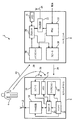
本発明が実施され得るユーザ4のMPERS2の部分は図1に示されている。MPERS2は、モバイルデバイス6とベースユニット8とを有する。
The portion of
モバイルデバイス6は、如何なる適切な形式(例えば、ユーザの首の周りに装着されるペンダント、腕時計、移動電話、PDA等)になってもよく、一般的にはユーザ4の近くに存在する。モバイルデバイス6は、ベースユニット8と通信するための送受信回路10及び関連するアンテナ12を有する。送受信回路10は、例えば、Bluetooth(登録商標)又はDECTを含む如何なる適切な通信プロトコルを使用するように構成されてもよい。更に、送受信回路10は、モバイルデバイス6がベースユニット8の範囲内に存在しない場合(例えば、ユーザ4が家から離れている場合)にモバイルデバイス6が遠隔監視ステーションに直接連絡することができるように、モバイル通信プロトコル(例えば、GSM(登録商標)又はCDMA)を使用するように構成されてもよい。
The mobile device 6 can be in any suitable form (eg, a pendant, wristwatch, mobile phone, PDA, etc. worn around the user's neck) and is generally near the
モバイルデバイス6はまた、プロセッサ14と、スピーカ16と、マイクロフォン18とを有する。プロセッサ14は、モバイルデバイス6の動作を制御する。スピーカ16は、(モバイルデバイス6がベースユニット8の範囲内に存在する場合)ベースユニット8を介して遠隔監視ステーションから受信したオーディオ(通常では音声)を出力するために提供される。図1では、ブロック16はまた、スピーカ16に関連する他の構成要素(例えば、デジタル・アナログ変換器及びオーディオ増幅器)も表す。
The mobile device 6 also has a
マイクロフォン18は、ユーザ4からのオーディオ(この場合も通常では音声)を検出し、(この場合も同様に、モバイルデバイス6が範囲内に存在する場合にベースユニット8を介して)オーディオを遠隔監視ステーションに送信するための電気信号に変換する。
The
モバイルデバイス6はまた、電力をモバイルデバイス6の様々な構成要素に供給するバッテリ20又は他の適切な電源を有する。プロセッサ14は、どの構成要素(例えば、送受信回路10、スピーカ16及びマイクロフォン18)がいずれか特定の時間にバッテリ20により電力供給されるかを制御するように構成されてもよい。
The mobile device 6 also has a
或る実施例では、モバイルデバイス6は、モバイルデバイス6のスピーカ16により再生される予め記録されたオーディオファイルを格納するメモリ21を含んでもよい。これらのオーディオファイルは、スピーカ16が電力供給されている場合に、緊急状態の際に出力されてもよい(例えば、遠隔監視ステーションへの接続が確立されていることをユーザ4に通知するため)。
In some embodiments, the mobile device 6 may include a
ベースユニット8は、モバイルデバイス6と通信するための送受信回路22及び関連するアンテナ24を有する。モバイルデバイス6と同様に、ベースユニット8の送受信回路22は、例えば、Bluetooth(登録商標)又はDECTを含む如何なる適切な通信プロトコルを使用するように構成されてもよい。更に、送受信回路22は、ベースユニット8が遠隔監視ステーションに連絡することを可能にするため、モバイル通信プロトコル(例えば、GSM(登録商標)又はCDMA)を使用するように構成されてもよい。或いは又は更に、送受信回路22は、ユーザの家の壁のソケットを介して公衆電話網(PSTN:public switched telephone network)に接続するように構成されてもよい。
The
ベースユニット8はまた、プロセッサ26と、スピーカ28と、マイクロフォン30とを有する。プロセッサ26は、ベースユニット8の動作を制御する。スピーカ28は、遠隔監視ステーションから受信したオーディオ(通常では音声)を出力するために提供される。或る実施例では、ベースユニット8は、緊急呼び出し中に自動的に再生するためのモバイルデバイス6のメモリ21に格納されたものと同じ予め記録されたオーディオファイルを含むメモリ31を有する。
The
マイクロフォン30は、ユーザ4からのオーディオ(この場合も通常では音声)を検出し、オーディオを遠隔監視ステーションに送信するための電気信号に変換する。
The
ベースユニット8はまた、ユーザの家の電源に接続し、ベースユニット8の様々な構成要素に電力を供給する電源ユニットPSU32を有する。PSU32はまた、電源に中断が存在する場合又は電源が停止した場合にバックアップ電源として機能するバッテリ又は他の適切な電源を含んでもよい。
The
前述のように、本発明は、音響測定のみに基づいて、リアルタイムでベースユニット8からのユーザ4の距離を適応的に判定する方法を提供する。このように、ユーザ4がベースユニット8の近くに存在すると思われる場合、モバイルデバイス6のスピーカ16はオフになってもよく、オーディオは代わりにベースユニット8のスピーカ28によって単に出力されてもよい。しかし、ユーザ4がベースユニット8のスピーカからの音を明瞭に聞いて理解するにはベースユニット8から離れすぎているところに存在する場合、モバイルデバイス6のスピーカ28は、緊急呼び出し中にオンにされてもよい(モバイルデバイス6がベースユニットの無線範囲外に存在する場合も同様)。
As described above, the present invention provides a method for adaptively determining the distance of the
無線(すなわち、RF)に基づく近接法とは異なり、本発明の実施例は、残響(reverberation)のような効果を考慮に入れることができるため、ベースユニット8により取得された音声信号の品質が測定されること、及び/又はモバイルデバイス6で受信したベースユニット8からの音声信号の品質が測定されることを可能にする。例えば、ユーザ(又はベースユニット8)が音源(すなわち、ユーザ4又はベースユニットのスピーカ28)からの残響半径(臨界距離としても知られる)の外部に存在し、音源の直接寄与(direct contribution)及び拡散寄与(diffuse contribution)が強度において等しい場合、モバイルデバイス6のスピーカ16がオンにされるべきである。
Unlike proximity methods based on radio (ie RF), embodiments of the present invention can take into account effects such as reverberation, so that the quality of the audio signal acquired by the
遠隔監視ステーションへの呼び出し中にモバイルデバイスを動作する方法を示すフローチャートが図2に示されている。ステップ101において、モバイルデバイス6は、遠隔監視ステーションへの呼び出しを開始する。呼び出しは、ユーザ4がモバイルデバイス6の緊急又は他のボタンを押下することにより起動されてもよく、モバイルデバイス6の1つ以上のセンサが緊急イベント(ユーザ4による転倒等)を検出することにより起動されてもよい。
A flowchart illustrating a method of operating a mobile device during a call to a remote monitoring station is shown in FIG. In
ステップ103において、モバイルデバイス6は、ベースユニット8の無線範囲内に存在するか否かを判定する。これは、例えばモバイルデバイス6がベースユニット8からの信号を受信できるか否かを判定することにより判定されてもよい。当業者はこれが判定可能な別の方法を認識する。
In
モバイルデバイス6がベースユニット8の無線範囲内に存在しない場合、モバイルデバイス6は、その送受信回路10及びアンテナ12を使用して遠隔監視ステーションに直接連絡する。この場合、モバイルデバイス6の送受信回路10、スピーカ16及びマイクロフォン18は電力供給される(ステップ107)。
If the mobile device 6 is not within the radio range of the
モバイルデバイス6がベースユニット8の無線範囲内に存在する場合、モバイルデバイス6は、ベースユニット8に無線接続し、ベースユニット8は遠隔監視ステーションとの呼び出しを確立する(ステップ109)。この場合、送受信回路10のGSM(登録商標)/CDMA部(これはベースユニット8への無線接続を確立するために使用されるものと別のモジュールでもよい)は、電源オフにされてもよい。
If the mobile device 6 is within the radio range of the
ステップ111において、遠端のユーザが動作中であるか否かが判定される。遠端のユーザは、オーディオ(典型的には音声)をユーザ4に提供する遠隔監視システム(例えば、対応センタ)の人又はコンピュータである。このオーディオは、ベースユニット8のスピーカ28又はモバイルデバイス6のスピーカ16により出力される。瞬時電力を何らかの長期の雑音レベル推定と比較する基本的な電力に基づく方法のように、遠端のユーザの動作(すなわち、音声)を検出する複数の方法が存在する。当業者は、遠端の動作が検出できる別の方法を認識する。
In
遠端のユーザが動作中である場合、ベースユニット8とモバイルデバイス6との間の距離が遠端信号(far-end signal)を使用して判定される。遠端信号は、図1の矢印34及び36によりそれぞれ示されるように、モバイルデバイス6のマイクロフォン18により受信されたスピーカ16及びスピーカ28によるオーディオ出力であることが好ましい。これは図2のステップ113である。
If the far-end user is operating, the distance between the
遠端信号を使用する別法として、ベースユニット8とモバイルデバイス6との間の距離は、スピーカ16及びスピーカ28により出力された格納済みのオーディオファイルからの音を使用して判定されてもよい。
As an alternative to using far-end signals, the distance between the
遠端のユーザが動作中ではない場合(例えば、遠端のユーザがユーザ4の音声を聞いている場合)又はベースユニット8がスピーカで音を発生している場合、ベースユニット8とモバイルデバイス6との間の距離は近端信号(near-end signal)を使用して判定される。近端信号は、図1の矢印38及び40によりそれぞれ示されるように、モバイルデバイス6のマイクロフォン18及びベースユニット8のマイクロフォン30により受信されたユーザ4からのオーディオ(すなわち、音声)である。これは図2のステップ115である。近端のユーザの動作の検出は、遠端のユーザと同様に実行されてもよく、当業者は、近端の動作が検出できる別の方法を認識する。
The
モバイルデバイス6とベースユニット8との間の距離がステップ113又は115で判定された場合、モバイルデバイス6がベースユニット8への音響上の近くに存在するか否か(すなわち、ユーザ4がベースユニット8のスピーカ28により出力された音声を明瞭に聞いて理解できるのに十分なほど、ユーザ4及びモバイルデバイス6がベースユニット8の近くに存在するか?)が判定される。
If the distance between the mobile device 6 and the
モバイルデバイス6がベースユニット8の音響上の近くに存在する場合、モバイルデバイス6のスピーカ16はオフにされてもよい(ステップ119)。モバイルデバイス6がベースユニットの音響上の近くに存在しない場合、モバイルデバイス6のスピーカ16はオンにされてもよい(ステップ121)。
If the mobile device 6 is in the acoustic vicinity of the
ステップ119及び121の後に、この方法はステップ111に戻って繰り返してもよい。
After
或いは、モバイルデバイス6がベースユニット8への音響上の近くに存在するか否かについての判定を行うために双方の測定結果を使用する前に、遠端信号(又はオーディオファイルに基づく信号)及び近端信号の双方の測定が行われてもよい。
Alternatively, before using both measurements to make a determination as to whether the mobile device 6 is acoustically close to the
本発明の実施例の以下の説明は、適応フィルタリングを使用して2つの信号の間の相関を判定することを示す。2つの信号の間の相関又は類似性は、相互相関関数を直接使用することにより判定されてもよいことが分かる。適応フィルタリングの簡単な説明が以下に与えられる。 The following description of embodiments of the present invention illustrates using adaptive filtering to determine the correlation between two signals. It can be seen that the correlation or similarity between two signals may be determined by directly using the cross-correlation function. A brief description of adaptive filtering is given below.
適応フィルタは、他の信号に存在する相関信号を除去するために使用され、一般的には音響的なエコーキャンセルのために使用される。音響的なエコーキャンセルでは、適応フィルタは、デバイスのスピーカとマイクロフォンとの間の音響エコー経路の線形部をモデル化することにより、(線形)音響エコーがマイクロフォン信号から除去され、所望の明瞭な音声信号のみを残すことができるようにする。正確にモデル化された場合、適応フィルタの係数は、図3に示す音響エコー経路に対応し、スピーカとマイクロフォンとの間の直接のカップリング及び何らかの初期の反射に対応する直接音場と、後の反射に対応して残響に寄与する拡散音場とに分割され得る。図3は、高い残響時間(約850ms)を備えた部屋での音響インパルス応答を示しており、直接音場及び拡散音場を示している。y軸は波形の振幅を表し、x軸は8kHzでサンプリングされたインパルス応答の離散時間サンプルを示している。 Adaptive filters are used to remove correlation signals present in other signals, and are typically used for acoustic echo cancellation. For acoustic echo cancellation, the adaptive filter models the linear portion of the acoustic echo path between the device's speaker and microphone, thereby removing (linear) acoustic echo from the microphone signal and producing the desired clear speech. Only leave the signal. When modeled correctly, the adaptive filter coefficients correspond to the acoustic echo path shown in FIG. 3, the direct coupling between the speaker and the microphone and the direct sound field corresponding to some initial reflection, and the Can be divided into a diffuse sound field that contributes to the reverberation in response to the reflections of FIG. 3 shows the acoustic impulse response in a room with a high reverberation time (approximately 850 ms), showing a direct sound field and a diffuse sound field. The y-axis represents the amplitude of the waveform and the x-axis represents a discrete time sample of the impulse response sampled at 8 kHz.
Wienerフィルタ理論に基づく最小平均二乗(LMS:least-mean-square)、正規化LMS(NLMS:normalized LMS)及び再帰的最小二乗(RLS:recursive least squares)並びにKalmanフィルタリングのような複数の適応フィルタリングアルゴリズムが存在する。以下の実施例では、最適な適応フィルタの係数を導くために、Wienerフィルタ理論が使用される。 Multiple adaptive filtering algorithms such as least-mean-square (LMS), normalized LMS (NLMS) and recursive least squares (RLS) and Kalman filtering based on Wiener filter theory Exists. In the following example, Wiener filter theory is used to derive the optimal adaptive filter coefficients.
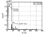
図4の上部のグラフ(図4A)は、受信デバイス(例えば、ベースユニット8)の近く(例えば、1.6m)に立つユーザの二乗振幅(squared-magnitude)の適応フィルタのインパルス応答を示しており、図4の下部のグラフ(図4B)は、受信デバイス(例えば、ベースユニット8)から離れて(例えば、3m)立つユーザの二乗振幅の適応フィルタのインパルス応答を示している。インパルス応答の最初の大きいピークは、モバイルデバイス6のスピーカ16とマイクロフォン18との間の音響経路に対応し、遅延したピークの第2のセットは、ベースユニット8のスピーカ28とモバイルデバイス6のマイクロフォン18との間の音響経路に対応する。
The top graph of FIG. 4 (FIG. 4A) shows the impulse response of a user's squared-magnitude adaptive filter that stands near (eg, 1.6 m) a receiving device (eg, base unit 8). The lower graph of FIG. 4 (FIG. 4B) shows the impulse response of the user's square amplitude adaptive filter standing away (eg, 3 m) from the receiving device (eg, base unit 8). The first large peak of the impulse response corresponds to the acoustic path between the
低い残響時間を有するいわゆるドライルーム(dry room)では、インパルス応答の拡散部は、直接音場に比べて電力がかなり低い。更に、音源(例えばユーザの口)が受信デバイス(例えば、ベースユニット)に近くに存在するほど、直接音場と拡散音場との強度の比が大きくなる。受信デバイスの周囲の残響半径又は臨界距離において、直接音場の強度は拡散音場の強度と等しくなる。この半径の外側では、拡散寄与のみが存在し、ベースユニットのマイクロフォンにより取得された音声の明瞭性がかなり低下する。これは、距離(すなわちRF)に基づく距離検出の対策が考慮できない問題である。 In a so-called dry room with low reverberation time, the diffuse part of the impulse response has a much lower power than the direct sound field. Furthermore, the closer the sound source (eg, the user's mouth) is to the receiving device (eg, the base unit), the greater the ratio of the intensity of the direct sound field to the diffuse sound field. At the reverberation radius or critical distance around the receiving device, the intensity of the direct sound field is equal to the intensity of the diffuse sound field. Outside this radius, there is only a diffusion contribution and the clarity of the speech acquired by the base unit microphone is considerably reduced. This is a problem in which a measure for distance detection based on distance (that is, RF) cannot be considered.
本発明の第1の実施例における処理を示す図は、図5に示されている。モバイルデバイス6とベースユニット8との間の近さを判定する対応する方法を示すフローチャートは、図6に示されている。
A diagram showing the processing in the first embodiment of the present invention is shown in FIG. A flowchart illustrating a corresponding method of determining proximity between the mobile device 6 and the
本発明の第1の実施例では、適応フィルタは、好ましくは2つの信号の2つのセットを使用して、(モバイルデバイス6を有する)ユーザとベースユニット8との間の距離を判定するために、ピーク検出方式と組み合わされる。第1の実施例は、図2のステップ113に示すように、ベースユニット8のスピーカ28から出力されたオーディオ(すなわち、遠端音響信号又はベースユニット8のメモリ31に格納されたオーディオファイルから生成された音響信号)の使用に基づく。
In the first embodiment of the invention, the adaptive filter preferably uses two sets of two signals to determine the distance between the user (with mobile device 6) and the
特に、近さの検出は、モバイルデバイス6のマイクロフォン18により検出されたときのモバイルデバイス6のスピーカ16により生成されたエコー信号(この信号の直接音場はスピーカ16とマイクロフォン18との間の強いカップリングと短い遅延とに関連する)と、モバイルデバイス8のマイクロフォン18により検出されたときのベースユニット8のスピーカ28により生成されたエコー信号(このエコーは、モバイルデバイス6(すなわち、ユーザ)とベースユニット8との間の距離に依存するカップリングに関連する)とに基づく。第1のエコー信号の直接音場に対する第2のエコー信号の遅延は、モバイルデバイス6とベースユニット8との間の距離に比例する。
In particular, proximity detection is the echo signal generated by the
この第1の実施例では、本発明に従って実行される処理は、モバイルデバイス6のプロセッサ14により実行されることが好ましいが、この処理は代わりにベースユニット8のプロセッサ26により実行されてもよいことが分かる。
In this first embodiment, the processing performed in accordance with the present invention is preferably performed by the
図5は、(周波数ωの)周波数領域での第1の実施例を示している。プロセッサ14による処理は、モバイルデバイス6のスピーカ16とそのマイクロフォン18との間の適応フィルタ42と、ユーザ4(モバイルデバイス6)とベースステーション8との間の距離を計算する論理ユニット44とで構成される。
FIG. 5 shows a first embodiment in the frequency domain (of frequency ω). The processing by the
結果の適応フィルタの解におけるモバイルデバイス6とベースユニット8との間との間の無線符号化/復号化処理の効果を理解するために、ベースステーション8からモバイルデバイス6に音声信号を送信するために使用される音声符号化器46及び復号化器48の数学モデルが含まれる(この音声符号化器46はベースユニット8のプロセッサ26により実装され、復号化器48はモバイルデバイス6のプロセッサ14により実装される)。符号化動作は、時間変化するフィルタリング及び量子化動作としてモデル化されてもよい。音響エコーキャンセラによって補償可能であるベースユニット8とモバイルデバイス6との間の無線チャネルにおけるチャネル遅延とは別に、無線チャネルのパケットロス及び他の非線形歪みがこの分析の目的で無視される。
To transmit the audio signal from the
図5において、遠隔監視ステーションからベースユニット8で受信された遠端信号データ(又は格納されたオーディオファイル)は、音響信号としてベースステーション8のスピーカ28により出力されるX(ω)により示される(図6のステップ201)。遠端信号データはまた、モバイルデバイス6に無線送信され、その後、符号化及び無線チャネル(C(ω))を通じた送信が復号化され、音響信号としてモバイルデバイス6のスピーカ16により出力される(図6のステップ203)。
In FIG. 5, the far-end signal data (or stored audio file) received by the
![]()
![]()
Q(ω)=0及びC(ω)=e-jωδ(δは送信遅延である)である理想的な状況を仮定すると、モバイルデバイス6のマイクロフォン18により生成された音響信号(ステップ205)は以下により与えられる。
Assuming an ideal situation where Q (ω) = 0 and C (ω) = e −jωδ (δ is the transmission delay), the acoustic signal generated by the
![]()
![]()
![]()
![]()
しかし、通常の状況では、符号化器46は、電力
However, in normal circumstances, the
![]()
![]()
遠端信号データ(又はオーディオファイルデータ)は、適応フィルタ42の出力と受信信号Y(ω)との間の平均二乗誤差を最小化するための適応フィルタ42の係数を判定するために使用される(ステップ207)。
The far end signal data (or audio file data) is used to determine the coefficients of the
適応フィルタの重みの最適な解は、(ユーザ4が話し中でなく、受信信号Y(ω)にオーディオを寄与していないという仮定で)以下のように導かれてもよい。
The optimal solution for the adaptive filter weights may be derived as follows (assuming that
式(1)及びC(ω)=1であるという仮定に従い、モバイルデバイス6のスピーカ16により出力される信号は以下により与えられる。
In accordance with the assumption that Equation (1) and C (ω) = 1, the signal output by the
![]()
![]()
![]()
![]()
モバイルデバイス6のマイクロフォン18により受信された信号は以下により与えられる。
The signal received by the
![]()
![]()
![]()
![]()
![]()
![]()
フィルタの出力42とマイクロフォン18で受信される音響信号との間の平均二乗誤差(MSE:mean square error)を最小化する最適な重みW(ω)はWienerの解によって以下により与えられる。
The optimal weight W (ω) that minimizes the mean square error (MSE) between the

以下の理由で、第2及び第3の項の予想はゼロになる。 For the following reasons, the predictions of the second and third terms are zero.
![]()
![]()
NLMSのような最小平均二乗アルゴリズムは、適応フィルタの係数を更新し、最適なWienerの解における変化を把握するために使用されてもよい。この適応は、残差信号(residual signal)51で適応フィルタの入力信号を相関させることにより実行される。NLMS係数の更新の再帰は以下により与えられる。
A least mean square algorithm such as NLMS may be used to update the adaptive filter coefficients and keep track of changes in the optimal Wiener solution. This adaptation is performed by correlating the input signal of the adaptive filter with a
![]()
![]()
チャネル遅延及び信号処理(すなわち、符号化及び復号化)により生じる遅延に関して、大きすぎる遅延は、HmとHbとの間の時間差の正確な推定に影響を与える可能性がある。この理由は、これは処理のグループ遅延にチャネル遅延を加えたものに等しい量だけ遅延したHmを有するWienerの解を生じるからである。従って、図5の上の分岐のブロック52により示すように、補償遅延がスピーカ28の出力に適用されてもよい。
With respect to the delay caused by channel delay and signal processing (ie, encoding and decoding), a delay that is too large can affect the accurate estimation of the time difference between H m and H b . This is because this results in a Wiener solution with H m delayed by an amount equal to the group delay of the process plus the channel delay. Accordingly, a compensation delay may be applied to the output of the
Wienerの解がモバイルデバイス6のスピーカ16とマイクロフォン18との間の個々の音響エコー経路に関して表現されているため、論理ユニット44(プロセッサ14)は、モバイルデバイス6がベースユニット8に近いか否かを判定する(従って、好ましい実施例では、モバイルデバイス6のスピーカ18をオフにするか否かを判定する)。
Since the Wiener solution is expressed in terms of individual acoustic echo paths between the
特に、論理ユニット44は、音響インパルス応答のエネルギー(例えば、図3に示す)を検査し、モバイルデバイス6のスピーカ16に関連する直接音場とベースユニット8のスピーカ28に関連するエコー経路の直接音場とを見つける(図6のステップ211)。
In particular, the
ステップ211の前に、適応フィルタの係数の振幅二乗(magnitude square)が平滑化されることが好ましい。以下では、適応フィルタの係数の振幅二乗を平滑化するために、移動平均(MA:moving average)フィルタが使用される。この有限インパルス応答フィルタ(FIR:finite impulse response filter)は以下により与えられる。 Prior to step 211, the magnitude square of the adaptive filter coefficients is preferably smoothed. In the following, a moving average (MA) filter is used to smooth the amplitude square of the coefficients of the adaptive filter. This finite impulse response filter (FIR) is given by:
論理ユニット44は、図6のステップ211において、平滑化された振幅のインパルス応答の局所最大値、すなわち、左右の隣接するサンプルの双方より大きい振幅を有するサンプル、すなわち、
The
![]()
![]()
2番目に大きい局所最大値は、ベースユニット8からのエコー経路(Hb)のインパルス応答に対応するものとして得られてもよい。これとグローバル最大値(すなわち、モバイルデバイス6のスピーカ16からのエコー経路Hm)との間の距離dは、モバイルデバイス6/ユーザ4とベースユニット8との間のサンプル距離に対応する(図6のステップ213)。この距離は、以下に従ってメートルの距離に変換される。
The second largest local maximum may be obtained as corresponding to the impulse response of the echo path (H b ) from the
この値に応じて、以下のようになる。
D≧Th1の場合、Sw=1(すなわち、スピーカ16がオンになる) (21)
D<Th1の場合、Sw=0(すなわち、スピーカ16がオフになる) (22)
ただし、Th1は何らかの閾値距離(例えば、Th1=3m)である。モバイルデバイス6のスピーカ16に関連する直接音場とベースユニット8のスピーカ28に関連するエコー経路の直接音場との間の距離を判定するために全体のインパルス応答におけるピークを識別する他の方法が存在することが分かる。
Depending on this value:
If D ≧ Th1, Sw = 1 (ie, the
If D <Th1, Sw = 0 (ie,
However, Th1 is some threshold distance (for example, Th1 = 3m). Other methods of identifying peaks in the overall impulse response to determine the distance between the direct sound field associated with the
更に、グローバル最大値の振幅に比較して、ベースユニット8のスピーカ28からのエコー経路のインパルス応答に対応する2番目に大きい最大値の振幅は、他の指標として(又は距離の指標と共に)使用されてもよい。すなわち、
p2/pmax≧2の場合、Sw=0(すなわち、スピーカ16がオフになる) (23)
その他の場合、Sw=1(すなわち、スピーカ16がオンになる) (24)
ただし、Th2は、ベースユニット8のスピーカの増幅器の利得に応じた何らかの閾値であり、好ましくは1未満であり、pmaxはグローバル最大値の振幅であり、p2は2番目に大きい最大値の振幅である。閾値Th2はスピーカ16及び23の増幅器の設定に基づいて実験的に判定されてもよい。距離の指標とは異なり、この指標は、ユーザ4とモバイルデバイス6とベースユニット8との間の音響経路の品質を考慮に入れる(すなわち、反射及び残響のため音響エネルギーのロスが存在する場合)。
In addition, the second largest maximum amplitude corresponding to the impulse response of the echo path from the
When p 2 / p max ≧ 2, Sw = 0 (ie, the
Otherwise, Sw = 1 (ie,
However, Th2 is some threshold according to the gain of the amplifier of the speaker of the
残響量の指標としての2番目のピークの周辺のインパルス応答の分散の使用のように、ユーザ4とモバイルデバイス6とベースユニット8との間の音響品質を評価する他の指標も存在することが分かる。この分散は、以下のような局所化された散在性の指標に基づいてもよい。
There may be other indicators that evaluate the acoustic quality between the
第1の実施例の前述の説明は、モバイルデバイス6のスピーカ16がオンであることを想定しており、ベースユニット8からのエコーに対応するインパルス応答が適応フィルタ42の平滑化された振幅二乗の応答の2番目に大きい最大値により与えられることが分かる。
The above description of the first embodiment assumes that the
しかし、処理が行われている間に(初期設定により又はスピーカ16をオフにするという以前の判定に従って)モバイルデバイス6のスピーカ16がオフである場合、ベースユニット8に対応するインパルス応答は、適応フィルタの平滑化された振幅二乗の応答のグローバル最大値により与えられる。これは、問題に対する更にロバストな解になり得る。この場合、モバイルデバイス6は、依然としてモバイルデバイス6とベースユニット10との間の無線接続で遠端信号データを受信し(又は既にメモリ21に格納されたオーディオファイルを有しており)、この信号又はファイルを前述の処理ステップで使用する。グローバル最大値の位置は、代わりに第1のフィルタタップを基準点として使用することにより、スピーカ16からのエコー経路から導かれた基準点のない距離に変換される。モバイルデバイス6のスピーカ16はマイクロフォン18に非常に近いため、最初の局所ピークはいずれの場合でも通常では最初の数個の適応フィルタ係数の中に存在するため、このことは許容可能である。更に、スピーカ16がオフである場合、Th2を用いた電力の指標が使用不可能であるが、距離及び分散の指標は依然として使用可能である。
However, if the
いずれの場合でも(すなわち、スピーカ16及び関連する構成要素がオンであれ、オフであれ)、モバイルデバイス6のマイクロフォン18がオンである限り、処理は呼び出し中にバックグラウンドで適応的に実行してもよい。
In any case (ie, whether the
スピーカ28からの出力が格納されたオーディオファイルから生成される場合、前述の処理は、符号化器46及び復号化器48が必要ないという点で異なる。従って、Q(ω)=0及びA(ω)=1である。第1の実施例のこの実装では、呼び出しが開始された場合、ベースユニット8に対して呼び出しを開始させて予め記録されたオーディオファイルをメモリ31から再生させるトリガー信号が、モバイルデバイス6からベースユニット8に送信されてもよい。同時に、オーディオファイルは、モバイルデバイス6のメモリ21から抽出され、適応フィルタに供給される(この実装では、前述の実施例と同様に、モバイルデバイス6のスピーカ16を通じたオーディオファイルの出力は同様に必ずしも必要であるとは限らない)。このようにオーディオファイルを出力することは、呼び出しを確立するためにモバイルデバイス6とベースユニット8との間に必要なシグナリングの量と、近さ又は音響品質を判定するために必要な処理とに関して、本発明の第1の実施例の最も効率的な実装を提供する。
When the output from the
また、遠端信号がモバイルデバイス6及びベースユニット8に直接提供されることも可能であることが分かる。この場合、処理は、前の段落に記載した格納されたオーディオファイルの実施例と同様になる。
It can also be seen that the far-end signal can be provided directly to the mobile device 6 and the
モバイルデバイス6のスピーカから受信した音響信号(スピーカ16が動作中である場合)と共に、モバイルデバイス6のマイクロフォン18においてベースユニット8のスピーカ28から受信した音響信号(音響信号は遠端の発信源又は格納されたオーディオファイルからのものである)の分析を参照して第1の実施例について説明したが、モバイルデバイス6とベースユニット8との間の距離又は音響品質は、代わりに、ベースユニット8からモバイルデバイス6のマイクロフォン18で受信した音響信号と、ベースユニット8のスピーカ28により出力されてマイクロフォン30により受信された対応するオーディオ信号とを分析することにより、判定されてもよいことが分かる。当業者により認識できるように、これらの実装に必要な処理は、前の段落に記載したものと概して同様になる。
Along with the acoustic signal received from the speaker of the mobile device 6 (when the
第1の実施例への更なる変形では、モバイルデバイス6とベースユニット8との間の距離は、モバイルデバイス6のスピーカ16により出力されているベースユニット8のマイクロフォン30で受信した音響信号を、任意選択で、モバイルデバイス6のスピーカ16からモバイルデバイス6のマイクロフォンで受信した同じ音響信号、又はベースユニット8のスピーカ28により出力されているベースユニット8のマイクロフォン30で受信した同じ音響信号と共に分析することにより判定されてもよい。この場合も当業者に認識できるように、これらの実装に必要な処理は、前の段落に記載したものと概して同様になる。しかし、これらの実装は、モバイルデバイス6のスピーカにより出力されたオーディオが一般的にベースユニット8により出力されたオーディオほど大きくないため(部分的には電力及びサイズの制約のため、及びモバイルデバイス6が使用中にユーザ4の近くにある可能性が高いため)、あまり好ましくない。従って、ベースユニット8で受信した信号のピークは、それほど強くない可能性が高い。
In a further modification to the first embodiment, the distance between the mobile device 6 and the
本発明の第2の実施例における処理を示す図は、図8に示されている。モバイルデバイス6とベースユニット8との間の近さを判定する対応する方法を示すフローチャートは、図9に示されている。
A diagram showing the processing in the second embodiment of the present invention is shown in FIG. A flowchart illustrating a corresponding method of determining proximity between the mobile device 6 and the
本発明の第2の実施例では、適応フィルタは、同様に、好ましくは2つの信号の2つのセットを使用して、(モバイルデバイス6を有する)ユーザ4とベースユニット8との間の距離を判定するために、ピーク検出方式と組み合わされる。第2の実施例は、図2のステップ115に示すように、近端信号の使用に基づく。
In the second embodiment of the present invention, the adaptive filter similarly uses the two sets of two signals, preferably to determine the distance between the user 4 (with the mobile device 6) and the
特に、近さの検出は、モバイルデバイス6のマイクロフォン18により検出されたときのモバイルデバイス6のユーザ4の音声により生成された信号(この信号の直接音場はユーザ4とマイクロフォン18との間の強いカップリングと短い遅延とに関連する)と、ベースユニット8のマイクロフォン18でユーザ4の音声により生成された同じ信号(この信号は、ユーザ4(すなわち、モバイルデバイス6)とベースユニット8との間の音響環境及び距離に依存するカップリングに関連する)とに基づく。第1の信号の直接音場に対する第2の信号の遅延は、モバイルデバイス6とベースユニット8との間の距離に比例する。
In particular, the proximity detection is a signal generated by the voice of the
この第2の実施例では、本発明に従って実行される処理は、ベースユニット8のプロセッサ26により実行されることが好ましいが、この処理は代わりにモバイルデバイス6のプロセッサ14により実行されてもよいことが分かる。
In this second embodiment, the processing performed according to the present invention is preferably performed by the
本発明のこの実施例は、モバイルデバイス6のスピーカ16を利用しないため、スピーカ16がオンであるか否かは関係ない。
This embodiment of the present invention does not use the
モバイルデバイス6のマイクロフォン18は、ユーザ4からのオーディオ(すなわち、音声)S(ω)を検出し(図9のステップ301)、受信したオーディオ信号X(ω)をチャネルC(ω)を解してベースユニット8に送信する(ステップ303)。
The
ベースユニット8のマイクロフォン30もまた、ユーザ4からの同じオーディオ(すなわち、音声)S(ω)を検出する(ステップ305)。
The
プロセッサ26による処理は、適応フィルタ54と、モバイルデバイス6のマイクロフォン18及びベースユニット8のマイクロフォン30に到達する信号の間の遅延を計算する論理ユニット56とで構成される。
The processing by the
同様に、モバイルデバイス6からベースステーション8に音声信号X(ω)を送信するために使用される音声符号化器58のモデル60が、分析を支援するために含まれる(この音声符号化器58はモバイルデバイス6のプロセッサ14により実装され、復号化器60はベースユニット8のプロセッサ26により実装される)。第1の実施例と同様に、符号化動作は、時間変化するフィルタリング及び量子化動作としてモデル化されてもよい。音響エコーキャンセラによって補償可能であるベースユニット8とモバイルデバイス6との間の無線チャネルにおけるチャネル遅延とは別に、無線チャネルのパケットロス及び他の非線形歪みがこの分析の目的で無視される。
Similarly, a
処理は、第1実施例と同様に実行される。すなわち、適応フィルタの係数は、信号の平均二乗誤差を最小化するように判定され(ステップ307)、係数の振幅二乗が任意選択で平滑化され(ステップ309)、受信信号のそれぞれにおけるユーザの音声に関連する直接音場が識別され(ステップ311)、モバイルデバイス6とベースユニット8との間の距離が識別された直接音場から判定される(ステップ313)。
The process is executed in the same manner as in the first embodiment. That is, the coefficients of the adaptive filter are determined so as to minimize the mean square error of the signal (step 307), the amplitude square of the coefficient is optionally smoothed (step 309), and the user's voice in each of the received signals Is identified (step 311), and the distance between the mobile device 6 and the
特に、MMSEの意味での適応フィルタの重みの最適な解は、Wienerの解により与えられる。 In particular, the optimal solution for the weight of the adaptive filter in the MMSE sense is given by the Wiener solution.
![]()
![]()
(26)の分子及び分母は、それぞれ以下のように更に簡略化されてもよい。 The numerator and denominator of (26) may be further simplified as follows.
![]()
![]()
![]()
![]()
![]()
![]()
ユーザ4とベースユニット8との間の距離は、閾値距離Th3(これはTh1と同じでもよい)と比較されてもよい。この値に応じて、以下のようになる。
D≧Th3の場合、Sw=1(すなわち、スピーカ16がオンになる) (35)
D<Th3の場合、Sw=0(すなわち、スピーカ16がオフになる) (36)
第1の実施例と同様に、音声の音響品質は、音響インパルス応答から判定されてもよい。これは、前述の式23、24及び25に基づいてもよい。
The distance between the
When D ≧ Th3, Sw = 1 (ie, the
If D <Th3, Sw = 0 (ie,
Similar to the first embodiment, the acoustic quality of speech may be determined from the acoustic impulse response. This may be based on
この第2の実施例はまた、サンプル遅延τ<Nの間に、以下のように図8の時間領域の信号Yb及びYの間の相互相関を直接計算することにより実施されてもよいことが分かる。 This second embodiment may also be implemented during the sample delay τ <N by directly calculating the cross-correlation between the time domain signals Yb and Y of FIG. 8 as follows: I understand.
前述のように、図2の方法は、各信号が動作中になったときに遠端及び近端の信号の双方の分析を使用して動作してもよく、近さの判定は、双方の測定の結果に基づいて行われてもよい。例えば、一方の実施例がSw=1(すなわち、スピーカ16をオンにする)を出力し、他方の実施例がSw=0(すなわち、スピーカ16をオフにする)を出力した場合、この不確実性を鑑みて最終判断は、モバイルデバイス6のスピーカ16をオンに保持することでもよい。
As described above, the method of FIG. 2 may operate using both far-end and near-end signal analysis as each signal becomes active, It may be performed based on the result of the measurement. For example, if one embodiment outputs Sw = 1 (ie,
例えば、モバイルデバイス6とベースユニット8との間では8kHzでサンプリングされたオーディオの送信を妨げるという、モバイルデバイス6とベースユニット8との間の無線チャネルに帯域幅の制限が存在する前述の第1及び第2の実施例の変形では、音響信号は、モバイルデバイス6とベースユニット8との双方で粗い表現に変換されてもよい。この表現は、モバイルデバイス6とベースユニット8との間の距離を判定するタイミングの手がかりを保持するが、モバイルデバイス6とベースユニット8との間の音響経路又は距離により生じる音響品質の劣化を判定するための信号の特性に関する他の特徴を伝達する。
For example, there is a bandwidth limitation on the radio channel between the mobile device 6 and the
信号のタイミングの重要な手がかりを保持し、依然として適応フィルタリングの動作を利用する表現は、修正(rectification)の形式での信号の平滑化と、信号の包絡線(envelope)の計算とを含む。この動作はまた、1秒当たりの送信サンプルの数を低減するために、フィルタをアンチエイリアシング(anti-aliasing)して信号をダウンサンプルすることにより後続されてもよい。これらの実施例では、送信された音声信号は、遠端の対応センタへの送信に使用できない可能性がある。当業者は、モバイルデバイス6とベースユニット8との間の距離及び音響品質を判定するために使用され得る重要な時間領域の特性を保持する別の信号の表現を認識する。
An expression that retains important clues to the timing of the signal and still uses the operation of adaptive filtering involves smoothing the signal in the form of rectification and calculating the envelope of the signal. This operation may also be followed by anti-aliasing the filter and down-sampling the signal to reduce the number of transmitted samples per second. In these embodiments, the transmitted audio signal may not be available for transmission to the far-end counterpart center. Those skilled in the art will recognize alternative signal representations that retain important time-domain characteristics that can be used to determine the distance and sound quality between the mobile device 6 and the
モバイルデバイス6とベースユニット8との間の音響品質を判定するために使用され得る信号表現は、信号のエネルギー又は高次の統計的モーメント(statistical moment)に関係する。これらは、モバイルデバイス6又はベースユニット8においてあまり頻繁に送信されなくてもよく、比較されなくてもよい。
The signal representation that can be used to determine the acoustic quality between the mobile device 6 and the
本発明の実施例に従って実行される処理は、ハードウェア若しくはソフトウェア又は双方の組み合わせを使用して実装されてもよいことが分かる。 It will be appreciated that the processing performed in accordance with embodiments of the present invention may be implemented using hardware or software or a combination of both.
従って、好ましい実施例では、ベースユニット8のスピーカ28からの音声を聞いて認識するユーザ4の能力を評価した後に、通信中にモバイルデバイス6のスピーカ16の動作に関する判定が行われることを可能にするモバイルデバイス6(及びユーザ4)のベースユニット8への近さを判定するためのRFに基づく方法への代わりの手法について説明した。
Therefore, in the preferred embodiment, after evaluating the ability of the
図面及び前述の説明では、本発明について詳細に例示及び記載したが、このような例示及び記載は、例示的又は例として考えられるべきであり、限定的であると考えられるべきではない。本発明は、開示された実施例に限定されない。 While the invention has been illustrated and described in detail in the drawings and foregoing description, such illustration and description are to be considered illustrative or exemplary and not restrictive; The invention is not limited to the disclosed embodiments.
開示された実施例への変形は、図面、開示及び特許請求の範囲の研究から、特許請求の範囲の発明を実施する際に当業者により理解されて行われてもよい。請求項において、“有する”という用語は他の要素又はステップを除外せず、単数は複数を除外しない。単一のプロセッサ又は他のユニットは、請求項に記載の複数の項目の機能を実行してもよい。特定の手段が相互に異なる従属項に記載されているという単なる事実は、これらの手段の組み合わせが有利に使用できないことを示すものではない。コンピュータプログラムは、他のハードウェアの一部として又はそれと共に、光記憶媒体又はソリッドステート記憶媒体のような適切な媒体に格納/分配されてもよく、インターネット又は他の有線若しくは無線通信システム等を介して他の形式で分散されてもよい。請求項の如何なる参照符号もその範囲を限定するものとして解釈されるべきではない。 Variations to the disclosed embodiments may be made by those of ordinary skill in the art in practicing the claimed invention, from a study of the drawings, the disclosure, and the claims. In the claims, the term “comprising” does not exclude other elements or steps, and the singular does not exclude a plurality. A single processor or other unit may fulfill the functions of several items recited in the claims. The mere fact that certain measures are recited in mutually different dependent claims does not indicate that a combination of these measured cannot be used to advantage. The computer program may be stored / distributed on a suitable medium such as an optical storage medium or a solid-state storage medium as part of or together with other hardware, such as the Internet or other wired or wireless communication system etc. May be distributed in other forms. Any reference signs in the claims should not be construed as limiting the scope.
Claims (15)
前記モバイルデバイス及びベースユニットのうち一方のマイクロフォンにより音響信号を受信するステップと、
前記受信した音響信号と第2の信号との相関を判定するステップと、
前記相関を判定するステップの結果における1つ以上のピークに基づいて前記モバイルデバイスと前記ベースユニットとの間の前記音響品質及び/又は前記距離を判定するステップと
を有する方法。 A method for determining a distance and / or sound quality between a mobile device and a base unit, comprising:
Receiving an acoustic signal by a microphone of one of the mobile device and the base unit;
Determining a correlation between the received acoustic signal and a second signal;
Determining the acoustic quality and / or the distance between the mobile device and the base unit based on one or more peaks in the result of determining the correlation.
前記モバイルデバイス及びベースユニットの一方のマイクロフォンにより音響信号を受信するステップは、前記モバイルデバイス及び前記ベースユニットの前記スピーカから前記音響信号を受信することを有する、請求項2に記載の方法。 Controlling the one speaker of the mobile device and the base unit to output the acoustic signal;
The method of claim 2, wherein receiving an acoustic signal by a microphone of one of the mobile device and base unit comprises receiving the acoustic signal from the speaker of the mobile device and the base unit.
前記モバイルデバイス及びベースユニットのうち前記一方のスピーカからの音響信号に対応する、前記判定するステップの結果における第1のピークと、前記モバイルデバイス及びベースユニットのうち前記他方のスピーカからの前記音響信号に対応する第2のピークとを検出し、前記判定するステップの結果における前記第1のピークと前記第2のピークとの間の距離から、前記モバイルデバイスと前記ベースユニットとの間の距離を判定すること、及び/又は
(i)前記検出されたピークの振幅の比、(ii)前記第2のピークの周辺の分散及び/又は(iii)前記第2のピークの周辺の残響時間から、前記モバイルデバイスと前記ベースユニットとの間の前記音響品質を判定することを有する、請求項6に記載の方法。 Determining the acoustic quality and / or the distance between the mobile device and the base unit comprises:
A first peak in a result of the determining step corresponding to an acoustic signal from the one speaker of the mobile device and the base unit; and the acoustic signal from the other speaker of the mobile device and the base unit. And determining the distance between the mobile device and the base unit from the distance between the first peak and the second peak in the result of the determining step. Determining and / or
From the (i) ratio of amplitudes of the detected peaks, (ii) dispersion around the second peak and / or (iii) reverberation time around the second peak, the mobile device and the base unit The method according to claim 6, further comprising: determining the acoustic quality between.
前記方法は、前記モバイルデバイスのマイクロフォンにより音響信号を受信するステップを更に有し、
前記モバイルデバイスの前記マイクロフォンにより受信された前記音響信号は、受信した音響信号と第2の信号との相関を判定するステップにおける前記第2の信号として使用される、請求項1に記載の方法。 Receiving the acoustic signal comprises receiving the acoustic signal by a microphone of the base unit;
The method further comprises receiving an acoustic signal by a microphone of the mobile device;
The method of claim 1, wherein the acoustic signal received by the microphone of the mobile device is used as the second signal in determining a correlation between the received acoustic signal and a second signal.
請求項1ないし13のうちいずれか1項に記載の方法に従って、前記モバイルデバイスと前記ベースユニットとの間の前記距離及び/又は前記音響品質を判定するステップと、
前記モバイルデバイスが前記ベースユニットへの閾値距離よりも近いこと又は前記音響品質が閾値よりも大きいことが判定された場合、前記モバイルデバイスのスピーカを停止させるステップと
を有する方法。 A method for reducing power consumption of a mobile device, comprising:
Determining the distance and / or the acoustic quality between the mobile device and the base unit according to the method of any one of claims 1 to 13;
Stopping the mobile device speaker if it is determined that the mobile device is closer than a threshold distance to the base unit or that the acoustic quality is greater than a threshold.
ベースユニットと、
プロセッサと
を有するシステムであって、
前記モバイルデバイス及びベースユニットのうち一方は、音響信号を受信するマイクロフォンを有し、
前記プロセッサは、
前記受信した音響信号と第2の信号との相関を判定し、
前記判定するステップの結果における1つ以上のピークに基づいて前記モバイルデバイスと前記ベースユニットとの間の音響品質及び/又は距離を判定するように構成されるシステム。 A mobile device,
A base unit,
A system having a processor,
One of the mobile device and the base unit has a microphone that receives an acoustic signal;
The processor is
Determining a correlation between the received acoustic signal and the second signal;
A system configured to determine an acoustic quality and / or distance between the mobile device and the base unit based on one or more peaks in the result of the determining step.
Applications Claiming Priority (3)
| Application Number | Priority Date | Filing Date | Title |
|---|---|---|---|
| EP11160378.3 | 2011-03-30 | ||
| EP11160378 | 2011-03-30 | ||
| PCT/IB2012/051442 WO2012131570A1 (en) | 2011-03-30 | 2012-03-27 | Determining the distance and/or acoustic quality between a mobile device and a base unit |
Publications (2)
| Publication Number | Publication Date |
|---|---|
| JP2014512127A true JP2014512127A (en) | 2014-05-19 |
| JP6426000B2 JP6426000B2 (en) | 2018-11-21 |
Family
ID=45937497
Family Applications (1)
| Application Number | Title | Priority Date | Filing Date |
|---|---|---|---|
| JP2014501760A Active JP6426000B2 (en) | 2011-03-30 | 2012-03-27 | Determination of distance and / or sound quality between mobile device and base unit |
Country Status (8)
| Country | Link |
|---|---|
| US (1) | US9338278B2 (en) |
| EP (1) | EP2692123B1 (en) |
| JP (1) | JP6426000B2 (en) |
| CN (1) | CN103583033B (en) |
| BR (1) | BR112013024734A2 (en) |
| ES (1) | ES2644529T3 (en) |
| RU (1) | RU2588596C2 (en) |
| WO (1) | WO2012131570A1 (en) |
Cited By (2)
| Publication number | Priority date | Publication date | Assignee | Title |
|---|---|---|---|---|
| JP2014045416A (en) * | 2012-08-28 | 2014-03-13 | Kyocera Corp | Portable terminal, voice control program, and voice control method |
| JP2020531832A (en) * | 2017-08-25 | 2020-11-05 | イーエヌデータクト ゲーエムベーハーiNDTact GmbH | Mobile device with sensor |
Families Citing this family (13)
| Publication number | Priority date | Publication date | Assignee | Title |
|---|---|---|---|---|
| JP2014165887A (en) * | 2013-02-27 | 2014-09-08 | Saxa Inc | Conference terminal and program |
| US9451377B2 (en) | 2014-01-07 | 2016-09-20 | Howard Massey | Device, method and software for measuring distance to a sound generator by using an audible impulse signal |
| EP2899942A1 (en) * | 2014-01-27 | 2015-07-29 | Thomson Licensing | Provision of a network parameter to a client device |
| US20150230043A1 (en) * | 2014-02-12 | 2015-08-13 | Qualcomm Incorporated | Method and apparatus for establishing a personal area network connection |
| US9336767B1 (en) * | 2014-03-28 | 2016-05-10 | Amazon Technologies, Inc. | Detecting device proximities |
| US20170034709A1 (en) * | 2014-04-09 | 2017-02-02 | Ntt Docomo, Inc. | Measurement control method and base station |
| US20160098040A1 (en) * | 2014-10-02 | 2016-04-07 | Harman International Industries, Inc. | Mount for media content presentation device |
| US9997151B1 (en) * | 2016-01-20 | 2018-06-12 | Amazon Technologies, Inc. | Multichannel acoustic echo cancellation for wireless applications |
| CN106131754B (en) * | 2016-06-30 | 2018-06-29 | 广东美的制冷设备有限公司 | Group technology and device between more equipment |
| CN107135445A (en) * | 2017-03-28 | 2017-09-05 | 联想(北京)有限公司 | A kind of information processing method and electronic equipment |
| US10586534B1 (en) * | 2017-09-27 | 2020-03-10 | Amazon Technologies, Inc. | Voice-controlled device control using acoustic echo cancellation statistics |
| US11394425B2 (en) * | 2018-04-19 | 2022-07-19 | Cisco Technology, Inc. | Amplifier supporting full duplex (FDX) operations |
| KR102793253B1 (en) | 2020-05-14 | 2025-04-08 | 삼성전자주식회사 | Wire bonding method of semiconductor package |
Citations (2)
| Publication number | Priority date | Publication date | Assignee | Title |
|---|---|---|---|---|
| JP2007068000A (en) * | 2005-09-01 | 2007-03-15 | Toshio Saito | Sound field reproducing device and remote control for the same |
| US20080304361A1 (en) * | 2007-06-08 | 2008-12-11 | Microsoft Corporation | Acoustic Ranging |
Family Cites Families (22)
| Publication number | Priority date | Publication date | Assignee | Title |
|---|---|---|---|---|
| US5881373A (en) * | 1996-08-28 | 1999-03-09 | Telefonaktiebolaget Lm Ericsson | Muting a microphone in radiocommunication systems |
| US7092695B1 (en) | 1998-03-19 | 2006-08-15 | Securealert, Inc. | Emergency phone with alternate number calling capability |
| GB2350969B (en) * | 1999-06-07 | 2003-11-05 | Ericsson Telefon Ab L M | Loudspeaker volume range control |
| ATE248497T1 (en) * | 1999-12-09 | 2003-09-15 | Frederick Johannes Bruwer | VOICE DISTRIBUTION SYSTEM |
| US6260765B1 (en) | 2000-02-25 | 2001-07-17 | American Secure Care, Llc | Remotely controllable thermostat |
| US6952471B1 (en) * | 2000-06-09 | 2005-10-04 | Agere Systems Inc. | Handset proximity muting |
| US6542436B1 (en) | 2000-06-30 | 2003-04-01 | Nokia Corporation | Acoustical proximity detection for mobile terminals and other devices |
| SE518418C2 (en) | 2000-12-28 | 2002-10-08 | Ericsson Telefon Ab L M | Sound-based proximity detector |
| JP4202640B2 (en) * | 2001-12-25 | 2008-12-24 | 株式会社東芝 | Short range wireless communication headset, communication system using the same, and acoustic processing method in short range wireless communication |
| US6963301B2 (en) | 2002-08-19 | 2005-11-08 | G-Track Corporation | System and method for near-field electromagnetic ranging |
| CN100338478C (en) | 2002-08-19 | 2007-09-19 | Q-Track股份有限公司 | Near field electromagnetic positioning system and method |
| US7330122B2 (en) | 2005-08-10 | 2008-02-12 | Remotemdx, Inc. | Remote tracking and communication device |
| GB0700875D0 (en) * | 2007-01-17 | 2007-02-21 | Zeroed In Ltd | Radio proximity monitoring |
| US8019075B2 (en) * | 2007-04-02 | 2011-09-13 | Microsoft Corporation | Hybrid echo canceller controllers |
| WO2009058328A1 (en) * | 2007-10-31 | 2009-05-07 | On2Locate, Inc. | Method and system for mobile personal emergency response |
| US8538749B2 (en) * | 2008-07-18 | 2013-09-17 | Qualcomm Incorporated | Systems, methods, apparatus, and computer program products for enhanced intelligibility |
| US8444129B2 (en) | 2008-07-22 | 2013-05-21 | Applied Materials, Inc. | Methods of verifying effectiveness of a put of a substrate onto a substrate support |
| US8600067B2 (en) * | 2008-09-19 | 2013-12-03 | Personics Holdings Inc. | Acoustic sealing analysis system |
| US8447265B2 (en) * | 2009-02-03 | 2013-05-21 | Integrity Tracking, Llc | Proximity based emergency communication system |
| US8086250B2 (en) | 2009-02-03 | 2011-12-27 | Integrity Tracking, Llc | Communications method |
| US9344051B2 (en) * | 2009-06-29 | 2016-05-17 | Nokia Technologies Oy | Apparatus, method and storage medium for performing adaptive audio equalization |
| JP4686622B2 (en) * | 2009-06-30 | 2011-05-25 | 株式会社東芝 | Acoustic correction device and acoustic correction method |
-
2012
- 2012-03-27 US US14/007,682 patent/US9338278B2/en active Active
- 2012-03-27 RU RU2013148104/07A patent/RU2588596C2/en not_active IP Right Cessation
- 2012-03-27 EP EP12713367.6A patent/EP2692123B1/en active Active
- 2012-03-27 JP JP2014501760A patent/JP6426000B2/en active Active
- 2012-03-27 BR BR112013024734A patent/BR112013024734A2/en not_active Application Discontinuation
- 2012-03-27 ES ES12713367.6T patent/ES2644529T3/en active Active
- 2012-03-27 CN CN201280026053.XA patent/CN103583033B/en active Active
- 2012-03-27 WO PCT/IB2012/051442 patent/WO2012131570A1/en not_active Ceased
Patent Citations (2)
| Publication number | Priority date | Publication date | Assignee | Title |
|---|---|---|---|---|
| JP2007068000A (en) * | 2005-09-01 | 2007-03-15 | Toshio Saito | Sound field reproducing device and remote control for the same |
| US20080304361A1 (en) * | 2007-06-08 | 2008-12-11 | Microsoft Corporation | Acoustic Ranging |
Cited By (2)
| Publication number | Priority date | Publication date | Assignee | Title |
|---|---|---|---|---|
| JP2014045416A (en) * | 2012-08-28 | 2014-03-13 | Kyocera Corp | Portable terminal, voice control program, and voice control method |
| JP2020531832A (en) * | 2017-08-25 | 2020-11-05 | イーエヌデータクト ゲーエムベーハーiNDTact GmbH | Mobile device with sensor |
Also Published As
| Publication number | Publication date |
|---|---|
| ES2644529T3 (en) | 2017-11-29 |
| EP2692123B1 (en) | 2017-08-02 |
| WO2012131570A1 (en) | 2012-10-04 |
| CN103583033A (en) | 2014-02-12 |
| US9338278B2 (en) | 2016-05-10 |
| RU2013148104A (en) | 2015-05-10 |
| BR112013024734A2 (en) | 2016-12-27 |
| US20140024317A1 (en) | 2014-01-23 |
| CN103583033B (en) | 2016-01-20 |
| EP2692123A1 (en) | 2014-02-05 |
| RU2588596C2 (en) | 2016-07-10 |
| JP6426000B2 (en) | 2018-11-21 |
Similar Documents
| Publication | Publication Date | Title |
|---|---|---|
| JP6426000B2 (en) | Determination of distance and / or sound quality between mobile device and base unit | |
| US8675884B2 (en) | Method and a system for processing signals | |
| US8543061B2 (en) | Cellphone managed hearing eyeglasses | |
| KR20140145108A (en) | A method and system for improving voice communication experience in mobile communication devices | |
| JP5313268B2 (en) | Speech enhancement using multiple microphones on multiple devices | |
| TWI598870B (en) | A portable audio device and method for determining whether to deactivate active noise cancellation circuitry | |
| JP6100801B2 (en) | Audio signal processing in communication systems | |
| CN110896509A (en) | Earphone wearing state determining method, electronic equipment control method and electronic equipment | |
| EP2842122A2 (en) | Coordinated control of adaptive noise cancellation (anc) among earspeaker channels | |
| CN108235181B (en) | Method for noise reduction in an audio processing apparatus | |
| US8718562B2 (en) | Processing audio signals | |
| CN103370741B (en) | Process audio signal | |
| US20250254463A1 (en) | Hearing device or system comprising a communication interface | |
| CN115776637A (en) | Hearing aid including user interface | |
| JP2008219240A (en) | Sound emitting and collecting system | |
| JP2004274683A (en) | Echo canceling device, echo canceling method, program, and recording medium | |
| JP6561011B2 (en) | Wireless device |
Legal Events
| Date | Code | Title | Description |
|---|---|---|---|
| A621 | Written request for application examination |
Free format text: JAPANESE INTERMEDIATE CODE: A621 Effective date: 20150324 |
|
| A977 | Report on retrieval |
Free format text: JAPANESE INTERMEDIATE CODE: A971007 Effective date: 20160309 |
|
| A131 | Notification of reasons for refusal |
Free format text: JAPANESE INTERMEDIATE CODE: A131 Effective date: 20160405 |
|
| A521 | Request for written amendment filed |
Free format text: JAPANESE INTERMEDIATE CODE: A523 Effective date: 20160602 |
|
| A02 | Decision of refusal |
Free format text: JAPANESE INTERMEDIATE CODE: A02 Effective date: 20161206 |
|
| A521 | Request for written amendment filed |
Free format text: JAPANESE INTERMEDIATE CODE: A523 Effective date: 20170324 |
|
| A911 | Transfer to examiner for re-examination before appeal (zenchi) |
Free format text: JAPANESE INTERMEDIATE CODE: A911 Effective date: 20170331 |
|
| A912 | Re-examination (zenchi) completed and case transferred to appeal board |
Free format text: JAPANESE INTERMEDIATE CODE: A912 Effective date: 20170512 |
|
| A521 | Request for written amendment filed |
Free format text: JAPANESE INTERMEDIATE CODE: A523 Effective date: 20180531 |
|
| A61 | First payment of annual fees (during grant procedure) |
Free format text: JAPANESE INTERMEDIATE CODE: A61 Effective date: 20181024 |
|
| R150 | Certificate of patent or registration of utility model |
Ref document number: 6426000 Country of ref document: JP Free format text: JAPANESE INTERMEDIATE CODE: R150 |
|
| R250 | Receipt of annual fees |
Free format text: JAPANESE INTERMEDIATE CODE: R250 |
|
| R250 | Receipt of annual fees |
Free format text: JAPANESE INTERMEDIATE CODE: R250 |
|
| R250 | Receipt of annual fees |
Free format text: JAPANESE INTERMEDIATE CODE: R250 |
|
| R250 | Receipt of annual fees |
Free format text: JAPANESE INTERMEDIATE CODE: R250 |
|
| R250 | Receipt of annual fees |
Free format text: JAPANESE INTERMEDIATE CODE: R250 |