JP2014507585A - Foldable mobile shelter unit - Google Patents
Foldable mobile shelter unit Download PDFInfo
- Publication number
- JP2014507585A JP2014507585A JP2013552745A JP2013552745A JP2014507585A JP 2014507585 A JP2014507585 A JP 2014507585A JP 2013552745 A JP2013552745 A JP 2013552745A JP 2013552745 A JP2013552745 A JP 2013552745A JP 2014507585 A JP2014507585 A JP 2014507585A
- Authority
- JP
- Japan
- Prior art keywords
- sections
- section
- floor
- roof
- core
- Prior art date
- Legal status (The legal status is an assumption and is not a legal conclusion. Google has not performed a legal analysis and makes no representation as to the accuracy of the status listed.)
- Pending
Links
- 238000004378 air conditioning Methods 0.000 claims abstract description 5
- 229910052751 metal Inorganic materials 0.000 claims description 24
- 239000002184 metal Substances 0.000 claims description 24
- 229910052782 aluminium Inorganic materials 0.000 claims description 14
- XAGFODPZIPBFFR-UHFFFAOYSA-N aluminium Chemical compound [Al] XAGFODPZIPBFFR-UHFFFAOYSA-N 0.000 claims description 14
- 239000000463 material Substances 0.000 claims description 8
- 230000013011 mating Effects 0.000 claims description 3
- 230000007246 mechanism Effects 0.000 claims description 3
- 238000001816 cooling Methods 0.000 claims description 2
- 238000010438 heat treatment Methods 0.000 claims description 2
- 239000011810 insulating material Substances 0.000 claims 2
- 239000003566 sealing material Substances 0.000 claims 2
- 238000010276 construction Methods 0.000 claims 1
- XLYOFNOQVPJJNP-UHFFFAOYSA-N water Substances O XLYOFNOQVPJJNP-UHFFFAOYSA-N 0.000 abstract description 10
- 239000000565 sealant Substances 0.000 description 4
- 229910000831 Steel Inorganic materials 0.000 description 2
- 239000002131 composite material Substances 0.000 description 2
- 230000004048 modification Effects 0.000 description 2
- 238000012986 modification Methods 0.000 description 2
- 239000010959 steel Substances 0.000 description 2
- 229920005830 Polyurethane Foam Polymers 0.000 description 1
- 239000010426 asphalt Substances 0.000 description 1
- 229920006248 expandable polystyrene Polymers 0.000 description 1
- 239000003779 heat-resistant material Substances 0.000 description 1
- 238000009428 plumbing Methods 0.000 description 1
- 239000011496 polyurethane foam Substances 0.000 description 1
- 238000009423 ventilation Methods 0.000 description 1
Images


Classifications
-
- E—FIXED CONSTRUCTIONS
- E04—BUILDING
- E04B—GENERAL BUILDING CONSTRUCTIONS; WALLS, e.g. PARTITIONS; ROOFS; FLOORS; CEILINGS; INSULATION OR OTHER PROTECTION OF BUILDINGS
- E04B1/00—Constructions in general; Structures which are not restricted either to walls, e.g. partitions, or floors or ceilings or roofs
- E04B1/343—Structures characterised by movable, separable, or collapsible parts, e.g. for transport
- E04B1/344—Structures characterised by movable, separable, or collapsible parts, e.g. for transport with hinged parts
- E04B1/3442—Structures characterised by movable, separable, or collapsible parts, e.g. for transport with hinged parts folding out from a core cell
-
- E—FIXED CONSTRUCTIONS
- E04—BUILDING
- E04H—BUILDINGS OR LIKE STRUCTURES FOR PARTICULAR PURPOSES; SWIMMING OR SPLASH BATHS OR POOLS; MASTS; FENCING; TENTS OR CANOPIES, IN GENERAL
- E04H1/00—Buildings or groups of buildings for dwelling or office purposes; General layout, e.g. modular co-ordination or staggered storeys
- E04H1/005—Modulation co-ordination
-
- E—FIXED CONSTRUCTIONS
- E04—BUILDING
- E04H—BUILDINGS OR LIKE STRUCTURES FOR PARTICULAR PURPOSES; SWIMMING OR SPLASH BATHS OR POOLS; MASTS; FENCING; TENTS OR CANOPIES, IN GENERAL
- E04H15/00—Tents or canopies, in general
- E04H15/32—Parts, components, construction details, accessories, interior equipment, specially adapted for tents, e.g. guy-line equipment, skirts, thresholds
- E04H15/34—Supporting means, e.g. frames
- E04H15/44—Supporting means, e.g. frames collapsible, e.g. breakdown type
- E04H15/48—Supporting means, e.g. frames collapsible, e.g. breakdown type foldable, i.e. having pivoted or hinged means
Landscapes
- Engineering & Computer Science (AREA)
- Architecture (AREA)
- Civil Engineering (AREA)
- Structural Engineering (AREA)
- Physics & Mathematics (AREA)
- Electromagnetism (AREA)
- Building Environments (AREA)
- Body Structure For Vehicles (AREA)
- Buildings Adapted To Withstand Abnormal External Influences (AREA)
- Tents Or Canopies (AREA)
Abstract
折り畳み可能な移動式シェルターユニットは、折り畳まれたモードにある場合、移送および保管を便利にするために軽くてコンパクトであるが、開かれた場合、種々の目的のために使用され得る囲まれた空間を提供し、その囲まれた空間は、押出物を連結することの実施によって一体化した高強度構造のフレームを有し、その押出物を連結することの実施は、水および風の侵入に対する耐性も提供する。必要とされる場合、ユーザーのニーズによって要求されるような外側窓および戸、空気調節、電気供給ならびに他のカスタマイズがある。The foldable mobile shelter unit is light and compact for convenience of transport and storage when in the folded mode, but can be used for various purposes when opened Providing a space, the enclosed space having a high-strength structural frame integrated by the practice of connecting the extrudates, the practice of connecting the extrudates against water and wind intrusion Also provides resistance. If required, there are exterior windows and doors, air conditioning, electrical supply and other customization as required by the user's needs.
Description
(関連出願)
本願は、米国仮特許出願第61/510,564号(2011年7月22日出願)に基づく優先権を主張する。
(Related application)
This application claims priority based on US Provisional Patent Application No. 61 / 510,564 (filed Jul. 22, 2011).
(発明の分野)
本発明は、折り畳み可能な移動式可住シェルター構造に関連する。より具体的には、本発明は、折り畳んで小さいコンパクトな構成になる構造に関連し、その構成は、軽く、容易に保管され、容易に移送され、かつ広げられることにより構造上可住のシェルターになり得る。
(Field of Invention)
The present invention relates to a foldable mobile dwellable shelter structure. More specifically, the present invention relates to a structure that folds into a small and compact configuration that is light, easily stored, easily transported, and unfolded by being structurally resident. Can be.
(発明の背景)
応急型のハウジングユニットは、数多くの用途のために所望されてきた。典型的に、ユニットは、所望された使用のために変形された鋼鉄製の輸送コンテナにすぎない。ユニットは、重く、移送が難しく、非常に制限された機能的空間を提供し、かつ生活場所として望ましくない傾向にある。機能的空間を増やすことは、コンテナの一部を切り取ること、および複数のコンテナを一緒に付けることによって、大まかに処理されてきた。ユニットの外見は、輸送コンテナまたはトレーラーの外見のままであり、通例、ユニットを機能的にするために、内部に大規模な作業を行う必要がある。さらに、機能的空間を得るために2つ以上のコンテナが一緒に配置されなければならないほどコンテナは、幅が狭いので、1つのユニットは、典型的に、必要とされる機能を実現するための十分な空間を供給しない。複数のユニットが組み立てられる場合、水および風の侵入を防ぐことに対するニーズにより、多数の追加の作業が、ユニットを密閉しかつユニットを適切に接続するための特別な製品を用いて、熟練した職人によってなされ、その製品の材料は、いつも利用可能であるとは限らない。
(Background of the Invention)
First aid housing units have been desired for numerous applications. Typically, the unit is just a steel shipping container that has been deformed for the desired use. Units are heavy, difficult to transport, provide a very limited functional space and tend to be undesirable as a living place. Increasing functional space has been roughly handled by cutting out a portion of the container and attaching multiple containers together. The appearance of the unit remains the appearance of a shipping container or trailer and typically requires extensive work inside to make the unit functional. Furthermore, since a container is so narrow that two or more containers must be placed together to obtain a functional space, one unit is typically used to achieve the required functionality. Does not provide enough space. When multiple units are assembled, due to the need to prevent the ingress of water and wind, a number of additional tasks can be performed by skilled craftsmen using special products to seal the units and connect the units properly. The material of the product is not always available.
鋼鉄製のユニットは、巨大で、重量が重いので、保管および移送が難しく、典型的に、一度に1つのユニットを扱い、クレーンが、ユニットを移動させるために必要とされる。これらの難しさは、コンテナ型ユニットの使用および望ましい状況を制限する。 Steel units are large and heavy, so they are difficult to store and transport and typically handle one unit at a time and a crane is required to move the unit. These difficulties limit the use and desirable situations of container type units.
課題およびニーズは、能率的に保管されかつ移送され得るように使用されていない場合に軽量かつコンパクトであり、かつ魅力的な機能的空間を供給し、かつ丈夫であり、水および風に耐性があり、気象条件に適応可能であるとともに、特殊なニーズに容易に適応可能であり、かつ、特殊な必需品または熟練した労働なしに最小の時間内に設置され得るユニットに対するものであった。 The challenges and needs are light and compact when not used so that they can be efficiently stored and transported, provide an attractive functional space, and are durable and resistant to water and wind Yes, for units that are adaptable to weather conditions, easily adaptable to special needs, and that can be installed in a minimum amount of time without special necessities or skilled labor.
(発明の開示)
本発明は、上部部分、ベース部分、第一および第二の端区分が、溶接されたアルミニウム押出物フレーム構造に付けられた堅い中心コア構造を有する変形可能な折り畳み可能構造またはユニットであり、その溶接されたアルミニウム押出物フレーム構造は、複数の区分(第一および第二の屋根区分、第一および第二の床区分、第一および第二の外壁区分、および複数の側壁区分)に接続される。区分は、広げられることによって、中心コア構造に隣接した囲まれた空間を側面に形成し、使用可能かつ可住の内側空間を生成する。構造は、意外に丈夫であり、構造は、連続的でありかつ連結しているすべての折り畳みの継ぎ目における金属の押出物キャップの使用によって、風および水の侵入に耐性があり、それによって、水または風の侵入を妨げる。回転継ぎ目が必要とされない壁区分間の接続点は、金属の押出物を使用し、さねと溝との構成をきつくはめ込み、そのはめ込むことは、構造上の強度および水と風との両方の侵入に対する耐性を提供する。
(Disclosure of the Invention)
The present invention is a deformable foldable structure or unit having a rigid central core structure with a top portion, base portion, first and second end sections attached to a welded aluminum extrudate frame structure, The welded aluminum extrudate frame structure is connected to multiple sections (first and second roof sections, first and second floor sections, first and second exterior wall sections, and multiple sidewall sections). The The section is expanded to form an enclosed space adjacent to the central core structure on the side, creating a usable and inhabitable interior space. The structure is surprisingly rugged and the structure is continuous and resistant to wind and water ingress by the use of metal extrudate caps at all fold seams connected, thereby Or block the wind from entering. The connection points between wall sections where a rotating seam is not required, use metal extrudates and tightly fit the tongue and groove configuration, which fits both structural strength and water and wind Provides resistance to intrusion.
構造またはユニットは、折り畳まれた構成において保管され、第一に閉じたユニットを水平にすること、床支持梁を配置すること、屋根区分を上へ回転させることにより床および壁区分が下へ回転させられることを可能にすること、床区分を床梁上に置くこと、外壁区分を直立するように回転させること、および屋根区分を外壁区分に接続することによって、使用され得る。それから、側壁区分は、外側に開けられて、屋根区分および外壁区分に接続する。 The structure or unit is stored in a folded configuration, with the floor and wall sections rotating down by first leveling the closed unit, placing floor support beams, and rotating the roof section up Can be used by placing the floor section on the floor beam, rotating the outer wall section upright, and connecting the roof section to the outer wall section. The side wall section is then opened to the outside and connected to the roof section and the outer wall section.
屋根区分、床区分、外壁区分、および側壁区分が回転させられて所定の位置に至る場合、連続的な延ばされた金属キャップは、押出物を一緒に固定し、構造上の強度ならびに風および水の侵入に対する耐性を提供する。 When the roof section, floor section, exterior wall section, and sidewall section are rotated into place, the continuous extended metal cap secures the extrudate together, structural strength and wind and Provides resistance to water ingress.
区分が回転継ぎ目を有しない壁区分間の接続部は、嵌合する縁間に、さねと溝との接続用である連続的な押し出された金属キャップを有し、構造上の強度ならびに水および空気の侵入に対する耐性を提供する。 The connection between the wall sections where the sections do not have a rotating seam has a continuous extruded metal cap for connecting the ridges and grooves between the mating edges, which provides structural strength as well as water And provides resistance to air ingress.
(図面の簡単な説明)
さらに説明して、本発明の本質および目的のより完全な理解を得るために、添付の図面が提供され、その添付の図面において、同様の部分は参照数字を与えられている。
For further explanation and to obtain a more complete understanding of the nature and purpose of the present invention, the accompanying drawings are provided, wherein like parts are provided with reference numerals.
(発明の詳細な説明)
図1を参照すると、本発明の一実施形態である、折り畳まれた状態における変形可能な長方形の折り畳み可能な移動式ユニットであり、そのユニットは、モジュラーユニット10を形成し、そのモジュラーユニット10は、縁16において幅がおよそ30インチであり、縁19においておよそ18フィートの長さを有し、縁14においておよそ8フィートの高さを有し、3つのユニットが典型的な輸送コンテナまたはトレーラートラックにおいて並んで配置されることを可能にする。異なる寸法は、ユニットに対して意図されたニーズを満たすために使用され得る。
(Detailed description of the invention)
Referring to FIG. 1, a deformable rectangular foldable mobile unit in a folded state, which is an embodiment of the present invention, which unit forms a modular unit 10, the modular unit 10 being , With a width of approximately 30 inches at edge 16, a length of approximately 18 feet at
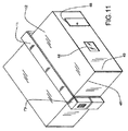
モジュラーユニット10は、アルミニウムの押出物から成る堅い中心コアフレーム19を有する。フレーム(図3)は、一緒に溶接されて長方形を形成する水平な押出物56と垂直な押出物27とを有し、2つのそのような長方形は、クロス梁28押出物と共に溶接される。その結果は、予期されたものよりも高い強度を有する箱梁フレームである。ベース部分26、屋根部分25および端区分20、13を取り付けることによって、コアは、屋根区分25、床区分22、外壁区分21および側壁区分24に対する支持を提供し、その屋根区分25、床区分22、外壁区分21および側壁区分24は、コアに付着させられ、かつ広げられることにより内側空間を形成する。コアの端に(図1)、空気調節ユニット17が取り付けられ、その空気調節ユニット17は、冷やされたまたは熱せられた空気の両方を内側空間に提供し得る。蓄電キャビネット18がさらに、電力分配のために必要とされる任意の電気装置に提供される。他の構成において、コアのもう一端に、保管キャビネットが付けられ得る。この閉じた構成において(図1)、ユニット10は、リフトよって容易に移送され得るか、またはベース部分の各角に車輪を取り付けることによって容易に動かされ得る。
The modular unit 10 has a rigid
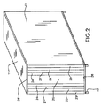
図2は、モジュラーユニットの露出した端を示す。中心コア端部分20が示され、各側面において、複数のパネルが、中心コア端部分20に隣接し、その複数のパネルは、広げられることによりモジュラーユニットを展開された使用可能なシェルターに変形させる。最も外側のパネル23は、広がる屋根区分であり、次が床区分22、それから外壁区分21である。最も内側の区分は、側壁区分24である。屋根23、床22、外壁21および側壁24区分は、固定位置まで外に回転することにより内側空間を生成し得る。屋根、床、外壁および側壁区分は、複合パネルである。
FIG. 2 shows the exposed end of the modular unit. A central
好ましい中心コア区分(図3)は、水平な押し出されたアルミニウム梁28と共に溶接されることにより箱梁構造を生成する、押し出されたアルミニウム垂直梁27の堅いフレームであり、その箱梁構造は、高い強度を提供するが、重量が軽い。しかし、堅いフレームは、当業者に既知の種々の形態において構成されることにより、堅い構造を提供し得る。
A preferred central core section (FIG. 3) is a rigid frame of extruded aluminum
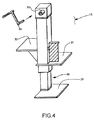
図1は、モジュラーユニット10の角の各々における支持部15を示す。図4は、支持部15の構成を詳細に示す。支持部15は、ベースプレート29、支持脚30、支持プレート32および31から成ることによりコア構造を保持し、ソケット33内に挿入され得るレンチ34は、支持脚30のつめ車またはクランクを回すことを可能にし、素早いだけでなく容易なモジュラーユニットの高さおよび水平調節を可能にする。これは好ましい実施形態であるが、数多くの他の既知のメカニズム(たとえば、ボルトが突き通されることにより種々の不連続な設定における高さを設定する複数孔支持物、または高さを調節するために、ねじを切った棒を回転させることによって調節され得る、ねじを切った棒が接続されたプレート)が、使用され得る。
FIG. 1 shows a
モジュラーユニットを用いることが所望される場合、ユニット10は、ひらけた場所に配置される。ひらけた場所は、安定化された地面、または任意の補強されたベース(たとえば、砂利、コンクリートまたはアスファルト)上であり得、ユニット10は、支持部15を使用して水平にされことにより、適切な高さを設定し、すべての角は水平にされる。支持梁37は、図5に示されるように、モジュラーユニットのベース部分に沿って設けられた受け部36に挿入される。梁37のもう一端に、ねじを切った棒を溶接されたプレートがあり、そのねじを切った棒は、梁37の端にねじ込まれる。プレート40は、すべての梁37が水平にされるまで回転させられ、それによって、ユニット10の外壁表面12と直角をなす。
If it is desired to use a modular unit, the unit 10 is placed in the open position. The open location can be on a stabilized ground, or on any reinforced base (eg gravel, concrete or asphalt), and the unit 10 can be properly leveled using a
図6は、開けられているモジュラーユニット10を示す。外側の屋根パネル区分23は、ユニット本体から離れる方へおよそ90度外に回転させられる。2つのばね上げダンパー41は、図6に示されるように、屋根区分23に支持を提供することを補助する。コア区分の頂部の外側部分11および屋根区分23の外側表面12は、好ましくは、ユニットの使用に応じて、屋根葺き材料または他の材料で覆われる。
FIG. 6 shows the modular unit 10 being opened. The outer
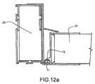
図7は、屋根区分23が引き続き開くことを示し、開くことは、結合した床22および外壁21区分が、支持床梁37上の置く位置まで外へ回転させられることを可能にする。床区分22が所定の場所に置かれた状態で、外壁区分21は、直立するように回転させられて、上の縁61は、屋根区分23の外側の縁62と連結する。縁61と62との相互連結の詳細は、図12bに見られる。追加の連結は、外壁の縁に沿って設けられた従来の固定メカニズムを用いて実現され得る。屋根の縁62が外壁の縁61に付けられた状態で、側壁24は、図9に示されるように広げられ、その側壁24の縁46および47は、屋根の縁48および外壁の縁49と接続し得る。
FIG. 7 shows that the
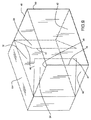
図10は、モジュラーユニット10の1つの側面の展開された構成を示し、図11においてモジュラーユニットは、完全に開かれている。屋根、外壁および側壁区分は、絶縁された複合パネルであり、その絶縁された複合パネルは、軽量のさびない材料である外側パネルと、熱に耐性がある材料の中心コアと、内側パネルとから成り、これらすべてが一緒に接着させられている。好ましい形態において、内側および外側パネルは、発泡スチロールフォームまたはポリウレタンフォームの内側コアを有するアルミニウムである。絶縁されたパネルの使用は、温度の安定を提供し、中心コア区分は、空気調節/換気ユニット17を用いて、冷房と暖房との両方を可住内側空間に直接提供する。パネルの縁は、金属押出物を用いてキャップされ、その金属押出物は、パネルの縁間の接続機能を、図8に示されるようなベース部分と床区分との間の接続部64、または頂部部分と屋根区分との間の接続部63、または床区分と外壁区分との間の接続部65において見られるような回転ヒンジ接続部、または図8に見られるような屋根区分の縁62と外壁区分の縁61との間の連結部のどちらかに提供する。
FIG. 10 shows the unfolded configuration of one side of the modular unit 10, in which the modular unit is fully open. The roof, outer wall and side wall sections are insulated composite panels, which consist of an outer panel that is a lightweight, non-rusting material, a central core of heat resistant material, and an inner panel. All of these are glued together. In a preferred form, the inner and outer panels are aluminum with a foamed polystyrene or polyurethane foam inner core. The use of insulated panels provides temperature stability, and the central core section uses the air conditioning /
図12aは、典型的な回転接続を示し、頂部部分断面25および屋根区分断面23は、構成要素の断面の押出物の交わりによって接続される。2つの金属押出物キャップは、屋根頂部キャップの押出物71の一部と屋根区分キャップ押出物72の一部との円形の嵌合において互いのまわりで回転することによって連結し、押出物を一緒に固定し、押出物間に密閉を生成する。その結果は、予期されたものよりも強い構造を生成するための押出物とパネルとの固定である。さらに、接続部は、継ぎ目を通した水および風の侵入を妨げる。
FIG. 12a shows a typical rotational connection, where the top
他の構成において、さねと溝との接続部に、シーラントが、接続部の外側に配置されることにより、水および風の侵入を防ぎ得る。好ましくは、シーラントが使用される場合、ユニットを隠すときにシーラントのより容易な除去を可能にするために、シーラントは、区分間の接続がなされたあとで配置されるべきである。 In another configuration, the sealant is disposed outside the connection portion at the connection portion between the tongue and the groove, thereby preventing water and wind from entering. Preferably, if a sealant is used, the sealant should be placed after the connection between the sections has been made to allow easier removal of the sealant when hiding the unit.
図12bは、屋根区分25の外側の縁62と外壁21の上の縁61との間に使用される連結接続を示し、その連結接続は、外壁区分または屋根区分の縁と側壁区分との接続部によっても使用され得る。このさね74と溝73との接続連結は、実質的に連続的な接触状態であり、その連続的な接触状態は、予期されたものよりも強い開いた構造のフレームに、構造上の無欠を提供する。さらに、さねと溝との接続部は、水および空気の侵入を防ぐ。
FIG. 12 b shows the connecting connection used between the
図8、10および11に示される構成において、電気、データおよび配管サービスのために壁および内側コアに予備配線をするだけでなく、1つ以上の窓44または戸45が、外壁区分または側壁区分において提供され得る。他の構成において、モジュラーユニットは、内側の仕切りを後ほど設置させることにより、ユニットの使用が要求するように調節され得る。簡易台所モジュールおよび浴室モジュールは、それらの機能が所望される場合、ユニットに追加され得る。
In the configurations shown in FIGS. 8, 10 and 11, one or
モジュラーユニットが、事前設置されたすべての必要とされる構成要素を含むので、2人の最小限訓練されたクルーは、モジュラーユニットを水平にし、かつ完全に展開し、クルーの技術および経験に応じて、15〜30分の間にモジュラーユニットを使用可能にし得る。 Since the modular unit includes all the pre-installed required components, two minimally trained crews level and fully deploy the modular unit, depending on the crew's skill and experience The modular unit can be made available for 15-30 minutes.
他の構成において、モジュラーユニットは、堅い中心コア区分の各端に車輪を設けられ、その車輪は、ユニットが、倉庫までおよび倉庫からトラック積荷場まで特殊な装置なしに便利に動かされること、または開く前に所望の位置に移動させられることを可能にする。種々の例示的な局面および実施形態が、本明細書中に示され、または論じられてきたが、用いられ得る他の改変は、本発明の範囲内にある。したがって、本発明は、示された構成に制限されず、添付の特許請求の範囲の精神および範囲の範囲内にあるすべての注目の改変または変種を包含することが意図されている。 In other configurations, the modular unit is provided with a wheel at each end of the rigid central core section, the wheel being conveniently moved without special equipment from the warehouse to the warehouse and from the warehouse to the truck loading area, or Allows to be moved to the desired position before opening. While various exemplary aspects and embodiments have been shown or discussed herein, other modifications that can be used are within the scope of the invention. Accordingly, the present invention is not intended to be limited to the arrangements shown, but is intended to embrace all noted modifications or variations that fall within the spirit and scope of the appended claims.
さらに、用語「include」が、詳細な説明または特許請求の範囲のどちらかにおいて使用されるかぎり、そのような用語は、「comprising」が、特許請求の範囲において慣習的な言葉として用いられる場合に解釈されるように、用語「comprising」と同様の態様で、包括的であることが意図されている。 Further, as long as the term “include” is used in either the detailed description or the claims, such terms are used where “comprising” is used as a customary term in the claims. As interpreted, it is intended to be inclusive in a manner similar to the term “comprising”.
Claims (23)
堅い長方形のコアであって、該コアは、
ベース部分と、
頂部部分と、
第一および第二の端区分であって、該端区分は、堅い溶接されたアルミニウム押出物フレーム構造に付けられ、該端区分は、該ベース部分および頂部部分の向かい合う端に付けられている、第一および第二の端区分と
を含む堅い長方形のコアと、
該堅い長方形のコアと一体をなす折り畳み可能な長方形のコンテナ部分であって、該折り畳み可能な長方形のコンテナ部分は、
第一および第二の屋根区分と、
第一および第二の床区分と、
第一および第二の外壁区分と、
第一および第二の側壁区分と
を含み、該第一および第二の側壁区分は、互いにまたは該コアに接続され、該接続されることは、該区分が、広げられることにより、該コアに隣接した囲まれた空間を形成することを可能にする、折り畳み可能な長方形のコンテナ部分と、
押し出された金属区分の複数の区分キャップであって、該押し出された金属区分の複数の区分キャップは、該キャップが取り付けられる該屋根、床、外壁および側壁区分の細長い縁に付けられ、該キャップは、該キャップが取り付けられる該屋根、床、外壁および側壁区分の該細長い縁の長さとほぼ同じであり、該キャップが取り付けられるのは、該区分および/またはコアが互いに隣接している場所であり、該押し出された金属キャップは、連続的な接触状態にあるように互いに嵌合し、2つの隣接する区分またはコアと区分との間において、およそ90度の該接続された区分の回転運動を可能にし、隣接する区分が回転させられる場合、2つの押出物は、互いの周りで回転し、一緒に固定し、押出物間に密閉を生成する、押し出された金属区分の複数の区分キャップと、
押し出された金属区分の複数のキャップであって、該押し出された金属区分の複数のキャップは、該キャップが取り付けられる該屋根、床、外壁および側壁区分の該細長い縁に付けられ、該キャップは、該キャップが取り付けられる該屋根、床、外壁および側壁区分の該細長い縁の長さとほぼ同じであり、該キャップが取り付けられるのは、該区分が回転しないように互いに接続される場所であり、該押し出された金属キャップは、実質的に連続的な接触状態にあるように、および緊密に取り付けられるように、さねと溝との接続部において互いに嵌合する、押し出された金属区分の複数のキャップと、
一端に水平プレートを有し、反対の端を該コアの該ベース部分におけるスロットにはめ込む複数の床支持梁と、
該ベース部分の各角において該コアを水平にする手段と
を含み、該コアは、水平にされることが可能であり、該床梁は、配置されて水平にされ、該屋根区分は、上へ回転させられることにより、該床区分および外壁区分が、該床区分が該床梁上に置かれるように、下へ回転させられることを可能にし、該外壁区分は、該外壁区分の該外側の縁が該屋根区分の該外側の縁と接続するように、回転させられて該床区分と直角をなし、該側壁区分は、該側壁区分が該屋根および外壁区分と接続するように、外へ回転させられ、それによって、囲まれた使用可能空間を生成する、
移送可能な折り畳み可能構造。 A foldable structure that is transportable, the structure comprising:
A rigid rectangular core, which is
A base part,
A top portion;
First and second end sections, the end sections being attached to a rigid welded aluminum extrudate frame structure, the end sections being attached to opposite ends of the base portion and the top portion; A rigid rectangular core including first and second end sections; and
A collapsible rectangular container part integral with the rigid rectangular core, wherein the collapsible rectangular container part comprises:
A first and second roof section;
A first and second floor section;
First and second outer wall sections;
First and second side wall sections, wherein the first and second side wall sections are connected to each other or to the core, the connecting to the core by expanding the section. A collapsible rectangular container portion that allows to form an adjacent enclosed space;
A plurality of segmented caps of the extruded metal segment, wherein the plurality of segmented caps of the extruded metal segment are attached to the elongate edges of the roof, floor, outer wall and side wall segments to which the cap is attached, Is approximately the same as the length of the elongate edge of the roof, floor, outer wall and side wall sections to which the cap is attached, and the cap is attached where the sections and / or cores are adjacent to each other. The extruded metal caps fit together so that they are in continuous contact, and the connected segment rotational movement of approximately 90 degrees between two adjacent segments or cores and segments The two extrudates are rotated around each other and secured together, creating a seal between the extrudates, when adjacent sections are rotated And a plurality of sections cap segment,
A plurality of caps of extruded metal sections, wherein the caps of the extruded metal sections are attached to the elongated edges of the roof, floor, outer wall and side wall sections to which the caps are attached, the caps Approximately the same as the length of the elongate edge of the roof, floor, exterior wall and side wall sections to which the cap is attached, and where the cap is attached is where the sections are connected to each other so that they do not rotate; The extruded metal cap is a plurality of extruded metal sections that fit together at the tongue and groove connection so that they are in substantially continuous contact and are closely attached. And the cap
A plurality of floor support beams having a horizontal plate at one end and fitting the opposite end into a slot in the base portion of the core;
Means for leveling the core at each corner of the base portion, the core can be leveled, the floor beams are placed and leveled, and the roof section is To allow the floor section and the outer wall section to be rotated down so that the floor section is placed on the floor beam, the outer wall section being outside of the outer wall section. Rotated so as to connect the outer edge of the roof section with the outer edge of the roof section and perpendicular to the floor section, the side wall section being connected to the roof and the outer wall section so that the side wall section is connected to the roof and the outer wall section. To create an enclosed usable space,
Transportable foldable structure.
Applications Claiming Priority (3)
| Application Number | Priority Date | Filing Date | Title |
|---|---|---|---|
| US201161510564P | 2011-07-22 | 2011-07-22 | |
| US61/510,564 | 2011-07-22 | ||
| PCT/US2012/047631 WO2013016202A2 (en) | 2011-07-22 | 2012-07-20 | Collapsible portable shelter unit |
Related Child Applications (1)
| Application Number | Title | Priority Date | Filing Date |
|---|---|---|---|
| JP2015005779A Division JP2015108286A (en) | 2011-07-22 | 2015-01-15 | Collapsible portable shelter unit |
Publications (1)
| Publication Number | Publication Date |
|---|---|
| JP2014507585A true JP2014507585A (en) | 2014-03-27 |
Family
ID=47554907
Family Applications (2)
| Application Number | Title | Priority Date | Filing Date |
|---|---|---|---|
| JP2013552745A Pending JP2014507585A (en) | 2011-07-22 | 2012-07-20 | Foldable mobile shelter unit |
| JP2015005779A Pending JP2015108286A (en) | 2011-07-22 | 2015-01-15 | Collapsible portable shelter unit |
Family Applications After (1)
| Application Number | Title | Priority Date | Filing Date |
|---|---|---|---|
| JP2015005779A Pending JP2015108286A (en) | 2011-07-22 | 2015-01-15 | Collapsible portable shelter unit |
Country Status (3)
| Country | Link |
|---|---|
| US (1) | US9187894B2 (en) |
| JP (2) | JP2014507585A (en) |
| WO (1) | WO2013016202A2 (en) |
Cited By (1)
| Publication number | Priority date | Publication date | Assignee | Title |
|---|---|---|---|---|
| JP2021107666A (en) * | 2019-12-27 | 2021-07-29 | 株式会社中村製作所 | Resting shelter |
Families Citing this family (24)
| Publication number | Priority date | Publication date | Assignee | Title |
|---|---|---|---|---|
| MX2011006850A (en) | 2008-12-23 | 2011-08-15 | Xoma Technology Ltd | Flexible manufacturing system. |
| US9795957B2 (en) * | 2009-08-16 | 2017-10-24 | G-Con Manufacturing, Inc. | Modular, self-contained, mobile clean room |
| KR20120054634A (en) | 2009-08-16 | 2012-05-30 | 지-콘, 엘엘씨 | Modular, self-contained, mobile clean room |
| US9085890B2 (en) * | 2011-05-05 | 2015-07-21 | Rapid Fabrications IP LLC | Collapsible transportable structures and related systems and methods |
| US9062486B2 (en) | 2012-03-02 | 2015-06-23 | Vantem Modular, Llc | Interconnection system for panel assemblies |
| CN103306373B (en) * | 2013-07-02 | 2015-06-24 | 郑州红宇专用汽车有限责任公司 | Unit modular folding mobile house suitable for combined use |
| CN105723036B (en) * | 2013-10-14 | 2019-12-27 | 吉康制造有限公司 | Unit for connecting modular moving spaces |
| GB2532368B (en) * | 2013-11-06 | 2018-07-18 | Extremis Tech Ltd | Emergency shelter |
| USD820469S1 (en) * | 2014-11-07 | 2018-06-12 | Extremis Technology Ltd | Deployable building |
| US10738459B2 (en) | 2017-04-28 | 2020-08-11 | Big 6, LLP | Vault for active shooters and tornadoes |
| SK8396Y1 (en) * | 2017-06-27 | 2019-03-01 | Zepelin S R O | Container folding shelter |
| US10590671B1 (en) * | 2017-09-26 | 2020-03-17 | U.S. Government As Represented By The Secretary Of The Army | Configurable modular shelter system |
| CN207646881U (en) * | 2017-12-14 | 2018-07-24 | 江苏跃发建设工程有限公司 | Foldable ultralight steel movable plank house |
| US20190337582A1 (en) * | 2018-05-04 | 2019-11-07 | Robin Whincup | Mobile obstacle courses |
| CN109057403B (en) * | 2018-07-17 | 2020-12-01 | 温州莱益机械有限公司 | Municipal construction lodging canopy |
| AU2019336329B2 (en) | 2018-09-05 | 2025-09-11 | Matt James Clifton | A collapsible dwelling |
| RU2714030C1 (en) * | 2019-01-13 | 2020-02-11 | Дмитрий Геннадьевич Касиев | Mobile modular house |
| BR112022002854B1 (en) | 2019-08-15 | 2023-01-31 | G-Con Manufacturing, Inc | MODULAR CONSTRUCTION APPLIANCE FOR PHARMACEUTICAL CLEAN ROOM MANUFACTURING AND METHOD OF ASSEMBLING A MODULAR CLEAN ROOM APPLIANCE FOR PHARMACEUTICAL CLEAN ROOM MANUFACTURING |
| EP3912649B1 (en) * | 2020-05-19 | 2023-10-25 | SEIWO Technik GmbH | Modular protective area and pass-through for same |
| KR102432161B1 (en) * | 2020-08-07 | 2022-08-12 | 한양대학교 산학협력단 | Collapsible and movable installation type medical booth |
| US11492795B2 (en) | 2020-08-31 | 2022-11-08 | G-Con Manufacturing, Inc. | Ballroom-style cleanroom assembled from modular buildings |
| WO2022183296A1 (en) * | 2021-03-03 | 2022-09-09 | Rohe Homes Ltd. | Systems and methods for manufacturing and deploying modular buildings |
| US20220396947A1 (en) * | 2021-03-30 | 2022-12-15 | John D. Moore | Compactible and foldable Drop shop building |
| CN115306033B (en) * | 2022-08-10 | 2024-07-30 | 中建铁路投资建设集团有限公司 | Shelter capable of being spliced rapidly for hospital temporarily |
Citations (4)
| Publication number | Priority date | Publication date | Assignee | Title |
|---|---|---|---|---|
| JPS53162505U (en) * | 1977-05-26 | 1978-12-19 | ||
| US20070245637A1 (en) * | 2006-04-03 | 2007-10-25 | Ronald Chester Czyznikiewicz | Shelter pac |
| JP2009510282A (en) * | 2005-09-26 | 2009-03-12 | ウェザーヘイブン リソーシズ リミテッド | Foldable modular shelter for container transport |
| JP2010265746A (en) * | 2009-05-15 | 2010-11-25 | Indian Inst Of Technology Delhi | Hinge joint system |
Family Cites Families (28)
| Publication number | Priority date | Publication date | Assignee | Title |
|---|---|---|---|---|
| US1498173A (en) * | 1922-02-11 | 1924-06-17 | George L Kelley | Building structure |
| US3585768A (en) * | 1968-09-05 | 1971-06-22 | Louis H Klein | Structural posts and panel connectors including panel structure |
| US3818662A (en) * | 1970-11-19 | 1974-06-25 | Perfect Module Systems | Wall retainer |
| EP0127070A3 (en) | 1983-05-31 | 1985-10-02 | VOLANI EBS S.p.A. | A transportable inhabitative unit of alterable capacity |
| US4667580A (en) * | 1984-07-19 | 1987-05-26 | Wetzel Lawrence E | Clean room module |
| US4633626A (en) | 1984-12-03 | 1987-01-06 | The Budd Company | Knock-down extendible shelter |
| US5345730A (en) | 1985-05-30 | 1994-09-13 | Jurgensen Bruce A | Expandable structure and sequence of expansion |
| US4689924A (en) * | 1985-05-30 | 1987-09-01 | Jurgensen Bruce A | Expandable structure and sequence of expansion |
| US4676039A (en) * | 1986-01-17 | 1987-06-30 | Gittle Leiter | Quick assembly and knockdown building structure |
| CA2100845C (en) | 1993-07-19 | 1998-12-15 | Brian Johnson | Collapsible portable containerized shelter |
| US5461832A (en) | 1994-05-09 | 1995-10-31 | Smith; Gene A. | Transportable foldable building and method of erecting a transportable foldable building |
| US5596844A (en) * | 1995-02-03 | 1997-01-28 | Kalinowski; Juan R. | Foldable portable building |
| GB9503228D0 (en) * | 1995-02-18 | 1995-04-05 | Dyer David C | Modular structures and seals therefor |
| US5966956A (en) | 1996-11-20 | 1999-10-19 | Shelter Technologies, Inc. | Portable refrigerated storage unit |
| EP1054113A1 (en) | 1999-05-19 | 2000-11-22 | Reltec Italia S.p.A | Compact shelter |
| US6434895B1 (en) | 1999-09-09 | 2002-08-20 | Bendon, L.L.C. | Foldable trailerable building |
| US20020116878A1 (en) | 2000-09-29 | 2002-08-29 | Ciotti Theodore T. | Containerized habitable structures |
| US6948280B2 (en) * | 2002-01-30 | 2005-09-27 | Dave Marcinkowski | Assembleable and towable/trailerable ice fishing shanty/hunting blind |
| US20050193643A1 (en) * | 2002-05-08 | 2005-09-08 | Pettus Daryl O. | Modular containment unit |
| IL151244A (en) * | 2002-08-14 | 2006-10-31 | Chagim Nechalim Ind Ltd | Panel for modular construction |
| US20040194396A1 (en) * | 2003-04-01 | 2004-10-07 | Vincent Shanni | Prefabricated folding structure having interlocking metal beams |
| US7658037B2 (en) * | 2003-12-03 | 2010-02-09 | Eads Deutschland Gmbh | Variable volume container unit hoisting device for lowering and raising a telescopable expansion element |
| US7966775B2 (en) | 2004-10-04 | 2011-06-28 | Global Engineering Marketing Llc | Convertible hard side shelter |
| CN100389243C (en) * | 2004-12-20 | 2008-05-21 | 厦门人和跨过进出口有限公司 | movable buildings |
| WO2008005307A2 (en) * | 2006-07-01 | 2008-01-10 | Gregory Burns | Panel structure |
| US20080236055A1 (en) * | 2007-03-30 | 2008-10-02 | Laprise Daniel | Foldable habitation |
| US20100024351A1 (en) * | 2008-07-29 | 2010-02-04 | Green Horizon Manufacturing Llc | Method of deploying and redeploying a prefabricated structure |
| US8555559B2 (en) * | 2011-05-11 | 2013-10-15 | Vincent J. Digregory | Foldable transportable structure |
-
2012
- 2012-07-20 JP JP2013552745A patent/JP2014507585A/en active Pending
- 2012-07-20 WO PCT/US2012/047631 patent/WO2013016202A2/en not_active Ceased
- 2012-07-20 US US13/554,341 patent/US9187894B2/en not_active Expired - Fee Related
-
2015
- 2015-01-15 JP JP2015005779A patent/JP2015108286A/en active Pending
Patent Citations (4)
| Publication number | Priority date | Publication date | Assignee | Title |
|---|---|---|---|---|
| JPS53162505U (en) * | 1977-05-26 | 1978-12-19 | ||
| JP2009510282A (en) * | 2005-09-26 | 2009-03-12 | ウェザーヘイブン リソーシズ リミテッド | Foldable modular shelter for container transport |
| US20070245637A1 (en) * | 2006-04-03 | 2007-10-25 | Ronald Chester Czyznikiewicz | Shelter pac |
| JP2010265746A (en) * | 2009-05-15 | 2010-11-25 | Indian Inst Of Technology Delhi | Hinge joint system |
Cited By (2)
| Publication number | Priority date | Publication date | Assignee | Title |
|---|---|---|---|---|
| JP2021107666A (en) * | 2019-12-27 | 2021-07-29 | 株式会社中村製作所 | Resting shelter |
| JP7580915B2 (en) | 2019-12-27 | 2024-11-12 | 株式会社中村製作所 | Rest shelter |
Also Published As
| Publication number | Publication date |
|---|---|
| US20130019913A1 (en) | 2013-01-24 |
| JP2015108286A (en) | 2015-06-11 |
| US9187894B2 (en) | 2015-11-17 |
| WO2013016202A2 (en) | 2013-01-31 |
| WO2013016202A3 (en) | 2013-05-02 |
Similar Documents
| Publication | Publication Date | Title |
|---|---|---|
| JP2014507585A (en) | Foldable mobile shelter unit | |
| US8707634B2 (en) | Collapsible modular building with canvas seams | |
| US10648169B2 (en) | Packaged container housing structure and construction method | |
| AU2012247151B2 (en) | Modular living unit | |
| US20140144088A1 (en) | Erectable housing structure with a shipping container configuration | |
| US6712414B2 (en) | Mobile, expandable structure, assembly support system | |
| JP5873086B2 (en) | Folding construction unit | |
| US7100332B2 (en) | Unfolding modular building system | |
| US11473292B2 (en) | Expandable container shelter | |
| US20100192481A1 (en) | Prefabricated container house | |
| US10415263B2 (en) | Packaged container housing structure and construction method | |
| US20070144078A1 (en) | Expandable container | |
| JP2014508873A (en) | Building structure | |
| US10343586B2 (en) | Expandable vehicle shelter system and method | |
| US8550528B2 (en) | Expanding mobile utility structure | |
| EP1975329B1 (en) | Foldable habitation | |
| KR102122390B1 (en) | Movable simple house | |
| RU141658U1 (en) | TRANSFORMABLE STRUCTURE WITH VARIABLE INTERNAL VOLUME | |
| RU2469155C2 (en) | Folding fortification structure | |
| AU2012101412A4 (en) | An Expandable Cargo Container | |
| HK1194782B (en) | Modular living unit | |
| ITPI20100016U1 (en) | PREFAFFRICATED PARALLELEPIPED STRUCTURE EXTENDABLE READY TO USE BUT OF SAGOMA INITIALLY STANDARD TRANSPORTABLE ON ROAD, RAILWAY, AIRCRAFT, MARITIME CARRIERS, DESIGNED AND BUILT WITH PROPER MATERIALS, CONGEGNI, DEVICES AND CERNIERS |
Legal Events
| Date | Code | Title | Description |
|---|---|---|---|
| A977 | Report on retrieval |
Free format text: JAPANESE INTERMEDIATE CODE: A971007 Effective date: 20140710 |
|
| A131 | Notification of reasons for refusal |
Free format text: JAPANESE INTERMEDIATE CODE: A131 Effective date: 20140715 |
|
| A601 | Written request for extension of time |
Free format text: JAPANESE INTERMEDIATE CODE: A601 Effective date: 20141014 |
|
| A602 | Written permission of extension of time |
Free format text: JAPANESE INTERMEDIATE CODE: A602 Effective date: 20141021 |
|
| A601 | Written request for extension of time |
Free format text: JAPANESE INTERMEDIATE CODE: A601 Effective date: 20141029 |
|
| A602 | Written permission of extension of time |
Free format text: JAPANESE INTERMEDIATE CODE: A602 Effective date: 20141106 |
|
| A601 | Written request for extension of time |
Free format text: JAPANESE INTERMEDIATE CODE: A601 Effective date: 20141212 |
|
| A602 | Written permission of extension of time |
Free format text: JAPANESE INTERMEDIATE CODE: A602 Effective date: 20141219 |
|
| A521 | Request for written amendment filed |
Free format text: JAPANESE INTERMEDIATE CODE: A523 Effective date: 20150115 |
|
| A131 | Notification of reasons for refusal |
Free format text: JAPANESE INTERMEDIATE CODE: A131 Effective date: 20150428 |
|
| A601 | Written request for extension of time |
Free format text: JAPANESE INTERMEDIATE CODE: A601 Effective date: 20150727 |
|
| A601 | Written request for extension of time |
Free format text: JAPANESE INTERMEDIATE CODE: A601 Effective date: 20150827 |
|
| A02 | Decision of refusal |
Free format text: JAPANESE INTERMEDIATE CODE: A02 Effective date: 20151124 |