JP2014016018A - Speed reduction mechanism and motor rotational force transmission device including the same - Google Patents
Speed reduction mechanism and motor rotational force transmission device including the same Download PDFInfo
- Publication number
- JP2014016018A JP2014016018A JP2012155818A JP2012155818A JP2014016018A JP 2014016018 A JP2014016018 A JP 2014016018A JP 2012155818 A JP2012155818 A JP 2012155818A JP 2012155818 A JP2012155818 A JP 2012155818A JP 2014016018 A JP2014016018 A JP 2014016018A
- Authority
- JP
- Japan
- Prior art keywords
- axis
- rotation force
- output
- motor
- speed reduction
- Prior art date
- Legal status (The legal status is an assumption and is not a legal conclusion. Google has not performed a legal analysis and makes no representation as to the accuracy of the status listed.)
- Granted
Links
Images



Classifications
-
- F—MECHANICAL ENGINEERING; LIGHTING; HEATING; WEAPONS; BLASTING
- F16—ENGINEERING ELEMENTS AND UNITS; GENERAL MEASURES FOR PRODUCING AND MAINTAINING EFFECTIVE FUNCTIONING OF MACHINES OR INSTALLATIONS; THERMAL INSULATION IN GENERAL
- F16H—GEARING
- F16H1/00—Toothed gearings for conveying rotary motion
- F16H1/28—Toothed gearings for conveying rotary motion with gears having orbital motion
- F16H1/32—Toothed gearings for conveying rotary motion with gears having orbital motion in which the central axis of the gearing lies inside the periphery of an orbital gear
-
- B—PERFORMING OPERATIONS; TRANSPORTING
- B60—VEHICLES IN GENERAL
- B60K—ARRANGEMENT OR MOUNTING OF PROPULSION UNITS OR OF TRANSMISSIONS IN VEHICLES; ARRANGEMENT OR MOUNTING OF PLURAL DIVERSE PRIME-MOVERS IN VEHICLES; AUXILIARY DRIVES FOR VEHICLES; INSTRUMENTATION OR DASHBOARDS FOR VEHICLES; ARRANGEMENTS IN CONNECTION WITH COOLING, AIR INTAKE, GAS EXHAUST OR FUEL SUPPLY OF PROPULSION UNITS IN VEHICLES
- B60K1/00—Arrangement or mounting of electrical propulsion units
-
- B—PERFORMING OPERATIONS; TRANSPORTING
- B60—VEHICLES IN GENERAL
- B60K—ARRANGEMENT OR MOUNTING OF PROPULSION UNITS OR OF TRANSMISSIONS IN VEHICLES; ARRANGEMENT OR MOUNTING OF PLURAL DIVERSE PRIME-MOVERS IN VEHICLES; AUXILIARY DRIVES FOR VEHICLES; INSTRUMENTATION OR DASHBOARDS FOR VEHICLES; ARRANGEMENTS IN CONNECTION WITH COOLING, AIR INTAKE, GAS EXHAUST OR FUEL SUPPLY OF PROPULSION UNITS IN VEHICLES
- B60K17/00—Arrangement or mounting of transmissions in vehicles
- B60K17/04—Arrangement or mounting of transmissions in vehicles characterised by arrangement, location or kind of gearing
-
- B—PERFORMING OPERATIONS; TRANSPORTING
- B60—VEHICLES IN GENERAL
- B60K—ARRANGEMENT OR MOUNTING OF PROPULSION UNITS OR OF TRANSMISSIONS IN VEHICLES; ARRANGEMENT OR MOUNTING OF PLURAL DIVERSE PRIME-MOVERS IN VEHICLES; AUXILIARY DRIVES FOR VEHICLES; INSTRUMENTATION OR DASHBOARDS FOR VEHICLES; ARRANGEMENTS IN CONNECTION WITH COOLING, AIR INTAKE, GAS EXHAUST OR FUEL SUPPLY OF PROPULSION UNITS IN VEHICLES
- B60K17/00—Arrangement or mounting of transmissions in vehicles
- B60K17/34—Arrangement or mounting of transmissions in vehicles for driving both front and rear wheels, e.g. four wheel drive vehicles
- B60K17/356—Arrangement or mounting of transmissions in vehicles for driving both front and rear wheels, e.g. four wheel drive vehicles having fluid or electric motor, for driving one or more wheels
-
- F—MECHANICAL ENGINEERING; LIGHTING; HEATING; WEAPONS; BLASTING
- F16—ENGINEERING ELEMENTS AND UNITS; GENERAL MEASURES FOR PRODUCING AND MAINTAINING EFFECTIVE FUNCTIONING OF MACHINES OR INSTALLATIONS; THERMAL INSULATION IN GENERAL
- F16H—GEARING
- F16H57/00—General details of gearing
- F16H57/02—Gearboxes; Mounting gearing therein
- F16H57/021—Shaft support structures, e.g. partition walls, bearing eyes, casing walls or covers with bearings
-
- B—PERFORMING OPERATIONS; TRANSPORTING
- B60—VEHICLES IN GENERAL
- B60K—ARRANGEMENT OR MOUNTING OF PROPULSION UNITS OR OF TRANSMISSIONS IN VEHICLES; ARRANGEMENT OR MOUNTING OF PLURAL DIVERSE PRIME-MOVERS IN VEHICLES; AUXILIARY DRIVES FOR VEHICLES; INSTRUMENTATION OR DASHBOARDS FOR VEHICLES; ARRANGEMENTS IN CONNECTION WITH COOLING, AIR INTAKE, GAS EXHAUST OR FUEL SUPPLY OF PROPULSION UNITS IN VEHICLES
- B60K1/00—Arrangement or mounting of electrical propulsion units
- B60K2001/001—Arrangement or mounting of electrical propulsion units one motor mounted on a propulsion axle for rotating right and left wheels of this axle
-
- F—MECHANICAL ENGINEERING; LIGHTING; HEATING; WEAPONS; BLASTING
- F16—ENGINEERING ELEMENTS AND UNITS; GENERAL MEASURES FOR PRODUCING AND MAINTAINING EFFECTIVE FUNCTIONING OF MACHINES OR INSTALLATIONS; THERMAL INSULATION IN GENERAL
- F16H—GEARING
- F16H1/00—Toothed gearings for conveying rotary motion
- F16H1/28—Toothed gearings for conveying rotary motion with gears having orbital motion
- F16H1/32—Toothed gearings for conveying rotary motion with gears having orbital motion in which the central axis of the gearing lies inside the periphery of an orbital gear
- F16H2001/325—Toothed gearings for conveying rotary motion with gears having orbital motion in which the central axis of the gearing lies inside the periphery of an orbital gear comprising a carrier with pins guiding at least one orbital gear with circular holes
-
- F—MECHANICAL ENGINEERING; LIGHTING; HEATING; WEAPONS; BLASTING
- F16—ENGINEERING ELEMENTS AND UNITS; GENERAL MEASURES FOR PRODUCING AND MAINTAINING EFFECTIVE FUNCTIONING OF MACHINES OR INSTALLATIONS; THERMAL INSULATION IN GENERAL
- F16H—GEARING
- F16H57/00—General details of gearing
- F16H57/02—Gearboxes; Mounting gearing therein
- F16H2057/02013—Extension units for gearboxes, e.g. additional units attached to a main gear
-
- F—MECHANICAL ENGINEERING; LIGHTING; HEATING; WEAPONS; BLASTING
- F16—ENGINEERING ELEMENTS AND UNITS; GENERAL MEASURES FOR PRODUCING AND MAINTAINING EFFECTIVE FUNCTIONING OF MACHINES OR INSTALLATIONS; THERMAL INSULATION IN GENERAL
- F16H—GEARING
- F16H48/00—Differential gearings
- F16H48/20—Arrangements for suppressing or influencing the differential action, e.g. locking devices
- F16H48/30—Arrangements for suppressing or influencing the differential action, e.g. locking devices using externally-actuatable means
Landscapes
- Engineering & Computer Science (AREA)
- Mechanical Engineering (AREA)
- General Engineering & Computer Science (AREA)
- Chemical & Material Sciences (AREA)
- Combustion & Propulsion (AREA)
- Transportation (AREA)
- Retarders (AREA)
- Support Of The Bearing (AREA)
- General Details Of Gearings (AREA)
- Rolling Contact Bearings (AREA)
Abstract
【課題】自転力付与部材と出力対象との間の芯ずれの発生を抑制することができる減速機構及びこれを備えたモータ回転力伝達装置を提供する。
【解決手段】減速伝達機構5において、出力機構53Aの軸線上に配置され、デフケース30の軸線方向に沿って互いに並列する玉軸受34,66を有する軸受機構Aを備え、軸受機構Aは、デフケース30を収容して自転力付与部材52の材料の剛性よりも小さい剛性をもつ材料で形成された第1のハウジングエレメント20の内周面に玉軸受34が、また自転力付与部材52の内周面に玉軸受66が外周面全体を対向させてそれぞれデフケース30を回転可能に支持する。
【選択図】図2A speed reduction mechanism capable of suppressing the occurrence of misalignment between a rotation force applying member and an output target and a motor rotational force transmission device including the speed reduction mechanism are provided.
A speed reduction transmission mechanism includes a bearing mechanism having ball bearings disposed on an axis of an output mechanism and arranged in parallel with each other along an axial direction of a differential case. 30 is a ball bearing 34 on the inner peripheral surface of the first housing element 20 formed of a material having a rigidity smaller than that of the material of the rotation force applying member 52 and the inner periphery of the rotation force applying member 52. Ball bearings 66 face the entire outer peripheral surface to support the differential case 30 in a rotatable manner.
[Selection] Figure 2
Description
本発明は、例えば駆動源として電動モータを有する電気自動車に用いて好適な減速機構及びこれを備えたモータ回転力伝達装置に関する。 The present invention relates to a speed reduction mechanism suitable for use in, for example, an electric vehicle having an electric motor as a drive source, and a motor rotational force transmission device including the same.
従来のモータ回転力伝達装置には、モータ回転力を発生させる電動モータ、及びこの電動モータのモータ回転力に基づく駆動力を差動機構に伝達する減速伝達機構を備え、自動車に搭載されたものがある(例えば特許文献1参照)。 A conventional motor rotational force transmission device includes an electric motor that generates a motor rotational force, and a deceleration transmission mechanism that transmits a driving force based on the motor rotational force of the electric motor to a differential mechanism. (See, for example, Patent Document 1).
電動モータは、車載バッテリの電力によって回転するモータ軸を有し、減速伝達機構の軸線上に配置されている。 The electric motor has a motor shaft that is rotated by the electric power of the in-vehicle battery, and is disposed on the axis of the deceleration transmission mechanism.
減速伝達機構は、電動モータのモータ軸にスプライン嵌合する軸部(偏心部付き回転軸)、及びこの偏心部付き回転軸の周囲に位置する一対の減速伝達部を有し、電動モータと差動機構(デフケース)との間に介在して配置され、かつモータ軸及びデフケースに連結されている。そして、減速伝達機構は、電動モータ及び差動機構と共にハウジング内に収容されている。 The deceleration transmission mechanism has a shaft portion (rotating shaft with an eccentric portion) that is spline-fitted to the motor shaft of the electric motor, and a pair of deceleration transmission portions that are positioned around the rotating shaft with the eccentric portion. It is disposed between the moving mechanism (difference case) and connected to the motor shaft and the difference case. The deceleration transmission mechanism is accommodated in the housing together with the electric motor and the differential mechanism.
以上の構成により、電動モータのモータ軸が車載バッテリの電力によって回転し、これに伴いモータ回転力が電動モータから減速伝達機構を介して差動機構に伝達され、この差動機構から左右の車輪に配分される。 With the above configuration, the motor shaft of the electric motor is rotated by the electric power of the in-vehicle battery, and accordingly, the motor rotational force is transmitted from the electric motor to the differential mechanism via the speed reduction transmission mechanism, and the left and right wheels are transmitted from this differential mechanism. To be distributed.
ところで、この種のモータ回転力伝達装置の減速伝達部は、電動モータのモータ軸の回転(偏心部付き回転軸の回転)によって公転運動を行う円板状の一対の公転部材、これら公転部材に自転力を付与する複数の外ピン、及びこれら外ピンの内側で公転部材の自転力を差動機構に回転力として出力する複数の内ピンを有している。 By the way, the deceleration transmission part of this type of motor torque transmission device is a pair of disk-shaped revolving members that revolve by rotation of the motor shaft of the electric motor (rotation of the rotating shaft with an eccentric part). There are a plurality of outer pins for applying a rotation force, and a plurality of inner pins for outputting the rotation force of the revolution member as a rotational force to the differential mechanism inside the outer pins.
一対の公転部材は、その中心軸線方向に開口する中心孔、及びこの中心孔の中心軸線の回りに等間隔をもって並列する複数のピン挿通孔を有し、偏心部付き回転軸の偏心部に軸受(カム側の軸受)を介して回転可能に支持されている。 The pair of revolving members have a center hole that opens in the direction of the center axis, and a plurality of pin insertion holes that are arranged at equal intervals around the center axis of the center hole, and are supported by the eccentric part of the rotary shaft with the eccentric part. It is rotatably supported via a (cam-side bearing).
複数の外ピンは、モータ軸の軸線回りに等間隔をもって配置され、かつ減速伝達機構のハウジングに取り付けられている。 The plurality of outer pins are arranged at equal intervals around the axis of the motor shaft and are attached to the housing of the speed reduction transmission mechanism.
複数の内ピンは、公転部材における複数のピン挿通孔を挿通し、モータ軸の軸線回りに等間隔をもって配置され、かつデフケースに取り付けられている。複数の内ピンには、一対の公転部材における複数のピン挿通孔の内周面との間の接触抵抗を低減するための軸受(ピン側の軸受)が取り付けられている。 The plurality of inner pins are inserted through a plurality of pin insertion holes in the revolving member, arranged at equal intervals around the axis of the motor shaft, and attached to the differential case. A bearing (pin side bearing) for reducing contact resistance between the inner peripheral surfaces of the plurality of pin insertion holes in the pair of revolution members is attached to the plurality of inner pins.
特許文献1に示すモータ回転力伝達装置においては、複数の外ピンを用意する必要があるばかりか、公転部材の外周部を複雑な形状にする必要があり、不経済である。 In the motor rotational force transmission device shown in Patent Document 1, it is not only necessary to prepare a plurality of outer pins, but the outer peripheral portion of the revolving member needs to have a complicated shape, which is uneconomical.
そこで、公転部材を外歯歯車とするとともに、公転部材に自転力を付与するための自転力付与部材を内歯歯車とし、この内歯歯車の歯数を外歯歯車の歯数よりも大きい歯数として上記した不経済を解消することが考えられる。 Therefore, the revolution member is an external gear, and the rotation force imparting member for imparting a rotation force to the revolution member is an internal gear, and the number of teeth of the internal gear is larger than the number of teeth of the external gear. It is conceivable to eliminate the above-mentioned uneconomical as a number.
しかし、このような外歯歯車と内歯歯車とによる減速伝達機構を自動車のモータ回転力伝達装置に用いると、出力時に外歯歯車からモータ軸(回転軸)の差動機構側端部に遠心力による荷重が作用した場合、回転軸が傾いたり、振れたりしていた。回転軸に傾きや振れがあると、外歯歯車が内歯歯車に傾いた状態で噛み合い、内歯歯車(自転力付与部材)と出力対象との間に芯ずれを発生させてデフケースの円滑な回転が阻害されることがある。 However, if such a reduction transmission mechanism with external gears and internal gears is used in a motor torque transmission device of an automobile, the external gear is centrifuged from the external gear to the differential mechanism side end of the motor shaft (rotation shaft) during output. When a force load was applied, the rotating shaft was tilted or swung. If the rotation shaft tilts or swings, the external gear meshes with the internal gear in a tilted state, causing a misalignment between the internal gear (spinning force imparting member) and the output target, and smoothing the differential case. Rotation may be inhibited.
従って、本発明の目的は、内歯歯車(自転力付与部材)と出力対象との間の芯ずれの発生を抑制することができる減速機構及びこれを備えたモータ回転力伝達装置を提供することにある。 Accordingly, an object of the present invention is to provide a speed reduction mechanism that can suppress the occurrence of misalignment between an internal gear (rotation force applying member) and an output target, and a motor torque transmission device including the speed reduction mechanism. It is in.
本発明は、上記目的を達成するために、(1)〜(4)の減速機構及びこれを備えたモータ回転力伝達装置を提供する。 In order to achieve the above object, the present invention provides a reduction mechanism (1) to (4) and a motor rotational force transmission device including the reduction mechanism.
(1)偏心部を有する回転軸と、前記回転軸の前記偏心部の外周囲に回転可能に配置され、軸線回りに等間隔をもって並列する複数の貫通孔を有する外歯歯車からなる入力部材と、前記入力部材に噛合し、前記外歯歯車の歯数よりも大きい歯数をもつ内歯歯車からなる自転力付与部材と、前記自転力付与部材によって前記入力部材に付与された自転力を受けて出力対象にその回転力として出力し、前記複数の貫通孔をそれぞれ挿通する複数の出力部材を有する出力機構と、前記出力機構の軸線上に配置され、前記出力対象の軸線方向に沿って互いに並列する一対の転がり軸受を有する軸受機構とを備え、前記軸受機構は、前記出力対象を収容して前記自転力付与部材の材料の剛性よりも小さい剛性をもつ材料で形成されたハウジングの内周面に前記一対の転がり軸受のうち一方の転がり軸受が、また前記自転力付与部材の内周面に前記一対の転がり軸受のうち他方の転がり軸受が少なくとも外周面一部を対向させてそれぞれ前記出力対象を回転可能に支持する減速機構。 (1) A rotating shaft having an eccentric portion, and an input member comprising an external gear having a plurality of through-holes that are rotatably arranged around the eccentric portion of the rotating shaft and are arranged at equal intervals around the axis. A rotation force imparting member that is meshed with the input member and includes an internal gear having a number of teeth larger than the number of teeth of the external gear, and a rotation force imparted to the input member by the rotation force imparting member. An output mechanism having a plurality of output members that are output as rotational forces to the output target and inserted through the plurality of through holes, respectively, and arranged on the axis of the output mechanism, and along the axial direction of the output target. A bearing mechanism having a pair of rolling bearings in parallel, wherein the bearing mechanism accommodates the output object and is formed of a material having a rigidity smaller than that of the material of the rotation force applying member. surface One rolling bearing of the pair of rolling bearings, and the other rolling bearing of the pair of rolling bearings face at least a part of the outer circumferential surface to the inner circumferential surface of the rotation force applying member, respectively A speed reduction mechanism that supports rotation.
(2)上記(1)に記載の減速機構において、前記軸受機構は、前記他方の転がり軸受が前記自転力付与部材の内周面に前記ハウジングの端部を介して前記出力対象を回転可能に支持する。 (2) In the speed reduction mechanism according to (1), the bearing mechanism is configured such that the other rolling bearing can rotate the output target to an inner peripheral surface of the rotation force applying member via an end portion of the housing. To support.
(3)上記(1)又は(2)に記載の減速機構において、前記軸受機構は、前記ハウジングを前記自転力付与部材に取り付けることにより前記一方の転がり軸受が、また前記複数の出力部材を前記出力対象に取り付けることにより前記他方の転がり軸受がそれぞれアキシアル荷重を予圧として受ける。 (3) In the speed reduction mechanism according to (1) or (2), the bearing mechanism is configured such that the one rolling bearing and the plurality of output members are attached by attaching the housing to the rotation force applying member. The other rolling bearing receives an axial load as a preload by being attached to an output target.
(4)モータ回転力を発生させる電動モータと、前記電動モータの前記モータ回転力を減速して駆動力を出力する減速機構とを備えたモータ回転力伝達装置において、前記減速機構は、上記(1)乃至(3)のいずれかに記載の減速機構であるモータ回転力伝達装置。 (4) In a motor rotational force transmission device comprising: an electric motor that generates a motor rotational force; and a speed reduction mechanism that decelerates the motor rotational force of the electric motor and outputs a driving force. 1) A motor rotational force transmission device that is a reduction mechanism according to any one of (3).
本発明によると、自転力付与部材と出力対象との間の芯ずれの発生を抑制することができる。 According to the present invention, it is possible to suppress the occurrence of misalignment between the rotation force applying member and the output target.
[実施の形態]
以下、本発明の実施の形態に係る減速機構及びこれを備えたモータ回転力伝達装置につき、図面を参照して詳細に説明する。
[Embodiment]
Hereinafter, a speed reduction mechanism according to an embodiment of the present invention and a motor torque transmission device including the speed reduction mechanism will be described in detail with reference to the drawings.
図1は四輪駆動車の概略を示す。図1に示すように、四輪駆動車101は、駆動源をエンジンとする前輪側の動力系、及び駆動源を電動モータとする後輪側の動力系が用いられ、モータ回転力伝達装置1,エンジン102,トランスアクスル103,一対の前輪104及び一対の後輪105を備えている。
FIG. 1 schematically shows a four-wheel drive vehicle. As shown in FIG. 1, a four-
モータ回転力伝達装置1は、四輪駆動車101における後輪側の動力系に配置され、かつ四輪駆動車101の車体(図示せず)に支持されている。
The motor rotational force transmission device 1 is disposed in a power system on the rear wheel side of the four-
そして、モータ回転力伝達装置1は、電動モータ4(後述)のモータ回転力に基づく駆動力を一対の後輪105に伝達する。これにより、電動モータ4のモータ回転力が減速伝達機構5及びリヤディファレンシャル3(共に後述)を介してリヤアクスルシャフト106(一対の後輪105)に出力され、一対の後輪105が駆動される。モータ回転力伝達装置1等の詳細については後述する。
The motor rotational force transmission device 1 transmits a driving force based on the motor rotational force of the electric motor 4 (described later) to the pair of
エンジン102は、四輪駆動車101における前輪側の動力系に配置されている。これにより、エンジン102の駆動力がトランスアクスル103を介してフロントアクスルシャフト107(一対の前輪104)に出力され、一対の前輪104が駆動される。
The
(モータ回転力伝達装置1の全体構成)
図2はモータ回転力伝達装置の全体を示す。図2に示すように、モータ回転力伝達装置1は、リヤアクスルシャフト106(図1に示す)の軸線を軸線O1(第1の軸線)とするハウジング2と、モータ回転力に基づく駆動力を後輪105(図1に示す)に配分するリヤディファレンシャル3と、リヤディファレンシャル3を作動させるためのモータ回転力を発生させる電動モータ4と、電動モータ4のモータ回転力を減速して駆動力をリヤディファレンシャル3に伝達する減速伝達機構5とから大略構成されている。
(Whole structure of the motor torque transmission device 1)
FIG. 2 shows the entire motor torque transmission device. As shown in FIG. 2, the motor rotational force transmission device 1 includes a
(ハウジング2の構成)
ハウジング2は、後述する自転力付与部材52の他、リヤディファレンシャル3を収容する第1のハウジングエレメント20、電動モータ4を収容する第2のハウジングエレメント21、及び第2のハウジングエレメント21の片側開口部(第1のハウジングエレメント20側の開口部とは反対側の開口部)を閉塞する第3のハウジングエレメント22を有し、車体に取り付けられている。
(Configuration of housing 2)
The
第1のハウジングエレメント20は、ハウジング2の軸線方向一方側(図2では左側)に配置され、かつ第2のハウジングエレメント21に自転力付与部材52(後述)を介して取付ボルト71で取り付けられ、全体が第2のハウジングエレメント21側に開口する段状の有底円筒部材によって形成されている。第1のハウジングエレメント20の材料としては、自転力付与部材52の材料の剛性よりも小さい剛性をもつ例えばアルミニウム(Al)が用いられる。これにより、第1のハウジングエレメント20においては、自転力付与部材52の変形量に比べて大きい変形量をもって弾性変形を許容することができる。第1のハウジングエレメント20の底部には、リヤアクスルシャフト106(図1に示す)を挿通させるシャフト挿通孔20a、及びシャフト挿通孔20aの内周面でその径方向に突出する内フランジ20bが設けられている。内フランジ20bには、両フランジ端面のうち第2のハウジングエレメント21側のフランジ端面及びシャフト挿通孔20aの内周面に開口する円環状の切り欠き20cが設けられている。第1のハウジングエレメント20の開口端面には、第2のハウジングエレメント21側に突出する円環状の凸部23が一体に設けられている。凸部23の外周面は、第1のハウジングエレメント20の最大外径よりも小さい外径をもち、かつ軸線O4(第4の軸線)を中心軸線とする円周面で形成されている。第1のハウジングエレメント20の内周面は、リヤアクスルシャフト106の外周面との間にシャフト挿通孔20aを封止するシール部材(図示せず)が介在して配置されている。第1のハウジングエレメント20には、取付ボルト71を挿通させるボルト挿通孔20dが設けられている。図2において、軸線O4は軸線O1に一致して描かれている。
The
第2のハウジングエレメント21は、ハウジング2の軸線方向中間部に配置され、全体が軸線O4の両方向に開口する無底円筒部材によって形成されている。第2のハウジングエレメント21の片側開口部(第1のハウジングエレメント20側の開口部)には、電動モータ4と減速伝達機構5との間に介在する段状の内フランジ21aが一体に設けられている。内フランジ21aの内周面にはレース取付用の円環部材25が取り付けられている。第2のハウジングエレメント21の片側開口端面(第1のハウジングエレメント20側の開口端面)には、第1のハウジングエレメント20側に突出する円環状の凸部27が一体に設けられている。凸部27の外周面は、第2のハウジングエレメント21の最大外径よりも小さく、かつ凸部23の外径と略同一の外径をもち、軸線O4を中心軸線とする円周面で形成されている。
The
第3のハウジングエレメント22は、ハウジング2の軸線方向他方側(図2では右側)に配置され、かつ第2のハウジングエレメント21に取付ボルト72で取り付けられ、全体が第2のハウジングエレメント21側に開口する段状の有底円筒部材によって形成されている。第3のハウジングエレメント22の底部には、リヤアクスルシャフト106を挿通させるシャフト挿通孔22aが設けられている。シャフト挿通孔22aの内側開口周縁には、電動モータ4側に突出するステータ取付用の円筒部22bが一体に設けられている。第3のハウジングエレメント22の内周面は、リヤアクスルシャフト106の外周面との間にシャフト挿通孔22aを封止するシール部材(図示せず)が介在して配置されている。第3のハウジングエレメント22には、玉軸受46(外輪461)の減速伝達機構5と反対側への移動を規制する円環状の段差面22cが設けられている。
The
(リヤディファレンシャル3の構成)
リヤディファレンシャル3は、デフケース30,ピニオンギヤシャフト31,一対のピニオンギヤ32及び一対のサイドギヤ33を有するベベルギヤ式の差動機構からなり、モータ回転力伝達装置1の一方側(図2では左側)に配置されている。
(Configuration of rear differential 3)
The rear differential 3 includes a bevel gear type differential mechanism having a
これにより、デフケース30の回転力がピニオンギヤシャフト31からピニオンギヤ32を介してサイドギヤ33に配分され、さらにサイドギヤ33からリヤアクスルシャフト106(図1に示す)を介して左右の後輪105(図1に示す)に伝達される。
As a result, the rotational force of the
一方、左右の後輪105間に駆動抵抗差が発生すると、デフケース30の回転力がピニオンギヤ32の自転によって左右の後輪105に差動配分される。
On the other hand, when a driving resistance difference occurs between the left and right
デフケース30は、軸線O5(第5の軸線)上に配置され、かつ第1のハウジングエレメント20に玉軸受34を介して、また電動モータ4のモータ軸42に玉軸受35を介して回転可能に支持されている。そして、デフケース30は、電動モータ4のモータ回転力に基づく駆動力を減速伝達機構5から受けて軸線O5の回りに回転する。軸線O5は軸線O1に一致して描かれている。
The
デフケース30には、差動機構部(ピニオンギヤシャフト31,ピニオンギヤ32及びサイドギヤ33)を収容する収容空間30a、及び収容空間30aに連通して左右のリヤアクスルシャフト106をそれぞれ連結する一対のシャフト挿通孔30bが設けられている。
The
また、デフケース30には、減速伝達機構5(一方の入力部材50)に対向する円環状のフランジ30cが一体に設けられている。デフケース30の軸線方向一方側端部には玉軸受34(内輪340)のモータ軸42側への移動を規制する円環状の段差面30dが、また軸線方向他方側端部には減速伝達機構5側に開口する円環状の凹孔30eがそれぞれ設けられている。凹孔30e内には、玉軸受35(外輪351)のデフケース30側への移動を規制する円環状の段差面300eが設けられている。
The
フランジ30cには、軸線O1の回りに等間隔をもって並列する複数(本実施の形態では6個)のピン取付孔301cが設けられている。また、フランジ30cには、径方向外側に突出して第2の転がり軸受としての玉軸受66(内輪660)にアキシアル荷重P=P2(後述)を付与するする円環状の凸部302cが設けられている。
The
ピニオンギヤシャフト31は、デフケース30の収容空間30aで軸線O1に直交する軸線L上に配置され、かつ軸線L回りの回転及び軸線L方向の移動がピン(図示せず)によって規制されている。
The
一対のピニオンギヤ32は、ピニオンギヤシャフト31に回転可能に支持され、かつデフケース30の収容空間30aに収容されている。
The pair of pinion gears 32 is rotatably supported by the
一対のサイドギヤ33は、デフケース30の収容空間30aに収容され、かつシャフト挿通孔30bを挿通するリヤアクスルシャフト106(図1に示す)にスプライン嵌合によって連結されている。そして、一対のサイドギヤ33は、そのギヤ軸を一対のピニオンギヤ32のギヤ軸に直交させ、一対のピニオンギヤ32に噛合する。
The pair of side gears 33 are housed in the
(電動モータ4の構成)
電動モータ4は、ステータ40,ロータ41及びモータ軸42(偏心部付きのモータ軸)を有し、モータ回転力伝達装置1の他方側(図2では右側)に配置され、軸線O1上でリヤディファレンシャル3に減速伝達機構5を介して連結されている。また、電動モータ4は、ステータ40がECU(Electronic Control Unit:図示せず)に接続されている。そして、電動モータ4は、ステータ40がECUから制御信号を入力してリヤディファレンシャル3を作動させるためのモータ回転力をロータ41との間で発生させ、ロータ41をモータ軸42と共に回転させる。
(Configuration of electric motor 4)
The electric motor 4 includes a
ステータ40は、電動モータ4の外周側に配置され、かつ第2のハウジングエレメント21における内フランジ21aに取付ボルト43によって取り付けられている。
The
ロータ41は、電動モータ4の内周側に配置され、かつモータ軸42の外周面に取り付けられている。
The rotor 41 is disposed on the inner peripheral side of the electric motor 4 and is attached to the outer peripheral surface of the
モータ軸42は、一方側端部が円環部材25の内周面に玉軸受44及びスリーブ45を介して、また他方側端部が第3のハウジングエレメント22の内周面に玉軸受46を介してそれぞれ回転可能に支持されている。また、モータ軸42は、軸線O1上に配置され、全体がリヤアクスルシャフト106(図1に示す)を挿通させる円筒状の軸部材によって形成されている。
The
モータ軸42の軸線方向一方側端部には、玉軸受35(内輪350)の減速伝達機構5側への移動を規制する円環状の段差面42cが設けられている。また、モータ軸42の軸線方向一方側端部には、その軸線(軸線O1)に偏心量δ1をもって平行に偏心する軸線O2(第2の軸線)をもつ平面円形状の偏心部42a、及び軸線O1に偏心量δ2(δ1=δ2=δ)をもって平行に偏心する軸線O´2(第2の軸線)をもつ平面円形状の偏心部42bが一体に設けられている。そして、一方の偏心部42aと他方の偏心部42bとは、軸線O1の回りに等間隔(180°)をもって並列する位置に配置されている。すなわち、一方の偏心部42aと他方の偏心部42bとは、軸線O2から軸線O1までの距離と軸線O´2から軸線O1までの距離とを等しく、かつ軸線O2と軸線O´2との間の軸線O1回りの距離を等しくするようにモータ軸42の外周面に配置されている。また、偏心部42aと偏心部42bとは、軸線O1の方向に沿って並列する位置に配置されている。
An
偏心部42aには、玉軸受54の内輪540の電動モータ4側への移動を規制する段差面42eが設けられている。
The
同様に、偏心部42bには、玉軸受56の内輪560のリヤディファレンシャル3側への移動を規制する段差面42gが設けられている。
Similarly, the
モータ軸42の軸線方向他方側端部には、その外周面と円筒部22bの内周面との間に介在する回転角度検出器としてのレゾルバ47が配置されている。また、モータ軸42の軸線方向他方側端部には、玉軸受46(内輪460)の減速伝達機構5側への移動を規制する段差面42dが設けられている。レゾルバ47は、ステータ470及びロータ471を有し、第3のハウジングエレメント22内に収容されている。ステータ470は円筒部22bの内周面に、ロータ471はモータ軸42の外周面にそれぞれ取り付けられている。
A
(減速伝達機構5の構成)
図3は減速伝達機構の全体を示す。図4(a)及び(b)はモータ回転力伝達装置の要部(軸受機構)を示す。本実施の形態において、減速伝達機構は、偏心揺動減速機構であり、偏心揺動減速機構のうちでも少歯数差インボリュート減速機構である。本偏心揺動減速機構を用いることにより大きな減速比を得ることができる。図2〜図4に示すように、減速伝達機構5は、一対の入力部材50・51,自転力付与部材52,出力機構53A(複数の出力部材53)及び軸受機構A(転がり軸受としての玉軸受34,66)を有し、リヤディファレンシャル3と電動モータ4との間に介在して配置されている。そして、減速伝達機構5は、前述したように、電動モータ4のモータ回転力を減速して駆動力をリヤディファレンシャル3に伝達する。
(Configuration of deceleration transmission mechanism 5)
FIG. 3 shows the entire deceleration transmission mechanism. 4A and 4B show the main part (bearing mechanism) of the motor rotational force transmission device. In the present embodiment, the deceleration transmission mechanism is an eccentric oscillating speed reducing mechanism, and is an involute speed reducing mechanism with a small number of teeth among the eccentric oscillating speed reducing mechanisms. A large reduction ratio can be obtained by using this eccentric oscillating speed reduction mechanism. As shown in FIGS. 2 to 4, the speed reduction transmission mechanism 5 includes a pair of input members 50, 51, a rotation force applying member 52, an
一方の入力部材50は、軸線O3(第3の軸線)を中心軸線とする中心孔50aを有する外歯歯車からなり、他方の入力部材51のリヤディファレンシャル3側に配置され、かつ中心孔50aの内周囲で偏心部42aの外周面に玉軸受54を介して回転可能に支持されている。そして、一方の入力部材50は、電動モータ4からモータ回転力を受けて偏心量δをもつ矢印m1,m2方向の円運動(軸線O1回りの公転運動)を行う。図2及び図3において、軸線O3は軸線O2に一致して描かれている。図4においては、一方の入力部材50及び玉軸受54に遠心力F=F1が作用した状態を示す。
One input member 50 is an external gear having a
一方の入力部材50には、軸線O3(軸線O2)回りに等間隔をもって並列する複数(本実施の形態では6個)のピン挿通孔(貫通孔)50bが設けられている。ピン挿通孔50bの孔径は、出力部材53の外径に針状ころ軸受55の外径を加えた寸法よりも大きい寸法に設定されている。
One input member 50 is provided with a plurality (six in this embodiment) of pin insertion holes (through holes) 50b arranged in parallel at equal intervals around the axis O 3 (axis O 2 ). The hole diameter of the
一方の入力部材50の外周面には、軸線O3を中心軸線とするピッチ円のインボリュート歯形をもつ外歯50cが設けられている。外歯50cの歯数Z1は例えばZ1=195に設定されている。
The outer peripheral surface of one of the input member 50, the
他方の入力部材51は、軸線O´3を中心軸線とする中心孔51aを有する外歯歯車からなり、一方の入力部材50の電動モータ4側に配置され、かつ中心孔51aの内周囲で偏心部42bの外周面に玉軸受56を介して回転可能に支持されている。そして、他方の入力部材51は、電動モータ4からモータ回転力を受けて偏心量δをもつ矢印m1,m2方向の円運動(軸線O1回りの公転運動)を行う。図2及び図3において、軸線O´3は軸線O´2に一致して描かれている。図2においては、他方の入力部材50及び玉軸受56に遠心力F=F2が作用した状態を示す。
The other input member 51 is made of external gear having a
他方の入力部材51には、軸線O´3(軸線O´2)回りに等間隔をもって並列する複数(本実施の形態では6個)のピン挿通孔(貫通孔)51bが設けられている。ピン挿通孔51bの孔径は、出力部材53の外径に針状ころ軸受57の外径を加えた寸法よりも大きい寸法に設定されている。
The other input member 51 is provided with a plurality (six in this embodiment) of pin insertion holes (through holes) 51b arranged in parallel at equal intervals around the axis O ′ 3 (axis O ′ 2 ). The hole diameter of the
他方の入力部材51の外周面には、軸線O´3を中心軸線とするピッチ円のインボリュート歯形をもつ外歯51cが設けられている。外歯51cの歯数Z2は例えばZ2=195に設定されている。
The outer peripheral surface of the other of the input member 51, the
自転力付与部材52は、軸線O4(第4の軸線)を中心軸線とする一対の内歯歯車からなり、第1のハウジングエレメント20と第2のハウジングエレメント21との間に介在して配置され、全体が軸線O4の両方向に開口してハウジング2の一部を構成する無底円筒部材によって形成されている。自転力付与部材52の材料としては例えば鋼材が用いられる。そして、自転力付与部材52は、一対の入力部材50,51に噛合し、電動モータ4のモータ回転力を受けて公転する一方の入力部材50に矢印n1,n2方向の自転力を、また他方の入力部材51に矢印l1,l2方向の自転力をそれぞれ付与する。
The rotation force imparting member 52 is composed of a pair of internal gears whose central axis is the axis O 4 (fourth axis), and is disposed between the
自転力付与部材52には、凸部23の外周面に嵌合する第1の嵌合部52a、及び凸部27の外周面に嵌合する第2の嵌合部52bが軸線O4の方向に所定の間隔をもって設けられている。また、自転力付与部材52には、玉軸受66(外輪661)からアキシアル荷重P=P2(後述)を受ける段差面52d、及び取付ボルト71を挿通させるボルト挿通孔52eが設けられている。
A rotation force applying member 52, the direction of the first
自転力付与部材52の内周面には、一方の入力部材50の外歯50c及び他方の入力部材51の外歯51cに噛合し、かつ軸線O4(軸線O1)を中心軸線とするピッチ円のインボリュート歯形の内歯52cが設けられている。内歯52cの歯数Z3は例えばZ3=208に設定されている。内歯52cの歯数Z3は例えばZ3=208に設定されている。減速伝達機構5の減速比αはα=Z2/(Z3−Z2)から算出される。
On the inner peripheral surface of the rotation force applying member 52, the pitch meshes with the
出力機構53Aは、複数(本実施の形態では6個)の出力部材53からなり、リヤディファレンシャル3と電動モータ4との間に介在して配置され、かつハウジング2内に収容されている。
The output mechanism 53A includes a plurality (six in this embodiment) of
複数の出力部材53は、一方側端部にねじ部53aを有するとともに、他方側端部に頭部53bを有し、一方の入力部材50のピン挿通孔50b及び他方の入力部材51のピン挿通孔51bを挿通しデフケース30のフランジ30c(ピン取付孔301c)に取り付けられている。また、複数の出力部材53は、頭部53bと他方の入力部材51との間に介在する円環状のスペーサ58を挿通し、軸線O1の回りに等間隔をもって配置されている。そして、複数の出力部材53は、自転力付与部材52によって付与された自転力を一対の入力部材50,51から受けてデフケース30にその回転力として出力する。複数の出力部材53としては、それぞれねじ部53aがフランジ30cのピン取付孔301cに螺合するねじ部材(ボルト)が用いられる。
The plurality of
複数の出力部材53の外周面であって、ねじ部53aと頭部53bとの間に介在する部位には、一方の入力部材50におけるピン挿通孔50bの内周面との間の接触抵抗を低減するための針状ころ軸受55が、また他方の入力部材51におけるピン挿通孔51bの内周面との間の接触抵抗を低減するための針状ころ軸受57がそれぞれ取り付けられている。
A contact resistance between the outer peripheral surfaces of the plurality of
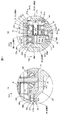
図4(a)及び(b)に示すように、軸受機構Aは、デフケース30の軸線方向に沿って互いに並列する玉軸受34,66(玉軸受34は図4(a)に、また玉軸受66は図4(b)にそれぞれ示す)を有し、出力機構53Aの軸線(軸線O1)上に配置されている。
As shown in FIGS. 4A and 4B, the bearing mechanism A includes
一方の玉軸受34は、その内外周部で互いに並列する内外2つの軌道輪340,341(内輪340,外輪341)、及び内輪340と外輪341との間で転動する転動体342を有し、内フランジ20bの減速伝達機構5側で切り欠き20cの切り欠き面(第1のハウジングエレメント20の内周面)とデフケース30の軸線方向一方側端部の外周面との間に介在して配置されている。そして、一方の玉軸受34は、デフケース30の反モータ側端部(モータ側端部と反対側の端部)を第1のハウジングエレメント20の内周面に回転可能に支持する。
One
内輪340は、一方側(電動モータ4側)端面340aをデフケース30の段差面30dに当接させてデフケース30の外周面に例えばしまりばめによって取り付けられている。
The
外輪341は、一方側端面341aを第1のハウジングエレメント20の内フランジ20bに、また他方側端面341bを止め輪73に当接させ、第1のハウジングエレメント20の内周面に例えばすきまばめによって取り付けられている。止め輪73は、第1のハウジングエレメント20にその内周面(切り欠き20cの切り欠き面)に突出させて取り付けられている。外輪341には、取付ボルト71(図2に示す)で第1のハウジングエレメント20を自転力付与部材52(第2のハウジングエレメント21)に取り付ける(締め付ける)ことにより、内フランジ20bから電動モータ4側にアキシアル荷重P=P1が予圧として付与されている。
The
転動体342は、内輪340と外輪341との間に介在して配置され、かつ保持器(図示せず)によって転動可能に保持されている。
The rolling
同様に、他方の玉軸受66は、その内外周部で互いに並列する内外2つの軌道輪660,661(内輪660,外輪661)、及び内輪660と外輪661との間で転動する転動体662を有し、減速伝達機構5のリヤディファレンシャル3側でフランジ30cの外周面と自転力付与部材52(第1の嵌合部52a)の内周面との間に介在して配置されている。そして、他方の玉軸受66は、デフケース30のモータ側端部(フランジ30c)を第1のハウジングエレメント20の内周面に回転可能に支持する。
Similarly, the
内輪660は、一方側(リヤディファレンシャル3側)端面660aをフランジ30cの凸部302cに当接させてフランジ30cの外周面に例えばとまりばめによって取り付けられている。内輪660には、複数の出力部材53をフランジ30cのピン取付孔301cに取り付けることにより、フランジ30cの凸部302cから電動モータ4側にアキシアル荷重P=P2が予圧として付与されている。
The
外輪661は、一方側(電動モータ4側)端面661aを自転力付与部材52のリヤディファレンシャル側端面52d(スペーサ68)に当接させ、第1の嵌合部52aの内周面にすきまばめによって取り付けられている。スペーサ68は、フランジ30cの外周囲で外輪661の一方側端面661aと自転力付与部材52のリヤディファレンシャル側端面52dとの間に介在して配置されている。
The
転動体662は、内輪660と外輪661との間に介在して配置され、かつ保持器(図示せず)によって転動可能に保持されている。
The rolling
このように構成されたモータ回転力伝達装置1においては、モータ軸42の回転に伴い入力部材50,51に発生する遠心力F=F1,F2に基づいてデフケース30にその回転を阻害するような荷重が作用すると、この荷重の作用方向にデフケース30が移動する。この場合、デフケース30の移動力が反モータ側(自転力付与部材52側と反対側)端部から玉軸受34を介して第1のハウジングエレメント20に作用し、第1のハウジングエレメント20が弾性変形する。一方、デフケース30の移動力がモータ側(自転力付与部材52側)端部から玉軸受66を介して自転力付与部材52に作用するが、自転力付与部材52が弾性変形することがない。仮に、自転力付与部材52が弾性変形しても、その変形量は第1のハウジングエレメント20の変形量に比べて小さい。これは、第1のハウジングエレメント20の材料の剛性が自転力付与部材52の材料の剛性よりも小さいため、上記遠心力F=F1,F2に基づく荷重を受けたデフケース30の反モータ側端部が玉軸受34を介して支持される第1のハウジングエレメント20はデフケース30が玉軸受66を介して支持される自転力付与部材52よりも弾性変形し易いことによる。これにより、自転力付与部材52を剛体としてその内周面に玉軸受66を介してデフケース30のモータ側端部が支持され、デフケース30と自転力付与部材52との間の芯ずれの発生を抑制することができる。
In the motor rotational force transmission device 1 configured as described above, the
(モータ回転力伝達装置1の動作)
次に、本実施の形態に示すモータ回転力伝達装置の動作につき、図1〜図3を用いて説明する。
(Operation of the motor rotational force transmission device 1)
Next, the operation of the motor torque transmission device shown in the present embodiment will be described with reference to FIGS.
図2において、モータ回転力伝達装置1の電動モータ4に電力を供給して電動モータ4を駆動すると、この電動モータ4のモータ回転力がモータ軸42を介して減速伝達機構5に付与され、減速伝達機構5が作動する。
In FIG. 2, when electric power is supplied to the electric motor 4 of the motor rotational force transmission device 1 to drive the electric motor 4, the motor rotational force of the electric motor 4 is applied to the deceleration transmission mechanism 5 via the
このため、減速伝達機構5において、入力部材50,51が例えば図3に示す矢印m1方向に偏心量δをもって円運動を行う。 Therefore, the speed reduction transmission mechanism 5 performs circular motion with a eccentricity δ is the input member 50, 51 in the arrow m 1 direction shown in FIG. 3, for example.
これに伴い、入力部材50が外歯50cを自転力付与部材52の内歯52cに噛合させながら軸線O2の回り(図3に示す矢印n1方向)に、また入力部材51が外歯51cを自転力付与部材52の内歯52cに噛合させながら軸線O´2の回り(図3に示す矢印l1方向)にそれぞれ自転する。この場合、入力部材50,51の自転によって図2に示すようにピン挿通孔50bの内周面が針状ころ軸受55のレース550に、またピン挿通孔51bの内周面が針状ころ軸受57のレース570にそれぞれ当接する。
Accordingly, the input member 50 is the axis O 2 while meshing with the
このため、出力部材53には入力部材50,51の公転運動が伝達されず、入力部材50,51の自転運動のみが伝達され、この自転運動による自転力が出力部材53からデフケース30にその回転力として出力される。
For this reason, the revolution movement of the input members 50 and 51 is not transmitted to the
これにより、リヤディファレンシャル3が作動し、電動モータ4のモータ回転力に基づく駆動力が図1におけるリヤアクスルシャフト106に配分され、左右の後輪105に伝達される。
As a result, the rear differential 3 is operated, and the driving force based on the motor rotational force of the electric motor 4 is distributed to the
なお、上記実施の形態においては、入力部材50,51を矢印m1方向に円運動させてモータ回転力伝達装置1を作動させる場合について説明したが、入力部材50,51を矢印m2方向に円運動させてもモータ回転力伝達装置1を上記実施の形態と同様に作動させることができる。この場合、入力部材50の自転運動は矢印n2方向に、また入力部材51の自転運動は矢印l2方向にそれぞれ行われる。 In the above embodiment has described the case where the input member 50, 51 by circular motion of the arrow m 1 direction to actuate the motor torque transmission device 1, the input member 50, 51 in the arrow m 2 Direction Even if it makes a circular motion, the motor rotational force transmission device 1 can be operated in the same manner as in the above embodiment. In this case, the rotation of the input member 50 is performed in the direction of the arrow n 2 , and the rotation of the input member 51 is performed in the direction of the arrow l 2 .
[実施の形態の効果]
以上説明した実施の形態によれば、次に示す効果が得られる。
[Effect of the embodiment]
According to the embodiment described above, the following effects can be obtained.
(1)デフケース30において、モータ側端部が玉軸受66を介して自転力付与部材52の内周面に、また反モータ側端部が玉軸受34を介して第1のハウジングエレメント20の内周面にそれそれ支持されているため、デフケース30と自転力付与部材52との軸心性が改善され、すなわちデフケース30と自転力付与部材52との間の芯ずれの発生を抑制することができ、入力部材50,51と自転力付与部材52との良好な噛み合いを得ることができる。
(1) In the
(2)自転力付与部材52がハウジング2の一部を構成する円筒部材によって形成されているため、自転力付与部材52をハウジング2内に収容する場合と比べて自転力付与部材52の外径を大きい寸法に設定することができ、自転力付与部材52の機械的強度を高めることができる。また、自転力付与部材52がハウジング2の一部を構成することは、装置全体の径方向寸法を短縮して小型化を図ることができる。
(2) Since the rotation force imparting member 52 is formed by a cylindrical member that constitutes a part of the
(3)自転力付与部材52の第1の嵌合部52aを凸部23の外周面に、また第2の嵌合部52bを凸部27の外周面にそれぞれ嵌合させて芯合わせを行うことができ、自転力付与部材52の製造加工を簡単に行うことができる。
(3) Centering is performed by fitting the first
以上、本発明の減速機構及びこれを備えたモータ回転力伝達装置を上記実施の形態に基づいて説明したが、本発明は上記実施の形態に限定されるものではなく、その要旨を逸脱しない範囲で種々の態様において実施することが可能であり、例えば次に示すような変形も可能である。 As mentioned above, although the deceleration mechanism of this invention and the motor rotational force transmission apparatus provided with this were demonstrated based on the said embodiment, this invention is not limited to the said embodiment, The range which does not deviate from the summary The present invention can be implemented in various modes, and for example, the following modifications are possible.
(1)上記実施の形態では、軸線O2から軸線O1までの距離と軸線O´2から軸線O1までの距離とを等しく、かつ軸線O2と軸線O´2との軸線O1回りの距離を等しくするように一方の偏心部42aと他方の偏心部42bとがモータ軸42の外周囲に配置されているとともに、軸線O1回りに互いに等間隔(180°)をもって離間する部位で一対の入力部材50,51が配置されている場合について説明したが、本発明はこれに限定されず、入力部材の個数は適宜変更することができる。
(1) In the above embodiment, equal to the distance from the distance and the axis O'2 from the axis O 2 to the axis O 1 to the axis O 1, and the axis O 1 around the axis O 2 and the axis O'2 with one to equal the distance of the
すなわち、入力部材がn(n≧3)個の場合には、電動モータ(モータ軸)の軸線に直交する仮想面において、第1の偏心部の軸線,第2の偏心部の軸線,…,第nの偏心部の軸線がモータ軸の軸線回りの一方向に順次配置されているものとすると、各偏心部の軸線からモータ軸の軸線までの距離を等しく、かつ第1の偏心部,第2の偏心部,…,第nの偏心部のうち互いに隣り合う2つの偏心部の軸線とモータ軸の軸線とを結ぶ線分でつくる挟角を360°/nとするように各偏心部がモータ軸の外周囲に配置されるとともに、軸線O1回りに360°/nの間隔をもって離間する部位でn個の入力部材が配置される。 That is, when there are n (n ≧ 3) input members, in the virtual plane orthogonal to the axis of the electric motor (motor shaft), the axis of the first eccentric part, the axis of the second eccentric part,. Assuming that the axis of the nth eccentric part is sequentially arranged in one direction around the axis of the motor shaft, the distance from the axis of each eccentric part to the axis of the motor shaft is equal, and the first eccentric part, Each of the eccentric portions is formed so that the included angle formed by a line segment connecting the axes of the two eccentric portions adjacent to each other among the two eccentric portions,..., The n-th eccentric portion and the axis of the motor shaft is 360 ° / n. The n input members are disposed at the outer periphery of the motor shaft and at a part spaced about 360 ° / n around the axis O 1 .
例えば、入力部材が3個の場合には、モータ軸の軸線に直交する仮想面において、第1の偏心部の軸線,第2の偏心部の軸線,第3の偏心部の軸線がモータ軸の軸線回りの一方向に順次配置されているものとすると、各偏心部の軸線からモータ軸の軸線までの距離を等しく、かつ第1の偏心部,第2の偏心部,第3の偏心部のうち互いに隣り合う2つの偏心部の軸線とモータ軸の軸線とを結ぶ線分でつくる挟角を120°とするように各偏心部がモータ軸の外周囲に配置されるとともに、その軸線回りに120°の間隔をもって離間する部位で3個の入力部材が配置される。 For example, when there are three input members, the axis of the first eccentric part, the axis of the second eccentric part, and the axis of the third eccentric part are on the motor axis on a virtual plane orthogonal to the axis of the motor shaft. If it is sequentially arranged in one direction around the axis, the distance from the axis of each eccentric part to the axis of the motor shaft is equal, and the first eccentric part, the second eccentric part, and the third eccentric part Each eccentric part is arranged on the outer periphery of the motor shaft so that the included angle formed by the line connecting the axis line of two eccentric parts adjacent to each other and the axis line of the motor shaft is 120 °. Three input members are arranged at portions separated by an interval of 120 °.
(2)上記実施の形態では、駆動源としてエンジン102及び電動モータ4を併用した四輪駆動車101に適用する場合について説明したが、本発明はこれに限定されず、電動モータのみを駆動源とした四輪駆動車又は二輪駆動車である電気自動車にも適用することができる。また、本発明は、エンジン,電動モータによる第1の駆動軸と電動モータによる第2の駆動軸とを有する四輪駆動車にも上記実施の形態と同様に適用可能である。
(2) In the above embodiment, the case where the present invention is applied to the four-
(3)上記実施の形態では、デフケース30の反モータ側端部の外周面と第1のハウジングエレメント20の内周面との間に深溝玉軸受である玉軸受34を、またデフケース30のモータ側端部の外周面と自転力付与部材52の内周面との間に深溝玉軸受である玉軸受66を用いる場合について説明したが、本発明はこれに限定されず、深溝玉軸受に換えて深溝玉軸受以外の玉軸受やころ軸受を用いてもよい。このような玉軸受やころ軸受は、例えばアンギュラ玉軸受,針状ころ軸受,棒状ころ軸受,円筒ころ軸受,円すいころ軸受,自動調心ころ軸受などが挙げられる。
(3) In the above embodiment, the
(4)上記実施の形態では、玉軸受34の内輪340がデフケース30の外周面にしまりばめで、また玉軸受66の内輪66がデフケース30(フランジ30c)の外周面にとまりばめでそれぞれ取り付けられている場合について説明したが、本発明はこれに限定されず、いずれの内輪,外輪もこれらが取り付けられる周面に対してしまりばめであっても、すきまばめであっても、あるいはとまりばめであってもよい。
(4) In the above embodiment, the
(5)上記実施の形態では、玉軸受66が自転力付与部材52の内周面に外輪661の外周面全体を対向させてデフケース30のモータ側端部を支持する場合について説明したが、本発明はこれに限定されず、図5に示すように玉軸受66が自転力付与部材52(第1の嵌合部52a)の内周面に外周面一部(第1のハウジングエレメント20の凸部23の外周面)を対向させてデフケース30のモータ側端部を支持してもよい。また、転がり軸受(玉軸受66)がハウジング(第1のハウジングエレメント20)及び自転力付与部材の両内周面に外輪の外周面を対向(当接)させて出力対象(デフケース30)を支持してもよい。すなわち要するに、本発明は、反モータ側の転がり軸受(一方の転がり軸受)及びモータ側の転がり軸受(他方の転がり軸受)のうち他方の転がり軸受が少なくとも外周面一部を自転力付与部材の内周面に対向させて出力対象を支持してもよい。
(5) In the above embodiment, the case where the
1…モータ回転力伝達装置、2…ハウジング、20…第1のハウジングエレメント、20a…シャフト挿通孔、20b…内フランジ、20c…切り欠き、21…第2のハウジングエレメント、21a…内フランジ、22…第3のハウジングエレメント、22a…シャフト挿通孔、22b…円筒部、22c…段差面、23…凸部、25…円環部材、27…凸部、3…リヤディファレンシャル、30…デフケース、30a…収容空間、30b…シャフト挿通孔、30c…フランジ、301c…ピン取付孔、302c…凸部、30d…段差面、30e…凹孔、300e…段差面、31…ピニオンギヤシャフト、32…ピニオンギヤ、33…サイドギヤ、34…玉軸受、340…内輪、340a…一方側端面、341…外輪、341a…一方側端面、341b…他方側端面、342…転動体、35…玉軸受、350…内輪、351…外輪、4…電動モータ、40…ステータ、41…ロータ、42…モータ軸、42a,42b…偏心部、42c…段差面、42d,42e,42g…段差面、43…取付ボルト、44…玉軸受、45…スリーブ、46…玉軸受、460…内輪、461…外輪、47…レゾルバ、470…ステータ、471…ロータ、5…減速伝達機構、50,51…入力部材、50a,51a…中心孔、50b,51b…ピン挿通孔、50c,51c…外歯、52…自転力付与部材、52a…第1の嵌合部、52b…第2の嵌合部、52c…内歯、52d…段差面、52e…ボルト挿通孔、53A…出力機構、53…出力部材、53a…ねじ部、53b…頭部、54…玉軸受、540,541…軌道輪(内輪540,外輪541)、55…針状ころ軸受、550…レース、56…玉軸受、560,561…軌道輪(内輪560,外輪561)、57…針状ころ軸受、570レース、58…スペーサ、66…玉軸受、660…内輪、660a…一方側端面、661…外輪、661a…一方側端面、662…転動体、68…スペーサ、71,72…取付ボルト、73…止め輪、101…四輪駆動車、102…エンジン、103…トランスアクスル、104…前輪、105…後輪、106…リヤアクスルシャフト、107…フロントアクスルシャフト、A…軸受機構、F…遠心力、L,O1,O2,O´2,O3,O4,O5…軸線、P…アキシアル荷重、δ…偏心量
DESCRIPTION OF SYMBOLS 1 ... Motor rotational force transmission apparatus, 2 ... Housing, 20 ... 1st housing element, 20a ... Shaft penetration hole, 20b ... Inner flange, 20c ... Notch, 21 ... 2nd housing element, 21a ... Inner flange, 22 3rd housing element, 22a ... Shaft insertion hole, 22b ... Cylindrical part, 22c ... Stepped surface, 23 ... Convex part, 25 ... Ring member, 27 ... Convex part, 3 ... Rear differential, 30 ... Differential case, 30a ... Housing space, 30b ... shaft insertion hole, 30c ... flange, 301c ... pin mounting hole, 302c ... convex portion, 30d ... step surface, 30e ... concave hole, 300e ... step surface, 31 ... pinion gear shaft, 32 ... pinion gear, 33 ... Side gear, 34 ... ball bearing, 340 ... inner ring, 340a ... one end face, 341 ... outer ring, 341a ... one end face, 41b ... the other side end face, 342 ... rolling element, 35 ... ball bearing, 350 ... inner ring, 351 ... outer ring, 4 ... electric motor, 40 ... stator, 41 ... rotor, 42 ... motor shaft, 42a, 42b ... eccentric part, 42c ... Step surface, 42d, 42e, 42g ... Step surface, 43 ... Mounting bolt, 44 ... Ball bearing, 45 ... Sleeve, 46 ... Ball bearing, 460 ... Inner ring, 461 ... Outer ring, 47 ... Resolver, 470 ... Stator, 471 ... Rotor, 5 ... Deceleration transmission mechanism, 50, 51 ... Input member, 50a, 51a ... Center hole, 50b, 51b ... Pin insertion hole, 50c, 51c ... External teeth, 52 ... Rotating force applying member, 52a ... First fitting 52b ... inner teeth, 52d ... step surface, 52e ... bolt insertion hole, 53A ... output mechanism, 53 ... output member, 53a ... screw part, 53b ... head, 54 ... Ball bearing, 5 DESCRIPTION OF SYMBOLS 0,541 ... Race ring (Inner ring 540, Outer ring 541), 55 ... Needle roller bearing, 550 ... Race, 56 ... Ball bearing, 560,561 ... Race ring (
Claims (4)
前記回転軸の前記偏心部の外周囲に回転可能に配置され、軸線回りに等間隔をもって並列する複数の貫通孔を有する外歯歯車からなる入力部材と、
前記入力部材に噛合し、前記外歯歯車の歯数よりも大きい歯数をもつ内歯歯車からなる自転力付与部材と、
前記自転力付与部材によって前記入力部材に付与された自転力を受けて出力対象にその回転力として出力し、前記複数の貫通孔をそれぞれ挿通する複数の出力部材を有する出力機構と、
前記出力機構の軸線上に配置され、前記出力対象の軸線方向に沿って互いに並列する一対の転がり軸受を有する軸受機構とを備え、
前記軸受機構は、前記出力対象を収容して前記自転力付与部材の材料の剛性よりも小さい剛性をもつ材料で形成されたハウジングの内周面に前記一対の転がり軸受のうち一方の転がり軸受が、また前記自転力付与部材の内周面に前記一対の転がり軸受のうち他方の転がり軸受が少なくとも外周面一部を対向させてそれぞれ前記出力対象を回転可能に支持する
減速機構。 A rotating shaft having an eccentric portion;
An input member comprising an external gear having a plurality of through-holes arranged rotatably around the eccentric portion of the rotating shaft and arranged in parallel at equal intervals around the axis;
A rotation force applying member that is engaged with the input member and includes an internal gear having a number of teeth larger than the number of teeth of the external gear;
An output mechanism having a plurality of output members that receive the rotation force applied to the input member by the rotation force applying member and output the rotation force to an output target, and respectively insert the plurality of through holes,
A bearing mechanism having a pair of rolling bearings arranged on the axis of the output mechanism and parallel to each other along the axial direction of the output target;
In the bearing mechanism, one of the pair of rolling bearings is provided on an inner peripheral surface of a housing that accommodates the output target and is formed of a material having rigidity smaller than that of the material of the rotation force applying member. Further, a speed reduction mechanism in which the other rolling bearing of the pair of rolling bearings faces at least a part of the outer circumferential surface and rotatably supports the output object, respectively, on an inner circumferential surface of the rotation force applying member.
前記電動モータの前記モータ回転力を減速して駆動力を出力する減速機構とを備えたモータ回転力伝達装置において、
前記減速機構は、請求項1乃至3のいずれか1項に記載の減速機構である
モータ回転力伝達装置。 An electric motor for generating motor rotational force;
A motor rotational force transmission device comprising a speed reduction mechanism that decelerates the motor rotational force of the electric motor and outputs a driving force;
The said deceleration mechanism is a deceleration mechanism of any one of Claims 1 thru | or 3. A motor rotational force transmission apparatus.
Priority Applications (4)
| Application Number | Priority Date | Filing Date | Title |
|---|---|---|---|
| JP2012155818A JP5910378B2 (en) | 2012-07-11 | 2012-07-11 | Deceleration mechanism and motor rotational force transmission device having the same |
| US13/933,449 US9033840B2 (en) | 2012-07-11 | 2013-07-02 | Speed reduction mechanism and motor torque transmission apparatus including the same |
| EP13175238.8A EP2685129B1 (en) | 2012-07-11 | 2013-07-05 | Speed reduction mechanism and motor torque transmission apparatus including the same |
| CN201310286626.9A CN103542042B (en) | 2012-07-11 | 2013-07-09 | Speed reduction mechanism and motor torque transmission apparatus including the same |
Applications Claiming Priority (1)
| Application Number | Priority Date | Filing Date | Title |
|---|---|---|---|
| JP2012155818A JP5910378B2 (en) | 2012-07-11 | 2012-07-11 | Deceleration mechanism and motor rotational force transmission device having the same |
Publications (2)
| Publication Number | Publication Date |
|---|---|
| JP2014016018A true JP2014016018A (en) | 2014-01-30 |
| JP5910378B2 JP5910378B2 (en) | 2016-04-27 |
Family
ID=48793889
Family Applications (1)
| Application Number | Title | Priority Date | Filing Date |
|---|---|---|---|
| JP2012155818A Expired - Fee Related JP5910378B2 (en) | 2012-07-11 | 2012-07-11 | Deceleration mechanism and motor rotational force transmission device having the same |
Country Status (4)
| Country | Link |
|---|---|
| US (1) | US9033840B2 (en) |
| EP (1) | EP2685129B1 (en) |
| JP (1) | JP5910378B2 (en) |
| CN (1) | CN103542042B (en) |
Families Citing this family (19)
| Publication number | Priority date | Publication date | Assignee | Title |
|---|---|---|---|---|
| WO2015104980A1 (en) * | 2014-01-08 | 2015-07-16 | Ntn株式会社 | In-wheel motor drive device |
| JP6326252B2 (en) * | 2014-03-13 | 2018-05-16 | ナブテスコ株式会社 | Reduction gear bearing preload mechanism |
| KR101746599B1 (en) * | 2015-06-08 | 2017-06-14 | 주식회사 세진아이지비 | Planetary gear system |
| KR101805576B1 (en) * | 2016-09-01 | 2017-12-07 | 주식회사 세진아이지비 | Planetary reduction gear device for ultra high reduction gear ratio |
| JP2019044936A (en) * | 2017-09-07 | 2019-03-22 | 日本電産株式会社 | transmission |
| JP6933099B2 (en) * | 2017-11-16 | 2021-09-08 | 株式会社ジェイテクト | Intermittent device |
| US10563729B2 (en) * | 2018-01-08 | 2020-02-18 | Schaeffler Technologies AG & Co. KG | Hyper-cycloidal differential |
| US10378613B1 (en) * | 2018-02-07 | 2019-08-13 | Schaeffler Technologies AG & Co. KG | Electric powertrain with cycloidal mechanism |
| US11820217B2 (en) * | 2018-02-19 | 2023-11-21 | Allison Transmission, Inc. | Axle assembly for frame rail vehicles |
| WO2019161390A1 (en) | 2018-02-19 | 2019-08-22 | Axletech International Ip Holdings, Llc | Axle assembly for frame rail vehicles |
| DE102019206063A1 (en) * | 2019-04-29 | 2020-10-29 | Audi Ag | Electric machine |
| JP7321894B2 (en) * | 2019-11-11 | 2023-08-07 | 住友重機械工業株式会社 | drive |
| JP2021193303A (en) * | 2020-06-08 | 2021-12-23 | 日本電産トーソク株式会社 | Electric actuator |
| JP7540919B2 (en) * | 2020-08-31 | 2024-08-27 | ナブテスコ株式会社 | Reducer, drive unit, and steering assist device |
| JP7840113B2 (en) * | 2020-08-31 | 2026-04-03 | ナブテスコ株式会社 | Reducer, drive unit, and steering assist device |
| CN115257329A (en) * | 2022-09-02 | 2022-11-01 | 重庆拓思动力科技有限公司 | Battery pack compact electric driving force unit and operation machine |
| CN116247874B (en) * | 2023-05-06 | 2023-08-11 | 哈尔滨艾拓普科技有限公司 | Cycloid differential driving module |
| FR3157498B1 (en) * | 2023-12-22 | 2026-03-13 | Ampere Sas | Arrangement for a geared motor including an element stiffening the rotor shaft of such a geared motor. |
| DE102024117936A1 (en) * | 2024-06-25 | 2026-01-08 | Schaeffler Technologies AG & Co. KG | Actuating device for actuating a friction clutch and differential for motor vehicles |
Citations (5)
| Publication number | Priority date | Publication date | Assignee | Title |
|---|---|---|---|---|
| JPS631838A (en) * | 1986-06-18 | 1988-01-06 | Amagasaki Kosakusho:Kk | Speed converter |
| JPH0480950U (en) * | 1990-11-27 | 1992-07-14 | ||
| JP2000329200A (en) * | 1999-03-16 | 2000-11-28 | Sumitomo Heavy Ind Ltd | Driving device and transmission gear with swinging inner gearing planetary gear structure |
| JP2001205377A (en) * | 2000-01-20 | 2001-07-31 | Sumitomo Heavy Ind Ltd | Method for manufacturing rotary roller body, rotary roller body obtained by the method and inrevolvable planetary gear structure with internal rotary roller body |
| JP2009052630A (en) * | 2007-08-24 | 2009-03-12 | Ntn Corp | In-wheel motor drive unit |
Family Cites Families (11)
| Publication number | Priority date | Publication date | Assignee | Title |
|---|---|---|---|---|
| GB1559276A (en) | 1975-11-04 | 1980-01-16 | Newage Engs Co | Motor in-wheel units |
| KR100301120B1 (en) * | 2000-04-27 | 2001-09-22 | 박용수 | Reducer having an internal planetary gear |
| JP4004256B2 (en) | 2001-09-13 | 2007-11-07 | ナブテスコ株式会社 | Eccentric rocking speed reducer |
| US7296644B2 (en) * | 2003-07-09 | 2007-11-20 | Tochigi Fuji Sangyo Kabushiki Kaisha | Reduction-drive device |
| EP1743796A3 (en) * | 2005-07-13 | 2007-03-28 | Kanzaki Kokyukoki MFG. Co., Ltd. | Wheel motor device |
| CN1895922A (en) * | 2005-07-13 | 2007-01-17 | 株式会社神崎高级工机制作所 | Wheel motor device |
| JP2007218407A (en) | 2006-02-20 | 2007-08-30 | Ntn Corp | Vehicle driving unit |
| US8480531B2 (en) * | 2007-02-02 | 2013-07-09 | Arvinmeritor Technology, Llc | Differential assembly with inverted bearing |
| JPWO2010038380A1 (en) | 2008-10-03 | 2012-02-23 | ナブテスコ株式会社 | Pitch drive device for windmill |
| US9074677B2 (en) * | 2011-03-14 | 2015-07-07 | Arvinmeritor Technology, Llc | Carrier assembly with threaded adjustment member |
| EP2602509B1 (en) | 2011-12-05 | 2014-04-16 | JTEKT Corporation | Speed reduction mechanism, and motor torque transmission device including the same |
-
2012
- 2012-07-11 JP JP2012155818A patent/JP5910378B2/en not_active Expired - Fee Related
-
2013
- 2013-07-02 US US13/933,449 patent/US9033840B2/en not_active Expired - Fee Related
- 2013-07-05 EP EP13175238.8A patent/EP2685129B1/en not_active Not-in-force
- 2013-07-09 CN CN201310286626.9A patent/CN103542042B/en not_active Expired - Fee Related
Patent Citations (5)
| Publication number | Priority date | Publication date | Assignee | Title |
|---|---|---|---|---|
| JPS631838A (en) * | 1986-06-18 | 1988-01-06 | Amagasaki Kosakusho:Kk | Speed converter |
| JPH0480950U (en) * | 1990-11-27 | 1992-07-14 | ||
| JP2000329200A (en) * | 1999-03-16 | 2000-11-28 | Sumitomo Heavy Ind Ltd | Driving device and transmission gear with swinging inner gearing planetary gear structure |
| JP2001205377A (en) * | 2000-01-20 | 2001-07-31 | Sumitomo Heavy Ind Ltd | Method for manufacturing rotary roller body, rotary roller body obtained by the method and inrevolvable planetary gear structure with internal rotary roller body |
| JP2009052630A (en) * | 2007-08-24 | 2009-03-12 | Ntn Corp | In-wheel motor drive unit |
Also Published As
| Publication number | Publication date |
|---|---|
| CN103542042B (en) | 2017-05-10 |
| US9033840B2 (en) | 2015-05-19 |
| US20140018202A1 (en) | 2014-01-16 |
| EP2685129A1 (en) | 2014-01-15 |
| EP2685129B1 (en) | 2015-08-19 |
| JP5910378B2 (en) | 2016-04-27 |
| CN103542042A (en) | 2014-01-29 |
Similar Documents
| Publication | Publication Date | Title |
|---|---|---|
| JP5910378B2 (en) | Deceleration mechanism and motor rotational force transmission device having the same | |
| US8734283B2 (en) | Speed reduction mechanism, and motor torque transmission device including the same | |
| JP6152680B2 (en) | Deceleration mechanism and motor rotational force transmission device having the same | |
| JP5817247B2 (en) | Motor rotational force transmission device | |
| JP5811335B2 (en) | Bearing device, reduction mechanism provided with the same, and motor torque transmission device | |
| US8721484B2 (en) | Speed reduction mechanism, and motor torque transmission device including the same | |
| JP2013029195A (en) | Motor driving force transmission device | |
| JP2013007443A (en) | Speed reduction mechanism and motor rotation force transmission device equipped with the same | |
| JP2013117284A (en) | Speed reduction mechanism, and motor torque transmission device including the same | |
| JP2014005890A (en) | Deceleration mechanism and motor torque transmission device including the same | |
| JP6089514B2 (en) | Reducer, motor rotational force transmission device including the same, and four-wheel drive vehicle | |
| JP6003557B2 (en) | Deceleration mechanism and motor rotational force transmission device having the same | |
| JP6028386B2 (en) | Deceleration mechanism and motor rotational force transmission device having the same | |
| JP2013142447A (en) | Speed reduction mechanism, and motor torque transmission device including the same | |
| JP2014001813A (en) | Speed reduction mechanism and motor rotational force transmission device including the same | |
| JP2014016019A (en) | Speed reduction mechanism and motor rotational force transmission device including the same | |
| JP5849783B2 (en) | Deceleration mechanism and motor rotational force transmission device having the same | |
| JP2014025511A (en) | Speed reduction mechanism and motor rotational force transmission device including the same | |
| JP2014005892A (en) | Deceleration mechanism and motor torque transmission device including the same | |
| JP2014005891A (en) | Deceleration mechanism and motor torque transmission device including the same | |
| JP2014016017A (en) | Speed reduction mechanism and motor rotational force transmission device including the same | |
| JP2014001814A (en) | Speed reduction mechanism and motor rotational force transmission device including the same |
Legal Events
| Date | Code | Title | Description |
|---|---|---|---|
| A621 | Written request for application examination |
Free format text: JAPANESE INTERMEDIATE CODE: A621 Effective date: 20150623 |
|
| A977 | Report on retrieval |
Free format text: JAPANESE INTERMEDIATE CODE: A971007 Effective date: 20151028 |
|
| A131 | Notification of reasons for refusal |
Free format text: JAPANESE INTERMEDIATE CODE: A131 Effective date: 20151104 |
|
| A521 | Request for written amendment filed |
Free format text: JAPANESE INTERMEDIATE CODE: A523 Effective date: 20151216 |
|
| TRDD | Decision of grant or rejection written | ||
| A01 | Written decision to grant a patent or to grant a registration (utility model) |
Free format text: JAPANESE INTERMEDIATE CODE: A01 Effective date: 20160301 |
|
| A61 | First payment of annual fees (during grant procedure) |
Free format text: JAPANESE INTERMEDIATE CODE: A61 Effective date: 20160314 |
|
| R150 | Certificate of patent or registration of utility model |
Ref document number: 5910378 Country of ref document: JP Free format text: JAPANESE INTERMEDIATE CODE: R150 |
|
| LAPS | Cancellation because of no payment of annual fees |