JP2013520370A - Bounce cap - Google Patents
Bounce cap Download PDFInfo
- Publication number
- JP2013520370A JP2013520370A JP2012553839A JP2012553839A JP2013520370A JP 2013520370 A JP2013520370 A JP 2013520370A JP 2012553839 A JP2012553839 A JP 2012553839A JP 2012553839 A JP2012553839 A JP 2012553839A JP 2013520370 A JP2013520370 A JP 2013520370A
- Authority
- JP
- Japan
- Prior art keywords
- sealing device
- pivot member
- pivot
- main body
- retracted position
- Prior art date
- Legal status (The legal status is an assumption and is not a legal conclusion. Google has not performed a legal analysis and makes no representation as to the accuracy of the status listed.)
- Pending
Links
- 238000007789 sealing Methods 0.000 claims abstract description 74
- 230000006835 compression Effects 0.000 claims description 8
- 238000007906 compression Methods 0.000 claims description 8
- 230000000994 depressogenic effect Effects 0.000 claims description 2
- 239000002828 fuel tank Substances 0.000 abstract description 8
- 239000010687 lubricating oil Substances 0.000 abstract description 3
- 238000002485 combustion reaction Methods 0.000 description 4
- 239000000314 lubricant Substances 0.000 description 2
- 230000000452 restraining effect Effects 0.000 description 2
- 244000025254 Cannabis sativa Species 0.000 description 1
- 230000008878 coupling Effects 0.000 description 1
- 238000010168 coupling process Methods 0.000 description 1
- 238000005859 coupling reaction Methods 0.000 description 1
- 239000012530 fluid Substances 0.000 description 1
- 239000000446 fuel Substances 0.000 description 1
- 239000003502 gasoline Substances 0.000 description 1
- 239000000463 material Substances 0.000 description 1
Images


Classifications
-
- B—PERFORMING OPERATIONS; TRANSPORTING
- B60—VEHICLES IN GENERAL
- B60K—ARRANGEMENT OR MOUNTING OF PROPULSION UNITS OR OF TRANSMISSIONS IN VEHICLES; ARRANGEMENT OR MOUNTING OF PLURAL DIVERSE PRIME-MOVERS IN VEHICLES; AUXILIARY DRIVES FOR VEHICLES; INSTRUMENTATION OR DASHBOARDS FOR VEHICLES; ARRANGEMENTS IN CONNECTION WITH COOLING, AIR INTAKE, GAS EXHAUST OR FUEL SUPPLY OF PROPULSION UNITS IN VEHICLES
- B60K15/00—Arrangement in connection with fuel supply of combustion engines or other fuel consuming energy converters, e.g. fuel cells; Mounting or construction of fuel tanks
- B60K15/03—Fuel tanks
- B60K15/04—Tank inlets
- B60K15/0406—Filler caps for fuel tanks
- B60K2015/0432—Filler caps for fuel tanks having a specific connection between the cap and the vehicle or tank opening
- B60K2015/0445—Filler caps for fuel tanks having a specific connection between the cap and the vehicle or tank opening using hinges
Landscapes
- Engineering & Computer Science (AREA)
- Transportation (AREA)
- Sustainable Development (AREA)
- Sustainable Energy (AREA)
- Chemical & Material Sciences (AREA)
- Combustion & Propulsion (AREA)
- Life Sciences & Earth Sciences (AREA)
- Mechanical Engineering (AREA)
- Closures For Containers (AREA)
- Closing And Opening Devices For Wings, And Checks For Wings (AREA)
- Cooling, Air Intake And Gas Exhaust, And Fuel Tank Arrangements In Propulsion Units (AREA)
- Lock And Its Accessories (AREA)
- Portable Power Tools In General (AREA)
Abstract
本発明は、燃料タンク又は潤滑油タンクのようなタンクの、補給開口部を封止するための封止装置2に関する。封止装置は、補給開口部との係合のための本体部20を有する。更に、封止装置2は、把持部3を備える枢動部材6を有する。把持部3は、格納ポジションと突出ポジションとの間で切り替えられてもよい。突出ポジションにおいて、把持部3は、使用者に便利な把持部を形成するため、本体部20の外方に延出する。保持部材13、14、17は、突出ポジションにおいて枢動部材6を保持するために提供さてもよい。保持部材13、14、17は、枢動部材6及び本体部20に固定されてもよい。更に、封止装置2は、枢動部材6を格納ポジションへと移動させるために構成された付勢部材11を有する。
【選択図】図5The present invention relates to a sealing device 2 for sealing a replenishment opening of a tank such as a fuel tank or a lubricating oil tank. The sealing device has a main body 20 for engagement with the replenishment opening. Furthermore, the sealing device 2 has a pivoting member 6 with a gripping part 3. The grip part 3 may be switched between a storage position and a protruding position. In the protruding position, the grip portion 3 extends outward from the main body portion 20 to form a grip portion convenient for the user. Holding members 13, 14, 17 may be provided for holding the pivot member 6 in the extended position. The holding members 13, 14, and 17 may be fixed to the pivot member 6 and the main body portion 20. In addition, the sealing device 2 has a biasing member 11 configured to move the pivoting member 6 to the retracted position.
[Selection] Figure 5
Description
本発明は、燃料タンク又は潤滑油タンクのようなタンクのための封止装置に関する。更に詳細には、携帯可能なコンパクト工具のタンクのための封止装置に関する。 The present invention relates to a sealing device for a tank such as a fuel tank or a lubricating oil tank. More particularly, it relates to a sealing device for a portable compact tool tank.
内燃機関は、制限するものではないが、チェーンソー、ヘッジトリマー、グラストリマー、ブロワー、草刈機等の様々なコンパクト工具で幅広く使用されている。機関駆動のコンパクト工具は、補給開口部を備える燃料タンク又は潤滑油タンクのようなタンクを有する。タンクのねじ加工された給油口のための従来の封止装置は、対応する補給開口部のねじ部と係合可能なねじキャップを有する。ねじ加工されたキャップは、補給開口部にキャップを締め付けることによって、外気に対して補給開口部を堅く封止する。 Internal combustion engines are widely used in various compact tools such as, but not limited to, chainsaws, hedge trimmers, grass trimmers, blowers, mowers and the like. Engine-driven compact tools have a tank, such as a fuel tank or a lubricant tank with a replenishment opening. A conventional sealing device for a threaded tank fill has a screw cap that is engageable with a thread in the corresponding refill opening. The screwed cap tightly seals the supply opening against the outside air by tightening the cap on the supply opening.
従来の多くの封止装置は、使用者にとって好ましくない把持部を設けている。更に、キャップが封止ポジションにあるときに外方に突出するキャップ部は、使用者が把持するために使用される。加えて、開放可能な把持部を備えるキャップも、コンパクト工具で使用されている。開放可能な把持部は、キャップを解放するとき又は締め付けるとき、使用者が、より把持し易いように開放される。 Many conventional sealing devices are provided with a grip portion that is undesirable for the user. Further, the cap portion protruding outward when the cap is in the sealing position is used for the user to hold. In addition, caps with openable grips are also used in compact tools. The releasable gripping part is opened to make it easier for the user to grip when releasing or tightening the cap.
これらのキャップは従来のキャップよりは良いが、開放可能な把持部が意図せずに開放されてしまうという問題に悩まされる。開放可能な把持部が意図せず開放されることは、キャップの破損又はキャップの意図しない解放を生じさせ得る。従って、限定するものではないが、コンパクト工具の燃料タンク又は潤滑油タンクのようなタンクのための封止装置のニーズがある。更に、キャップを解放するとき又は締め付けるときに、使用者が、より把持し易い封止装置のニーズがある。 These caps are better than conventional caps, but suffer from the problem that the openable gripping part is unintentionally opened. Unintentional opening of the releasable grip can cause breakage of the cap or unintentional release of the cap. Accordingly, there is a need for a sealing device for a tank such as, but not limited to, a compact tool fuel tank or lubricant tank. Further, there is a need for a sealing device that is easier for the user to grip when releasing or tightening the cap.
上述の点を考慮し、上で説明した問題を解決又は少なくとも低減することが目的となる。特に、コンパクト電動工具の燃料タンク又は潤滑油タンクのようなタンクの補給開口部を封止するための手段を提供することが目的となる。封止手段は、使用者が握り易いように開放されてもよい。 In view of the above, it is an object to solve or at least reduce the problems described above. In particular, it is an object to provide means for sealing a replenishment opening of a tank such as a fuel tank or a lubricating oil tank of a compact electric tool. The sealing means may be opened so that the user can easily grasp it.
この目的は、請求項1に記載のコンパクト電動工具における、タンクの補給開口部を封止するための封止装置によって実現することができる。封止装置は、本体部と枢動部材とを有する。本体部は、補給開口部と係合するために構成されてもよい。本体部は、長手方向軸線も画成する。枢動部材は、格納ポジションと突出ポジションとの間の移動のため枢動軸線周りで枢動可能とされてもよく、枢動可能に本体部と接続されてもよい。枢動部材は、突出ポジションにおいて把持可能となるために本体部の外方に延出する把持部を有する。これは、封止装置を緩めるとき又は締め付けるときに使用者を補助する。封止装置は、枢動部材が突出ポジションにおいて保持部材によって拘束可能であり、保持部材の第1部分が枢動部材に固定されており、且つ、保持部材の第2部分が本体部に固定されていることを特徴とする。加えて封止装置は、更に枢動部材を格納ポジションへと付勢するために構成された付勢部材を具備することも特徴とする。 This object can be realized by the sealing device for sealing the replenishment opening of the tank in the compact electric tool according to claim 1. The sealing device has a main body portion and a pivot member. The body portion may be configured to engage with the refill opening. The body portion also defines a longitudinal axis. The pivot member may be pivotable about a pivot axis for movement between the retracted position and the protruding position, and may be pivotably connected to the body portion. The pivot member has a grip portion extending outward from the main body portion so that the pivot member can be gripped at the protruding position. This assists the user when loosening or tightening the sealing device. In the sealing device, the pivot member can be restrained by the holding member at the protruding position, the first portion of the holding member is fixed to the pivot member, and the second portion of the holding member is fixed to the main body portion. It is characterized by. In addition, the sealing device further includes a biasing member configured to bias the pivot member to the retracted position.
こうした封止装置は、突出している把持部によって、封止装置を締め付けること及び緩めることが容易となる。タンクが開放されるとき又は封止されるとき、彼又は彼女が、例えばグローブを装着している場合であっても、把持部が突出ポジションにおいて拘束され得るため、使用者にとって使用が容易となる。同時に、枢動部材が拘束可能な突出ポジションから解放されるとき、付勢部材は、格納ポジションへと枢動部材を付勢する。それによって、封止装置は、枢動部材が突出ポジションにないとき、平らな外部表面を自動的に提供することができる。更に、電動工具を操作するとき、例えば枝等のような物が枢動部材に引っかかった場合に枝が枢動部材を移動させるとき、枢動部材は再び格納ポジションへと付勢される。そうではなく、枢動部材が、格納ポジションから離れた位置に留まる場合、封止装置が損傷する危険性、又は、意図せずに封止装置が緩まる危険性がある。本体は、補給開口部の対応するねじ部と係合するためのねじ部を有してもよい。更に、本体部及び補給開口部は、別の実施形態において、差し込みカップリング、スナップ手段等のようなねじ以外の他の係合手段を有してもよい。 Such a sealing device can be easily tightened and loosened by the protruding gripping portion. When the tank is opened or sealed, it is easy for the user to use because the gripping part can be restrained in the protruding position, even if he or she is wearing a glove, for example . At the same time, when the pivot member is released from the constrained protruding position, the biasing member biases the pivot member to the retracted position. Thereby, the sealing device can automatically provide a flat outer surface when the pivot member is not in the extended position. Furthermore, when operating the power tool, for example when an object such as a branch is caught on the pivot member, the branch moves the pivot member, and the pivot member is again biased to the retracted position. Rather, if the pivot member remains away from the retracted position, there is a risk of damage to the sealing device or unintentional loosening of the sealing device. The body may have a threaded portion for engaging a corresponding threaded portion of the refill opening. Furthermore, the main body and the replenishment opening may have other engaging means other than screws, such as plug couplings, snap means, etc., in another embodiment.
請求項2によれば、保持部材が、枢動部材に取付けられた第1固定部材と、本体部に取付けられた第2固定部材と、を具備する実施形態が提供されている。第1固定部材及び第2固定部材は、枢動部材が突出ポジションにあるときに互いに係合するために取付けられている。 According to claim 2, there is provided an embodiment in which the holding member includes a first fixing member attached to the pivot member and a second fixing member attached to the main body. The first fixing member and the second fixing member are attached to engage each other when the pivot member is in the protruding position.
固定部材は、使用者が枢動部材を突出ポジションへと移動させるときに互いに係合するように構成されてもよい。そのようにして、枢動部材を拘束可能な突出ポジションへと移動させるためにはいくらかのトルクが必要となるため、枢動部材に引っかかり得る枝は、枢動部材を拘束可能な突出ポジションへと移動させることはできない。更に、固定部材は、使用者が封止装置を緩めるとき又は締め付けるときに突出ポジションにある枢動部材のために、強力保持機能を設けてもよい。固定部材を互いに解放するための必要トルク量は、枢動部材を格納ポジションへと付勢する付勢部材によって付与されるトルク量より大きい。 The securing members may be configured to engage each other when the user moves the pivot member to the projected position. In that way, some torque is required to move the pivot member to the restraining protruding position, so that a branch that can be caught on the pivot member is moved to the protruding position where the pivot member can be restrained. It cannot be moved. Furthermore, the fixing member may provide a strong holding function for the pivot member in the protruding position when the user loosens or tightens the sealing device. The amount of torque required to release the fixing members from each other is greater than the amount of torque provided by the biasing member that biases the pivot member to the retracted position.
更なる実施形態において、保持部材は弾性部材であってもよい。それによって、部材の弾性は、枢動部材を拘束可能な突出ポジションへ移動させるために必要な力で設定されてもよい。 In a further embodiment, the holding member may be an elastic member. Thereby, the elasticity of the member may be set with the force required to move the pivot member to a constrained protruding position.
請求項4による実施形態において、閾値ポジションは、格納ポジションと突出ポジションとの間の枢動部材、及び、閾値ポジションと突出ポジションとの間の枢動部材の位置のために構成されており、弾性部材は、枢動部材を突出ポジションへと付勢する。 In an embodiment according to claim 4, the threshold position is configured for a pivot member between the retracted position and the protruding position and a position of the pivot member between the threshold position and the protruding position, The member biases the pivot member to the protruding position.
枢動部材を突出ポジションへと付勢することによって、枢動部材を移動させる際、突出ポジションに容易に到達することができる。枢動部材は、使用者が枢動部材を閾値ポジションを通過させて移動させるまで、連続的に枢動部材を突出ポジションへと付勢する弾性部材によって、突出ポジションで保持される。 By biasing the pivot member to the protruding position, the protruding position can be easily reached when the pivot member is moved. The pivot member is held in the protruding position by an elastic member that continuously biases the pivot member to the protruding position until the user moves the pivot member past the threshold position.
別の実施形態において、弾性部材は、一方の端部において枢動部材に取付けられ、且つ、他方の端部において本体部に取付けられたばねであってもよい。更に別の実施形態において、弾性部材は、円錐圧縮ばねであってもよい。 In another embodiment, the elastic member may be a spring attached to the pivot member at one end and attached to the body at the other end. In yet another embodiment, the elastic member may be a conical compression spring.
弾性部材としてばねを設けることによって、枢動部材が閾値ポジションと突出ポジションとの間の位置にあるとき、ばねは、枢動部材において突出ポジションへの付勢機能を付与することができる。枢動部材が突出ポジションにあるとき、ばねは、ばねの力によって枢動部材を突出ポジションに保持してもよい。 By providing a spring as an elastic member, when the pivot member is in a position between the threshold position and the protruding position, the spring can provide a biasing function to the protruding position in the pivot member. When the pivot member is in the extended position, the spring may hold the pivot member in the extended position by the force of the spring.
請求項7による実施形態において、付勢部材は弾性部材と同一でもよく、且つ、閾値ポジションと格納ポジションとの間の枢動部材の位置のため、弾性部材は、枢動部材を格納ポジションへと付勢する。
In an embodiment according to
これは、弾性部材が枢動部材及び本体部に取付けられたばねであるときに設けられてもよい。枢動部材が閾値ポジションの一方にあるとき、ばねは、枢動部材を格納ポジションへと付勢する。枢動部材が閾値ポジションの他方にある場合、ばねは、枢動部材を突出ポジションへと付勢し、次いで枢動部材を、封止装置を緩めるとき又は締め付けるときに使用者のために把持を支援する突出ポジションに保持する。封止装置の構造は、同一の部材で枢動部材を格納ポジション及び突出ポジションの両方へ付勢すれば、簡潔且つ費用効率を高くすることができる。閾値ポジションの位置は、ばね及び枢動部材の設計によって設定されてもよい。更に枢動部材を突出ポジションへ又は突出ポジションから移動させるための必要トルクがばねの力によって設定されてもよい。 This may be provided when the elastic member is a spring attached to the pivot member and the body portion. When the pivot member is in one of the threshold positions, the spring biases the pivot member to the retracted position. When the pivot member is in the other of the threshold positions, the spring biases the pivot member to the protruding position and then grips the pivot member for the user when loosening or tightening the sealing device. Hold in the protruding position to support. The structure of the sealing device can be simple and cost effective if the pivot member is biased to both the retracted position and the protruding position with the same member. The position of the threshold position may be set by the design of the spring and pivot member. Further, the required torque for moving the pivot member to or from the protruding position may be set by the spring force.
請求項8によれば、枢動部材が少なくとも1つのピン周りで又は少なくとも1つのピンと共に枢動可能であってもよく、その、少なくとも1つのピンが本体部に固定されてもよい実施形態が提供されている。この場合において、付勢部材は、枢動部材を付勢し、格納ポジションに戻すため、その少なくとも1つのピンに周設されたねじりばねであってもよい。 According to claim 8, an embodiment in which the pivot member may be pivotable about or together with at least one pin, the at least one pin being fixed to the body part. Is provided. In this case, the biasing member may be a torsion spring provided around the at least one pin for biasing the pivot member and returning it to the retracted position.
保持部材又は弾性部材が、こうした付勢機能を設けていない場合、ねじりばねが、格納ポジションへと向かう枢動部材の付勢機能を設けてもよい。それによって、枢動部材は、意図せずに移動させられたときには常に格納ポジションに戻るように付勢されてもよい。枢動部材を格納ポジションへと戻すように付勢するためにねじりばねによって付与されたトルクは、枢動部材を突出ポジションから移動させるための必要トルクよりも小さい。 If the holding member or the elastic member does not provide such an urging function, the torsion spring may provide the urging function of the pivoting member toward the storage position. Thereby, the pivot member may be biased to return to the retracted position whenever it is moved unintentionally. The torque applied by the torsion spring to bias the pivot member back to the retracted position is less than the torque required to move the pivot member from the protruding position.
更なる実施形態において、枢動部材は、把持部に対して枢動軸線の反対側に配置されたカウンター部を有してもよい。枢動部材が格納ポジションから突出ポジションへと移動させられたときにカウンター部を受容するため、本体部内に凹部が設けられてもよい。 In a further embodiment, the pivoting member may have a counter part arranged on the opposite side of the pivot axis with respect to the gripping part. A recess may be provided in the body portion for receiving the counter portion when the pivot member is moved from the retracted position to the protruding position.
請求項10による実施形態において、枢動部材を格納ポジションから移動させるのを補助するため、カウンター部が押し下げられるように構成されてもよい。更に、請求項11によれば、カウンター部の一部は、枢動部材の格納ポジション内の本体部の包囲する表面を越えて所定距離だけ突出してもよい。
In an embodiment according to
それによって、枢動部材は、使用者が、例えばグローブを装着している場合であっても格納ポジションから回転させるのが容易となる。彼又は彼女は、格納ポジションから移動させるために枢動部材の把持部の端部を把持することができないものと想定される。把持部を格納ポジションから持ち上げるためには、カウンター部を押せるだけで十分である。 Thereby, it becomes easy for the user to rotate the pivot member from the retracted position even when the user is wearing a glove, for example. It is envisaged that he or she will not be able to grip the end of the gripping portion of the pivot member in order to move it from the retracted position. In order to lift the gripping part from the storage position, it is sufficient to push the counter part.
請求項12による実施形態において、把持部は、枢動軸線から距離Aだけ延出してもよく、且つ、カウンター部は、枢動軸線から少なくとも0.25A、好適には少なくとも0.35Aの距離だけ延出してもよく、少なくとも0.45Aの距離だけ延出すると更に好ましい。
In an embodiment according to
こうしたカウンター部の延出部によって、カウンター部は、使用者が枢動部材の把持部を持ち上げるためにカウンター部を押す必要がある場合において、小さすぎることはない。カウンター部の延出部が小さすぎる場合、カウンター部の表面領域は、使用者が押すのには小さすぎてしまい、把持部を持ち上げるためカウンター部を押すのに要求される力も、大きすぎてしまう。 With such an extension of the counter part, the counter part is not too small when the user needs to push the counter part in order to lift the gripping part of the pivot member. If the extension part of the counter part is too small, the surface area of the counter part will be too small for the user to push and the force required to push the counter part to lift the grip part will be too great. .
更なる実施形態において、枢動部材は、枢動部材の格納ポジションのために本体部の内部に突出する固定部を有してもよい。次いで弾性部材は、枢動部材の固定部に固定される。更に弾性部材が枢動可能に固定部に固定されてもよい。 In a further embodiment, the pivot member may have a fixed portion that projects into the interior of the body portion for the retracted position of the pivot member. Next, the elastic member is fixed to the fixed portion of the pivot member. Further, the elastic member may be fixed to the fixing portion so as to be pivotable.
更に、格納ポジションからの枢動部材の移動及び突出ポジションにおける把持部の把持を容易にするため、少なくとも枢動部材の一部は、1つの実施形態において、本体部の反対側に面した枢動部材の表面に表面構造が設けられてもよい。表面構造は、溝、凹部、リブ等であってもよい。 Further, to facilitate movement of the pivot member from the retracted position and gripping of the grip portion in the extended position, at least a portion of the pivot member, in one embodiment, pivots facing the opposite side of the body portion. A surface structure may be provided on the surface of the member. The surface structure may be a groove, a recess, a rib or the like.
本発明は、以下に、添付の図面を参照して更に詳細に説明される。 The invention will now be described in more detail with reference to the accompanying drawings.
発明の好適な実施形態が示された添付の図面を参照しながら、本発明は、以下に、より詳細に説明される。しかしながら、ここで本発明は、多くの様々な形式で具体化されてもよく、むしろ、これらの実施形態は、この開示を徹底するため、及び、完全なものとするため、且つ、当業者に本発明の範囲を詳細に説明するために示されている。本図面において、同様な番号は、同様な説明を参照する。 The present invention will be described in more detail below with reference to the accompanying drawings, in which preferred embodiments of the invention are shown. However, the invention herein may be embodied in many different forms, but rather, these embodiments are intended to be thorough and complete, and to those skilled in the art. The scope of the present invention is shown in detail. In the drawings, like numbers refer to like descriptions.
図1は、本発明に係る例示的実施形態による、例えば、チェーンソーの操作部1の斜視図を示す。例示的実施形態がチェーンソーと共に使用されることが示されているが、本発明が、任意の適した携帯可能なコンパクト電動工具の類型に組み込まれることができ、チェーンソーのみの使用に制限されず、且つ、様々な類型の実施形態に組み込まれ得ることを理解すべきである。以下で「コンパクト電動工具1」と呼ぶ操作部1は、造園又は林業での用途で使用されてもよい。コンパクト電動工具1は、内燃機関(図示せず)によって駆動されてもよい。更に、内燃機関は、ガソリンエンジンであっても、ディーゼルエンジンであってもよい。本発明に係る実施形態において、タンクは、内燃機関の燃料タンクであってもよい。燃料タンクは、封止装置2の対応するねじ部と係合するためのねじ部を備える補給開口部(図示せず)を有してもよい。封止装置2を補給開口部に締め付けることによって、外気に対してシールされる方法で補給開口部を封止するために封止装置2が使用されてもよい。 FIG. 1 shows a perspective view of an operating part 1 of a chain saw, for example, according to an exemplary embodiment according to the invention. Although an exemplary embodiment has been shown to be used with a chainsaw, the present invention can be incorporated into any suitable portable compact power tool type and is not limited to the use of only a chainsaw, And it should be understood that it can be incorporated into various types of embodiments. The operation unit 1, which will be referred to as “compact power tool 1” below, may be used for landscaping or forestry. The compact power tool 1 may be driven by an internal combustion engine (not shown). Furthermore, the internal combustion engine may be a gasoline engine or a diesel engine. In the embodiment according to the present invention, the tank may be a fuel tank of an internal combustion engine. The fuel tank may have a replenishment opening (not shown) with a thread for engaging a corresponding thread on the sealing device 2. The sealing device 2 may be used to seal the replenishment opening in a manner that is sealed against the outside air by clamping the sealing device 2 to the replenishment opening.
図2は、封止装置2の斜視図を示す。封止装置2は、補給開口部の対応するねじ部と係合するためのねじ部4を備える本体部20を有する。補給開口部は、封止装置2の本体部20をコンパクト電動工具1の燃料タンクの補給開口部へ締め付けることによって封止されてもよい。封止装置2は、実質的に平らな上面を有する。更に封止装置2は、封止装置2が完全に補給開口部に係合されたときに流体密封シールを画成するスカート部5を有する。図2について説明すれば、枢動部材6は、枢動軸線XX’を通るピン7周りに枢動可能に画成されている。
FIG. 2 shows a perspective view of the sealing device 2. The sealing device 2 has a
枢動部材6は、格納ポジションと、突出ポジションとの間で切り替えるために枢動可能に本体部20に接続されている。
The
更に、枢動部材6は、コンパクト電動工具1の使用者に握り易さを提供するための把持部3を有する。把持部3の形状は半円であってもよい。しかしながら、把持部3が任意の適した形状を有し得ることは、当業者にとって明白である。更に、枢動部材6は、把持部3に対して、枢動軸線XX’の反対側に位置するカウンター部8を有する。カウンター部8は、本体部20の反対側に面した枢動部材6の表面の溝、リブ又は凹部のような表面構造を有する。図2について説明すると、枢動部材6の格納ポジションにおいて、カウンター部8は、本体部20の包囲する表面を、本体部20の長手方向軸線Yに沿って長手方向へと越え、距離を隔てて突出する。これは、カウンター部8を押して把持部3を開くのを容易にする。把持部3は、(図4に示すように)枢動軸線XX’から、距離Aだけ延出し、且つ、カウンター部8は、枢動軸線XX’から、距離Bだけ延出する。距離Bは、枢動軸線XX’から少なくとも0.25×Aの距離である。例として、距離Aが2cmであれば、距離Bは、少なくとも0.5cmである。他の実施形態において、距離Bは、枢動軸線XX’から、少なくとも0.35×A又は0.45×Aの距離であってもよい。その場合、距離Aが2cmであれば、距離Bは、少なくとも0.7cm又は0.9cmである。好適には、把持部3の延出距離Aとは無関係に、カウンター部は、枢動軸線XX’から少なくとも0.5cm延出する。
Furthermore, the
凹部10は、図2に示すように、把持部3の外周に形成される。把持部3は、指先を凹部10に挿入することによって開かれてもよい。枢動部材6が格納ポジションから移動させるのを補助するため、カウンター部8は、更に封止装置2内へ押し下げられてもよい。例えば使用者がグローブを装着している場合、彼又は彼女は、把持部3を格納ポジションから移動させるため、且つ、把持部3を、凹部10で握ることができるようにするためにカウンター部8を押圧することができる。
The recessed
更に、封止装置2は、枢動部材6を突出ポジションで保持する弾性部材を有してもよい。弾性部材は、枢動部材6及び本体部に固定されてもよい。本発明に係る様々な実施形態において、弾性部材はばねであってもよく、好適には、圧縮ばね又は円錐圧縮ばねである。弾性部材は図6を用いて説明される。
Furthermore, the sealing device 2 may have an elastic member that holds the
図3は、突出ポジションにある把持部3を備えた封止装置2の斜視図を示す。封止装置2は、図3に示すようにピン7を包囲する付勢部材11を有する。付勢部材11の第1端部は、把持部3に固定され、付勢部材11の第2端部12は、本体部20に固定されている。付勢部材11は、枢動部材6が突出ポジションにある限り、枢動部材6を格納ポジションへと付勢する。付勢部材11は、枢動部材6を付勢して格納ポジションに戻すためにピン7に周設されたねじりばねであってもよい。更に、付勢部材11は、圧縮ばね又は円錐圧縮ばねであってもよい。本発明に係る実施形態において、弾性部材及び付勢部材11は、同様な部材であってもよい。
FIG. 3 shows a perspective view of the sealing device 2 with the gripping part 3 in the protruding position. The sealing device 2 has a biasing
図4は、格納ポジションにある把持部3を備えた封止装置2の断面図を示す。封止装置2は、枢動部材固定ユニット13及び本体部固定ユニット14を有する。枢動部材固定ユニット13は、本体部20に接続された一又はそれ以上の固定部材を有する枢動部材6及び本体部固定ユニット14に接続された一又はそれ以上の固定部材を有する。特に、枢動部材固定ユニット13の固定部材は、突出ポジションにおいて枢動部材6を保持するために本体部固定ユニット14の対応する部材と係合する。突出ポジションにおいて、枢動部材6の把持部3は、把持可能となるために、本体部20の外方に延出する。使用者は、把持部を用いて封止装置2を容易に緩めたり、締め付けたりすることができる。
FIG. 4 shows a sectional view of the sealing device 2 with the gripping part 3 in the retracted position. The sealing device 2 includes a pivot
図4について説明すると、カウンター部8は、枢動部材6の格納ポジションにおいて、本体部20の包囲する表面を、本体部20の長手方向軸線Yに沿って長手方向へと越え、距離を隔てて突出する。カウンター部8が本体部20を越えて突出しているため、それによって、カウンター部8を押して、把持部3を持ち上げるのが容易となる。封止装置2の本体部20は、カウンター部8を受容するための凹部15を有する。特に、枢動部材6のカウンター部8は、枢動部材6が格納ポジションから突出ポジションへと移動するときに、凹部15内へと移動する。
Referring to FIG. 4, the counter unit 8 extends in the longitudinal direction along the longitudinal axis Y of the
封止装置2は、シールリング16も有する。シールリング16は、弾性ゴム材料で作られてもよく、それは、封止装置がコンパクト電動工具のタンクの開口部に取付けられるときに、例えば燃料の漏れを防ぐ。
The sealing device 2 also has a
図5は、突出ポジションにある把持部3を備えた封止装置2の断面図を示す。突出ポジションにおいて、枢動部材固定ユニット13の固定部材及び本体部固定ユニット14の固定部材は、スナップ固定手段を形成する。枢動部材固定ユニット13の固定部材は、フレキシブル部材であってもよく、且つ、本体部固定ユニット14の固定部材は、フレキシブル部材を保持するための座部であってもよい。本体部固定ユニット14の固定部材は、フレキシブル部材であってもよく、枢動部材固定ユニット13の固定部材は、フレキシブル部材を保持するための座部であってもよい。固定手段を解放するための必要トルクは、付勢部材11によって付勢されるトルクより大きく、こうして枢動部材6が突出ポジションで保持される。それによって、枢動部材6は、突出ポジションから使用者によって解放されなければならず、自ずから解放されたりはしない。拘束ポジションで係合する固定手段のための必要トルクも、電動工具の操作中に把持手段に引っ掛かり得る枝等によって通常生じ得るトルクより大きい。
FIG. 5 shows a cross-sectional view of the sealing device 2 with the gripping part 3 in the protruding position. In the protruding position, the fixing member of the pivot
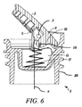
図6は、閾値ポジションと格納ポジションとの間に配置された枢動部材6を備える封止装置2の断面図を示す。閾値ポジションは、格納ポジションと、枢動部材6の突出ポジションと、の間に構成されている。弾性部材17は、枢動部材6を、突出ポジションで保持することができる。枢動部材6が、閾値ポジションと突出ポジションとの間にあるとき、弾性部材17は、枢動部材6を、突出ポジションへと付勢させる。こうして、枢動部材6の閾値ポジションから突出ポジションへの小さな回転でさえ、枢動部材6を突出ポジションへと付勢させる。同様に、枢動部材6が閾値ポジションを通過して、格納ポジションへと移動させられるとき、弾性部材17は、枢動部材6を格納ポジションへと付勢する。それによって、付勢部材11の機能は、弾性部材17に組み込まれる。
FIG. 6 shows a cross-sectional view of the sealing device 2 comprising a
弾性部材17は、ばねであってもよく、好適には、圧縮ばね又は円錐圧縮ばねである。ばね17の第1部分は、本体部20の凹部15の底部に固定される。ばね17の第2部は、図6に示すように枢動可能に枢動部材6の固定部18に固定される。固定部18は、枢動部材6の格納ポジションのため、本体部20の内部に突出する。ばね17と固定部18との間の接続点に、ばね17が枢動可能に固定部18に固定されている固定軸線19がある。固定軸線19は、枢動部材6がその周りで回転する可枢動ピンと平行である。枢動部材6が、閾値ポジションと格納ポジションとの間の位置にあるとき、ばね17は、固定部18とカウンター部8とを、可枢動ピン7の上方へ、同じ側に、図中の右へと押し、こうして枢動部材6が格納ポジションへと押される。
The
その周りを枢動部材が回転する可枢動ピン7と固定軸線19とが、ばね17の長手方向中心と、同一線上にあるとき、枢動部材6は、閾値ポジションにある。閾値ポジションと突出ポジションとの間の枢動部材の位置において、ばねは、固定部18及び固定軸線19を一方へ、図中の可枢動ピン7の左に上方へと押す。カウンター部8は、それから可枢動ピン7の右側の反対側の、下方に、本体部20の凹部15内へ押圧される。これは、固定部18によって画成されたカウンター部8と固定軸線19との間の距離によるものである。それによって、把持部3は、本体部20から突出しており、ばね17によってその位置で保持されている。枢動部材を、閾値ポジションを経て突出ポジションへと移動させるための必要トルクは、ばね17のばねの力によって設定される。更に、格納ポジションと突出ポジションとの間の閾値ポジションの位置が、ばね17と固定部18との構成によって設定されてもよい。
When the
図及び明細書において、本発明の好適な実施形態及び例が開示され、特定の用語が採用されてきたが、それらは、一般的且つ記述的意味のみで使用されており、限定するためではなく、本発明の範囲は以下の特許請求の範囲において説明される。 In the drawings and specification, preferred embodiments and examples of the invention have been disclosed and specific terms have been employed, but are used in a general and descriptive sense only and not for purposes of limitation. The scope of the invention is set forth in the following claims.
Claims (14)
長手方向軸線(Y)を画成し、前記補給開口部と係合するための本体部(20)と、
格納ポジション及び突出ポジション間の移動のため枢動軸線(XX’)周りで枢動可能で、且つ、枢動可能に前記本体部(20)に接続され、把持部(3)を有する枢動部材(6)と、を具備し、前記突出ポジションにおいて、前記把持部(3)が、把持可能となるために前記本体部(20)の外方に延出し、それによって封止装置(2)を緩めること及び締め付けることを補助する封止装置(2)において、
前記枢動部材(6)が、保持部材(13、14、17)によって前記突出ポジションで拘束可能であり、
該保持部材の第1部分(13)が、前記枢動部材(6)に固定され、且つ、該保持部材の第2部分(14)が、前記本体部(20)に固定されており、
更に封止装置(2)が、前記枢動部材(6)を前記格納ポジションへと付勢するために構成された付勢部材(11、17)を具備していることを特徴とする封止装置(2)。 A sealing device (2) for sealing a replenishment opening of a tank in (1) a compact electric tool, the sealing device comprising:
A body (20) for defining a longitudinal axis (Y) and engaging with the replenishment opening;
A pivot member pivotable about a pivot axis (XX ′) for movement between the retracted position and the projecting position, and pivotally connected to the body portion (20) and having a grip portion (3) (6), and in the projecting position, the gripping part (3) extends outward from the main body part (20) so that the gripping part (3) can be gripped, thereby the sealing device (2). In the sealing device (2) to assist in loosening and tightening:
The pivot member (6) can be restrained in the protruding position by a holding member (13, 14, 17);
A first part (13) of the holding member is fixed to the pivot member (6), and a second part (14) of the holding member is fixed to the main body (20);
The sealing device (2) further comprises a biasing member (11, 17) configured to bias the pivot member (6) to the retracted position. Device (2).
前記本体部(20)が、前記格納ポジションから前記突出ポジションへと前記枢動部材(6)が移動するときに前記カウンター部(8)を受容するための凹部(15)を有している請求項1から請求項8のいずれか1つに記載の封止装置。 The pivot member (6) has a counter part (8) arranged on the opposite side of the pivot axis (XX ') with respect to the grip part (3);
The said main-body part (20) has a recessed part (15) for receiving the said counter part (8), when the said pivot member (6) moves from the said storage position to the said protrusion position. The sealing device according to any one of claims 1 to 8.
Applications Claiming Priority (1)
| Application Number | Priority Date | Filing Date | Title |
|---|---|---|---|
| PCT/SE2010/050207 WO2011105937A1 (en) | 2010-02-23 | 2010-02-23 | Flip up cap |
Related Child Applications (1)
| Application Number | Title | Priority Date | Filing Date |
|---|---|---|---|
| JP2015146851A Division JP2015226980A (en) | 2015-07-24 | 2015-07-24 | Flip-up cap |
Publications (1)
| Publication Number | Publication Date |
|---|---|
| JP2013520370A true JP2013520370A (en) | 2013-06-06 |
Family
ID=44507083
Family Applications (1)
| Application Number | Title | Priority Date | Filing Date |
|---|---|---|---|
| JP2012553839A Pending JP2013520370A (en) | 2010-02-23 | 2010-02-23 | Bounce cap |
Country Status (7)
| Country | Link |
|---|---|
| US (2) | US9260008B2 (en) |
| EP (2) | EP2539171B1 (en) |
| JP (1) | JP2013520370A (en) |
| CN (1) | CN102770299B (en) |
| BR (1) | BR112012020352B1 (en) |
| RU (1) | RU2510711C1 (en) |
| WO (1) | WO2011105937A1 (en) |
Cited By (3)
| Publication number | Priority date | Publication date | Assignee | Title |
|---|---|---|---|---|
| JP2016117501A (en) * | 2014-12-19 | 2016-06-30 | 株式会社やまびこ | Tank cap |
| JP2017536907A (en) * | 2014-12-24 | 2017-12-14 | コーニンクレッカ フィリップス エヌ ヴェKoninklijke Philips N.V. | Anti-drip attachment for food processing equipment |
| JP2022540648A (en) * | 2019-07-11 | 2022-09-16 | マーティンリア インターナショナル ユーエス インク. | Composite spring for capless door |
Families Citing this family (12)
| Publication number | Priority date | Publication date | Assignee | Title |
|---|---|---|---|---|
| DE102013009087A1 (en) | 2013-05-29 | 2014-12-04 | GM Global Technology Operations, LLC (n.d. Ges. d. Staates Delaware) | Locking unit, tank unit and motor vehicle |
| JP6473431B2 (en) | 2016-04-01 | 2019-02-20 | 株式会社ニトリホールディングス | Storage case and hinge structure |
| JP6929748B2 (en) * | 2017-09-29 | 2021-09-01 | 株式会社マキタ | Tank cap |
| GB201717480D0 (en) | 2017-10-24 | 2017-12-06 | Nicoventures Holdings Ltd | Electronic aerosol provision device with seal |
| GB201717486D0 (en) | 2017-10-24 | 2017-12-06 | Nicoventures Holdings Ltd | Mechanism for hatch of electronic aerosol provision device |
| GB201717479D0 (en) | 2017-10-24 | 2017-12-06 | Nicoventures Holdings Ltd | Hatch section for an electronic aerosol provision device |
| GB201717484D0 (en) | 2017-10-24 | 2017-12-06 | Nicoventures Holdings Ltd | Electronic aerosol provision device |
| GB201717489D0 (en) | 2017-10-24 | 2017-12-06 | Nicoventures Holdings Ltd | Electronic aerosol provision device |
| RU2739630C2 (en) * | 2019-02-12 | 2020-12-28 | Федеральное государственное бюджетное образовательное учреждение высшего образования Балтийский государственный технический университет "ВОЕНМЕХ" им. Д.Ф. Устинова (БГТУ "ВОЕНМЕХ") | Closing mechanism |
| WO2020236046A1 (en) * | 2019-05-20 | 2020-11-26 | Husqvarna Ab | Power tool tank assembly,closure device, and power tool |
| DE202019104547U1 (en) * | 2019-08-19 | 2020-11-26 | Rpc Formatec Gmbh | Donor |
| CN114056440B (en) * | 2021-12-01 | 2025-06-03 | 长春捷翼汽车科技股份有限公司 | A dustproof device with self-locking and rebound functions and a charging device |
Family Cites Families (40)
| Publication number | Priority date | Publication date | Assignee | Title |
|---|---|---|---|---|
| US1689979A (en) * | 1928-02-14 | 1928-10-30 | Homer E Tate | Gas-tank cap |
| US1818608A (en) * | 1929-05-08 | 1931-08-11 | George C Chafkin | Safety gas tank cap |
| DE697929C (en) | 1938-09-11 | 1940-10-28 | E H Dr Phil H C Ernst Heinkel | Container screw connection, especially for aircraft |
| SE329355B (en) | 1969-02-25 | 1970-10-05 | L Ekman | |
| US3820680A (en) * | 1972-11-20 | 1974-06-28 | Stant Mfg Co | Torque-limiting device |
| DE7616881U1 (en) | 1976-05-26 | 1976-09-16 | Bayerische Motoren Werke Ag, 8000 Muenchen | FUEL TANK FOR SINGLE TRACK VEHICLES, IN PARTICULAR MOTORCYCLES |
| US4124151A (en) | 1976-11-22 | 1978-11-07 | Polytop Corporation | Toggle type dispensing closure |
| US4091959A (en) * | 1977-02-03 | 1978-05-30 | Banion John D O | Gas cap |
| JPS55131823U (en) | 1979-03-13 | 1980-09-18 | ||
| JPS591890Y2 (en) | 1981-04-23 | 1984-01-19 | バイエリツシエ モ−ト−レン ウエルケ アクチエンゲゼルシヤフト | Fuel tanks for single-track vehicles, especially motorcycles |
| US4402435A (en) | 1981-05-15 | 1983-09-06 | Libit Sidney M | Dispensing type cap closure |
| US4399928A (en) | 1982-04-14 | 1983-08-23 | Janler Corporation | Closure cap |
| JPS596524U (en) | 1982-07-06 | 1984-01-17 | 三菱自動車工業株式会社 | Cover structure of vehicle fuel filler port |
| JPS6041339U (en) | 1983-08-30 | 1985-03-23 | 株式会社 共立 | Tank cap for power working machines |
| DE3336149A1 (en) | 1983-10-05 | 1985-04-18 | Fa. Andreas Stihl, 7050 Waiblingen | SCREW CAP FOR FUEL TANK |
| DE8405440U1 (en) | 1984-02-22 | 1984-04-12 | Walter Alfmeier GmbH + Co Präzisions-Baugruppenelemente, 8830 Treuchtlingen | Closure device of a container |
| US5339487A (en) * | 1990-01-19 | 1994-08-23 | Rexair, Inc. | Filtering means for a liquid pan assembly for a liquid bath vacuum cleaner |
| DE4436543C2 (en) * | 1993-11-12 | 2002-07-11 | Stihl Maschf Andreas | Tensioning device for a chain saw of a motor chain saw running over a saw blade |
| US5480055A (en) * | 1994-05-06 | 1996-01-02 | Stant Manufacturing Inc. | Quick-on cap with removal delay mechanism |
| FR2743786B1 (en) | 1996-01-23 | 1999-04-16 | Stihl Maschf Andreas | PLUG FOR A FILLING OPENING OF A FUEL TANK |
| US6237797B1 (en) | 1999-10-29 | 2001-05-29 | John J. Hurford | Fuel cap extension |
| US6560879B2 (en) * | 2001-08-02 | 2003-05-13 | Wci Outdoor Products, Inc. | Chain saw adjuster |
| DE60202737T2 (en) * | 2001-11-26 | 2006-02-23 | Toyoda Gosei Co., Ltd. | cap assembly |
| JP2003341706A (en) | 2002-05-20 | 2003-12-03 | Kioritz Corp | Tank cap |
| JP4349785B2 (en) | 2002-10-11 | 2009-10-21 | 日本クラウンコルク株式会社 | Synthetic resin container lid with tamper evident characteristics |
| CA2484590A1 (en) | 2002-12-20 | 2004-07-15 | Sgg Patents Llc | Sport ball with self-contained inflation mechanism having pressure relief capability |
| US7467736B2 (en) | 2003-09-22 | 2008-12-23 | L'oreal | Closure and dispensing device |
| US6877233B1 (en) * | 2004-01-08 | 2005-04-12 | Electrolux Home Products, Inc. | Chain saw adjuster mechanism with locking teeth |
| EP1607294A1 (en) | 2004-06-18 | 2005-12-21 | Ford Global Technologies, LLC | Filler cap for under bonnet applications |
| US6968874B1 (en) * | 2004-10-07 | 2005-11-29 | Martinrea Industries, Inc. | Capless automotive fueling system |
| US7107689B2 (en) * | 2004-10-08 | 2006-09-19 | Husqvarna Outdoor Products Inc. | Bar knob with integrated lock |
| USD537024S1 (en) * | 2005-06-17 | 2007-02-20 | Kawasaki Jukogyo Kabushiki Kaisha | Fuel tank cap for a vehicle |
| DE102005047882B4 (en) | 2005-10-06 | 2017-04-27 | Andreas Stihl Ag & Co. Kg | Hand-held implement |
| US7588159B2 (en) * | 2005-10-21 | 2009-09-15 | Nissan Technical Center North America, Inc. | Fuel cap for vehicle |
| RU2312775C1 (en) | 2006-03-16 | 2007-12-20 | Общество с ограниченной ответственностью "Нижегородское производственное объединение "Волга" Всероссийского общества слепых" | Filler neck plug of automobile fuel tank (two versions) |
| US7739800B2 (en) * | 2006-10-24 | 2010-06-22 | Hurley Edward P | Combination blower, trimmer and edger for tending vegetation |
| WO2008108690A1 (en) | 2007-03-02 | 2008-09-12 | Husqvarna Aktiebolag | Filler cap |
| US8146770B2 (en) | 2007-06-19 | 2012-04-03 | Duncan Newman | Adjustable closure for a container |
| GB2450720A (en) | 2007-07-04 | 2009-01-07 | Black & Decker Inc | Power cutter with pleated filter |
| RU2363597C1 (en) | 2007-10-31 | 2009-08-10 | Институт физики им. Л.В. Киренского Сибирского отделения РАН | Vehicle fuel tank filler cover |
-
2010
- 2010-02-23 WO PCT/SE2010/050207 patent/WO2011105937A1/en not_active Ceased
- 2010-02-23 BR BR112012020352-5A patent/BR112012020352B1/en active IP Right Grant
- 2010-02-23 CN CN201080064584.9A patent/CN102770299B/en active Active
- 2010-02-23 JP JP2012553839A patent/JP2013520370A/en active Pending
- 2010-02-23 EP EP10846732.5A patent/EP2539171B1/en active Active
- 2010-02-23 US US13/580,504 patent/US9260008B2/en not_active Ceased
- 2010-02-23 EP EP17171723.4A patent/EP3243681B1/en active Active
- 2010-02-23 US US15/457,090 patent/USRE47046E1/en active Active
- 2010-02-23 RU RU2012140507/02A patent/RU2510711C1/en active
Cited By (4)
| Publication number | Priority date | Publication date | Assignee | Title |
|---|---|---|---|---|
| JP2016117501A (en) * | 2014-12-19 | 2016-06-30 | 株式会社やまびこ | Tank cap |
| JP2017536907A (en) * | 2014-12-24 | 2017-12-14 | コーニンクレッカ フィリップス エヌ ヴェKoninklijke Philips N.V. | Anti-drip attachment for food processing equipment |
| JP2022540648A (en) * | 2019-07-11 | 2022-09-16 | マーティンリア インターナショナル ユーエス インク. | Composite spring for capless door |
| JP7407905B2 (en) | 2019-07-11 | 2024-01-04 | マーティンリア インターナショナル ユーエス インク. | Composite spring for capless doors |
Also Published As
| Publication number | Publication date |
|---|---|
| US9260008B2 (en) | 2016-02-16 |
| US20120318797A1 (en) | 2012-12-20 |
| RU2012140507A (en) | 2014-03-27 |
| EP2539171A1 (en) | 2013-01-02 |
| BR112012020352B1 (en) | 2020-12-15 |
| CN102770299A (en) | 2012-11-07 |
| EP3243681B1 (en) | 2019-07-17 |
| RU2510711C1 (en) | 2014-04-10 |
| USRE47046E1 (en) | 2018-09-18 |
| CN102770299B (en) | 2016-08-03 |
| EP2539171B1 (en) | 2019-07-10 |
| EP3243681A1 (en) | 2017-11-15 |
| BR112012020352A2 (en) | 2016-05-03 |
| EP2539171A4 (en) | 2017-11-08 |
| WO2011105937A1 (en) | 2011-09-01 |
Similar Documents
| Publication | Publication Date | Title |
|---|---|---|
| JP2013520370A (en) | Bounce cap | |
| US6834769B2 (en) | Hinge cap | |
| JP5570761B2 (en) | Structure to prevent the protector fixture from falling off in garden tools | |
| JP5486214B2 (en) | Power tools | |
| CN104070232A (en) | Guide bar fastening device for chain saw | |
| CN201566932U (en) | Cover for fluid container | |
| JP2007519424A5 (en) | ||
| CA2629019C (en) | Handle latching mechanism | |
| US6109467A (en) | Closure cap for an operating fluid container | |
| JPH0914002A (en) | Hand lever device | |
| CN109573307B (en) | Box cover | |
| JP3209567U (en) | Sealing device | |
| JP2015226980A (en) | Flip-up cap | |
| US20130091973A1 (en) | Accelerator | |
| US6857413B2 (en) | Power working machine with internal combustion engine having spark plug | |
| US8308014B2 (en) | Fuel cap of internal combustion device | |
| CN102554839B (en) | Quick Action Wrench | |
| CN221930769U (en) | Garden tool | |
| WO2008108690A1 (en) | Filler cap | |
| CN222096399U (en) | Rotary handle and hand-held power tool with a rotary handle | |
| JP4988400B2 (en) | Tank cap | |
| TWI374218B (en) | ||
| CN102227330A (en) | Closure arrangement | |
| JP2505161Y2 (en) | Bucket with hose closure | |
| JP2508305Y2 (en) | Fuel equipment for power work equipment |
Legal Events
| Date | Code | Title | Description |
|---|---|---|---|
| A977 | Report on retrieval |
Free format text: JAPANESE INTERMEDIATE CODE: A971007 Effective date: 20131205 |
|
| A131 | Notification of reasons for refusal |
Free format text: JAPANESE INTERMEDIATE CODE: A131 Effective date: 20140128 |
|
| A601 | Written request for extension of time |
Free format text: JAPANESE INTERMEDIATE CODE: A601 Effective date: 20140425 |
|
| A602 | Written permission of extension of time |
Free format text: JAPANESE INTERMEDIATE CODE: A602 Effective date: 20140507 |
|
| A521 | Request for written amendment filed |
Free format text: JAPANESE INTERMEDIATE CODE: A523 Effective date: 20140718 |
|
| A02 | Decision of refusal |
Free format text: JAPANESE INTERMEDIATE CODE: A02 Effective date: 20150324 |