JP2013190569A - Imaging apparatus - Google Patents
Imaging apparatus Download PDFInfo
- Publication number
- JP2013190569A JP2013190569A JP2012056181A JP2012056181A JP2013190569A JP 2013190569 A JP2013190569 A JP 2013190569A JP 2012056181 A JP2012056181 A JP 2012056181A JP 2012056181 A JP2012056181 A JP 2012056181A JP 2013190569 A JP2013190569 A JP 2013190569A
- Authority
- JP
- Japan
- Prior art keywords
- focus
- lens
- focus adjustment
- subject
- target subject
- Prior art date
- Legal status (The legal status is an assumption and is not a legal conclusion. Google has not performed a legal analysis and makes no representation as to the accuracy of the status listed.)
- Pending
Links
Images



Landscapes
- Automatic Focus Adjustment (AREA)
- Studio Devices (AREA)
- Focusing (AREA)
Abstract
【課題】動画像を良好に撮影できる撮像装置を提供する。
【解決手段】光学系からの光束に基づいて、被写体を検出する被写体検出部170と、検出された被写体の中から対象被写体を選択する選択部170と、光学系の焦点状態を検出する焦点検出部163と、焦点検出結果に基づいて、焦点調節レンズ212を光軸方向に駆動させることで、光学系の焦点調節を行う焦点調節部170と、焦点調節レンズ212を対象被写体に合焦するレンズ位置まで駆動させる際の焦点調節レンズ212の駆動速度を、撮影者が入力可能な入力部150と、撮影者により入力された焦点調節レンズ212の駆動速度を取得する取得部170と、を備え、焦点調節部170は、対象被写体が選択された場合に、撮影者により設定された焦点調節レンズ212の駆動速度で、焦点調節レンズ212を、対象被写体に合焦するレンズ位置まで駆動させることを特徴とする撮像装置。
【選択図】 図1An imaging apparatus capable of satisfactorily capturing a moving image is provided.
A subject detection unit that detects a subject based on a light beam from an optical system, a selection unit that selects a subject from the detected subjects, and focus detection that detects a focus state of the optical system. A focus adjustment unit 170 that adjusts the focus of the optical system by driving the focus adjustment lens 212 in the optical axis direction based on the focus detection result, and a lens that focuses the focus adjustment lens 212 on the target subject. An input unit 150 that allows the photographer to input the driving speed of the focus adjustment lens 212 when driving to the position, and an acquisition unit 170 that acquires the driving speed of the focus adjustment lens 212 input by the photographer. When the target subject is selected, the focus adjustment unit 170 sets the focus adjustment lens 212 as the target subject at the driving speed of the focus adjustment lens 212 set by the photographer. Imaging apparatus characterized by driving to the lens position where the focus.
[Selection] Figure 1
Description
本発明は、撮像装置に関する。 The present invention relates to an imaging apparatus.
従来より、動画撮影が可能な撮像装置が知られている。このような撮像装置において、動画撮影中に顔などの被写体の検出を行い、検出した被写体にピントが合うように、光学系の焦点調節を行う技術が知られている(たとえば、特許文献1参照)。 2. Description of the Related Art Conventionally, imaging devices capable of moving image shooting are known. In such an imaging apparatus, a technique is known in which an object such as a face is detected during moving image shooting, and the focus of the optical system is adjusted so that the detected object is in focus (see, for example, Patent Document 1). ).
動画撮影時に、対象とする被写体にゆっくりとピントを合わせていくことで、映画的な演出効果を得る撮影方法が知られている。しかしながら、従来技術では、このような撮影方法で動画撮影を行う場合には、撮影者が焦点調節レンズをマニュアルで駆動させて、対象とする被写体にゆっくりとピントを合わせる必要があるため、動画像を良好に撮影することが困難な場合があった。 2. Description of the Related Art There is a known shooting method that obtains a cinematic effect by slowly focusing on a target subject during movie shooting. However, in the prior art, when taking a moving image with such a shooting method, the photographer needs to manually focus the target subject by manually driving the focus adjustment lens. It was sometimes difficult to shoot well.
本発明が解決しようとする課題は、動画像を良好に撮影できる撮像装置を提供することである。 The problem to be solved by the present invention is to provide an imaging apparatus capable of capturing a moving image satisfactorily.
本発明は、以下の解決手段によって上記課題を解決する。なお、以下においては、本発明の実施形態を示す図面に対応する符号を付して説明するが、この符号は本発明の理解を容易にするためだけのものであって発明を限定する趣旨ではない。 The present invention solves the above problems by the following means. In the following description, the reference numerals corresponding to the drawings showing the embodiments of the present invention are used for explanation, but these reference numerals are only for facilitating the understanding of the present invention and are not intended to limit the invention. Absent.
[1]本発明に係る撮像装置は、焦点調節レンズ(212)を有する光学系からの光束に基づいて、被写体を検出する被写体検出部(170)と、前記被写体検出部により検出された被写体の中から対象被写体を選択する選択部(170)と、前記光学系の焦点状態を検出する焦点検出部(163)と、前記焦点検出部による焦点検出結果に基づいて、前記焦点調節レンズを光軸方向に駆動させることで、前記光学系の焦点調節を行う焦点調節部(170)と、前記焦点調節レンズを前記対象被写体に合焦するレンズ位置まで駆動させる際の前記焦点調節レンズの駆動速度を、撮影者が入力可能な入力部(150,152)と、前記入力部を介して、撮影者により入力された前記焦点調節レンズの駆動速度を取得する取得部(170)と、を備え、前記焦点調節部は、前記対象被写体が選択された場合に、前記撮影者により設定された焦点調節レンズの駆動速度で、前記焦点調節レンズを、前記対象被写体に合焦するレンズ位置まで駆動させることを特徴とする。 [1] An imaging apparatus according to the present invention includes a subject detection unit (170) for detecting a subject based on a light beam from an optical system having a focus adjustment lens (212), and a subject detected by the subject detection unit. Based on the focus detection result by the selection part (170) which selects a target object from the inside, the focus detection part (163) which detects the focus state of the optical system, and the focus detection part, the focus adjustment lens is moved to the optical axis. By driving in the direction, the focus adjustment unit (170) that adjusts the focus of the optical system, and the drive speed of the focus adjustment lens when driving the focus adjustment lens to a lens position that focuses on the target subject. An input unit (150, 152) that can be input by the photographer, and an acquisition unit (170) that acquires the driving speed of the focusing lens input by the photographer via the input unit. When the target subject is selected, the focus adjustment unit drives the focus adjustment lens to a lens position that focuses on the target subject at a driving speed of the focus adjustment lens set by the photographer. It is characterized by that.
[2] 上記撮像装置に係る発明において、動画撮影モードを設定可能なモード設定部(150)をさらに備え、前記焦点調節部(170)は、前記動画撮影モードに設定されている場合において、前記対象被写体が選択された場合に、前記撮影者により設定された焦点調節レンズの駆動速度で、前記焦点調節レンズ(212)を、前記対象被写体に合焦するレンズ位置まで駆動させるように構成することができる。 [2] In the invention related to the imaging apparatus, the image pickup apparatus further includes a mode setting unit (150) capable of setting a moving image shooting mode, and the focus adjusting unit (170) is set to the moving image shooting mode. When the target subject is selected, the focus adjustment lens (212) is driven to the lens position that focuses on the target subject at the driving speed of the focus adjustment lens set by the photographer. Can do.
[3] 上記撮像装置に係る発明において、前記焦点検出部(163)は、前記光学系による像面のずれ量を検出することで、前記光学系の焦点検出を行う位相差検出方式の焦点検出が可能なように構成することができる。 [3] In the invention related to the imaging apparatus, the focus detection unit (163) detects a shift amount of the image plane by the optical system, thereby detecting a focus of the optical system by detecting a focus of the optical system. Can be configured.
[4] 上記撮像装置に係る発明において、前記焦点調節部(170)は、前記対象被写体が選択された場合に、前記焦点調節レンズ(212)を前記対象被写体に合焦するレンズ位置まで駆動させた後に、前記焦点調節レンズを、前記対象被写体よりも所定距離だけ至近側または無限遠側の位置まで駆動させるように構成することができる。 [4] In the invention related to the imaging apparatus, the focus adjustment unit (170) drives the focus adjustment lens (212) to a lens position for focusing on the target subject when the target subject is selected. After that, the focus adjustment lens can be configured to be driven to a position on the near side or the infinity side by a predetermined distance from the target subject.
[5] 上記撮像装置に係る発明において、前記入力部(150)は、前記焦点調節レンズ(212)の駆動を開始してから前記対象被写体に合焦するまでの時間を入力可能であり、前記焦点調節部(170)は、前記入力部を介して、撮影者により前記対象被写体に合焦するまでの時間が入力された場合には、前記対象被写体が選択された場合に、前記撮影者に入力された時間で前記対象被写体に合焦できる前記焦点調節レンズの駆動速度を算出し、算出した駆動速度で、前記焦点調節レンズを、前記対象被写体に合焦するレンズ位置まで駆動させるように構成することができる。 [5] In the invention related to the imaging apparatus, the input unit (150) can input a time from when the focus adjustment lens (212) is started to when the target subject is focused, The focus adjustment unit (170) is configured to notify the photographer when the target subject is selected when a time until focusing on the target subject is input by the photographer via the input unit. A drive speed of the focus adjustment lens that can focus on the target subject in an input time is calculated, and the focus adjustment lens is driven to a lens position that focuses on the target subject at the calculated drive speed. can do.
本発明によれば、動画像を良好に撮影することができる。 According to the present invention, a moving image can be captured satisfactorily.
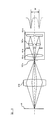
以下、本発明の実施形態を図面に基づいて説明する。図1は、本実施形態に係る一眼レフデジタルカメラ1を示すブロック図であり、本発明の撮像装置に関する構成以外のカメラの一般的構成については、その図示と説明を一部省略する。
Hereinafter, embodiments of the present invention will be described with reference to the drawings. FIG. 1 is a block diagram showing a single-lens reflex
図1に示すように、本実施形態の一眼レフデジタルカメラ1(以下、単にカメラ1という。)は、カメラ本体100とレンズ鏡筒200とを備え、カメラ本体100とレンズ鏡筒200とは着脱可能に結合される。
As shown in FIG. 1, the single-lens reflex digital camera 1 (hereinafter simply referred to as camera 1) of the present embodiment includes a
レンズ鏡筒200には、レンズ211,212,213、および絞り220を含む撮影光学系が内蔵されている。
The
フォーカスレンズ212は、レンズ鏡筒200の光軸L1に沿って移動可能に設けられ、エンコーダ260によってその位置が検出されつつレンズ駆動モータ230によってその位置が調節される。
The
このフォーカスレンズ212の光軸L1に沿う移動機構の具体的構成は特に限定されない。一例を挙げれば、レンズ鏡筒200に固定された固定筒に回転可能に回転筒を挿入し、この回転筒の内周面にヘリコイド溝(螺旋溝)を形成するとともに、フォーカスレンズ212を固定するレンズ枠の端部をヘリコイド溝に嵌合させる。そして、レンズ駆動モータ230によって回転筒を回転させることで、レンズ枠に固定されたフォーカスレンズ212が光軸L1に沿って直進移動することになる。なお、レンズ鏡筒200にはフォーカスレンズ212以外のレンズ211,213が設けられているが、ここではフォーカスレンズ212を例に挙げて本実施形態を説明する。
The specific configuration of the moving mechanism along the optical axis L1 of the
上述したようにレンズ鏡筒200に対して回転筒を回転させることによりレンズ枠に固定されたフォーカスレンズ212は光軸L1方向に直進移動するが、その駆動源としてのレンズ駆動モータ230がレンズ鏡筒200に設けられている。レンズ駆動モータ230と回転筒とは、たとえば複数の歯車からなる変速機で連結され、レンズ駆動モータ230の駆動軸を何れか一方向へ回転駆動すると所定のギヤ比で回転筒に伝達され、そして、回転筒が何れか一方向へ回転することで、レンズ枠に固定されたフォーカスレンズ212が光軸L1の何れかの方向へ直進移動することになる。なお、レンズ駆動モータ230の駆動軸が逆方向に回転駆動すると、変速機を構成する複数の歯車も逆方向に回転し、フォーカスレンズ212は光軸L1の逆方向へ直進移動することになる。
As described above, the
フォーカスレンズ212の位置はエンコーダ260によって検出される。既述したとおり、フォーカスレンズ212の光軸L1方向の位置は回転筒の回転角に相関するので、たとえばレンズ鏡筒200に対する回転筒の相対的な回転角を検出すれば、その位置を求めることができる。
The position of the
本実施形態のエンコーダ260としては、回転筒の回転駆動に連結された回転円板の回転をフォトインタラプタなどの光センサで検出して、回転数に応じたパルス信号を出力するものや、固定筒と回転筒の何れか一方に設けられたフレキシブルプリント配線板の表面のエンコーダパターンに、何れか他方に設けられたブラシ接点を接触させ、回転筒の移動量(回転方向でも光軸方向の何れでもよい)に応じた接触位置の変化を検出回路で検出するものなどを用いることができる。
As the
フォーカスレンズ212は、上述した回転筒の回転によってカメラ本体100側の端部(至近端ともいう)から被写体側の端部(無限遠端ともいう)までの間を光軸L1方向に移動することができる。ちなみに、エンコーダ260で検出されたフォーカスレンズ212の現在位置情報は、レンズ制御部250を介して後述するカメラ制御部170へ送出される。そして、フォーカスレンズ212の位置情報に基づいて算出されたフォーカスレンズ212の駆動量が、カメラ制御部170からレンズ制御部250を介して送出され、これに基づいて、レンズ駆動モータ230は駆動する。
The
絞り220は、上記撮影光学系を通過して、カメラ本体100に備えられた撮像素子110に至る光束の光量を制限するとともにボケ量を調整するために、光軸L1を中心にした開口径が調節可能に構成されている。絞り220による開口径の調節は、たとえば自動露出モードにおいて演算された適切な開口径が、カメラ制御部170からレンズ制御部250を介して絞り駆動部240へ送信されることにより行われる。また、開口径の調節は、カメラ本体100に設けられた操作部150を介したマニュアル操作により、設定された開口径がカメラ制御部170からレンズ制御部250を介して絞り駆動部240へ送信されることによっても行われる。なお、絞り220の開口径は図示しない絞り開口センサにより検出され、レンズ制御部250で現在の開口径が認識される。
The
一方、カメラ本体100は、被写体からの光束を撮像素子110、ファインダ135、測光センサ137および焦点検出モジュール161へ導くためのミラー系120を備える。このミラー系120は、回転軸123を中心にして被写体の観察位置と撮像位置との間で所定角度だけ回転するクイックリターンミラー121と、このクイックリターンミラー121に軸支されてクイックリターンミラー121の回動に合わせて回転するサブミラー122とを備える。図1においては、ミラー系120が被写体の観察位置にある状態を実線で示し、被写体の撮像位置にある状態を二点鎖線で示す。
On the other hand, the
ミラー系120は、被写体の観察位置にある状態では光軸L1の光路上に挿入される一方で、被写体の撮像位置にある状態では光軸L1の光路から退避するように回転する。
The
クイックリターンミラー121はハーフミラーで構成され、被写体の観察位置にある状態では、被写体からの光束(光軸L1)の一部の光束(光軸L2,L3)を当該クイックリターンミラー121で反射してファインダ135および測光センサ137に導き、一部の光束(光軸L4)を透過させてサブミラー122へ導く。これに対して、サブミラー122は全反射ミラーで構成され、クイックリターンミラー121を透過した光束(光軸L4)を焦点検出モジュール161へ導く。
The
したがって、ミラー系120が観察位置にある場合は、被写体からの光束(光軸L1)はファインダ135、測光センサ137および焦点検出モジュール161へ導かれ、撮影者により被写体が観察されるとともに、露出演算やフォーカスレンズ212の焦点調節状態の検出が実行される。そして、撮影者がレリーズボタンを全押しするとミラー系120が撮影位置に回動し、被写体からの光束(光軸L1)は全て撮像素子110へ導かれ、撮影した画像データを図示しないメモリに保存する。
Therefore, when the
クイックリターンミラー121で反射された被写体からの光束(光軸L2)は、撮像素子110と光学的に等価な面に配置された焦点板131に結像し、ペンタプリズム133と接眼レンズ134とを介して観察可能になっている。このとき、透過型液晶表示器132は、焦点板131上の被写体像に焦点検出エリアマークなどを重畳して表示するとともに、被写体像外のエリアにシャッター速度、絞り値、撮影枚数などの撮影に関する情報を表示する。これにより、撮影者は、撮影準備状態において、ファインダ135を通して被写体およびその背景ならびに撮影関連情報などを観察することができる。
The light flux (optical axis L2) from the subject reflected by the
また、接眼レンズ134の近傍には、測光用レンズ136と測光センサ137とが設けられ、焦点板131に結像した被写体光の一部を受光する。
In addition, a
測光センサ137は、二次元カラーCCDイメージセンサなどで構成され、撮影の際の露出値を演算するため、撮影画面を複数の領域に分割して領域ごとの輝度に応じた測光信号を出力する。測光センサ137で検出された信号はカメラ制御部170へ出力され、自動露出制御や特定被写体の検出に用いられる。
The
焦点検出モジュール161は、被写体光を用いた位相差検出方式による自動合焦制御を実行するための焦点検出素子であり、サブミラー122で反射した光束(光軸L4)の、撮像素子110の撮像面と光学的に等価な位置に固定されている。
The focus detection module 161 is a focus detection element for executing automatic focusing control by a phase difference detection method using subject light, and the imaging surface of the
図2は、図1に示す焦点検出モジュール161の構成例を示す図である。本実施形態の焦点検出モジュール161は、コンデンサレンズ161a、一対の開口が形成された絞りマスク161b、一対の再結像レンズ161cおよび一対のラインセンサ161dを有する。また、図示していないが、本実施形態のラインセンサ161dは、撮像光学系の予定焦点面近傍に配置されたマイクロレンズと、このマイクロレンズに対して配置された光電変換素子とを有する画素が複数配列された画素列を備えている。フォーカスレンズ212の射出瞳の異なる一対の領域を通る一対の光束を、一対のラインセンサ161dに配列された各画素で受光することで、一対の像信号を取得することができる。そして、一対のラインセンサ161dで取得した一対の像信号の位相ずれを、後述する相関演算によって求めることにより焦点調節状態を検出することができる。
FIG. 2 is a diagram illustrating a configuration example of the focus detection module 161 illustrated in FIG. The focus detection module 161 of this embodiment includes a
例えば、図2に示すように、被写体Pが撮像素子110の等価面(予定結像面)161eで結像すると合焦状態となるが、フォーカスレンズ212が光軸L1方向に移動することで、結像点が等価面161eより被写体側にずれたり(前ピンと称される)、カメラボディ側にずれたりすると(後ピンと称される)、ピントずれの状態となる。
For example, as shown in FIG. 2, when the subject P is imaged on the equivalent plane (planned imaging plane) 161e of the
なお、被写体Pの結像点が等価面161eより被写体側にずれると、一対のラインセンサ161dで検出される一対の像信号の間隔Wが、合焦状態の間隔Wと比べて短くなり、逆に被写体Pの結像点がカメラ本体100側にずれると、一対のラインセンサ161dで検出される一対の像信号の間隔Wが、合焦状態の間隔Wに比べて長くなる。
When the imaging point of the subject P is shifted from the
すなわち、合焦状態では一対のラインセンサ161dで検出される像信号が、それぞれのラインセンサの中心に対して重なるが、非合焦状態ではラインセンサの中心に対して像信号がずれ、すなわち位相差が生じるので、この位相差(ずれ量)に応じた量だけフォーカスレンズ212を移動させることでピントを合わせることができる。
That is, in the in-focus state, the image signals detected by the pair of
AF−CCD制御部162は、オートフォーカスモードにおいて、焦点検出モジュール161のラインセンサ161dのゲインや蓄積時間などの蓄積条件を制御するものであり、焦点検出モジュール161に備えられた複数対のラインセンサ161dにて検出された像信号を各焦点検出エリアAFPに対応させて読み出し、読み出した像信号をカメラ制御部170およびデフォーカス演算部163へ出力する。
The AF-CCD control unit 162 controls accumulation conditions such as gain and accumulation time of the
デフォーカス演算部163は、AF−CCD制御部162から送られてきた各焦点検出エリアAFPに対応した一対の像信号のずれ量をデフォーカス量に変換し、これをレンズ駆動量演算部164へ出力する。 The defocus calculation unit 163 converts the shift amount of the pair of image signals corresponding to each focus detection area AFP sent from the AF-CCD control unit 162 into a defocus amount, and converts this to the lens drive amount calculation unit 164. Output.
レンズ駆動量演算部164は、デフォーカス演算部163から送られてきたデフォーカス量に基づいて、当該デフォーカス量に応じたレンズ駆動量Δdを演算し、これをレンズ駆動制御部165へ出力する。 Based on the defocus amount sent from the defocus calculation unit 163, the lens drive amount calculation unit 164 calculates a lens drive amount Δd corresponding to the defocus amount, and outputs this to the lens drive control unit 165. .
レンズ駆動制御部165は、レンズ駆動量演算部164から送られてきたレンズ駆動量Δdに基づいて、レンズ駆動モータ230を駆動し、フォーカスレンズ212の位置を調整する。
The lens drive controller 165 drives the lens drive motor 230 based on the lens drive amount Δd sent from the lens drive amount calculator 164 and adjusts the position of the
撮像素子110は、カメラ本体100の、被写体からの光束の光軸L1上であって、レンズ211,212,213を含む撮影光学系の予定焦点面に設けられ、その前面にシャッター111が設けられている。この撮像素子110は、複数の光電変換素子が二次元に配置されたものであって、二次元CCDイメージセンサ、MOSセンサまたはCIDなどのデバイスから構成することができる。撮像素子110で光電変換された画像信号は、カメラ制御部170で画像処理されたのち図示しないメモリに保存される。なお、撮影画像を格納するメモリは内蔵型メモリやカード型メモリなどで構成することができる。
The
カメラ制御部170はマイクロプロセッサとメモリなどの周辺部品から構成され、撮像素子110から画像信号を読み出すとともに、必要に応じて所定の情報処理を施して、画像データを生成し、生成した画像データを、図示しないメモリに記憶させる。この他にも、カメラ制御部170は、撮影画像情報の補正、レンズ鏡筒200の焦点調節状態の検出、および絞り調節状態の検出など、カメラ1全体の制御を司る。
The
操作部150は、例えば、シャッターレリーズボタン、動画撮影を開始するためのスイッチ、および、カメラ1の各種動作モードを設定するためのモード設定スイッチなどを備えており、操作部150により、たとえば、オートフォーカスモード/マニュアルフォーカスモードの切換ができるようになっている。また、シャッターレリーズボタンのスイッチは、ボタンの半押しでONとなる第1スイッチSW1と、ボタンの全押しでONとなる第2スイッチSW2とを含む。
The
さらに、本実施形態では、図3に示すように、カメラ本体100の背面に、操作部150として、2つのスイッチ151,152が設けられている。図3は、本実施形態に係るカメラ本体100の背面図である。なお、これらのスイッチ151,152の動作の詳細については後述する。
Further, in the present embodiment, as shown in FIG. 3, two
ディスプレイ180は、図3に示すように、カメラ本体100の背面に設けられ、撮像素子110により得られた画像信号に基づくスルー画像を、ディスプレイ180に備える画面上に表示する。
As shown in FIG. 3, the
次に、図4を参照して、本実施形態に係るカメラ1の動作を説明する。図4は、本実施形態に係るカメラ1の動作を示すフローチャートである。以下においては、たとえば、操作部150を介して、撮影者により動画撮影モードが設定されている場面におけるカメラ1の動作を説明する。なお、以下に説明する動作は、動画撮影ボタンがオンされることにより開始される。
Next, the operation of the
ステップS101では、カメラ制御部170により、測光センサ137から被写体認識用の画像信号が取得され、取得された画像信号に基づいて、特定被写体の検出が行われる。ここで、図5は、ディスプレイ180の画面上に表示される画像の一例である。図5に示す例では、特定被写体として人物の顔を検出しており、カメラ制御部170は、人物の顔のテンプレート画像を用いてテンプレートマッチングを行うことで、撮影画像中から人物の顔を特定被写体として検出する。なお、特定被写体は、人物の顔に限定されず、たとえば、動物の顔などを特定被写体として検出してもよい。
In step S101, the
ステップS102では、カメラ制御部170により、ステップS101で検出された特定被写体に認識枠52が重畳され、図5に示すように、特定被写体に認識枠52を重畳したスルー画像が、ディスプレイ180に備える画面に表示される。たとえば、図5に示す例では、4人の顔領域A,B,C,Dが特定被写体として検出されており、検出された4人の顔領域A,B,C,Dに対して、各人の顔領域の位置に合わせた認識枠52が重畳される。
In step S102, the
そして、ステップS103では、カメラ制御部170により、特定被写体の中から対象被写体が選択されたか否かの判断が行われる。対象被写体とは、ステップS101で検出された特定被写体のうち、撮影者がピントを合わせようとする被写体である。たとえば、本実施形態では、図5に示すように、ディスプレイ180に備える画面のうち、左側部分にスルー画像が表示されるとともに、右側部分にステップS101で検出された4人の顔領域A,B,C,D(特定被写体)が表示される。撮影者は、たとえば、操作部150のうち図3に示すスイッチ151を操作することで、この4人の顔領域A,B,C,D(特定被写体)のうち、ピントを合わせたい顔領域を選択することができ、シャッターレリーズボタンを押下して決定することで、選択した顔領域を対象被写体として決定することができる。そして、対象被写体が選択されたと判断された場合は、ステップS104に進み、カメラ制御部170により、撮影者により選択された対象被写体の特定が行われる。一方、対象被写体が選択されていない場合には、撮影者により対象被写体が選択されるまで、ステップS103で待機する。
In step S103, the
ステップS105では、カメラ制御部170により、対象被写体にピントを合わせる際のフォーカスレンズ212の駆動速度が設定されたか否かの判断が行われる。本実施形態では、図3に示すように、カメラ本体100の背面にスイッチ152が設けられており、撮影者は、このスイッチ152を操作することで、対象被写体にピントを合わせる際のフォーカスレンズ212の駆動速度を設定することができる。たとえば、図3に示す例では、スイッチ152により3段階の駆動速度が設定可能となっている。すなわち、図3に示す例では、スイッチ152は3つのスイッチから構成されており、対象被写体にピントを合わせる際のレンズ駆動速度を、「低速」、「中速」、「高速」のいずれかに設定することが可能となっている。そして、スイッチ152を介して、撮影者が対象被写体にピントを合わせる際のレンズ駆動速度を設定した場合に、カメラ制御部170は、対象被写体にピントを合わせる際のフォーカスレンズ212の駆動速度が設定されたと判断する。
In step S105, the
ステップS105において、フォーカスレンズ212の駆動速度が設定されたと判断された場合には、ステップS106に進み、カメラ制御部170により、撮影者により設定されたフォーカスレンズ212の駆動速度の取得が行われる。一方、フォーカスレンズ212の駆動速度が設定されていないと判断された場合には、、フォーカスレンズ212の駆動速度が設定されるまで、このステップS105で待機する。
If it is determined in step S105 that the drive speed of the
なお、図3に示すスイッチ152により設定される「低速」、「中速」、「高速」の3つの速度は、特に限定されないが、たとえば、対象被写体にゆっくりとピントを合わせることができ、これにより、映画的な演出効果が得られる動画像を撮影可能なフォーカスレンズ212の駆動速度を「低速」とすることができ、一方、ピントが合っている被写体を素早く変更することができるフォーカスレンズ212の駆動速度を「高速」とすることができ、「低速」と「高速」との中間の速度を「中速」とすることができる。
The three speeds “low speed”, “medium speed”, and “high speed” set by the
ステップS107では、光学系の焦点状態を検出するために、焦点検出演算が行われる。具体的には、まず、焦点検出モジュール161のラインセンサ161dにより電荷の蓄積が行われ、ラインセンサ161dで蓄積された信号情報が、デフォーカス演算部163により読み出される。本実施形態では、撮影画面内に複数の焦点検出エリアAFPが設定されており、デフォーカス演算部163は、撮影者により選択された対象被写体に対応する焦点検出エリアAFPの信号情報を読み出し、読み出した信号情報に基づいて、対象被写体に対応する焦点検出エリアAFPのデフォーカス量の演算を行う。
In step S107, a focus detection calculation is performed to detect the focus state of the optical system. Specifically, first, charges are accumulated by the
ステップS108では、撮影者により設定されたレンズ駆動速度で、フォーカスレンズ212を駆動させる処理が実行される。具体的には、まず、レンズ駆動量演算部164により、対象被写体に対応する焦点検出エリアAFPのデフォーカス量に基づいて、フォーカスレンズ212を、対象被写体に対応する合焦位置まで駆動させるために必要となるレンズ駆動量の演算が行われる。そして、算出されたレンズ駆動量が、レンズ制御部250を介して、フォーカスレンズ駆動モータ230に送出され、フォーカスレンズ駆動モータ230により、算出されたレンズ駆動量に基づくフォーカスレンズ212の駆動が行われる。
In step S108, a process for driving the
また、本実施形態では、撮影者により設定されたフォーカスレンズ212の駆動速度(ステップS106で取得された対象被写体にピントを合わせる際のレンズ駆動速度)が、レンズ制御部250を介して、フォーカスレンズ駆動モータ230に送出され、フォーカスレンズ駆動モータ230により、撮影者により設定されたフォーカスレンズ212の駆動速度で、フォーカスレンズ212が駆動されることとなる。たとえば、図3に示すスイッチ152を介して、撮影者により、対象被写体にピントを合わせる際のレンズ駆動速度が「低速」に設定された場合には、撮影者により設定された「低速」で、フォーカスレンズ212が駆動されることとなる。
In this embodiment, the driving speed of the
そして、ステップS109では、カメラ制御部170により、合焦判定が行われる。本実施形態では、たとえば、ステップS107で算出されたデフォーカス量が所定値以下である場合に、合焦と判定され、ステップS110に進み、フォーカスレンズ212の駆動が停止される。一方、デフォーカス量が所定値を超え、合焦と判定されない場合は、ステップS107に戻り、合焦と判定されるまで、焦点検出演算を繰り返しながら、撮影者により設定されたレンズ駆動速度でフォーカスレンズ212の駆動が行われる。
In step S109, the
次に、図6および図7を参照して、本実施形態に係るカメラ1の動作例を説明する。ここで、図6では、図6(A)に示すように、無限遠側に位置する樹木にピントが合っている状態から、図6(B)に示すように、至近側に位置する人物Xにゆっくりとピントを合わせることで、映画的な演出効果が得られる動画像を撮影する場面を例示している。たとえば、至近側に位置する人物Xにゆっくりとピントを合わせるために、撮影者は、図5に示すスイッチ151により、人物Xを対象被写体として選択するとともに、図5に示すスイッチ152により、対象被写体にピントを合わせる際のフォーカスレンズ212の駆動速度を「低速」に設定する。これにより、カメラ本体100において、対象被写体として人物Xが特定されるとともに(ステップS104)、対象被写体にピントを合わせる際のフォーカスレンズ212の駆動速度が「低速」として取得される(ステップS106)。そして、カメラ制御部170は、撮影者により設定されたフォーカスレンズ212の駆動速度、すなわち「低速」で、ゆっくりとフォーカスレンズ212を駆動させながら(ステップS108)、動画像を撮影し、最終的に、対象被写体である人物Xに合焦するフォーカスレンズ212のレンズ位置まで、フォーカスレンズ212を駆動させる(ステップS109,S110)。このように、本実施形態では、撮影者が、ピントを合わせたい対象被写体を選択し、ピントを合わせる際のフォーカスレンズ212の駆動速度を、たとえば「低速」に設定するだけで、図6に示すように、背景の樹木から人物Xへとゆっくりとピントを合わせることができ、映画的な演出効果が得られる動画像を容易に撮影することができる。
Next, an operation example of the
一方、図7では、スポーツシーンを撮影する場面を例示しており、図7(A)に示すように、前方を走行する人物Yにピントが合っている状態から、図7(B)に示すように、後方を走行する人物Zに素早くピントを合わせることで、撮影の対象となる被写体を素早く切り替える場面を例示している。たとえば、後方を走行する人物Zに素早くピントを合わせるために、撮影者は、図5に示すスイッチ151により、人物Zを対象被写体として選択するとともに、また、図5に示すスイッチ152により、ピントを合わせる際のフォーカスレンズ212の駆動速度を「高速」に設定する。これにより、カメラ本体100において、対象被写体として人物Zが特定されるとともに(ステップS104)、対象被写体にピントを合わせる際のフォーカスレンズ212の駆動速度が「高速」として取得される(ステップS106)。そして、カメラ制御部170は、撮影者により設定されたフォーカスレンズ212の駆動速度、すなわち「高速」で、素早くフォーカスレンズ212を駆動させながら(ステップS108)、動画像を撮影し、最終的に、対象被写体である人物Zに合焦するフォーカスレンズ212のレンズ位置まで、フォーカスレンズ212を駆動させる(ステップS109,S110)。このように、本実施形態では、撮影者が、ピントを合わせたい対象被写体を選択し、ピントを合わせる際のフォーカスレンズ212の駆動速度を、たとえば「高速」に設定するだけで、図7に示すように、異なる被写体に素早くピントを合わせることができる。また、このように、本実施形態では、撮影シーンに応じて、撮影者が対象被写体にピントを合わせる際のフォーカスレンズ212の駆動速度を変えることで、撮影シーンに応じた良好な動画像を撮影することができる。
On the other hand, FIG. 7 illustrates a scene where a sports scene is photographed. As shown in FIG. 7A, the person Y traveling in front is in focus and is shown in FIG. 7B. In this manner, the scene in which the subject to be photographed is quickly switched by quickly focusing on the person Z traveling behind is illustrated. For example, in order to quickly focus on the person Z traveling behind, the photographer selects the person Z as a target subject using the
以上のように、本実施形態では、撮影者が選択した被写体を対象被写体として特定し、撮影者により設定されたレンズ駆動速度で、対象被写体に対する焦点調節を行う。これにより、本実施形態では、たとえば、撮影者により対象被写体にピントを合わせる際のレンズ駆動速度が「低速」に設定された場合には、対象被写体にゆっくりとピントを合わせて、映画的な演出効果が得られる動画像の撮影を容易に行うことができるとともに、撮影者により対象被写体にピントを合わせる際のレンズ駆動速度が「高速」に設定された場合には、撮影者が選択した対象被写体に素早くピントを合わせることで、撮影の対象とする被写体を素早く切り替えることができる。 As described above, in the present embodiment, the subject selected by the photographer is specified as the target subject, and the focus adjustment for the target subject is performed at the lens driving speed set by the photographer. Thus, in the present embodiment, for example, when the lens driving speed when the photographer focuses on the target subject is set to “low speed”, the subject subject is slowly focused and a cinematic effect is achieved. It is possible to easily shoot moving images that are effective, and the target subject selected by the photographer is selected when the lens drive speed is set to "high speed" when the photographer focuses on the subject subject. By quickly focusing on the subject, it is possible to quickly switch the subject to be photographed.
以上説明した実施形態は、本発明の理解を容易にするために記載されたものであって、本発明を限定するために記載されたものではない。したがって、上記の実施形態に開示された各要素は、本発明の技術的範囲に属する全ての設計変更や均等物をも含む趣旨である。 The embodiment described above is described for facilitating understanding of the present invention, and is not described for limiting the present invention. Therefore, each element disclosed in the above embodiment is intended to include all design changes and equivalents belonging to the technical scope of the present invention.
たとえば、上述した実施形態では、図5に示すスイッチ152により、対象被写体にピントを合わせる際のフォーカスレンズ212の駆動速度を設定する構成を例示したが、この構成に限定されず、たとえば、図8に示すように、ダイヤル153を用いて、フォーカスレンズ212の駆動速度を設定する構成としてもよい。また、図5に示すスイッチ152に、撮影者が予め決定したレンズ駆動速度を記憶させておき、対象被写体にピントを合わせる際に、スイッチ152を用いて、撮影者が予め決定したレンズ駆動速度でフォーカスレンズ212を駆動させる構成としてもよい。
For example, in the above-described embodiment, the configuration in which the driving speed of the
また、上述し実施形態では、図5に示すスイッチ151により、対象被写体を選択する構成を例示したが、この構成に限定されず、たとえば、ディスプレイ180にタッチパネルを備え、撮影者が、特定被写体の中からピントを合わせたい被写体をタップすることで、対象被写体を選択する構成としてもよい。また、この場合、タップの回数で対象被写体にピントを合わせる際のフォーカスレンズ212の駆動速度を設定する構成としてもよい。たとえば、タッチパネルを2度連続してタップした場合には、対象被写体にピントを合わせる際のフォーカスレンズ212の駆動速度を「高速」に設定し、タッチパネルを1度のみタップした場合には、対象被写体にピントを合わせる際のフォーカスレンズ212の駆動速度を「低速」に設定する構成としてもよい。
Further, in the above-described embodiment, the configuration in which the target subject is selected by the
さらに、上述した実施形態では、動画撮影を行う場合に、撮影者が設定したレンズ駆動速度で対象被写体にピントを合わせる構成を例示したが、たとえば、スルー画像を撮影する際に、撮影者が設定したレンズ駆動速度で対象被写体にピントを合わせる構成としてもよい。 Furthermore, in the above-described embodiment, the configuration in which the target subject is focused at the lens driving speed set by the photographer when moving image shooting is illustrated. However, for example, the photographer sets the focus when shooting a through image. A configuration may be adopted in which the subject is focused at the lens driving speed.
また、上述した実施形態では、図5に示すように、人物の顔領域などの特定被写体を検出し、検出した特定被写体のうち撮影者が選択した対象被写体にピントを合わせる構成を例示したが、この構成に限定されず、たとえば、撮影者が無限遠側の背景や至近側の被写体を選択した場合には、無限遠側の背景や至近側の被写体にピントを合わせる構成としてもよい。この場合、たとえば図5に示す画面例の右側部分に、特定被写体(人物の顔領域A,B,C,D)とともに、背景などの画像を表示することで、撮影者が、無限遠側の背景や至近側の被写体を対象被写体として選択することができる。 In the above-described embodiment, as illustrated in FIG. 5, a specific subject such as a person's face area is detected, and the configuration in which the subject selected by the photographer among the detected specific subjects is focused is exemplified. For example, when the photographer selects a background on the infinity side or a subject on the near side, the subject may be focused on the background on the infinity side or the subject on the near side. In this case, for example, by displaying an image such as a background together with a specific subject (a person's face area A, B, C, D) on the right side of the screen example shown in FIG. A background or a near subject can be selected as a subject.
さらに、上述した実施形態では、対象被写体に合焦するレンズ位置までフォーカスレンズ212を駆動させる構成を例示したが、この構成に限定されず、たとえば、対象被写体が選択された場合に、対象被写体が存在する位置よりも所定距離だけ至近側あるいは無限遠側の位置にピントを合わせる構成としてもよい。これにより、対象被写体に一度ピントが合った後に、対象被写体がぼけるような演出効果が得られた動画像を撮影することができる。
Furthermore, in the above-described embodiment, the configuration in which the
加えて、上述した実施形態では、撮影者により設定されたレンズ駆動速度に基づいて、フォーカスレンズ212を、対象被写体に合焦するレンズ位置まで駆動させる構成を例示したが、この構成に限定されず、たとえば、操作部150を介して、撮影者により、フォーカスレンズ212を対象被写体に合焦するレンズ位置に移動させるための時間が入力された場合には、フォーカスレンズ212を撮影者により入力された時間で対象被写体に合焦するレンズ位置まで移動させることができるレンズ駆動速度を算出し、算出したレンズ駆動速度で、フォーカスレンズ212を対象被写体に合焦するレンズ位置まで駆動させる構成としてもよい。
In addition, in the above-described embodiment, the configuration in which the
また、上述した実施形態では、一対のラインセンサ161dで検出される像信号のずれ量(位相差)に基づいて、光学系の焦点状態を検出する構成を例示したが、この構成に限定されず、たとえば、フォーカスレンズ212を所定のサンプリング間隔(距離)で駆動さながら、それぞれのレンズ位置で、撮像素子110から得られた画像信号に基づいて焦点評価値を算出することで、焦点評価値が最大となるフォーカスレンズ212のレンズ位置を合焦位置として求める、コントラスト検出方式の焦点検出を行う構成としてもよい。
In the above-described embodiment, the configuration in which the focus state of the optical system is detected based on the shift amount (phase difference) of the image signal detected by the pair of
さらに、上述した実施形態では、測光センサ137により測光を行う構成を例示したが、この構成に限定されるものではなく、たとえば、撮像素子110により測光を行う構成としてもよい。
Furthermore, in the above-described embodiment, the configuration in which photometry is performed by the
なお、上述した実施形態のカメラ1は特に限定されず、例えば、デジタルビデオカメラ、レンズ交換式のデジタルカメラ、レンズ一体型のデジタルカメラ、携帯電話用のカメラなどのその他の光学機器に本発明を適用してもよい。
The
1…一眼レフデジタルカメラ
100…カメラ本体
110…撮像素子
137…測光センサ
150…操作部
151…対象被写体選択用のスイッチ
152…レンズ駆動速度設定用のスイッチ
161…焦点検出モジュール
170…カメラ制御部
180…ディスプレイ
200…レンズ鏡筒
DESCRIPTION OF
Claims (5)
前記被写体検出部により検出された被写体の中から対象被写体を選択する選択部と、
前記光学系の焦点状態を検出する焦点検出部と、
前記焦点検出部による焦点検出結果に基づいて、前記焦点調節レンズを光軸方向に駆動させることで、前記光学系の焦点調節を行う焦点調節部と、
前記焦点調節レンズを前記対象被写体に合焦するレンズ位置まで駆動させる際の前記焦点調節レンズの駆動速度を、撮影者が入力可能な入力部と、
前記入力部を介して、撮影者により入力された前記焦点調節レンズの駆動速度を取得する取得部と、を備え、
前記焦点調節部は、前記対象被写体が選択された場合に、前記撮影者により設定された焦点調節レンズの駆動速度で、前記焦点調節レンズを、前記対象被写体に合焦するレンズ位置まで駆動させることを特徴とする撮像装置。 A subject detection unit for detecting a subject based on a light beam from an optical system having a focus adjustment lens;
A selection unit for selecting a target subject from the subjects detected by the subject detection unit;
A focus detection unit for detecting a focus state of the optical system;
A focus adjustment unit that performs focus adjustment of the optical system by driving the focus adjustment lens in an optical axis direction based on a focus detection result by the focus detection unit;
An input unit that allows a photographer to input a driving speed of the focus adjustment lens when driving the focus adjustment lens to a lens position that focuses on the target subject;
An acquisition unit that acquires the driving speed of the focus adjustment lens input by the photographer via the input unit;
When the target subject is selected, the focus adjustment unit drives the focus adjustment lens to a lens position that focuses on the target subject at a driving speed of the focus adjustment lens set by the photographer. An imaging apparatus characterized by the above.
動画撮影モードを設定可能なモード設定部をさらに備え、
前記焦点調節部は、前記動画撮影モードに設定されている場合において、前記対象被写体が選択された場合に、前記撮影者により設定された焦点調節レンズの駆動速度で、前記焦点調節レンズを、前記対象被写体に合焦するレンズ位置まで駆動させること特徴とする撮像装置。 The imaging apparatus according to claim 1,
It further includes a mode setting section that can set the movie shooting mode,
In the case where the moving image shooting mode is set, the focus adjustment unit moves the focus adjustment lens at the driving speed of the focus adjustment lens set by the photographer when the target subject is selected. An imaging apparatus that is driven to a lens position that focuses on a target subject.
前記焦点検出部は、前記光学系による像面のずれ量を検出することで、前記光学系の焦点検出を行う位相差検出方式の焦点検出が可能であることを特徴とする撮像装置。 The imaging apparatus according to claim 1, wherein:
The imaging apparatus according to claim 1, wherein the focus detection unit is capable of performing focus detection by a phase difference detection method that performs focus detection of the optical system by detecting an amount of image plane shift by the optical system.
前記焦点調節部は、前記対象被写体が選択された場合に、前記焦点調節レンズを前記対象被写体に合焦するレンズ位置まで駆動させた後に、前記焦点調節レンズを、前記対象被写体よりも所定距離だけ至近側または無限遠側の位置まで駆動させることを特徴とする撮像装置。 The imaging apparatus according to any one of claims 1 to 3,
When the target subject is selected, the focus adjustment unit drives the focus adjustment lens to a lens position that focuses on the target subject, and then moves the focus adjustment lens by a predetermined distance from the target subject. An image pickup apparatus that is driven to a position on the near side or infinity side.
前記入力部は、前記焦点調節レンズの駆動を開始してから前記対象被写体に合焦するまでの時間を入力可能であり、
前記焦点調節部は、前記入力部を介して、撮影者により前記対象被写体に合焦するまでの時間が入力された場合には、前記対象被写体が選択された場合に、前記撮影者に入力された時間で前記対象被写体に合焦できる前記焦点調節レンズの駆動速度を算出し、算出した駆動速度で、前記焦点調節レンズを、前記対象被写体に合焦するレンズ位置まで駆動させることを特徴とする撮像装置。 The imaging apparatus according to any one of claims 1 to 4,
The input unit is capable of inputting a time from the start of driving the focus adjustment lens to focusing on the target subject.
The focus adjustment unit is input to the photographer when the target subject is selected when a time until focusing on the target subject is input by the photographer via the input unit. The driving speed of the focus adjustment lens that can focus on the target subject in a predetermined time is calculated, and the focus adjustment lens is driven to the lens position that focuses on the target subject at the calculated drive speed. Imaging device.
Priority Applications (1)
| Application Number | Priority Date | Filing Date | Title |
|---|---|---|---|
| JP2012056181A JP2013190569A (en) | 2012-03-13 | 2012-03-13 | Imaging apparatus |
Applications Claiming Priority (1)
| Application Number | Priority Date | Filing Date | Title |
|---|---|---|---|
| JP2012056181A JP2013190569A (en) | 2012-03-13 | 2012-03-13 | Imaging apparatus |
Publications (1)
| Publication Number | Publication Date |
|---|---|
| JP2013190569A true JP2013190569A (en) | 2013-09-26 |
Family
ID=49390900
Family Applications (1)
| Application Number | Title | Priority Date | Filing Date |
|---|---|---|---|
| JP2012056181A Pending JP2013190569A (en) | 2012-03-13 | 2012-03-13 | Imaging apparatus |
Country Status (1)
| Country | Link |
|---|---|
| JP (1) | JP2013190569A (en) |
Cited By (1)
| Publication number | Priority date | Publication date | Assignee | Title |
|---|---|---|---|---|
| WO2022091464A1 (en) * | 2020-10-29 | 2022-05-05 | ソニーグループ株式会社 | Information processing device, information processing method, and program |
-
2012
- 2012-03-13 JP JP2012056181A patent/JP2013190569A/en active Pending
Cited By (2)
| Publication number | Priority date | Publication date | Assignee | Title |
|---|---|---|---|---|
| WO2022091464A1 (en) * | 2020-10-29 | 2022-05-05 | ソニーグループ株式会社 | Information processing device, information processing method, and program |
| US12418715B2 (en) | 2020-10-29 | 2025-09-16 | Sony Group Corporation | Information processing device, information processing method, and program |
Similar Documents
| Publication | Publication Date | Title |
|---|---|---|
| JP5195506B2 (en) | Imaging apparatus and image composition method | |
| JP4766133B2 (en) | Imaging device | |
| JP5206292B2 (en) | Imaging apparatus and image recording method | |
| JP5776191B2 (en) | Focus detection apparatus and imaging apparatus | |
| JP6398250B2 (en) | Focus detection device | |
| JP4992761B2 (en) | LENS DRIVE DEVICE AND IMAGING DEVICE | |
| JP5966299B2 (en) | FOCUS DETECTION DEVICE AND IMAGING DEVICE HAVING THE SAME | |
| JP5458860B2 (en) | Imaging device | |
| JP2015118231A (en) | Imaging device | |
| JP5402189B2 (en) | Focus adjustment device and imaging device provided with the same | |
| JP2013190569A (en) | Imaging apparatus | |
| JP6056208B2 (en) | Camera body and imaging device | |
| JP2013025129A (en) | Focus detection device and imaging apparatus | |
| JP5391587B2 (en) | Imaging device | |
| JP6699679B2 (en) | Imaging device | |
| JP5402129B2 (en) | Focus detection device, focus adjustment device, and imaging device | |
| JP5493470B2 (en) | Focus adjustment device and imaging device provided with the same | |
| JP6014977B2 (en) | Focus detector, camera body, and camera | |
| JP2012247723A (en) | Focus adjustment device and imaging apparatus | |
| JP2013083768A (en) | Focus detection device and imaging apparatus | |
| JP2013131851A (en) | Imaging apparatus | |
| JP5961979B2 (en) | Focus adjustment device and imaging device | |
| JP2012226246A (en) | Focus detector and imaging apparatus | |
| JP2015187662A (en) | Focus adjustment device and imaging device | |
| JP5115325B2 (en) | Lens barrel and imaging device |