JP2013190027A - Power transmission device - Google Patents
Power transmission device Download PDFInfo
- Publication number
- JP2013190027A JP2013190027A JP2012056594A JP2012056594A JP2013190027A JP 2013190027 A JP2013190027 A JP 2013190027A JP 2012056594 A JP2012056594 A JP 2012056594A JP 2012056594 A JP2012056594 A JP 2012056594A JP 2013190027 A JP2013190027 A JP 2013190027A
- Authority
- JP
- Japan
- Prior art keywords
- continuously variable
- fastening
- variable transmission
- power
- torque
- Prior art date
- Legal status (The legal status is an assumption and is not a legal conclusion. Google has not performed a legal analysis and makes no representation as to the accuracy of the status listed.)
- Pending
Links
Images


Landscapes
- Transmission Devices (AREA)
- Control Of Transmission Device (AREA)
Abstract
【課題】ギアードニュートラル状態を実現すべくCVT22の変速比を操作するに際し、実際の変速比がギアードニュートラル状態を実現するうえで要求される値から僅かにずれる場合には、駆動輪14に過大なトルクが加わるおそれがあること。
【解決手段】シフトレンジがDレンジに切り替えられる場合、循環用クラッチ24を締結状態とし、エンジン20を起動させるとともに、CVT22の変速比を、ギアードニュートラル状態を実現できると認識されている変速比に操作する。この際、循環用クラッチ24の締結力を制限する。これに伴い、循環用クラッチ24の入力側および出力側に滑りが生じる場合、CVT22の変速比を、進行しようとする方向とは逆方向に駆動輪14を回転させる側に変更する。
【選択図】 図1When operating a gear ratio of a CVT to realize a geared neutral state, if the actual gear ratio slightly deviates from a value required for realizing the geared neutral state, the drive wheel is excessively large. There is a risk of applying torque.
When the shift range is switched to the D range, the circulating clutch 24 is engaged, the engine 20 is started, and the gear ratio of the CVT 22 is changed to a gear ratio that is recognized as being capable of realizing a geared neutral state. Manipulate. At this time, the fastening force of the circulation clutch 24 is limited. Accordingly, when slip occurs on the input side and the output side of the circulation clutch 24, the transmission ratio of the CVT 22 is changed to the side that rotates the drive wheels 14 in the direction opposite to the direction in which the CVT 22 tends to travel.
[Selection] Figure 1
Description
本発明は、無段変速装置の変速比の操作によって、駆動源の回転速度がゼロでない状況下、駆動輪の回転速度をゼロとするギアードニュートラル状態を実現可能な動力伝達装置に関する。 The present invention relates to a power transmission device capable of realizing a geared neutral state in which the rotational speed of a drive wheel is zero under a situation where the rotational speed of a drive source is not zero by the operation of the gear ratio of the continuously variable transmission.
たとえば下記特許文献1には、エンジンのクランク軸に遊星歯車機構のキャリアを機械的に連結するとともに、無段変速装置を介してサンギアを機械的に連結し、リングギアに駆動輪を機械的に連結するものも提案されている。これは、無段変速装置の変速比によって、エンジンから駆動輪までのトータルの変速比を無限大とすることを狙ったものである。これにより、エンジンの回転速度がゼロでないときに駆動輪の回転速度をゼロとする状態(ギアードニュートラル状態)を実現することができる。
For example, in
ところで、ユーザによってブレーキが踏まれた状態で、上記ギアードニュートラル状態を実現すべく無段変速装置の変速比を操作するに際し、実際の変速比がギアードニュートラル状態を実現するうえで要求される値から僅かにずれる場合には、駆動輪に過大なトルクが加わるおそれがある。 By the way, when operating the gear ratio of the continuously variable transmission to realize the geared neutral state in a state where the brake is depressed by the user, the actual gear ratio is determined from a value required for realizing the geared neutral state. If it is slightly shifted, excessive torque may be applied to the drive wheels.
本発明は、上記課題を解決する過程でなされたものであり、その目的は、無段変速装置の変速比の操作によって、駆動源の回転速度がゼロでない状況下、駆動輪の回転速度をゼロとするギアードニュートラル状態を実現可能な新たな動力伝達装置の提供にある。 The present invention has been made in the process of solving the above-mentioned problems, and its object is to reduce the rotational speed of the drive wheels to zero under the condition that the rotational speed of the drive source is not zero by the operation of the transmission ratio of the continuously variable transmission. To provide a new power transmission device capable of realizing the geared neutral state.
以下、上記課題を解決するための手段、およびその作用効果について記載する。 Hereinafter, means for solving the above-described problems and the operation and effect thereof will be described.
請求項1記載の発明は、駆動源(20)の回転速度がゼロでない状況下、駆動輪(14)の回転速度をゼロとするギアードニュートラル状態を実現すべく、前記駆動源の動力を駆動輪に伝達する経路に設けられた無段変速装置の変速比を操作する操作手段(S12)と、ギアードニュートラル状態を実現すべく前記操作手段によって前記無段変速装置が操作される状況下、前記駆動源の動力に起因して前記駆動輪に加わるトルクを制限する制限手段(S12,S16,16a,S16b,40,42,50)と、を備えることを特徴とする。 According to the first aspect of the present invention, in order to realize a geared neutral state in which the rotational speed of the drive wheel (14) is zero in a situation where the rotational speed of the drive source (20) is not zero, the power of the drive source is driven to the drive wheel. Operating means (S12) for operating the transmission ratio of the continuously variable transmission provided in the path for transmitting to the drive, and the drive in a situation where the continuously variable transmission is operated by the operating means to realize a geared neutral state. Limiting means (S12, S16, 16a, S16b, 40, 42, 50) for limiting the torque applied to the drive wheel due to the power of the source is provided.
上記発明では、制限手段を備えることで、操作手段による無段変速装置の変速比の操作によってギアードニュートラルが実現できない場合であっても、無段変速装置等に過大なトルクが加わる事態を回避することができる。 In the above invention, by providing the limiting means, it is possible to avoid a situation in which excessive torque is applied to the continuously variable transmission or the like even when geared neutral cannot be realized by operation of the gear ratio of the continuously variable transmission by the operating means. be able to.
なお、本発明にかかる以下の代表的な実施形態に関する概念の拡張については、代表的な実施形態の後の「その他の実施形態」の欄に記載してある。 In addition, about the expansion of the concept regarding the following typical embodiment concerning this invention, it describes in the column of "other embodiment" after typical embodiment.
<第1の実施形態>
以下、本発明にかかる動力伝達装置を車載主機として内燃機関を備える車両に適用した第1の実施形態について、図面を参照しつつ説明する。
<First Embodiment>
Hereinafter, a first embodiment in which a power transmission device according to the present invention is applied to a vehicle including an internal combustion engine as an in-vehicle main engine will be described with reference to the drawings.
図示される遊星歯車機構10は、動力分割用回転体としてのサンギアS,キャリアCおよびリングギアRを備える。遊星歯車機構10のキャリアCには、デフギア12を介して駆動輪14が機械的に連結されている。また、遊星歯車機構10のサンギアSには、車載主機としての内燃機関(エンジン20)が機械的に連結されている。すなわち、エンジン20とサンギアSとは、互いに連動して回転するための機械的な結合経路として、遊星歯車機構10を構成する他の動力分割用回転体を備えない経路を有している。
The illustrated
また、遊星歯車機構10のサンギアSとリングギアRとは、無段変速装置(CVT22)、循環用クラッチ24、およびギア26を介して機械的に連結されている。ちなみに、CVT22として、本実施形態では、機械式のものを想定している。詳しくは、金属ベルトやゴムベルトを用いたベルト式のものを想定している。また、循環用クラッチ24は、入力側および出力側間の締結状態および解除状態を切り替えるべく油圧駆動される電子制御式の締結手段である。なお、入力側、出力側は、それぞれエネルギの入力側とエネルギの出力側とを意味する。さらに、ギア26は、入力側と出力側との回転速度の比を固定された比率で変換する手段であって且つ入力側と出力側との回転速度の符号を反転させる手段(カウンタギア)である。
The sun gear S and the ring gear R of the
上記サンギアSには、さらに、エアコン用クラッチ32を介して、車載空調装置のコンプレッサ30が機械的に連結されている。ここで、エアコン用クラッチ32は、入力側および出力側間の締結状態および解除状態を切り替えるべく油圧駆動される電子制御式の締結手段である。
The sun gear S is further mechanically connected to a
制御装置28は、上記遊星歯車機構10およびCVT22を備えて構成される動力伝達装置を制御対象とする。詳しくは、制御装置28は、循環用クラッチ24やCVT22を操作することで、動力伝達態様を制御する処理を行なう。さらに、制御装置28は、エンジン20の制御量を制御する処理や、エアコン用クラッチ32を操作することで、コンプレッサ30を駆動するための処理を行なう。ちなみに、循環用クラッチ24の入力側および出力側のそれぞれには、回転速度センサ33,34が備えられている。
The
上述したように、本実施形態では、サンギアSおよびリングギアRの機械的な連結に際して、カウンタギア(ギア26)を用いた。これは、循環用クラッチ24が締結された状態において、駆動源(エンジン20)が回転しているにもかかわらず、キャリアCの回転速度がゼロとなるギアードニュートラル状態を実現するための設定である。すなわち、ギア26を備えたことで、図2(a)の共線図に示すように、サンギアSの回転速度の符号とリングギアRの回転速度の符号とが、互いに逆となる。このため、図2(b)に示すように、サンギアSとリングギアRとの動力(パワー)の符号が互いに逆となり、サンギアSから入力された回転エネルギがリングギアRから出力される動力循環が生じる。そしてこの場合、サンギアSおよびリングギアRが回転している状況下、キャリアCが停止したとしても、エネルギ保存則に矛盾しないため、キャリアCの停止状態が実現可能となる。
As described above, in the present embodiment, the counter gear (gear 26) is used when the sun gear S and the ring gear R are mechanically connected. This is a setting for realizing a geared neutral state in which the rotation speed of the carrier C is zero even though the drive source (engine 20) is rotating in a state where the
ギアードニュートラル状態は、CVT22の変速比の操作によって可能となる。本実施形態では、ギアードニュートラル状態を実現できるCVT22の変速比を、ギアードニュートラルポイント(GNP)とする。
The geared neutral state is made possible by operating the transmission ratio of the
ギアードニュートラル状態は、車両の停車時においてエンジン20を稼動状態とし、車両の発進準備を整えることができる等のメリットを有する。すなわち、ユーザがシフトレバーを操作することで、NレンジやPレンジからDレンジへの切り替えがなされると、循環用クラッチ24が締結される。ここで、エンジン20が稼動したとしても、CVT22の変速比がGNPに操作されることで、ギアードニュートラル状態を実現することができる。このため、その後、ユーザがブレーキを解放し、アクセルを操作するに際して、CVT22の変速比をGNPからずらすことで、迅速な発進が可能となる。
The geared neutral state has an advantage that the
ところで、車両の停車時においては、駆動輪14に制動力が付与される。こうした状況下、CVT22の変速比をGNPに操作したつもりが、実際の変速比が、ギアードニュートラル状態を実現することができる変速比(真のGNP)からずれている場合には、駆動輪14に加わる力が非常に大きくなる。これは、エンジン20から駆動輪14までのトータルの変速比が非常に大きい値となるためである。そしてこの場合、駆動輪14に制動力が加わっているために、CVT22に過度に大きいトルクが加わるおそれがあり、ひいてはCVT22の信頼性の低下を招くことが懸念される。
By the way, when the vehicle is stopped, braking force is applied to the
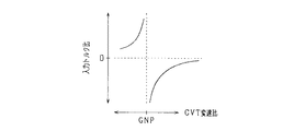
図3に、CVT22の変速比がGNPからずれた場合にエンジン20の出力トルクに対するCVT22に加わるトルクの比(入力トルク比)の関係を示す。図示されるように、CVT22の変速比がGNPからずれることで、入力トルク比が増大する。
FIG. 3 shows the relationship of the ratio of torque applied to CVT 22 (input torque ratio) to the output torque of
そこで本実施形態では、ギアードニュートラル状態への制御を図4に示す処理によって実現する。 Therefore, in this embodiment, control to the geared neutral state is realized by the processing shown in FIG.
図4は、本実施形態にかかるギアードニュートラル制御の処理手順を示す。この処理は、制御装置28によって、たとえば所定周期でくり返し実行される。
FIG. 4 shows a processing procedure of geared neutral control according to the present embodiment. This process is repeatedly executed by the
この一連の処理では、まずステップS10において、シフトレンジがNレンジまたはPレンジから、Dレンジに切り替えられたか否かを判断する。これは、車両の発進を予測する処理である。すなわち、車両の停車状態から車両の発進可能状態への切替操作がなされる場合、これはユーザが車両を発進させるためであると考えられるため、車両が発進すると予測することができる。そして、車両が発進すると予測される場合、ステップS12において、車両の発進を準備する。すなわち、循環用クラッチ24を締結状態に切り替え、エンジン20を起動するとともに、CVT22の変速比を制御装置28によって認識されているGNPに操作する。
In this series of processing, first, in step S10, it is determined whether or not the shift range has been switched from the N range or the P range to the D range. This is a process for predicting the start of the vehicle. That is, when the switching operation from the stop state of the vehicle to the startable state of the vehicle is performed, it is considered that this is for the user to start the vehicle, and therefore it can be predicted that the vehicle starts. If the vehicle is predicted to start, in step S12, the vehicle is prepared to start. That is, the
この際、循環用クラッチ24の締結力は、車両走行時と比較して小さい値に制限する(締結力制限処理)。これは、CVT22の変速比が真のGNPからずれることでCVT22に大きいトルクが加わる場合に、循環用クラッチ24の入力側と出力側とを滑らせることを狙ったものである。これは、第1に、CVT22の変速比が真のGNPからずれる状況下、これを滑りによって検出するための設定である。第2に、CVT22に過度に大きい力が加わることを回避するための設定である。なお、このステップS12の処理は、締結制限手段を構成する。
At this time, the fastening force of the
続くステップS14においては、ブレーキ制御がなされていることと、循環用クラッチ24の入力側および出力側間の回転速度の差の絶対値(|Nc1−Nc2|)が規定値Δ以上であることとの論理積が真であるか否かを判断する。この処理は、CVT22の変速比がGNPからずれることで、駆動輪14に加わるトルクが規定トルクを上回るか否かを判断するものである。この処理は、判断手段を構成する。ここで、規定トルクは、CVT22に信頼性の低下を招くトルクが加わる際の下限トルク未満に設定される。
In the following step S14, the brake control is performed, and the absolute value (| Nc1-Nc2 |) of the difference in rotational speed between the input side and the output side of the
ステップS14において肯定判断される場合、ステップS16において、フラグFを「1」とし、駆動輪14に加わるトルクを制限する処理として、次の処理を行なう。すなわち、エンジン20から駆動輪14までのトータルの変速比(エンジン20の回転速度/駆動輪14の回転速度)の絶対値を増大させるようにCVT22の変速比を操作する。これにより、駆動輪14を回転させようとする方向とは逆方向に駆動輪14を回転させる側にCVT22が操作される。これは、CVT22の変速比を真のGNPにフィードバック制御する処理である。なぜなら、CVT22の変速比がGNPからずれている場合、真のGNPとした場合と比較してトータルの変速比が小さくなるからである。この処理は、フィードバック制御手段を構成する。ちなみに、駆動輪14を回転させようとする方向は、循環用クラッチ24の入力側に対する出力側の相対回転速度に応じて把握すればよい。
When an affirmative determination is made in step S14, the following processing is performed as processing for setting the flag F to “1” and limiting the torque applied to the
またこの際、エアコン用クラッチ32を締結状態とすることで、エンジン20の動力のうち、車載補機に入力される割合を増大させる処理を行なう。これにより、エンジン20の動力のうち駆動輪14へと出力される動力が減少することから、CVT22に加わるトルクを減少させることができる。これは、上記フィードバック制御によって、キャリアの回転方向が頻繁に反転するハンチング現象が生じることを抑制する効果を有する。なお、この処理は、増大手段を構成する。
At this time, by setting the air conditioner clutch 32 to the engaged state, a process of increasing the ratio of the power of the
上記ステップS16の処理は、ステップS14において否定判断されるまで実行される。そして、ステップS14において否定判断される場合、ステップS18において、フラグFが「1」であるか否かを判断する。この処理は、上記ステップS16の処理がなされた状態からなされなくなる状態に移行したタイミングであるか否かを判断するためのものである。 The process of step S16 is executed until a negative determination is made in step S14. If a negative determination is made in step S14, it is determined in step S18 whether or not the flag F is “1”. This process is for determining whether or not it is the timing when the process has shifted from the state in which the process in step S16 is performed to a state in which the process is not performed.
そしてステップS18において肯定判断される場合、ステップS20において、制御装置28の認識するGNPを、そのときのCVT22の変速比に更新する。すなわち、ステップS14において肯定判断される場合、制御装置28の認識するGNPは、真のGNPからずれていることとなる。これに対し、ステップS16の処理の結果、ステップS14において否定判断されるようになった場合、そのときのCVT22の変速比は、それまで認識されていたGNPと比較して真のGNPにより近い値となっていると考えられる。このため、制御装置28の認識するGNPを更新することで、GNPを学習することができる。この処理は、学習手段を構成する。
If an affirmative determination is made in step S18, the GNP recognized by the
また、ステップS20においては、エアコン用クラッチ32を解除するとともに、フラグFを「0」とする。なお、ステップS20の処理が完了する場合や、ステップS10において否定判断される場合には、ステップS22において、締結制限処理を解除する。そして、ステップS22の処理が完了する場合や、ステップS10において否定判断される場合には、この一連の処理を一旦終了する。
In step S20, the
以下、本実施形態の効果のいくつかを記載する。 Hereinafter, some of the effects of this embodiment will be described.
(1)ギアードニュートラル状態への制御時において、循環用クラッチ24の締結力を制限することで、入力側と出力側との滑りに基づき、駆動輪14に加わるトルクが規定トルクを上回るか否かを判断することができる。
(1) Whether or not the torque applied to the
(2)ギアードニュートラル状態への制御時において、循環用クラッチ24の締結力を制限することで、CVT22の変速比が真のGNPからずれることに起因して、駆動輪14に過大なトルクが加わる事態を回避することができる。
(2) At the time of control to the geared neutral state, by restricting the fastening force of the
(3)駆動輪14に加わるトルクが規定トルクを上回ると判断される場合、トータル変速比を増大させることで、CVT22の変速比が真のGNPからずれることに起因して、駆動輪14に過大なトルクが加わる事態を回避することができる。
(3) When it is determined that the torque applied to the
(4)トータル変速比を増大させるに際し、エアコン用クラッチ32を強制的に締結状態とした。これにより、CVT22に加わるトルクを低減することができ、また、GNPへのフィードバック制御に際してハンチングを抑制することができる。
(4) When increasing the total gear ratio, the air-
(5)トータル変速比の増大制御によって駆動輪14に加わるトルクが低減する場合、そのときのCVT22の変速比によって、制御装置28の認識するGNPを更新した。これにより、次回以降のギアードニュートラル制御の制御性を向上させることができる。
<第2の実施形態>
以下、第2の実施形態について、先の第1の実施形態との相違点を中心に図面を参照しつつ説明する。
(5) When the torque applied to the
<Second Embodiment>
Hereinafter, the second embodiment will be described with reference to the drawings with a focus on differences from the first embodiment.
図5は、本実施形態にかかるギアードニュートラル制御の処理手順を示す。この処理は、制御装置28によって、たとえば所定周期でくり返し実行される。なお、図5において、先の図4に示した処理に対応するものについては、便宜上、同一のステップ番号を付している。
FIG. 5 shows a processing procedure of geared neutral control according to the present embodiment. This process is repeatedly executed by the
この一連の処理では、ステップS14において肯定判断される場合、ステップS16aにおいて、駆動輪14に加わるトルクを低減する処理として、ブレーキアクチュエータの操作によって、ブレーキ圧を低減する処理を行なう。すなわち、これにより、駆動輪14が僅かに加速することで、駆動輪14に加わるトルクを低減する。なお、この処理は、低減手段を構成する。また、この処理は、ステップS14において否定判断された後、ステップS18の処理を経て、ステップS20aの処理に移行することで解除される。
<第3の実施形態>
以下、第3の実施形態について、先の第1の実施形態との相違点を中心に図面を参照しつつ説明する。
In this series of processes, when an affirmative determination is made in step S14, in step S16a, a process of reducing the brake pressure is performed by operating the brake actuator as a process of reducing the torque applied to the
<Third Embodiment>
Hereinafter, the third embodiment will be described with reference to the drawings with a focus on differences from the first embodiment.
図6は、本実施形態にかかるギアードニュートラル制御の処理手順を示す。この処理は、制御装置28によって、たとえば所定周期でくり返し実行される。なお、図6において、先の図4に示した処理に対応するものについては、便宜上、同一のステップ番号を付している。
FIG. 6 shows a processing procedure of geared neutral control according to the present embodiment. This process is repeatedly executed by the
この一連の処理では、ステップS14において肯定判断される場合、ステップS16bにおいて、駆動輪14に加わるトルクを低減する処理として、CVT22のベルトを緩める処理を行なう。これは、CVT22のプーリがベルトを押し付ける力を低減することで実現することができる。これにより、CVT22に加わるトルクを軽減することができる。なお、この処理は、緩め制御手段を構成する。また、この処理は、ステップS14において否定判断された後、ステップS18の処理を経て、ステップS20bの処理に移行することで解除される。
<第4の実施形態>
以下、第4の実施形態について、先の第1の実施形態との相違点を中心に図面を参照しつつ説明する。
In this series of processes, when an affirmative determination is made in step S14, a process of loosening the belt of the
<Fourth Embodiment>
Hereinafter, the fourth embodiment will be described with reference to the drawings with a focus on differences from the first embodiment.
図7に、本実施形態にかかるシステム構成を示す。なお、図7において、先の図1に示した部材に対応するものについては、便宜上同一の符号を付している。 FIG. 7 shows a system configuration according to the present embodiment. In FIG. 7, components corresponding to those shown in FIG. 1 are given the same reference numerals for convenience.
図示されるように、本実施形態では、エンジン20をトルクコンバータ40を介してサンギアSに機械的に連結する。トルクコンバータ40は、入力側の回転を作動流体を介して出力側に伝達するものである。ただし、入力側と出力側とを機械的に連結するロックアップクラッチを備えるものを想定している。このロックアップクラッチは、制御装置28によって電気的に操作される。
As illustrated, in the present embodiment, the
こうした構成によれば、ギアードニュートラル制御時においては、トルクコンバータ40のロックアップクラッチを解除しておくことで、CVT22に過度に大きいトルクが加わる事態を回避することができる。これは、CVT22の変速比が真のGNPからずれる場合、エンジン20側とサンギアS側との滑りが大きくなるためである。
According to such a configuration, it is possible to avoid a situation in which excessively large torque is applied to the
なお、トルクコンバータ40は、エンジン20の動力を熱エネルギに変換する変換機構を構成する。
<第5の実施形態>
以下、第5の実施形態について、先の第1の実施形態との相違点を中心に図面を参照しつつ説明する。
The
<Fifth Embodiment>
Hereinafter, a fifth embodiment will be described with reference to the drawings, focusing on differences from the first embodiment.
図8に、本実施形態にかかるシステム構成を示す。なお、図8において、先の図1に示した部材に対応するものについては、便宜上同一の符号を付している。 FIG. 8 shows a system configuration according to the present embodiment. In FIG. 8, components corresponding to those shown in FIG. 1 are given the same reference numerals for convenience.
図示されるように、本実施形態では、キャリアCとデフギア12との間に、ダンパ42を備える。これにより、CVT22に過度に大きいトルクが加わる事態を回避することができる。これは、CVT22の変速比が真のGNPからずれる場合、キャリアCの回転がデフギア12に直接伝えられる代わりに、ダンパ42で吸収されるからである。ダンパ42は、エンジン20の動力を熱エネルギに変換する変換機構を構成する。
As illustrated, in the present embodiment, a
なお、本実施形態では、ギアードニュートラル制御時においてCVT22を保護する対策として、先の図4のステップS16の処理を併せ行なうことが望ましい。これは、ダンパ42によるトルクの吸収は短時間に限って可能であるためである。
<第6の実施形態>
以下、第6の実施形態について、先の第1の実施形態との相違点を中心に図面を参照しつつ説明する。
In the present embodiment, it is desirable to perform the process of step S16 in FIG. 4 as a countermeasure for protecting
<Sixth Embodiment>
Hereinafter, the sixth embodiment will be described with reference to the drawings with a focus on differences from the first embodiment.
図9に、本実施形態にかかるシステム構成を示す。なお、図9において、先の図1に示した部材に対応するものについては、便宜上同一の符号を付している。 FIG. 9 shows a system configuration according to the present embodiment. In FIG. 9, components corresponding to those shown in FIG. 1 are given the same reference numerals for convenience.
図示されるように、本実施形態では、キャリアCとデフギア12との間に、空気溜まり50を備える。空気溜まり50は、内部にキャリアCと一体的に回転する軸に連結されたフィン52を備える。これにより、CVT22に過度に大きいトルクが加わる事態を回避することができる。これは、CVT22の変速比が真のGNPからずれる場合、空気溜まり50がキャリアCのトルクを吸収するからである。空気溜まり50は、エンジン20の動力を熱エネルギに変換する変換機構を構成する。もっとも、空気溜まり50を変換機構として利用するためには、駆動輪14の回転を許容するようにブレーキ力を弱める等することが望ましい。
<その他の実施形態>
なお、上記各実施形態は、以下のように変更して実施してもよい。
As illustrated, in the present embodiment, an
<Other embodiments>
Each of the above embodiments may be modified as follows.
「判断手段について」
たとえば、ベルトの滑りを検出することで、駆動輪14に加わるトルクが規定トルクを上回るか否かを判断する手段であってもよい。また、たとえば、歪ゲージ式トルク検出器を備えてその検出値を利用する手段であってもよい。
About judgment means
For example, it may be a means for determining whether or not the torque applied to the
さらに、遊星歯車機構10とデフギア12との間等には、通常、機械的ながたが存在すため、駆動輪14が静止状態であってもキャリアCの微小回転が可能となっている。このため、これを利用して、キャリアCの回転に基づき、駆動輪14に加わるトルクが規定トルクを上回るか否かを判断してもよい。なお、この手段は、実際に規定トルクを上回る以前に、上回るであろうことを予測判断する手段となる。
Further, since there is usually a mechanical rattle between the
「フィードバック制御手段について」
駆動輪14を回転させようとする方向の把握手法としては、循環用クラッチ24の入力側に対する出力側の相対回転速度の符号の検出結果に基づくものに限らない。たとえば遊星歯車機構10のキャリアCの回転方向の検出結果に基づくものであってもよい。
About feedback control means
The method of grasping the direction in which the
駆動輪14に加わるトルクが規定トルクを上回ると判断されることをトリガとして、駆動輪14の進行しようとする回転方向とは逆向きに回転する側にCVT22の変速比を操作する処理を必ず行なうものに限らない。たとえば、駆動輪14に加わるトルクが規定トルクを上回ると判断される場合、CVT22のプーリの溝巾を固定する力を低減し(緩め制御手段による処理)、それによっても規定トルクを上回る状態が解消されない場合に限ってトータル変速比の絶対値を増大させるものであってもよい。
Triggered by the fact that the torque applied to the
また、増大手段(図4;ステップS16)、低減手段(図5;ステップS16a)、緩め制御手段(図6;ステップS16b)による処理を併せ行なうものに限らない。たとえば増大手段を備えなくても、締結制限手段による締結力制限処理を行なうなら、ハンチング抑制の効果を奏する。 Further, the processing is not limited to the processing by the increasing means (FIG. 4; step S16), the reducing means (FIG. 5; step S16a), and the loosening control means (FIG. 6; step S16b). For example, even if the increasing means is not provided, if the fastening force limiting process is performed by the fastening limiting means, the effect of suppressing hunting is obtained.
ハンチング対策としては、他にも、フィードバックゲインを低減することで対処してもよい。加えて、トータル変速比の符号が正である領域において絶対値を増大させる側にCVT22の変速比を変更する処理と、負である領域において絶対値を増大させる側にCVT22の変速比を変更する処理との一対の処理について、それらの切り替えにヒステリシスを持たせる設定としたりすることで対処してもよい。
As another countermeasure against hunting, the feedback gain may be reduced. In addition, the process of changing the transmission ratio of the
「学習手段について」
上記各実施形態では、フラグFが1であるときにステップS14において否定判断される都度、ギアードニュートラルポイントGNPの学習値を変更したがこれに限らない。たとえば、ブレーキが解除されることでステップS14において否定判断される場合には、学習を禁止してもよい。
"About learning means"
In each of the above embodiments, every time a negative determination is made in step S14 when the flag F is 1, the learned value of the geared neutral point GNP is changed, but this is not limitative. For example, when a negative determination is made in step S14 by releasing the brake, learning may be prohibited.
「締結制限手段について」
判断手段が締結制限手段を利用しないなら、これを設けなくてもよい。もっとも、判断手段が締結制限手段を利用しない場合であっても、締結制限手段を備えるなら、ドライブレンジに切り替えられた際にCVT22の変速比が真のGNPからずれていたとしても、CVT22に過大なトルクが加わる事態を好適に回避することはできる。
About fastening restriction means
If the judging means does not use the fastening limiting means, this need not be provided. However, even if the judging means does not use the fastening limiting means, if the fastening limiting means is provided, even if the gear ratio of the
「増大手段について」
駆動源(エンジン20)の動力を吸収する負荷としては、コンプレッサ30に限らない。たとえば、ウォータポンプ等であってもよい。
"About means of increase"
The load that absorbs the power of the drive source (engine 20) is not limited to the
「変換機構について」
先の第4の実施形態(図7)において、トルクコンバータ40を、リングギアRとギア26との間や、キャリアCとデフギア12との間に設けてもよい。
About the conversion mechanism
In the fourth embodiment (FIG. 7), the
先の第5の実施形態において、ダンパ42を、リングギアRとギア26との間や、エンジン20とサンギアSとの間に設けてもよい。
In the previous fifth embodiment, the
上記各実施形態で例示したものに限らず、たとえばトルクリミッタを備えるようにしてもよい。 For example, a torque limiter may be provided without being limited to those exemplified in the above embodiments.
「制限手段について」
たとえば、駆動輪14に加わるトルクが規定トルクを上回ると判断される場合、駆動源(エンジン20)の動力を低減する処理を行なうものであってもよい。
"Restriction means"
For example, when it is determined that the torque applied to the
「共線図上において回転速度が1直線上に並ぶ3つの回転体について」
駆動輪14に機械的に連結される回転体(第3の回転体)がキャリアCであるものに限らない。たとえば、リングギアRに駆動輪14を機械的に連結し、キャリアCとサンギアSとをCVT22を介して機械的に連結してもよい。
"About three rotating bodies whose rotational speeds are aligned on a straight line on the nomograph"
The rotating body (third rotating body) mechanically coupled to the
また、3つの回転体としては、遊星歯車機構を構成するものに限らず、たとえばデフギアを構成するものであってもよい。 Further, the three rotating bodies are not limited to those constituting a planetary gear mechanism, and may be those constituting, for example, a differential gear.
「駆動源について」
エンジン20に限らない。たとえばモータジェネレータであってもよい。また、エンジンとモータジェネレータとの双方を備えるものであってもよい。この場合、たとえば、先の図1において、モータジェネレータについては、CVT22とリングギアRとの間に機械的に連結してもよい。
"About drive sources"
The
10…遊星歯車機構、14…駆動輪、20…エンジン、22…CVT、28…制御装置。
DESCRIPTION OF
Claims (9)
ギアードニュートラル状態を実現すべく前記操作手段によって前記無段変速装置が操作される状況下、前記駆動源の動力に起因して前記駆動輪に加わるトルクを制限する制限手段(S12,S16,16a,S16b,40,42,50)と、
を備えることを特徴とする動力伝達装置。 In order to realize a geared neutral state in which the rotational speed of the drive wheel (14) is zero under a situation where the rotational speed of the drive source (20) is not zero, the power source of the drive source (20) is provided on a path for transmitting the power to the drive wheel Operating means (S12) for operating the gear ratio of the continuously variable transmission;
Limiting means (S12, S16, 16a, etc.) for limiting the torque applied to the driving wheel due to the power of the driving source under the condition that the continuously variable transmission is operated by the operating means to realize a geared neutral state. S16b, 40, 42, 50),
A power transmission device comprising:
ギアードニュートラル状態を実現すべく前記無段変速装置が操作される状況下、前記駆動源の動力に起因して前記駆動輪に加わるトルクが規定トルクを上回るか否かを判断する判断手段(S14)と、
前記判断手段によって規定トルクを上回ると判断される場合、進行しようとする方向とは逆方向に前記駆動輪が回転する側に前記無段変速装置の変速比を操作するフィードバック制御手段(S16,S16a,S16b)と、
を備えることを特徴とする請求項1記載の動力伝達装置。 The limiting means is
Judgment means for judging whether or not the torque applied to the drive wheels due to the power of the drive source exceeds a specified torque under the condition that the continuously variable transmission is operated to realize a geared neutral state (S14). When,
When it is determined by the determining means that the torque exceeds the specified torque, feedback control means (S16, S16a) for operating the speed ratio of the continuously variable transmission to the side where the drive wheel rotates in the direction opposite to the direction of traveling , S16b),
The power transmission device according to claim 1, further comprising:
前記第3の回転体には駆動輪が機械的に連結されており、
前記第1の回転体および前記第2の回転体は、前記無段変速装置を介して機械的に連結可能とされており、
前記第1の回転体および前記第2の回転体の間には、入力側および出力側の締結および解除を切り替える締結手段(24)が備えられ、
前記制限手段は、ギアードニュートラル状態を実現すべく前記無段変速装置が操作される状況下、前記締結手段による前記入力側および前記出力側を締結させる力を制限する締結制限手段(S12)を備え、
前記判断手段は、前記締結制限手段による締結の制限がなされる状況下、前記入力側および前記出力側間の滑りの検出に基づき、前記規定トルクを上回るか否かを判断することを特徴とする請求項2記載の動力伝達装置。 The path for transmitting the power of the driving source to the driving wheels is a first rotating body (R), a second rotating body (S), which are three rotating bodies whose rotational speeds are aligned on a collinear chart, And a third rotating body (C),
Drive wheels are mechanically coupled to the third rotating body,
The first rotator and the second rotator are mechanically connectable via the continuously variable transmission,
Between the first rotating body and the second rotating body, a fastening means (24) for switching between fastening and release on the input side and the output side is provided,
The restricting means includes a fastening restricting means (S12) for restricting a force for fastening the input side and the output side by the fastening means in a situation where the continuously variable transmission is operated to realize a geared neutral state. ,
The determination means determines whether or not the specified torque is exceeded based on detection of slippage between the input side and the output side in a situation where the fastening restriction is made by the fastening restriction means. The power transmission device according to claim 2.
前記操作手段は、前記学習手段によって学習された変速比に基づき、前記ギアードニュートラル状態を実現すべく前記無段変速装置を操作することを特徴とする請求項2または3記載の動力伝達装置。 The feedback control means includes learning means (S14, S16, S18, S20) for learning a gear ratio that becomes a geared neutral state by an operation of a gear ratio of the continuously variable transmission.
4. The power transmission device according to claim 2, wherein the operating unit operates the continuously variable transmission to realize the geared neutral state based on a gear ratio learned by the learning unit. 5.
前記フィードバック制御手段による前記変速比の制御がなされる状況下、前記駆動源の動力のうち前記車載補機に入力される割合を増大させる増大手段(S16)を備えることを特徴とする請求項2〜5のいずれか1項に記載の動力伝達装置。 An in-vehicle auxiliary machine (30) is mechanically connectable to the drive source,
3. An increasing means (S16) for increasing a ratio of the power of the drive source that is input to the in-vehicle auxiliary device in a situation where the speed ratio is controlled by the feedback control means. The power transmission device according to any one of?
前記制限手段は、
ギアードニュートラル状態を実現すべく前記無段変速装置が操作される状況下、前記駆動源の動力に起因して前記駆動輪に加わるトルクが規定トルクを上回るか否かを判断する判断手段と、
前記判断手段によって規定トルクを上回ると判断される場合、前記無段変速装置のベルトを緩める処理を行なう緩め制御手段(S16b)と、
を備えることを特徴とする請求項1記載の動力伝達装置。 The continuously variable transmission is of a belt type,
The limiting means is
Judgment means for judging whether or not the torque applied to the drive wheel due to the power of the drive source exceeds a specified torque under the situation where the continuously variable transmission is operated to realize a geared neutral state;
A loosening control means (S16b) for performing a process of loosening the belt of the continuously variable transmission when the judgment means judges that the torque exceeds the specified torque;
The power transmission device according to claim 1, further comprising:
前記第1の回転体および前記第2の回転体は、前記無段変速装置を介して機械的に連結可能とされており、
前記第1の回転体および前記第2の回転体の間には、入力側および出力側の締結および解除を切り替える締結手段が備えられ、
前記制限手段は、ギアードニュートラル状態を実現すべく前記無段変速装置が操作される状況下、前記締結手段による前記入力側および前記出力側を締結させる力を制限する締結制限手段を備えることで、前記締結手段を前記変換機構とすることを特徴とする請求項8記載の動力伝達装置。 The path for transmitting the power of the driving source to the driving wheels is a first rotating body, a second rotating body, and a third rotating body, which are three rotating bodies whose rotational speeds are aligned on a collinear diagram. With
The first rotator and the second rotator are mechanically connectable via the continuously variable transmission,
Between the first rotating body and the second rotating body, a fastening means for switching between fastening and releasing on the input side and the output side is provided,
The limiting means includes a fastening limiting means for limiting a force for fastening the input side and the output side by the fastening means in a situation where the continuously variable transmission is operated to realize a geared neutral state. The power transmission device according to claim 8, wherein the fastening means is the conversion mechanism.
Priority Applications (1)
| Application Number | Priority Date | Filing Date | Title |
|---|---|---|---|
| JP2012056594A JP2013190027A (en) | 2012-03-14 | 2012-03-14 | Power transmission device |
Applications Claiming Priority (1)
| Application Number | Priority Date | Filing Date | Title |
|---|---|---|---|
| JP2012056594A JP2013190027A (en) | 2012-03-14 | 2012-03-14 | Power transmission device |
Publications (1)
| Publication Number | Publication Date |
|---|---|
| JP2013190027A true JP2013190027A (en) | 2013-09-26 |
Family
ID=49390503
Family Applications (1)
| Application Number | Title | Priority Date | Filing Date |
|---|---|---|---|
| JP2012056594A Pending JP2013190027A (en) | 2012-03-14 | 2012-03-14 | Power transmission device |
Country Status (1)
| Country | Link |
|---|---|
| JP (1) | JP2013190027A (en) |
Citations (5)
| Publication number | Priority date | Publication date | Assignee | Title |
|---|---|---|---|---|
| JPH10141101A (en) * | 1996-11-06 | 1998-05-26 | Aisin Aw Co Ltd | Continuously variable transmission |
| JP2002039320A (en) * | 2000-07-28 | 2002-02-06 | Nissan Motor Co Ltd | Torque limiting mechanism of infinitely variable transmission |
| JP2002168328A (en) * | 2000-12-01 | 2002-06-14 | Nissan Motor Co Ltd | Control device for infinitely variable transmission |
| US20110118077A1 (en) * | 2009-11-16 | 2011-05-19 | Nippon Soken, Inc. | Vehicle power transmission device and control system for power transmission |
| JP2012002330A (en) * | 2010-06-21 | 2012-01-05 | Nsk Ltd | Continuously variable transmission apparatus |
-
2012
- 2012-03-14 JP JP2012056594A patent/JP2013190027A/en active Pending
Patent Citations (5)
| Publication number | Priority date | Publication date | Assignee | Title |
|---|---|---|---|---|
| JPH10141101A (en) * | 1996-11-06 | 1998-05-26 | Aisin Aw Co Ltd | Continuously variable transmission |
| JP2002039320A (en) * | 2000-07-28 | 2002-02-06 | Nissan Motor Co Ltd | Torque limiting mechanism of infinitely variable transmission |
| JP2002168328A (en) * | 2000-12-01 | 2002-06-14 | Nissan Motor Co Ltd | Control device for infinitely variable transmission |
| US20110118077A1 (en) * | 2009-11-16 | 2011-05-19 | Nippon Soken, Inc. | Vehicle power transmission device and control system for power transmission |
| JP2012002330A (en) * | 2010-06-21 | 2012-01-05 | Nsk Ltd | Continuously variable transmission apparatus |
Similar Documents
| Publication | Publication Date | Title |
|---|---|---|
| JP4131253B2 (en) | Vehicle starting friction element control device | |
| JP4411827B2 (en) | Power transmission device for hybrid vehicle | |
| US9599203B2 (en) | Continuously variable transmission for vehicle | |
| JP6015852B2 (en) | Vehicle control apparatus and method | |
| JP6911711B2 (en) | Control device for vehicle power transmission device | |
| JP6209672B2 (en) | Vehicle control apparatus and control method thereof | |
| JP2012126318A5 (en) | ||
| JP2005291111A (en) | Input torque control device for belt type continuously variable transmission for vehicle | |
| WO2016013238A1 (en) | Hybrid vehicle control device and control method therefor | |
| JP6191492B2 (en) | Vehicle drive device | |
| WO2017169396A1 (en) | Control device | |
| US20150166054A1 (en) | Power transmission unit | |
| JPH11189052A (en) | Hybrid vehicle | |
| JP5341998B2 (en) | Vehicle control device | |
| JP2009227268A (en) | Vehicular drive apparatus | |
| JP5310050B2 (en) | Vehicle drive device | |
| JP2013190027A (en) | Power transmission device | |
| JP2013221590A (en) | Control device for vehicle | |
| JP4604568B2 (en) | Vehicle starting friction element control device | |
| JP2005155508A (en) | Automobile, its control device, and its driving force transmission device | |
| JP2016061348A (en) | Control device for continuously variable transmission | |
| JP6660217B2 (en) | Vehicle control device | |
| JP2001329880A (en) | Vehicle drive | |
| JP5230874B2 (en) | In-vehicle power transmission device | |
| JP5236709B2 (en) | In-vehicle power transmission device |
Legal Events
| Date | Code | Title | Description |
|---|---|---|---|
| A621 | Written request for application examination |
Free format text: JAPANESE INTERMEDIATE CODE: A621 Effective date: 20140515 |
|
| A131 | Notification of reasons for refusal |
Free format text: JAPANESE INTERMEDIATE CODE: A131 Effective date: 20150224 |
|
| A977 | Report on retrieval |
Free format text: JAPANESE INTERMEDIATE CODE: A971007 Effective date: 20150227 |
|
| A02 | Decision of refusal |
Free format text: JAPANESE INTERMEDIATE CODE: A02 Effective date: 20150630 |