JP2013122494A - Focus detector and camera - Google Patents
Focus detector and camera Download PDFInfo
- Publication number
- JP2013122494A JP2013122494A JP2011270162A JP2011270162A JP2013122494A JP 2013122494 A JP2013122494 A JP 2013122494A JP 2011270162 A JP2011270162 A JP 2011270162A JP 2011270162 A JP2011270162 A JP 2011270162A JP 2013122494 A JP2013122494 A JP 2013122494A
- Authority
- JP
- Japan
- Prior art keywords
- focus detection
- focus
- optical system
- image sensor
- phase difference
- Prior art date
- Legal status (The legal status is an assumption and is not a legal conclusion. Google has not performed a legal analysis and makes no representation as to the accuracy of the status listed.)
- Pending
Links
Images




Landscapes
- Automatic Focus Adjustment (AREA)
- Transforming Light Signals Into Electric Signals (AREA)
- Studio Devices (AREA)
- Focusing (AREA)
Abstract
【課題】焦点検出点の数を適切に増やすこと。
【解決手段】焦点検出装置は、焦点検出用の画素列を含む撮像兼焦点検出用撮像素子212を有し、該撮像素子212が撮影光学系210を通して撮像した出力信号であって焦点検出用の画素列からの信号を用いて一対の像の位相差情報を演算し、該位相差情報に基づいて撮影光学系による焦点調節状態を検出する第1の焦点検出手段108と、第1の焦点検出手段108とは別に設けられており、撮影光学系の異なる領域を通過した一対の焦点検出用光束によって得られる一対の像の位相差情報に基づいて、撮影光学系による焦点調節状態を検出する第2の焦点検出手段109と、を有し、第2の焦点検出手段109は、撮影画面内の所定領域に対応する一対の焦点検出用光束に基づく位相差情報を取得し、第1の焦点検出手段108は、撮影画面内の所定領域とは異なる領域に対応する位置に存在する、撮像素子212上の焦点検出用の画素列からの信号を用いて位相差情報を演算することを特徴とする。
【選択図】図4To appropriately increase the number of focus detection points.
A focus detection apparatus includes an image pickup and focus detection image pickup element 212 including a pixel row for focus detection, and is an output signal imaged by the image pickup element 212 through a photographing optical system 210 for focus detection. First focus detection means 108 that calculates phase difference information of a pair of images using a signal from the pixel array and detects a focus adjustment state by the photographing optical system based on the phase difference information, and first focus detection The first means is provided separately from the means 108 and detects a focus adjustment state by the photographing optical system based on phase difference information of a pair of images obtained by a pair of focus detection light beams that have passed through different regions of the photographing optical system. Two focus detection means 109, and the second focus detection means 109 acquires phase difference information based on a pair of focus detection light beams corresponding to a predetermined area in the imaging screen, and performs first focus detection. The means 108 is Located at a position corresponding to an area different from the predetermined area of the shadow in the screen, characterized by calculating the phase difference information by using the signals from the pixel rows for focus detection on the image sensor 212.
[Selection] Figure 4
Description
本発明は、焦点検出装置およびカメラに関する。 The present invention relates to a focus detection apparatus and a camera.
焦点検出用の複数の画素(画素列)を有する撮像兼焦点検出用撮像素子が撮影光学系を通して撮像した出力信号のうち、焦点検出用画素列からの信号を用いて演算した一対の像の位相差(いわゆる像ズレ)に基づいて、上記撮影光学系による焦点調節状態を検出する第1の焦点検出装置と、第1の焦点検出装置と別に、上記撮影光学系の異なる領域を通過した一対の焦点検出用光束によって得られる一対の像の位相差に基づいて、上記撮影光学系による焦点調節状態を検出する第2の焦点検出装置と、を備えるカメラが知られている(特許文献1参照)。 The position of a pair of images calculated using the signal from the focus detection pixel column among the output signals imaged by the imaging / focus detection image sensor having a plurality of focus detection pixels (pixel columns) through the photographing optical system. Separately from the first focus detection device for detecting the focus adjustment state by the photographing optical system based on the phase difference (so-called image shift) and the first focus detection device, a pair of passes through different regions of the photographing optical system There is known a camera including a second focus detection device that detects a focus adjustment state by the photographing optical system based on a phase difference between a pair of images obtained by a focus detection light beam (see Patent Document 1). .
撮影画面内のより多くの位置で焦点検出を行いたい場合、焦点検出位置を単純に増やすだけでは以下の問題が生じてしまう。すなわち、第1の焦点検出装置において撮影画面内に多数の焦点検出点を設けると、撮影画像を得るための補間処理が増えてしまう。一方、第2の焦点検出装置において撮影画面内に多数の焦点検出点を設けると、装置の大型化を招いてしまう。 When it is desired to perform focus detection at a larger number of positions in the shooting screen, simply increasing the focus detection position causes the following problems. That is, if a large number of focus detection points are provided in the shooting screen in the first focus detection device, interpolation processing for obtaining a shot image increases. On the other hand, if a large number of focus detection points are provided in the shooting screen in the second focus detection device, the size of the device is increased.
(1)本発明による焦点検出装置は、焦点検出用の画素列を含む撮像兼焦点検出用撮像素子を有し、該撮像素子が撮影光学系を通して撮像した出力信号であって焦点検出用の画素列からの信号を用いて一対の像の位相差情報を演算し、該位相差情報に基づいて撮影光学系による焦点調節状態を検出する第1の焦点検出手段と、第1の焦点検出手段とは別に設けられており、撮影光学系の異なる領域を通過した一対の焦点検出用光束によって得られる一対の像の位相差情報に基づいて、撮影光学系による焦点調節状態を検出する第2の焦点検出手段と、を有し、第2の焦点検出手段は、撮影画面内の所定領域に対応する一対の焦点検出用光束に基づく位相差情報を取得し、第1の焦点検出手段は、撮影画面内の所定領域とは異なる領域に対応する位置に存在する、撮像素子上の焦点検出用の画素列からの信号を用いて位相差情報を演算することを特徴とする。
(2)請求項9に記載の発明によるカメラは、請求項1〜5のいずれか一項に記載の焦点検出装置と、入射された光束を折り曲げる光学部材と、撮影光学系を通過した光束の光路上の第1位置と光路外の第2位置との間で光学部材を移動させる光学部材移動機構と、第1の焦点検出手段が焦点調節状態を検出する場合および撮影時は光学部材を第2位置外へ移動させて光束を第1の焦点検出手段へ導き、第2の焦点検出手段が焦点調節状態を検出する場合は光学部材を第1位置へ移動させて光束を第2の焦点検出手段へ導くように光学部材移動機構を制御する駆動制御手段と、第1の焦点検出手段または第2の焦点検出手段によって検出された焦点調節状態に基づいて、撮影光学系を合焦させるための光学系駆動信号を発する合焦制御手段と、を備えることを特徴とする。
(3)請求項11に記載の発明によるカメラは、請求項1〜5のいずれか一項に記載の焦点検出装置と、入射された光束を折り曲げるとともに透過させる半透過性の光学部材と、撮影光学系を通過した光束の光路上の第1位置と光路外の第2位置との間で光学部材を移動させる光学部材移動機構と、第1の焦点検出手段および第2の焦点検出手段の少なくとも一方が焦点調節状態を検出する場合は光学部材を第1位置へ移動させて光束を第1の焦点検出手段および第2の焦点検出手段の双方へ導き、撮影時は光学部材を第2位置へ移動させて光束を第1の焦点検出手段のみへ導くように光学部材移動機構を制御する駆動制御手段と、第1の焦点検出手段または第2の焦点検出手段によって検出された焦点調節状態に基づいて、撮影光学系を合焦させるための光学系駆動信号を発する合焦制御手段と、を備えることを特徴とする。
(1) A focus detection apparatus according to the present invention has an imaging and focus detection imaging element including a focus detection pixel array, and is an output signal captured by the imaging element through a photographing optical system, and the focus detection pixel. A first focus detection unit that calculates phase difference information of a pair of images using a signal from the column and detects a focus adjustment state by the photographing optical system based on the phase difference information; and a first focus detection unit; And a second focus that detects a focus adjustment state by the imaging optical system based on phase difference information of a pair of images obtained by a pair of focus detection light beams that have passed through different regions of the imaging optical system. And a second focus detection unit acquires phase difference information based on a pair of focus detection light beams corresponding to a predetermined area in the shooting screen, and the first focus detection unit It corresponds to the area different from the predetermined area in Present in position, and calculates the phase difference information by using the signals from the pixel rows for focus detection on the image pickup device.
(2) A camera according to a ninth aspect of the invention is a camera according to any one of the first to fifth aspects, an optical member that bends an incident light beam, and a light beam that has passed through a photographing optical system. An optical member moving mechanism for moving the optical member between a first position on the optical path and a second position outside the optical path, and the first optical focus detection unit detecting the focus adjustment state and the optical member in the first position when photographing. When the second focus detection means detects the focus adjustment state, the optical member is moved to the first position to detect the light beam as the second focus. A driving control unit that controls the optical member moving mechanism so as to lead to the unit, and a focusing optical system that focuses on the focus adjustment state detected by the first focus detection unit or the second focus detection unit. Focusing control means for emitting an optical system driving signal; Characterized in that it comprises a.
(3) A camera according to an eleventh aspect of the invention includes a focus detection apparatus according to any one of the first to fifth aspects, a semi-transmissive optical member that bends and transmits an incident light beam, and photographing. An optical member moving mechanism that moves the optical member between a first position on the optical path of the light beam that has passed through the optical system and a second position outside the optical path; and at least one of the first focus detection means and the second focus detection means When one detects the focus adjustment state, the optical member is moved to the first position to guide the light beam to both the first focus detection means and the second focus detection means, and at the time of photographing, the optical member is moved to the second position. Based on the drive control means for controlling the optical member moving mechanism so as to move the light beam only to the first focus detection means and the focus adjustment state detected by the first focus detection means or the second focus detection means. The shooting optical system. And focus control means for emitting optical system driving signal for, characterized in that it comprises a.
本発明によれば、位相差方式の焦点検出装置の焦点検出点を適切に増やすことができる。 ADVANTAGE OF THE INVENTION According to this invention, the focus detection point of the phase difference type focus detection apparatus can be increased appropriately.
以下、図面を参照して本発明を実施するための形態について説明する。
(第一の実施形態)
図1および図2は、本発明の第一の実施形態による焦点検出装置を搭載した一眼レフ電子カメラの要部構成を説明する図である。図1および図2において、カメラ本体201に対して着脱可能に構成される撮影レンズ鏡筒202が装着されている。
Hereinafter, embodiments for carrying out the present invention will be described with reference to the drawings.
(First embodiment)
FIG. 1 and FIG. 2 are diagrams for explaining the main configuration of a single-lens reflex electronic camera equipped with a focus detection device according to a first embodiment of the present invention. 1 and 2, a
被写体からの光は、撮影レンズ鏡筒202の撮影光学系210および絞り211を介してカメラ本体201へ入射される。カメラ本体201に入射した被写体光は、レリーズ前は図1に例示したミラーダウン状態にある半透過のクイックリターンミラー(以下メインミラーと呼ぶ)203で上方のファインダー部へ向けて折り曲げられ、拡散スクリーン206に結像する。また、メインミラー203を透過した被写体光の一部はサブミラー204で下方へ反射され、焦点検出用光束として専用AF(オートフォーカス)素子207へ入射される。専用AF素子207は、撮影光学系210による焦点調節状態を検出する焦点検出処理(公知の瞳分割方式のAF処理)において用いられるものである。
Light from the subject enters the
拡散スクリーン206に結像した被写体光はさらに、ペンタプリズム208へ入射される。ペンタプリズム208は、入射された被写体光を接眼光学系209へ導く。撮影者は、ファインダー接眼窓41(図3)から接眼光学系209を通してファインダーによる被写体像を観察する。
The subject light imaged on the diffusing
レリーズ後は、図2に例示したミラーアップ位置へメインミラー203が回動し、被写体光はメカニカルシャッター205を介して撮像素子212へ導かれ、その撮像面上に被写体像を結像する。撮像素子212は、画素に対応する複数の光電変換素子を備えたCMOSイメージセンサなどによって構成される。撮像素子212は、撮像面上に結像されている被写体像を撮像し、被写体像の明るさに応じた光電変換信号を出力する。なお、撮像素子212の撮像面側に光学ローパスフィルター213が設けられている。
After the release, the
レンズ駆動機構214は、撮影光学系210を構成するフォーカス調節レンズを光軸方向に進退駆動する。フォーカス調節レンズの駆動方向および駆動量は、カメラ本体201側から指示される。なお、図を簡単にするため、撮影光学系210を単レンズとして表している。
The
図1のミラーダウン状態は、撮影者が接眼光学系209を介して被写体像を観察できるようにする撮影準備状態である。この状態で焦点検出を行う場合、電子カメラは専用AF素子207を用いて焦点検出を行う(専用素子AFと呼ぶ)。
The mirror-down state in FIG. 1 is a shooting preparation state in which the photographer can observe the subject image via the eyepiece
図2のミラーアップ状態は、撮影時と同様に被写体光が全て撮像素子212へ導かれる。この状態で焦点検出を行う場合、電子カメラは撮像素子212からの出力信号に基づいて焦点検出を行う(撮像素子AFと呼ぶ)。
In the mirror-up state of FIG. 2, all the subject light is guided to the
図3は、電子カメラの外観を例示する図である。図3において、電子カメラの上面に、メインスイッチSW1と、レリーズボタンSW2と、白黒液晶モニター31とを有する。電子カメラの背面に、左選択スイッチSW6と、右選択スイッチSW7と、上選択スイッチSW8と、下選択スイッチSW9と、確定スイッチSW10と、コマンドダイアル45と、切替レバー51と、カラー液晶モニター61と、ファインダー接眼窓41とを有する。
FIG. 3 is a diagram illustrating an appearance of the electronic camera. In FIG. 3, a main switch SW1, a release button SW2, and a monochrome
電子カメラは、専用素子AFを行うか、あるいは撮像素子AFを行うかを切替レバー51の設定状態に応じて決定する。たとえば、切替レバー51が左のポジションに切り替えられている場合、専用素子AFをミラーダウン時に行う。撮影者は、光学ファインダーを通して被写体像を観察しながらフレーミングを行う。
The electronic camera determines whether to perform the dedicated element AF or the image sensor AF according to the setting state of the switching
一方、切替レバー51が右のポジションに切り替えられている場合、電子カメラは、撮像素子AFをミラーアップ時に行う。撮影者は、光学ファインダーではなくカラー液晶モニター61に映し出されるライブビュー画像を観察しながらフレーミングを行う。
On the other hand, when the switching
図4は、上述した電子カメラの構成を説明するブロック図である。電子カメラは、マイクロコンピュータ101によって制御される。メインスイッチSW1は、電子カメラの電源オン/オフをそれぞれ指示する操作信号を出力する。レリーズスイッチ(SW2)は、レリーズボタンSW2の押下操作に連動して撮影開始を指示する信号を出力する。
FIG. 4 is a block diagram illustrating the configuration of the electronic camera described above. The electronic camera is controlled by the
取消しスイッチSW3は、操作取消しを示す操作信号を出力する。モードスイッチSW4は、電子カメラの動作モード、すなわち、撮影モードおよび再生モード等を切替えるための操作信号をそれぞれ出力する。 The cancel switch SW3 outputs an operation signal indicating operation cancellation. The mode switch SW4 outputs an operation signal for switching the operation mode of the electronic camera, that is, the photographing mode and the reproduction mode.
左選択スイッチSW6、右選択スイッチSW7、上選択スイッチSW8、および下選択スイッチSW9は、それぞれ選択方向を示す操作信号を出力する。確定スイッチSW10は、操作確定を示す操作信号を出力する。スイッチSW13およびスイッチSW14は、コマンドダイアル45の回転操作に応じて操作信号を出力する。
The left selection switch SW6, right selection switch SW7, upper selection switch SW8, and lower selection switch SW9 each output an operation signal indicating the selection direction. The confirmation switch SW10 outputs an operation signal indicating operation confirmation. The switch SW13 and the switch SW14 output an operation signal according to the rotation operation of the
レンズ鏡筒202はレンズ鏡筒内CPUを含み、マイクロコンピュータ101との間で通信を行う。レンズ鏡筒内CPUは、マイクロコンピュータ101からの指示に応じてレンズ駆動機構214(図1、図2)を駆動制御し、上記フォーカス調節レンズ(210)を進退移動させる。
The
撮像処理回路107は、撮像素子212から出力される画像データに対して所定の画像処理を行う。画像処理は、γ変換処理やホワイトバランス調整処理などを含む。
The
撮像素子AF回路108は、撮像素子212の所定画素からの出力信号に基づいて像ズレ検出演算処理(相関処理、位相差検出処理)を施すことにより、いわゆる瞳分割型位相差検出方式(マイクロレンズ方式)で一対の像の像ズレ量を検出する。さらに、像ズレ量に所定の変換係数を乗ずることにより、予定焦点面に対する現在の結像面の偏差(デフォーカス量)を算出する。そして、該デフォーカス量に応じて上記フォーカス調節レンズの移動方向および移動量を演算する。像ズレ検出演算処理の詳細については後述する。
The image
専用素子AF回路109は、専用AF素子207からの出力信号に基づいて像ズレ検出演算処理(相関処理、位相差検出処理)を施すことにより、撮影光学系210の異なる領域を通過した一対の焦点検出用光束によって得られる一対の像の像ズレ量を検出する。さらに、像ズレ量に所定の変換係数を乗ずることにより、予定焦点面に対する現在の結像面の偏差(デフォーカス量)を算出する。そして、該デフォーカス量に応じて上記フォーカス調節レンズの移動方向および移動量を演算する。像ズレ検出演算処理の詳細については後述する。
The dedicated
測光装置102は、撮影光学系210を通過した被写体光を受光して測光演算を行う。ドライバ回路103は、マイクロコンピュータ101からの指令に応じてメカニカルシャッター205を駆動する。ドライバ回路104は、マイクロコンピュータ101からの指令に応じて絞り機構214を駆動する。絞り機構214が不図示の絞り駆動レバーを動かすと、レンズ鏡筒202側の絞り211の口径が変化する。ドライバ回路105は、マイクロコンピュータ101からの指令に応じてミラー機構215を駆動する。ミラー機構215は、メインミラー203およびサブミラー204をアップ駆動またはダウン駆動する。
The
外部インタフェース113は、電子カメラ内のデータをパソコンや別の電子カメラなどの外部機器へ出力(送信)したり、外部機器からのデータを入力(受信)したりするインターフェース回路である。外部インタフェース113の例として、RS232C、USB、IEEE1394などがある。
The
表示制御部110は、マイクロコンピュータ101からの指令によりカラー液晶モニター61に対する駆動信号を生成する。カラー液晶モニター61は、画像や操作メニューなどを表示する。表示制御部111は、マイクロコンピュータ101からの指令により白黒液晶モニター31に対する駆動信号を生成する。白黒液晶モニター31は、コマ数や撮影条件などの撮影情報を表示する。
The
メモリカード119は、カードコネクター117を介して電子カメラに着脱される記録媒体である。メモリカード119には画像データや音声データが記録される。ドライバ回路106は、マイクロコンピュータ101からの指令に応じて測距エリア照射装置115を駆動制御する。測距エリア照射装置115は、専用素子AF時および撮像素子AF時における必要な場合に、測距補助光を発して被写体を照明する。
The
画像記憶メモリ121は、上述した画像処理、後述する圧縮処理および伸長処理の際に一時的に画像データを格納する。圧縮/伸長回路123は、たとえば、JPEGなど所定の方式で画像データを圧縮処理したり、圧縮された画像データを伸長処理したりする。メモリ125は、マイクロコンピュータ101の作業領域として利用される。タイマー127は、マイクロコンピュータ101によって指定された時間を計時し、タイムアップ信号を出力する。電池129は、電子カメラ内の各部に電力を供給する。
The
<撮像素子AF処理>
撮像素子AF回路108で行うAF(自動焦点調節)処理について詳細に説明する。本実施形態の撮像素子212は、フォーカス検出用の画素(焦点検出用画素と呼ぶ)を有する。この撮像素子212は、特開2007−279312号公報に記載されている撮像素子と同様のものである。撮像素子AF回路108は、焦点検出用画素からの画素出力データを用いて位相差検出演算を行うことにより、焦点検出処理を行う。
<Image sensor AF processing>
An AF (automatic focus adjustment) process performed by the image
図5は、撮像素子212の詳細な構成を示す正面図である。撮像素子212には、撮像用画素310が二次元状に配列されている。そして、後述する測距エリアに対応する部分に焦点検出用画素311が配列されている。図5の例では、撮像面の略中央に焦点検出用画素列が水平方向に並ぶ。図6は、撮像用画素のみを拡大した断面図であり、図7は、焦点検出用画素のみを拡大した断面図である。
FIG. 5 is a front view showing a detailed configuration of the
図6において、撮像用画素310は、マイクロレンズ10と撮像用の光電変換部11を備える。マイクロレンズ10は光電変換部11の前方(図6において左側)に配置され、光電変換部11は撮像素子212内の半導体回路基板(不図示)上に形成される。
In FIG. 6, the
図7において、焦点検出用画素311は、マイクロレンズ10と焦点検出用の一対の光電変換部12および光電変換部13を備える。両光電変換部12、13は、それぞれがマイクロレンズ10の中央に対して対称に配置される。マイクロレンズ10は光電変換部12、13 の前方(図7において左側)に配置され、光電変換部12、13は撮像用画素310の光電変換部11と同一の半導体回路基板上に形成される。なお、上記マイクロレンズ10は、撮影光学系210の焦点面近傍に配置される。
In FIG. 7, the
図8は、撮像素子AFによる瞳分割型位相差検出方法を説明する図であり、焦点検出用画素311の一部(マイクロレンズ50、60 と二対の光電変換部52・53、62・63)を図示したものである。射出瞳90は、撮影光学系210の焦点面位置に配置されたマイクロレンズ50、60から前方(図8において左側)の距離d4に投影される射出瞳である。距離d4は、マイクロレンズ10(50、60)の曲率、屈折率、およびマイクロレンズ10(50、60)と光電変換部12、13との間の距離などに応じて決まる距離であり、測距瞳距離と呼ぶ。
FIG. 8 is a diagram for explaining a pupil division type phase difference detection method using the image sensor AF. A part of the focus detection pixel 311 (
光軸91は、撮影光学系210の光軸である。測距瞳92は、マイクロレンズ50、60および光電変換部52、62 に対応する測距瞳であり、測距瞳93は、マイクロレンズ50、60および光電変換部53、63に対応する測距瞳である。一対の測距瞳領域92、93を通過した二対の焦点検出用被写体光束72・73、82・83は、それぞれマイクロレンズ50、60を介して二対の光電変換部52・53、62・63に到達する。図8では、光軸91上にある焦点検出用画素311(マイクロレンズ50と一対の光電変換部52・53)と、光軸91外にある焦点検出用画素311(マイクロレンズ60と一対の光電変換部62・63)を模式的に例示しているが、その他の焦点検出用画素311においても一対の測距瞳から各マイクロレンズに到来する焦点検出用光束を一対の光電変換部でそれぞれ受光する。なお、焦点検出用画素311の配列方向(図5において水平方向)は、一対の測距瞳の分割方向(図8において上下方向)と一致させる。
The
上述した構成を有することにより、焦点検出用画素は、特開2007−279312号公報に記載されるように、それぞれ瞳分割された光束が入射されることになる。具体的には、光電変換部12、13には、それぞれマイクロレンズ10の片半面を通過した光束のみが受光される。たとえば、光電変換部52、62には、測距瞳92からの光束(A成分と呼ぶ)のみが入射される。一方、光電変換部53、63には、測距瞳93からの光束(B成分と呼ぶ)のみが入射される。
By having the above-described configuration, the focus detection pixels are each incident with a pupil-divided light beam as described in Japanese Patent Application Laid-Open No. 2007-279312. Specifically, the
この結果、A成分の光束が入射される光電変換部52、62、…から得られる画素出力(A成分のデータ列)は、撮影光学系210の測距瞳92から入射された光束による像を表し、B成分の光束が入射される光電変換部53、63、…から得られる画素出力(B成分のデータ列)は、測距瞳93から入射された光束による像を表す。
As a result, the pixel output (A component data string) obtained from the
A成分による被写体像、およびB成分による被写体像からなる一対の被写体像は、撮影光学系210が予定焦点面よりも前に被写体の鮮鋭像を結ぶいわゆる前ピン状態では互いに近づき、逆に予定焦点面より後ろに被写体の鮮鋭像を結ぶいわゆる後ピン状態では互いに遠ざかる。予定焦点面において被写体の鮮鋭像を結ぶ合焦状態には、上記一対の像が相対的に一致する。したがって、一対の像の相対位置ズレ量を求めることにより、撮影光学系210のフォーカス調節状態、すなわちデフォーカス量が得られる。
A pair of subject images composed of a subject image by the A component and a subject image by the B component approach each other in the so-called front pin state in which the photographing
撮像素子AF回路108は、A成分のデータ列およびB成分のデータ列の相対的な位置関係をずらしながら、2つのデータ列間の像ズレ量(シフト量と呼ぶ)と、A成分のデータ列とB成分のデータ列との相関度を演算する。相関値が最小となる(相関値が小さいほど2つのデータ列の相関度が高い)シフト量を求める演算は、公知の位相差検出演算による。
The image
撮像素子AF回路108は、相関値を最小にするシフト量に所定係数を掛けることにより、デフォーカス量を求める。なお、デフォーカス量は測距エリアごとに異なる。また、デフォーカス量の検出精度は、像ズレ量の検出ピッチおよびマイクロレンズ10の配列ピッチに依存する。撮像素子AF回路108は、デフォーカス量に基づいてフォーカス調節レンズ(210)の移動方向および移動量を演算する。
The image
<専用素子AF処理>
専用素子AF回路109で行うAF(自動焦点調節)処理について説明する。本実施形態の専用AF素子207は、特開2007−233032号公報に記載されている撮像素子と同様のものである。専用AF素子207は、撮像用画素と焦点検出用画素とが混在する撮像素子212と異なり、焦点検出専用のイメージセンサ(CCDまたはCMOSセンサ)を有する。専用AF素子207は、上記イメージセンサ上に結像されている被写体像を撮像し、被写体像の明るさに応じた光電変換信号を専用素子AF回路109へ出力する。
<Dedicated element AF processing>
An AF (automatic focus adjustment) process performed by the dedicated
専用AF素子207では、たとえば、上記測距瞳92に相当する測距瞳からの光束をA列のセンサ列に導くように公知の絞り開口が設けられるとともに、上記測距瞳93に相当する測距瞳からの光束をB列のセンサ列に導くように公知の絞り開口が設けられる。
In the
これにより、上記それぞれの絞り開口を介して撮影光学系210の異なる領域を通して入射された一対のデフォーカス量検出用光束による像が、焦点検出専用のイメージセンサ上の異なる位置で撮像されることとなる。
As a result, images of a pair of defocus amount detection light beams incident through different areas of the photographing
専用素子AF回路109は、A成分の出力信号およびB成分の出力信号の相対的な位置関係をずらしながら、2つの出力信号間の像ズレ量(シフト量と呼ぶ)と、A成分の出力信号とB成分の出力信号との相関度を演算する。相関値が最小となるシフト量を求めるのは、撮像素子AF回路108の場合と同様である。
The dedicated
専用素子AF回路109は、相関値を最小にするシフト量に所定係数を掛けることにより、デフォーカス量を求める。デフォーカス量が測距エリアごとに異なる点、デフォーカス量の検出精度が焦点検出専用のイメージセンサによる検出ピッチに依存する点は、撮像素子AFの場合と同様である。専用素子AF回路109は、デフォーカス量に基づいてフォーカス調節レンズ(210)の移動方向および移動量を演算する。
The dedicated
<測距エリアの配置>
撮影光学系210の焦点面に設定する測距エリア(焦点検出位置)について、図9−図11を参照して説明する。図9は、専用AF素子207を用いて焦点検出する際の測距エリア(専用AF素子207に含まれるイメージセンサが像をサンプリングする領域)を示す図であり、測距エリアに対応する位置を撮影画面100上に表したものである。
<Range of ranging area>
A ranging area (focus detection position) set on the focal plane of the photographing
図9において、15個の測距エリアからなる測距エリア群71が示されている。専用素子AF回路109は、15個の測距エリアのそれぞれについてデフォーカス量を算出し得る。各測距エリアの長さ、幅とサンプリングピッチは、イメージセンサを構成する光電変換部のサイズ・配列長・配列ピッチ、および不図示の再結像レンズ(専用AF素子207内の上記絞り開口を通過した光束をイメージセンサ上に投影する光学系)の投影倍率によって決まる。
FIG. 9 shows a ranging
図10は、撮像素子212を用いて焦点検出する際の測距エリア(撮像面内で焦点検出用画素311が像をサンプリングする領域)を示す図である。図10において、撮像面の中央を挟んで左右に、それぞれ10個の測距エリアからなる測距エリア群81、82が示されている。撮像素子AF回路108は、10+10=20個の測距エリアのそれぞれについてデフォーカス量を算出し得る。各測距エリアの長さ・幅およびサンプリングピッチは、マイクロレンズ10のサイズ・配列長・配列ピッチによって決まる。
FIG. 10 is a diagram illustrating a distance measurement area (a region in which the
図11は、専用AF素子207による測距エリア群71と、撮像素子212による測距エリア群81、82とを重ね合わせた図である。本実施形態では、専用AF素子207による測距エリア群71を撮影画面中央寄りに配置し、撮像素子212による測距エリア群81、82を撮影画面中央から離して配置することにより、測距エリア群71と測距エリア群81、82とが重複しない。
FIG. 11 is a diagram in which the ranging
専用AF素子207による測距エリア群71を撮影画面中央寄りにする(撮影光学系210の光軸に近づける)ことは、専用AF素子207や、該専用AF素子207へ被写体光束を導くサブミラー204を小型化する上で好適である。また、撮像素子212の撮像面の中央を挟んで左右にそれぞれ測距エリア群81、82を設けたので、専用AF素子207による焦点検出では困難な撮影画面の周辺においてデフォーカス量が得られる。
To bring the distance measuring
以上説明した第一の実施形態によれば、次の作用効果が得られる。
(1)電子カメラの焦点検出装置は、焦点検出用の画素列を含む撮像兼焦点検出用撮像素子212を有し、該撮像素子212が撮影光学系210を通して撮像した出力信号であって焦点検出用の画素列からの信号を用いて一対の像の位相差情報を演算し、該位相差情報に基づいて撮影光学系210による焦点調節状態を検出する撮像素子AF回路108と、撮像素子AF回路108とは別に設けられており、撮影光学系210の異なる領域を通過した一対の焦点検出用光束によって得られる一対の像の位相差情報に基づいて、撮影光学系210による焦点調節状態を検出する専用素子AF回路109と、を有し、専用素子AF回路109は、撮影画面内の所定領域に対応する一対の焦点検出用光束に基づく位相差情報を取得し、撮像素子AF回路108は、撮影画面内の所定領域とは異なる領域に対応する位置に存在する、撮像素子212上の焦点検出用の画素列からの信号を用いて位相差情報を演算するようにした。これにより、位相差方式の焦点検出装置の焦点検出点を適切に増やすことができる。また、焦点検出点の全てについて専用素子AF回路109で検出する場合に比べて小型化に有利である。一方で、焦点検出点の全てについて撮像素子AF回路108で検出する場合に比べて補間処理を軽減することができる。ここで、補間処理とは、撮像素子212上の焦点検出用の画素311の位置では撮像用画素310による画像情報が得られないので、焦点検出用の画素311の周囲の撮像用画素310からの出力信号を用いて当該画素位置における画像情報を算出するための補間処理である。
According to the first embodiment described above, the following operational effects can be obtained.
(1) The focus detection apparatus of an electronic camera has an imaging and focus
(2)専用素子AF回路109の検出対象領域である所定領域は、撮影画面における略中央を含む領域としたので、撮影画面における周辺部の領域を検出対象にする場合に比べて、サブミラー204や専用AF素子207などの小型化に有利である。
(2) The predetermined area, which is the detection target area of the dedicated
(3)上記(2)の場合の撮像素子AF回路108は、撮影画面における所定領域の外側に対応する撮像素子212の焦点検出用の画素列からの信号を用いて位相差情報を演算するようにしたので、専用素子AF回路109が検出対象としない周辺部について位相差情報が得られる。具体的には、撮影画面の略中央を挟んで左右にそれぞれ測距エリア群81、82を設けたので、専用素子AF回路209による焦点検出では困難な撮影画面の周辺から位相差情報が得られるようになる。
(3) The image
(4)マイクロコンピュータ−101は、切替レバー51からの操作信号に応じて、撮像素子AF回路108または専用素子AF回路109を選ぶようにしたので、ユーザーが意図する領域で位相差情報を得ることができる。
(4) Since the
(変形例1)
上述した説明では、マイクロコンピュータ101が切替レバー51の設定状態に応じて専用素子AFを行うか、あるいは撮像素子AFを行うかを決定するようにした。専用素子AFを行う場合は、測距エリア群71に含まれる15個の測距エリアの少なくとも1つを用いて焦点検出を行う。撮像素子AFを行う場合は、測距エリア群81および82に含まれる20個の測距エリアの少なくとも1つを用いて焦点検出を行う。この代わりに、指示された測距エリアに応じて専用素子AFを行うか、あるいは撮像素子AFを行うかを決定する構成にしてもよい。
(Modification 1)
In the above description, the
変形例1のマイクロコンピュータ101は、たとえば、拡散スクリーン206に重ねて配設されている不図示の透過型液晶表示装置により、専用AF素子207の測距エリア(15箇所)と、撮像素子212による測距エリア(20箇所)とをそれぞれ表示させる。撮影者は、ミラーダウン状態(図1)においてファインダー接眼窓41を覗くと、被写体像に重ねて図11と同様に35箇所の測距エリアの位置を確認できる。
The
撮影者が上下左右スイッチSW6〜SW9を操作すると、マイクロコンピュータ101は、入力された操作信号に応じた測距エリアを1つ選んで強調表示するように表示制御部110へ指示を送る。マイクロコンピュータ101は、強調表示した測距エリアを撮影者により選択された測距エリアとする。
When the photographer operates the up / down / left / right switches SW6 to SW9, the
マイクロコンピュータ101は、選択した測距エリアが上記専用AF素子207による測距エリア群71に含まれる場合、ミラーダウン状態を維持して専用素子AF回路109にAF処理を行わせる。一方、選択した測距エリアが上記撮像素子212による測距エリア群81または82に含まれる場合、自動的にミラーアップさせた上で撮像素子AF回路108にAF処理を行わせる。
When the selected distance measurement area is included in the distance
変形例1によれば、指示された測距エリアに応じて適切に専用素子AFと撮像素子AFとの自動切替を行うことができる。 According to the first modification, automatic switching between the dedicated element AF and the imaging element AF can be appropriately performed in accordance with the designated ranging area.
(変形例2)
<連写時の追尾動作>
撮影動作を連続して繰返す連写撮影においては、被写体の動き(光軸方向の動き、および左右上下方向の動きを含む)に連動して焦点調節対象を追跡し、AF処理を連続して行う、公知の追尾制御をする。追尾制御する場合のマイクロコンピュータ101は、連写中のミラーダウン時は専用素子AF回路109にAF処理を行わせ、連写中のミラーアップ時は撮像素子AF回路108にAF処理を行わせる。
(Modification 2)
<Tracking operation during continuous shooting>
In continuous shooting where the shooting operation is repeated continuously, the focus adjustment target is tracked in conjunction with the movement of the subject (including movement in the optical axis direction and movement in the left / right / up / down directions), and AF processing is continuously performed. Well-known tracking control is performed. The
変形例2によれば、連写時のミラーダウン状態で専用AF素子207で得た測距情報が得られ、連写時のミラーアップ状態では撮像素子212で得た測距情報が得られるので、両者を複合して追尾制御することで、ミラーアップ/ダウンの状態にかかわらず切れ目なく測距情報が得られる。これにより、移動する被写体に対し適切にピント合わせを行える。
According to the second modification, the distance measurement information obtained by the
(第二の実施形態)
図12は、本発明の第二の実施形態による焦点検出装置を搭載した一眼レフ電子カメラの要部構成を説明する図である。第一の実施形態とは、専用AF素子207Aを有する点と、サブミラー204Aが半透過ミラーによって構成される点と、撮像素子212Aに形成される焦点検出用画素の位置(すなわち撮像素子212Aによる測距エリア)とが異なる。
(Second embodiment)
FIG. 12 is a diagram for explaining a main configuration of a single-lens reflex electronic camera equipped with a focus detection apparatus according to the second embodiment of the present invention. The first embodiment includes a point having a
図12において、カメラ本体201に入射した被写体光のうち、レリーズ前にミラーダウン状態にある半透過のメインミラー203およびサブミラー204Aをそれぞれ透過した成分がメカニカルシャッター205を介して撮像素子212Aへ導かれる。また、メインミラー203を透過してサブミラー204Aで反射された成分が専用AF素子207Aへ導かれる。これにより、ミラーダウン状態において、撮像素子AFおよび専用素子AFの双方を行うことができる。
In FIG. 12, of the subject light incident on the
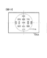
<測距エリアの配置>
第二の実施形態において設定する測距エリアについて、図13−図15を参照して説明する。図13は、専用AF素子207Aを用いて焦点検出する際の測距エリア(専用AF素子207Aに含まれるイメージセンサが像をサンプリングする領域)を示す図であり、測距エリアに対応する位置を撮影画面100A上に表したものである。
<Range of ranging area>
The ranging area set in the second embodiment will be described with reference to FIGS. FIG. 13 is a diagram showing a distance measurement area (area in which the image sensor included in the
図13において、13個の測距エリアからなる測距エリア群71Aが示されている。専用素子AF回路109は、13個の測距エリアのそれぞれについてデフォーカス量を算出し得る。
In FIG. 13, a distance measuring
図14は、撮像素子212Aを用いて焦点検出する際の測距エリア(撮像面内で焦点検出用画素311が像をサンプリングする領域)を示す図である。図14において、撮像面の中央寄りに、8個の測距エリアからなる測距エリア群81Aが示されている。撮像素子AF回路108は、8個の測距エリアのそれぞれについてデフォーカス量を算出し得る。
FIG. 14 is a diagram illustrating a distance measurement area (a region where the
図15は、専用AF素子207Aによる測距エリア群71Aと、撮像素子212Aによる測距エリア群81Aとを重ね合わせた図である。本実施形態では、専用AF素子207Aによる測距エリア群71Aと、撮像素子212Aによる測距エリア群81Aとがそれぞれ撮影画面中央寄りに、かつ測距エリア群71Aおよび81Aが重複しないように、高密度で配設される。
FIG. 15 is a diagram in which the ranging
ミラーダウン状態で行う撮像素子AFによる測距エリア群81Aを撮影画面中央寄りにする(撮影光学系210の光軸に近づける)ことは、撮像素子212Aへ被写体光束を半透過させるメインミラー203やサブミラー204Aを小型化する上で好適である。
Setting the distance measuring
ミラーダウン状態で撮像素子AFを行う場合、メインミラー203とサブミラー104Aを半透過した光束を撮像素子212Aで捉える。これに対し、実際の撮影はミラーアップ状態で行うため、撮像素子212Aには両ミラーを透過しない光束が入射する。このため、測距時と撮影時とでは撮像素子212Aまでの光路長に差が生じる。
When the image sensor AF is performed in the mirror-down state, the light flux that has been semi-transmitted through the
本実施形態では、上記光路差に起因する誤差を抑えるため、各ミラー203、204Aの厚さと屈折率とを用いてあらかじめ算出した光路差に基づいてオフセット情報を用意しておき、撮像素子AF回路108がデフォーカス量を演算する際に上記オフセット情報を用いて補正を行う。
In the present embodiment, in order to suppress the error due to the optical path difference, offset information is prepared based on the optical path difference calculated in advance using the thicknesses and refractive indexes of the
第二の実施形態では、第一の実施形態と同様に、切替レバー51の設定状態に応じて専用素子AFを行うか、あるいは撮像素子AFを行うかを決定する。また、変形例1のように、指示された測距エリアに応じて専用素子AFを行うか、あるいは撮像素子AFを行うかを決定してもよい。
In the second embodiment, as in the first embodiment, whether to perform the dedicated element AF or the image sensor AF is determined according to the setting state of the switching
以上説明した第二の実施形態によれば、次の作用効果が得られる。
(1)焦点検出装置の撮像素子AF回路108は、撮影画面における所定領域の内側に対応する撮像素子212の焦点検出用の画素列からの信号を用いて位相差情報を演算するようにしたので、専用素子AF回路109が検出対象とする領域のさらに内側について位相差情報が得られる。具体的には、専用AF素子207Aによる測距エリア群71Aと、撮像素子212Aによる測距エリア群81Aとがそれぞれ撮影画面中央寄りに、かつ測距エリア群71Aおよび81Aが重複しないように、高密度で配設したことで、多点において適切に位相差情報が得られるようになる。
According to the second embodiment described above, the following operational effects can be obtained.
(1) The image
(2)電子カメラは、入射された光束を折り曲げるとともに透過させる半透過性のミラー203、204Aと、撮影光学系210を通過した光束の光路上の第1位置(ミラーダウン状態)と光路外の第2位置(ミラーアップ状態)との間でミラー203、204Aを移動させるミラー機構215と、撮像素子AF回路108、撮像素子212および専用素子AF回路209、専用AF素子207の少なくとも一方が焦点調節状態を検出する場合はミラー203、204Aを第1位置へ移動させて光束を撮像素子AF回路108、撮像素子212および専用素子AF回路209、専用AF素子207の双方へ導き、撮影時はミラー203、204Aを第2位置へ移動させて光束を撮像素子AF回路108、撮像素子212のみへ導くようにミラー機構215を制御するマイクロコンピュータ−101と、撮像素子AF回路108、撮像素子212または専用素子AF回路209、専用AF素子207によって検出された焦点調節状態に基づいて、撮影光学系210を合焦させるための光学系駆動信号を発するマイクロコンピュータ−101と、を備えるようにした。これにより、ミラー203、204Aが第1位置の状態において、撮像素子AFおよび専用素子AFの双方を行うことができるから、撮影待機状態で多くの検出点において測距が行える。また、全ての検出点について専用素子AF回路209、専用AF素子207で行う場合に比べて、検出点を高密度で配設できるようになる。
(2) The electronic camera bends and transmits the incident light beam, and transmits
(変形例3)
撮影準備状態、すなわちミラーダウン状態において撮像素子AFおよび専用素子AFの双方を行うことは、いわゆるダイナミックAF制御にも好適である。ダイナミックAF制御は、撮影者によって指示された測距エリアについて算出されたデフォーカス量に基づいてフォーカス調節を行い、注目被写体がその測距エリアから外れたと判断した場合には、注目被写体の移動先の新たな測距エリアについて算出されたデフォーカス量に基づいてフォーカス調節を行うAF制御手法である。
(Modification 3)
Performing both the image sensor AF and the dedicated element AF in the shooting preparation state, that is, the mirror-down state is also suitable for so-called dynamic AF control. In the dynamic AF control, focus adjustment is performed based on the defocus amount calculated for the distance measurement area instructed by the photographer. This AF control method performs focus adjustment based on the defocus amount calculated for the new distance measurement area.
この場合のマイクロコンピュータ101は、撮像素子AF回路108または専用素子AF回路109においてデフォーカス量の変化から注目被写体がその測距エリアから外れたと判断された場合、もとの測距エリアの周辺に位置する複数の他の測距エリアについてデフォーカス量を算出させる。この場合、図15に示される専用AF素子207Aによる測距エリア群71Aと、撮像素子212Aによる測距エリア群81Aとをそれぞれ使い、複数の測距エリアについて算出した各デフォーカス量に基づいて、これら複数の測距エリアの中から注目被写体が移動したと推測される測距エリアを決定し、そこでの測距制御に切替る。
In this case, when the imaging
つまり、専用AF素子207Aによる測距エリアに決定した場合は専用素子AF回路109にAF処理を行わせ、撮像素子212Aによる測距エリアに決定した場合は撮像素子AF回路108にAF処理を行わせる。変形例3によれば、撮像素子AFおよび専用素子AFを複合してダイナミックAF制御することで、移動する被写体に対し適切にピント合わせを行える。
That is, when the AF area is determined by the
(変形例4)
ミラーアップ時におけるデフォーカス量の検出に用いる測距エリア数を増やしてもよい。図16−図18は、変形例4における測距エリアを説明する図である。図16は、専用AF素子207Aを用いて焦点検出する際の測距エリア(専用AF素子207Aに含まれるイメージセンサが像をサンプリングする領域)を示す図であり、測距エリアに対応する位置を撮影画面100A上に表したものである。
(Modification 4)
You may increase the number of ranging areas used for the detection of the defocus amount at the time of mirror up. FIG. 16 to FIG. 18 are diagrams for explaining the distance measuring area in the fourth modification. FIG. 16 is a diagram showing a distance measurement area (area where the image sensor included in the
図16において、13個の測距エリアからなる測距エリア群71Aが示されている。専用素子AF回路109は、13個の測距エリアのそれぞれについてデフォーカス量を算出し得る。
In FIG. 16, a distance measuring
図17は、撮像素子212Bを用いて焦点検出する際の測距エリア(撮像面内で焦点検出用画素311が像をサンプリングする領域)を示す図である。図17において、撮像面の中央寄りに、8個の測距エリアからなる測距エリア群81Aが示されている。また、測距エリア群81Aを挟んで左右に、それぞれ10個の測距エリアからなる測距エリア群81、82が示されている。撮像素子AF回路108は、8+10+10=28個の測距エリアのそれぞれについてデフォーカス量を算出し得る。各測距エリアの長さ・幅およびサンプリングピッチは、マイクロレンズ10のサイズ・配列長・配列ピッチによって決まる。
FIG. 17 is a diagram illustrating a distance measurement area (a region where the
図18は、専用AF素子207Aによる測距エリア群71Aと、撮像素子212Bによる測距エリア群81A、81および82とを重ね合わせた図である。変形例4では、専用AF素子207Aによる測距エリア群71Aと、撮像素子212Bによる測距エリア群81A、81および82とが重複しないように、高密度で配設される。
FIG. 18 is a diagram in which the ranging
ミラーダウン状態で行う撮像素子AFによる測距エリア群81Aを撮影画面中央寄りにする(撮影光学系210の光軸に近づける)ことは、撮像素子212Aへ被写体光束を透過させるメインミラー203やサブミラー204Aを小型化する上で好適である。
Setting the distance measuring
一方、撮像素子212による測距エリアとして、撮像面の中央を挟んで左右にそれぞれ測距エリア群81、82を設けたので、専用AF素子207による焦点検出では困難な撮影画面の周辺からもデフォーカス量が得られる。このため、撮影画面の周辺に位置する被写体を対象に合焦させることができる。
On the other hand, distance measuring
以上の説明はあくまで一例であり、上記の実施形態の構成に何ら限定されるものではない。 The above description is merely an example, and is not limited to the configuration of the above embodiment.
51…切替レバー
101…マイクロコンピュータ
108…撮像素子AF回路
109…専用素子AF回路
201…カメラ本体
202…レンズ鏡筒
203…メインミラー
204…サブミラー
205…メカニカルシャッター
207…専用AF素子
210…撮影光学系
212…撮像素子
DESCRIPTION OF
Claims (12)
前記第1の焦点検出手段とは別に設けられており、前記撮影光学系の異なる領域を通過した一対の焦点検出用光束によって得られる一対の像の位相差情報に基づいて、前記撮影光学系による焦点調節状態を検出する第2の焦点検出手段と、を有し、
前記第2の焦点検出手段は、撮影画面内の所定領域に対応する一対の焦点検出用光束に基づく位相差情報を取得し、
前記第1の焦点検出手段は、前記撮影画面内の前記所定領域とは異なる領域に対応する位置に存在する、前記撮像素子上の前記焦点検出用の画素列からの信号を用いて前記位相差情報を演算することを特徴とする焦点検出装置。 A pair of images having an image pickup and focus detection image sensor including a focus detection pixel array, and output signals picked up by the image sensor through a photographing optical system and using signals from the focus detection pixel array First focus detection means for calculating the phase difference information of the first optical system and detecting a focus adjustment state by the photographing optical system based on the phase difference information;
Based on phase difference information of a pair of images obtained by a pair of focus detection light beams that are provided separately from the first focus detection unit and that have passed through different regions of the shooting optical system, Second focus detection means for detecting a focus adjustment state,
The second focus detection unit obtains phase difference information based on a pair of focus detection light beams corresponding to a predetermined region in the photographing screen;
The first focus detection unit uses the signal from the focus detection pixel array on the image sensor, which is present at a position corresponding to an area different from the predetermined area in the imaging screen, to detect the phase difference. A focus detection apparatus characterized by calculating information.
前記第2の焦点検出手段の検出対象領域である前記所定領域は、前記撮影画面における略中央を含む領域であることを特徴とする焦点検出装置。 The focus detection apparatus according to claim 1,
The focus detection apparatus according to claim 1, wherein the predetermined area which is a detection target area of the second focus detection unit is an area including a substantial center of the photographing screen.
前記第1の焦点検出手段は、前記撮影画面における前記所定領域の外側に対応する前記撮像素子の前記焦点検出用の画素列からの信号を用いて前記位相差情報を演算することを特徴とする焦点検出装置。 The focus detection apparatus according to claim 2,
The first focus detection unit calculates the phase difference information using a signal from the focus detection pixel column of the image sensor corresponding to the outside of the predetermined region on the photographing screen. Focus detection device.
前記第1の焦点検出手段は、前記撮影画面における前記所定領域の内側に対応する前記撮像素子の前記焦点検出用の画素列からの信号を用いて前記位相差情報を演算することを特徴とする焦点検出装置。 The focus detection apparatus according to claim 2,
The first focus detection means calculates the phase difference information using a signal from the focus detection pixel column of the image sensor corresponding to the inside of the predetermined area on the imaging screen. Focus detection device.
前記第1の焦点検出手段は、前記撮影画面における前記所定領域の内側および外側に対応する前記撮像素子の前記焦点検出用の画素列からの信号を用いて前記位相差情報を演算することを特徴とする焦点検出装置。 The focus detection apparatus according to claim 2,
The first focus detection unit calculates the phase difference information using a signal from the focus detection pixel column of the imaging element corresponding to the inside and the outside of the predetermined area on the imaging screen. Focus detection device.
操作部材からの操作信号に応じて、前記第1の焦点検出手段または前記第2の焦点検出手段を選ぶ選択手段をさらに備えることを特徴とする焦点検出装置。 In the focus detection apparatus according to any one of claims 1 to 5,
The focus detection apparatus further comprising selection means for selecting the first focus detection means or the second focus detection means in response to an operation signal from an operation member.
前記操作部材は、前記第1の焦点検出手段または前記第2の焦点検出手段を択一的に切替えるための操作信号を発し、
前記選択手段は、前記操作信号が示す焦点検出手段を選ぶことを特徴とする焦点検出装置。 The focus detection apparatus according to claim 6,
The operation member emits an operation signal for selectively switching the first focus detection means or the second focus detection means;
The focus detection apparatus, wherein the selection means selects a focus detection means indicated by the operation signal.
前記第2の焦点検出手段は、前記撮影画面において前記位相差情報を取得し得る第2焦点検出エリアを複数有し、
前記第1の焦点検出手段は、前記撮像素子の前記焦点検出用の画素列の位置を前記撮影画面に対応させた焦点検出エリアであって、前記位相差情報を取得し得る第1焦点検出エリアを複数有し、
前記操作部材は、前記複数の第1焦点検出エリアまたは前記複数の第2焦点検出エリアのうち1つの焦点検出エリアを択一的に切替えるための操作信号を発し、
前記選択手段は、選ばれた焦点検出エリアに対応する焦点検出手段を選ぶことを特徴とする焦点検出装置。 The focus detection apparatus according to claim 6,
The second focus detection means has a plurality of second focus detection areas from which the phase difference information can be acquired on the shooting screen,
The first focus detection unit is a focus detection area in which the position of the focus detection pixel column of the image sensor is made to correspond to the shooting screen, and the first focus detection area can acquire the phase difference information. A plurality of
The operation member emits an operation signal for selectively switching one focus detection area among the plurality of first focus detection areas or the plurality of second focus detection areas,
The focus detection apparatus characterized in that the selection means selects a focus detection means corresponding to the selected focus detection area.
入射された光束を折り曲げる光学部材と、
前記撮影光学系を通過した光束の光路上の第1位置と前記光路外の第2位置との間で前記光学部材を移動させる光学部材移動機構と、
前記第1の焦点検出手段が焦点調節状態を検出する場合および撮影時は前記光学部材を前記第2位置外へ移動させて前記光束を前記第1の焦点検出手段へ導き、前記第2の焦点検出手段が焦点調節状態を検出する場合は前記光学部材を前記第1位置へ移動させて前記光束を前記第2の焦点検出手段へ導くように前記光学部材移動機構を制御する駆動制御手段と、
前記第1の焦点検出手段または前記第2の焦点検出手段によって検出された焦点調節状態に基づいて、前記撮影光学系を合焦させるための光学系駆動信号を発する合焦制御手段と、
を備えることを特徴とするカメラ。 The focus detection apparatus according to any one of claims 1 to 5,
An optical member that bends the incident light beam;
An optical member moving mechanism that moves the optical member between a first position on the optical path of a light beam that has passed through the photographing optical system and a second position outside the optical path;
When the first focus detection unit detects the focus adjustment state and during photographing, the optical member is moved out of the second position to guide the light beam to the first focus detection unit, and the second focus. Drive control means for controlling the optical member moving mechanism to move the optical member to the first position and to guide the light beam to the second focus detection means when the detection means detects the focus adjustment state;
Focusing control means for generating an optical system drive signal for focusing the photographing optical system based on a focus adjustment state detected by the first focus detection means or the second focus detection means;
A camera comprising:
前記駆動制御手段は、前記撮像素子が連続的撮影画像を取得する連続撮影を行う場合には、前記第1位置と前記第2位置との間で前記光学部材を交互に移動せしめ、
前記合焦制御手段は、前記第1焦点検出手段と前記第2焦点検出手段とにより交互に検出された焦点調節状態に基づいて前記撮影光学系を合焦制御することを特徴とするカメラ。 The camera according to claim 9,
The drive control means is configured to move the optical member alternately between the first position and the second position when performing continuous shooting in which the image sensor acquires continuous shot images.
The camera according to claim 1, wherein the focusing control unit controls the focusing of the photographing optical system based on a focus adjustment state detected alternately by the first focus detection unit and the second focus detection unit.
入射された光束を折り曲げるとともに透過させる半透過性の光学部材と、
前記撮影光学系を通過した光束の光路上の第1位置と前記光路外の第2位置との間で前記光学部材を移動させる光学部材移動機構と、
前記第1の焦点検出手段および前記第2の焦点検出手段の少なくとも一方が焦点調節状態を検出する場合は前記光学部材を前記第1位置へ移動させて前記光束を前記第1の焦点検出手段および前記第2の焦点検出手段の双方へ導き、撮影時は前記光学部材を前記第2位置へ移動させて前記光束を前記第1の焦点検出手段のみへ導くように前記光学部材移動機構を制御する駆動制御手段と、
前記第1の焦点検出手段または前記第2の焦点検出手段によって検出された焦点調節状態に基づいて、前記撮影光学系を合焦させるための光学系駆動信号を発する合焦制御手段と、
を備えることを特徴とするカメラ。 The focus detection apparatus according to any one of claims 1 to 5,
A translucent optical member that bends and transmits the incident light beam; and
An optical member moving mechanism that moves the optical member between a first position on the optical path of a light beam that has passed through the photographing optical system and a second position outside the optical path;
When at least one of the first focus detection means and the second focus detection means detects a focus adjustment state, the optical member is moved to the first position, and the light beam is moved to the first focus detection means and The optical member moving mechanism is controlled such that the optical member is guided to both of the second focus detection means and the optical member is moved to the second position to guide the light beam only to the first focus detection means during photographing. Drive control means;
Focusing control means for generating an optical system drive signal for focusing the photographing optical system based on a focus adjustment state detected by the first focus detection means or the second focus detection means;
A camera comprising:
前記駆動制御手段は、前記撮影画面内の被写体を連続的に追跡する焦点検出モードが選択されている場合には、前記光学部材を前記第1位置に移動せしめておき、
前記合焦制御手段は、前記第1焦点検出手段と前記第2焦点検出手段の両方から得られる焦点調節状態に基づいて前記撮影光学系を合焦制御することを特徴とするカメラ。 The camera according to claim 11,
The drive control means moves the optical member to the first position when a focus detection mode for continuously tracking a subject in the shooting screen is selected,
The camera according to claim 1, wherein the focus control unit controls the focus of the photographing optical system based on a focus adjustment state obtained from both the first focus detection unit and the second focus detection unit.
Priority Applications (1)
| Application Number | Priority Date | Filing Date | Title |
|---|---|---|---|
| JP2011270162A JP2013122494A (en) | 2011-12-09 | 2011-12-09 | Focus detector and camera |
Applications Claiming Priority (1)
| Application Number | Priority Date | Filing Date | Title |
|---|---|---|---|
| JP2011270162A JP2013122494A (en) | 2011-12-09 | 2011-12-09 | Focus detector and camera |
Publications (1)
| Publication Number | Publication Date |
|---|---|
| JP2013122494A true JP2013122494A (en) | 2013-06-20 |
Family
ID=48774492
Family Applications (1)
| Application Number | Title | Priority Date | Filing Date |
|---|---|---|---|
| JP2011270162A Pending JP2013122494A (en) | 2011-12-09 | 2011-12-09 | Focus detector and camera |
Country Status (1)
| Country | Link |
|---|---|
| JP (1) | JP2013122494A (en) |
Cited By (3)
| Publication number | Priority date | Publication date | Assignee | Title |
|---|---|---|---|---|
| JP2016024356A (en) * | 2014-07-22 | 2016-02-08 | 株式会社ニコン | Focus adjustment device and imaging device |
| WO2017135276A1 (en) * | 2016-02-01 | 2017-08-10 | ソニー株式会社 | Controller, control method, and control program |
| CN112714884A (en) * | 2018-07-20 | 2021-04-27 | 株式会社尼康 | Focus detection device, imaging device, and interchangeable lens |
Citations (7)
| Publication number | Priority date | Publication date | Assignee | Title |
|---|---|---|---|---|
| JPH0667088A (en) * | 1992-08-18 | 1994-03-11 | Nikon Corp | Focus detecting device |
| JP2007233032A (en) * | 2006-03-01 | 2007-09-13 | Nikon Corp | Focus adjustment device and imaging device |
| JP2009139807A (en) * | 2007-12-10 | 2009-06-25 | Sony Corp | Imaging device |
| JP2009139795A (en) * | 2007-12-10 | 2009-06-25 | Sony Corp | Imaging device |
| JP2011028177A (en) * | 2009-07-29 | 2011-02-10 | Nikon Corp | Imaging apparatus |
| JP2011112941A (en) * | 2009-11-27 | 2011-06-09 | Nikon Corp | Digital camera |
| JP2012137600A (en) * | 2010-12-27 | 2012-07-19 | Sony Corp | Imaging system, imaging device, and program |
-
2011
- 2011-12-09 JP JP2011270162A patent/JP2013122494A/en active Pending
Patent Citations (7)
| Publication number | Priority date | Publication date | Assignee | Title |
|---|---|---|---|---|
| JPH0667088A (en) * | 1992-08-18 | 1994-03-11 | Nikon Corp | Focus detecting device |
| JP2007233032A (en) * | 2006-03-01 | 2007-09-13 | Nikon Corp | Focus adjustment device and imaging device |
| JP2009139807A (en) * | 2007-12-10 | 2009-06-25 | Sony Corp | Imaging device |
| JP2009139795A (en) * | 2007-12-10 | 2009-06-25 | Sony Corp | Imaging device |
| JP2011028177A (en) * | 2009-07-29 | 2011-02-10 | Nikon Corp | Imaging apparatus |
| JP2011112941A (en) * | 2009-11-27 | 2011-06-09 | Nikon Corp | Digital camera |
| JP2012137600A (en) * | 2010-12-27 | 2012-07-19 | Sony Corp | Imaging system, imaging device, and program |
Cited By (9)
| Publication number | Priority date | Publication date | Assignee | Title |
|---|---|---|---|---|
| JP2016024356A (en) * | 2014-07-22 | 2016-02-08 | 株式会社ニコン | Focus adjustment device and imaging device |
| WO2017135276A1 (en) * | 2016-02-01 | 2017-08-10 | ソニー株式会社 | Controller, control method, and control program |
| CN108603997A (en) * | 2016-02-01 | 2018-09-28 | 索尼公司 | Control device, control method and control program |
| JPWO2017135276A1 (en) * | 2016-02-01 | 2018-11-22 | ソニー株式会社 | Control device, control method, and control program |
| US10686979B2 (en) | 2016-02-01 | 2020-06-16 | Sony Corporation | Control apparatus and control method |
| CN108603997B (en) * | 2016-02-01 | 2021-08-13 | 索尼公司 | Control device, control method and control program |
| JP7036423B2 (en) | 2016-02-01 | 2022-03-15 | ソニーグループ株式会社 | Controls, control methods and control programs |
| CN112714884A (en) * | 2018-07-20 | 2021-04-27 | 株式会社尼康 | Focus detection device, imaging device, and interchangeable lens |
| CN112714884B (en) * | 2018-07-20 | 2023-10-27 | 株式会社尼康 | Focus detection device, shooting device and interchangeable lens |
Similar Documents
| Publication | Publication Date | Title |
|---|---|---|
| JP5195506B2 (en) | Imaging apparatus and image composition method | |
| JP5034556B2 (en) | Focus detection apparatus and imaging apparatus | |
| JP4766133B2 (en) | Imaging device | |
| US6377305B2 (en) | Image sensing apparatus | |
| JP5653035B2 (en) | Imaging apparatus, focus detection method, and control method | |
| US20060127080A1 (en) | Digital single-reflex camera | |
| JP2012113189A (en) | Imaging apparatus | |
| JP2017126035A (en) | Imaging apparatus, control method, program, and storage medium | |
| JP5776191B2 (en) | Focus detection apparatus and imaging apparatus | |
| JP2012083584A (en) | Imaging device | |
| JP2012189878A (en) | Imaging apparatus | |
| JP2013122494A (en) | Focus detector and camera | |
| JP2013122495A (en) | Focus detector and camera | |
| JP2012128343A (en) | Camera | |
| JP5966299B2 (en) | FOCUS DETECTION DEVICE AND IMAGING DEVICE HAVING THE SAME | |
| JP2017118212A (en) | Imaging apparatus | |
| JP6561437B2 (en) | Focus adjustment device and imaging device | |
| JP2012108281A (en) | Focus detector and imaging apparatus | |
| JP2005295577A (en) | Imaging device | |
| JP2009081522A (en) | Imaging device | |
| JP2012063681A (en) | Focus detecting device and camera | |
| JP2008039976A (en) | Imaging device | |
| JP5391587B2 (en) | Imaging device | |
| JP2011175172A (en) | Digital camera | |
| JP2009162964A (en) | IMAGING DEVICE AND IMAGING DEVICE CONTROL METHOD |
Legal Events
| Date | Code | Title | Description |
|---|---|---|---|
| A621 | Written request for application examination |
Free format text: JAPANESE INTERMEDIATE CODE: A621 Effective date: 20141202 |
|
| A977 | Report on retrieval |
Free format text: JAPANESE INTERMEDIATE CODE: A971007 Effective date: 20150807 |
|
| A131 | Notification of reasons for refusal |
Free format text: JAPANESE INTERMEDIATE CODE: A131 Effective date: 20150818 |
|
| A02 | Decision of refusal |
Free format text: JAPANESE INTERMEDIATE CODE: A02 Effective date: 20151215 |