JP2012246795A - Power supply control device for vehicle - Google Patents
Power supply control device for vehicle Download PDFInfo
- Publication number
- JP2012246795A JP2012246795A JP2011117353A JP2011117353A JP2012246795A JP 2012246795 A JP2012246795 A JP 2012246795A JP 2011117353 A JP2011117353 A JP 2011117353A JP 2011117353 A JP2011117353 A JP 2011117353A JP 2012246795 A JP2012246795 A JP 2012246795A
- Authority
- JP
- Japan
- Prior art keywords
- temperature
- heater
- oil
- power
- catalyst
- Prior art date
- Legal status (The legal status is an assumption and is not a legal conclusion. Google has not performed a legal analysis and makes no representation as to the accuracy of the status listed.)
- Pending
Links
Images



Classifications
-
- Y—GENERAL TAGGING OF NEW TECHNOLOGICAL DEVELOPMENTS; GENERAL TAGGING OF CROSS-SECTIONAL TECHNOLOGIES SPANNING OVER SEVERAL SECTIONS OF THE IPC; TECHNICAL SUBJECTS COVERED BY FORMER USPC CROSS-REFERENCE ART COLLECTIONS [XRACs] AND DIGESTS
- Y02—TECHNOLOGIES OR APPLICATIONS FOR MITIGATION OR ADAPTATION AGAINST CLIMATE CHANGE
- Y02A—TECHNOLOGIES FOR ADAPTATION TO CLIMATE CHANGE
- Y02A50/00—TECHNOLOGIES FOR ADAPTATION TO CLIMATE CHANGE in human health protection, e.g. against extreme weather
- Y02A50/20—Air quality improvement or preservation, e.g. vehicle emission control or emission reduction by using catalytic converters
Landscapes
- Hybrid Electric Vehicles (AREA)
- Exhaust Gas After Treatment (AREA)
- Lubrication Of Internal Combustion Engines (AREA)
- Electric Propulsion And Braking For Vehicles (AREA)
Abstract
【課題】オイルヒータへの通電を的確に行いつつ、潤滑油の劣化及びオイルヒータの故障を抑制する。
【解決手段】車両の通電制御装置は、内燃機関における潤滑経路に設けられるオイルヒータと、オイルヒータに通電可能である蓄電手段とを備える車両において、オイルヒータへの通電を制御する。該通電制御装置は、オイルヒータを通過するオイルの温度たるオイル温度、及びオイルヒータ本体の温度たるヒータ温度のうちの少なくとも一方を特定する第1温度特定手段と、蓄電手段の蓄電残量が所定量より大きい場合、オイル温度及びヒータ温度のうちの少なくとも一方に応じて、オイルヒータへの通電を行う通電制御手段とを備える。
【選択図】図3The present invention suppresses deterioration of lubricating oil and failure of an oil heater while accurately energizing an oil heater.
An energization control device for a vehicle controls energization of an oil heater in a vehicle including an oil heater provided in a lubrication path in an internal combustion engine and an electric storage unit capable of energizing the oil heater. The energization control device includes: a first temperature specifying unit that specifies at least one of an oil temperature that is an oil temperature that passes through the oil heater and a heater temperature that is a temperature of the oil heater body; When larger than a fixed amount, it comprises an energization control means for energizing the oil heater according to at least one of the oil temperature and the heater temperature.
[Selection] Figure 3
Description
本発明は、例えばオイルヒータ等の、潤滑油を加熱する潤滑油加熱装置を備える車両において、該潤滑油加熱装置への通電を制御する通電制御装置の技術分野に関する。 The present invention relates to a technical field of an energization control device that controls energization to a lubricating oil heating device in a vehicle including a lubricating oil heating device that heats lubricating oil, such as an oil heater.
この種の装置として、電気自動車において、バッテリ残容量が設定値より大きい場合であって、潤滑油の油温が所定の温度より低い場合、オイルヒータへの通電を行い、潤滑油を加熱するものが提案されている(例えば、特許文献1参照)。特許文献1では、潤滑油を加熱する場合、油温に応じた通電量がオイルヒータに流される。 As this type of device, in an electric vehicle, when the remaining battery capacity is larger than a set value and the lubricating oil temperature is lower than a predetermined temperature, the oil heater is energized to heat the lubricating oil. Has been proposed (see, for example, Patent Document 1). In Patent Document 1, when the lubricating oil is heated, an energization amount corresponding to the oil temperature is passed to the oil heater.
また、エンジンオイルを加熱するヒータ、及び/又は触媒を活性化するためのヒータへの電力供給量を制御する装置が提案されている(例えば、特許文献2参照)。特許文献2では、減速時、発電機の出力電圧が高電圧に設定されると共に、発電機の発電能力に余裕がある場合、ヒータへの電力供給量が増加される。
In addition, a device for controlling the amount of power supplied to a heater for heating engine oil and / or a heater for activating a catalyst has been proposed (for example, see Patent Document 2). In
また、排気浄化装置と、該排気浄化装置を含むエンジン部分の加熱を行う電気加熱手段とを備えるハイブリッド車両において、車両の要求駆動力、及びバッテリの充電残量に基づいてエンジンの運転が必要と判断された場合、要求駆動力、充電残量及びエンジン各部の温度に基づいて、電気加熱手段の通電制御を行うものが提案されている(例えば、特許文献3参照)。特許文献3では、充電残量が所定値以下である場合、エンジン始動に最低限必要なグロープラグの通電制御のみが行われる。また、充電残量が所定値を上回り、充電上限閾値未満である場合、グロープラグの通電制御に加え、排気浄化性能を高めるための電気加熱手段の通電制御が行われる。更には、充電残量が充電上限閾値以上である場合、グロープラグ及び電気加熱手段の通電制御に加え、冷却水加熱用のブロックヒータの通電制御が行われる。尚、これら通電制御は、電気加熱手段及びグロープラグの加熱段階に対応している。
Further, in a hybrid vehicle including an exhaust purification device and an electric heating means for heating an engine portion including the exhaust purification device, the engine needs to be operated based on the required driving force of the vehicle and the remaining charge of the battery. When it is determined, there has been proposed one that performs energization control of the electric heating means based on the required driving force, the remaining charge amount, and the temperature of each part of the engine (for example, see Patent Document 3). In
また、電熱触媒を備えるハイブリッド車両において、減速時に電熱触媒を暖機する際、少なくともモータの回生電力を電熱触媒に供給するものが提案されている(例えば、特許文献4参照)。特許文献4では、電熱触媒の温度、及びバッテリの充電量に基づいて、モータと電熱触媒とバッテリとの間の電力供給回路が切り替え可能である。 Further, in a hybrid vehicle including an electrothermal catalyst, there has been proposed one that supplies at least the regenerative power of the motor to the electrothermal catalyst when the electrothermal catalyst is warmed up during deceleration (see, for example, Patent Document 4). In Patent Document 4, the power supply circuit among the motor, the electrothermal catalyst, and the battery can be switched based on the temperature of the electrothermal catalyst and the charge amount of the battery.
また、ハイブリッド車両において、バッテリの充電量が基準値より大きい場合、エンジンオイルの温度が摂氏80度から85度の間に保たれるように、エンジンオイルをヒータで加熱するものが提案されている(例えば、特許文献5参照)。 Moreover, in a hybrid vehicle, when the charge amount of a battery is larger than a reference value, the engine oil is heated by a heater so that the temperature of the engine oil is maintained between 80 degrees Celsius and 85 degrees Celsius. (For example, refer to Patent Document 5).
また、ハイブリッド車両において、バッテリの充電力が第1閾値より大きい、又は第2閾値より小さい場合、モータの回生電力を直接加熱触媒に供給し、バッテリの充電量が第1閾値より小さく第2閾値より大きい場合、少なくとも回生電力をバッテリに充電し、バッテリの蓄電電力を加熱触媒に供給するものが提案されている(例えば、特許文献6参照)。特許文献6では、加熱触媒の温度が温度閾値より高い場合、加熱触媒への回生電力の供給が停止される。
In the hybrid vehicle, when the charging power of the battery is larger than the first threshold value or smaller than the second threshold value, the regenerative electric power of the motor is directly supplied to the heating catalyst, and the charge amount of the battery is smaller than the first threshold value. In the case where it is larger, there has been proposed one in which at least regenerative electric power is charged in the battery and the stored electric power of the battery is supplied to the heating catalyst (for example, see Patent Document 6). In
更には、エンジン水温及びエンジン油温に応じて、冷却水循環経路切替弁及びオイル流量制御弁、並びにオイルヒータへの通電を制御するものが提案されている(例えば、特許文献7参照)。 In addition, a cooling water circulation path switching valve, an oil flow rate control valve, and a valve that controls energization to the oil heater according to the engine water temperature and the engine oil temperature have been proposed (see, for example, Patent Document 7).
上記特許文献1に記載の装置では、オイルヒータへの通電量が油温に対応している。このため、例えば通電直前に、余熱が冷めない内に測定された油温に対応する通電量がヒータに供給されると、油温或いはオイルヒータ本体が過上昇することで、潤滑油の劣化やオイルヒータの故障が生じ兼ねないといった技術的問題点がある。 In the apparatus described in Patent Document 1, the energization amount to the oil heater corresponds to the oil temperature. For this reason, for example, if an energization amount corresponding to the measured oil temperature is supplied to the heater immediately before the energization is not cooled, the oil temperature or the oil heater body rises excessively, which may cause deterioration of the lubricating oil. There is a technical problem that an oil heater may fail.
本発明は、例えば上述した問題点に鑑みなされたものであり、オイルヒータへの通電を的確に行いつつ、潤滑油の劣化及びオイルヒータの故障を抑制し得る車両の通電制御装置を提供することを課題とする。 The present invention has been made in view of the above-described problems, for example, and provides a vehicle energization control device capable of suppressing deterioration of the lubricating oil and failure of the oil heater while accurately energizing the oil heater. Is an issue.
上述した課題を解決するために、本発明に係る第1の車両の通電制御装置は、内燃機関における潤滑経路に設けられるオイルヒータと、該オイルヒータに通電可能である蓄電手段とを備える車両において、前記オイルヒータへの通電を制御する通電制御装置であって、前記オイルヒータを通過するオイルの温度たるオイル温度、及び前記オイルヒータ本体の温度たるヒータ温度のうちの少なくとも一方を特定する第1温度特定手段と、前記蓄電手段の蓄電残量が所定量より大きい場合、前記特定されたオイル温度及びヒータ温度のうちの少なくとも一方に応じて、前記オイルヒータへの通電を行う通電制御手段とを備える。 In order to solve the above-described problem, a first vehicle energization control device according to the present invention is a vehicle including an oil heater provided in a lubrication path in an internal combustion engine, and power storage means capable of energizing the oil heater. An energization control device for controlling energization to the oil heater, wherein the first is for specifying at least one of an oil temperature as a temperature of oil passing through the oil heater and a heater temperature as a temperature of the oil heater body. A temperature specifying unit; and an energization control unit configured to energize the oil heater according to at least one of the specified oil temperature and heater temperature when the remaining amount of power stored in the power storage unit is greater than a predetermined amount. Prepare.
本発明に係るオイルヒータは、潤滑油(以下、「オイル」と称する)を巡回させるための潤滑経路に設けられており、該潤滑経路を通って内燃機関における回転部及び摺動部に供給されるオイルを昇温可能に構成される。オイルヒータは、一般的な特性として、オイルを加熱する形態として、比較的低い電力で長時間の通電を行うよりも、例えば内燃機関の始動時等に、比較的高い電力で短時間の通電を行った方が、同一のエネルギーを用いた場合であってもオイルを効果よく暖めることが可能である。オイルは、一般的には、摂氏90度前後で使用される場合、劣化し難い。 The oil heater according to the present invention is provided in a lubricating path for circulating lubricating oil (hereinafter referred to as “oil”), and is supplied to the rotating part and the sliding part in the internal combustion engine through the lubricating path. The oil can be heated up. As a general characteristic, the oil heater is configured to heat oil for a short time with a relatively high power, for example, when starting an internal combustion engine, rather than performing a long time with a relatively low power. Even if the same energy is used, the oil can be effectively warmed. Oil is generally difficult to degrade when used at around 90 degrees Celsius.
本発明に係る蓄電手段は、例えばエンジン及び/又は発電機からの発電電力を充電可能であると共に、例えばオイルヒータやヒータ付触媒等の電機に対し蓄電電力(言い換えれば、通電電力)を放電可能に構成されるバッテリを示す。蓄電手段について、一般的な特性として、蓄電量(以下、適宜「蓄電残量」と称する)が全蓄電量のうちの60パーセント程度の状態で蓄電手段を使用する場合、実際の使用可能期間が本来の期間より短くなり、劣化が早まる場合がある。ここで、オイルヒータに係る「通電を行う」とは、オイルヒータに対し予め設定された条件で電力供給を行うことを示す。この電力供給に係る「条件」とは、具体的には、少なくともオイル温度及びヒータ温度が各々の上限温度を超えないように設定される電力量及びその供給時間を示す。こうした条件では、設定される電力量及び/又はその供給時間を縮小した通電が行われてもよい。 The power storage means according to the present invention can charge, for example, generated power from an engine and / or generator, and can discharge stored power (in other words, energized power) to an electric machine such as an oil heater or a heater-equipped catalyst. The battery comprised is shown. As a general characteristic of the power storage means, when the power storage means is used in a state in which the power storage amount (hereinafter referred to as “the remaining power storage amount” as appropriate) is about 60% of the total power storage amount, the actual usable period is It may be shorter than the original period, and deterioration may be accelerated. Here, “energizing” relating to the oil heater means that electric power is supplied to the oil heater under a preset condition. Specifically, the “condition” relating to the power supply indicates the amount of power set so that at least the oil temperature and the heater temperature do not exceed the respective upper limit temperatures, and the supply time thereof. Under such conditions, energization may be performed in which the set power amount and / or the supply time thereof is reduced.
本発明に係る第1温度特定手段は、オイル温度及びヒータ温度のうちの少なくとも一方を特定する。ここで、オイル温度及びヒータ温度に係る「特定」とは、例えば温度センサ等の温度計測器を用いて各々の温度が直接に出力される、或いは一又は複数のパラメータを取得し所定の方程式を用いて各々の温度が算出或いは推定されることを示す。上記温度計測器、及びパラメータ取得のための計器等は、例えばオイルヒータの近傍で、潤滑経路におけるオイルヒータの上流側及び下流側のいずれに設置されてもよい。 The first temperature specifying means according to the present invention specifies at least one of the oil temperature and the heater temperature. Here, the “specific” related to the oil temperature and the heater temperature means that each temperature is directly output using a temperature measuring device such as a temperature sensor, or a predetermined equation is obtained by acquiring one or a plurality of parameters. Used to indicate that each temperature is calculated or estimated. The temperature measuring instrument, the instrument for parameter acquisition, and the like may be installed, for example, in the vicinity of the oil heater, either upstream or downstream of the oil heater in the lubrication path.
本発明に係る通電制御手段は、例えば、一又は複数のCPU(Central Processing Unit)、MPU(Micro Processing Unit)、各種プロセッサ又は各種コントローラ、或いは更にROM(Read Only Memory)、RAM(Random Access Memory)、バッファメモリ又はフラッシュメモリ等の各種記憶手段等を適宜に含み得る、単体或いは複数のECU(Electronic Controlled Unit)等の各種処理ユニット、各種コントローラ或いはマイコン装置等各種コンピュータシステム等の形態を採り得る。 The energization control means according to the present invention includes, for example, one or a plurality of CPUs (Central Processing Units), MPUs (Micro Processing Units), various processors or various controllers, or ROM (Read Only Memory), RAM (Random Access Memory). In addition, various processing units such as a single or a plurality of ECUs (Electronic Controlled Units), various controllers, or various computer systems such as a microcomputer device may be employed.
本発明の第1の車両の通電制御装置に係る通電制御手段は、蓄電手段の蓄電残量が所定量より大きい場合、第1温度特定手段により特定されたオイル温度及びヒータ温度のうちの少なくとも一方に応じて、オイルヒータへの通電を行う。ここで、蓄電残量に係る「所定量」とは、蓄電手段の劣化に影響を及ぼさない蓄電残量の最低値、及び通電のための供給電力に基づいて決められ、通電前に、少なくとも該供給電力に相当する蓄電残量を保持するか否かを判定するための蓄電残量の判定値である。また、オイル温度及びヒータ温度に係る「応じて」とは、オイル温度又はヒータ温度と、各々の所定温度とを比較した結果に対応して通電を行うことを示す。具体的には、オイル温度が一の所定温度より低い場合、オイルヒータへの通電を行う。又はヒータ温度が他の所定温度より低い場合、該通電を行う。又はオイル温度が一の所定温度より低く、且つヒータ温度が他の所定温度より低い場合、該通電を行う。 The energization control unit according to the first vehicle energization control device of the present invention is configured so that at least one of the oil temperature and the heater temperature specified by the first temperature specifying unit is determined when the remaining storage amount of the storage unit is greater than a predetermined amount. The oil heater is energized accordingly. Here, the “predetermined amount” related to the remaining amount of electricity is determined based on the minimum value of the remaining amount of electricity that does not affect the deterioration of the electricity storage means, and the supplied power for energization. It is a determination value of the remaining amount of electricity for determining whether to retain the remaining amount of electricity stored corresponding to the supplied power. “According to the oil temperature and the heater temperature” indicates that energization is performed in accordance with a result of comparing the oil temperature or the heater temperature with each predetermined temperature. Specifically, when the oil temperature is lower than one predetermined temperature, the oil heater is energized. Alternatively, when the heater temperature is lower than another predetermined temperature, the energization is performed. Alternatively, when the oil temperature is lower than one predetermined temperature and the heater temperature is lower than another predetermined temperature, the energization is performed.
本発明の第1の車両の通電制御装置によれば、蓄電残量が所定量より大きい場合、第1温度特定手段により、オイル温度及びヒータ温度のうちの少なくとも一方が特定される。すると、通電制御手段により、オイル温度に応じてオイルヒータへの通電を行うことで、オイルが過上昇することがなく、オイルの劣化を抑制することが可能である。又は通電制御手段により、ヒータ温度に応じてヒータへの通電を行うことで、オイルヒータ本体が過上昇することがなく、オイルヒータの故障を抑制することが可能である。又は通電制御手段により、オイル温度及びヒータ温度に応じてヒータへの通電を行う。この際、オイル温度及びヒータ温度に基づいて、オイルヒータへの通電に最適なタイミングを取ると共に、オイル温度及びヒータ温度に基づいて、オイル温度及びヒータ温度が各々の上限温度を超えない程の適当な通電電力を供給する。このように、最適な通電タイミングで適当な通電電力をオイルヒータに供給することで、オイルヒータへの通電を的確に行いつつ、オイルの劣化及びオイルヒータの故障を抑制することが可能である。 According to the first vehicle energization control device of the present invention, when the remaining power amount is larger than the predetermined amount, at least one of the oil temperature and the heater temperature is specified by the first temperature specifying means. Then, the energization control means energizes the oil heater according to the oil temperature, so that the oil does not rise excessively and the deterioration of the oil can be suppressed. Alternatively, by energizing the heater according to the heater temperature by the energization control means, the oil heater main body does not rise excessively, and the failure of the oil heater can be suppressed. Alternatively, the energization control means energizes the heater according to the oil temperature and the heater temperature. At this time, based on the oil temperature and the heater temperature, the optimum timing for energizing the oil heater is taken, and on the basis of the oil temperature and the heater temperature, the oil temperature and the heater temperature are appropriately set so as not to exceed the respective upper limit temperatures. Supplying energized power. In this way, by supplying appropriate energization power to the oil heater at the optimal energization timing, it is possible to suppress oil deterioration and oil heater failure while accurately energizing the oil heater.
本発明に係る第1の車両の通電制御装置の一の態様では、前記特定されたオイル温度が第1所定温度より低いか否かを判定する第1判定手段と、前記特定されたヒータ温度が第2所定温度より低いか否かを判定する第2判定手段とを更に備え、前記特定されたオイル温度は、前記潤滑経路における前記オイルヒータより上流を通過する前記オイルの温度であって、前記通電制御手段は、前記第1判定手段により前記オイル温度が前記第1所定温度より低いと判定され、且つ前記第2判定手段により前記ヒータ温度が前記第2所定温度より低いと判定される場合、前記オイルヒータへの通電を行う。 In one aspect of the first vehicle energization control device according to the present invention, the first determination means for determining whether or not the specified oil temperature is lower than a first predetermined temperature, and the specified heater temperature is Second determining means for determining whether the temperature is lower than a second predetermined temperature, wherein the specified oil temperature is a temperature of the oil passing upstream from the oil heater in the lubrication path, and The energization control means, when the first determination means determines that the oil temperature is lower than the first predetermined temperature, and the second determination means determines that the heater temperature is lower than the second predetermined temperature, The oil heater is energized.
本発明に係る第1判定手段及び第2判定手段の各々は、例えばECU等の処理ユニットであって、通信制御手段と別体に構成されてもいいし、通信制御手段に含まれていてもよい。ここで、第1判定手段に係る「第1所定温度」とは、例えばオイルヒータ上流側を通過するオイルの上限温度であって、通電の要否を判定するための該オイル温度の判定値を示す。また第2判定手段に係る「第2所定温度」とは、例えばヒータの上限温度であって、通電の要否を判定するためのヒータ温度の判定値を示す。このような第1及び第2所定温度について、典型的には、第1所定温度より第2所定温度の方が高い温度をとる。 Each of the first determination means and the second determination means according to the present invention is, for example, a processing unit such as an ECU, and may be configured separately from the communication control means, or may be included in the communication control means. Good. Here, the “first predetermined temperature” according to the first determination means is, for example, the upper limit temperature of the oil passing through the upstream side of the oil heater, and is a determination value of the oil temperature for determining whether energization is necessary. Show. The “second predetermined temperature” related to the second determination means is, for example, an upper limit temperature of the heater, and indicates a determination value of the heater temperature for determining whether energization is necessary. As for such first and second predetermined temperatures, the second predetermined temperature is typically higher than the first predetermined temperature.
この態様によれば、第1判定手段により、オイル温度が第1所定温度より低いと判定され、且つ第2判定手段により、ヒータ温度が第2所定温度より低いと判定されると、通信制御手段により、オイルヒータへの通電が行われる。これにより、最適な通電タイミングで適当な通電量をオイルヒータに供給することで、オイルヒータへの通電を的確に行うことが可能である。言い換えれば、オイルヒータの稼働効率を高めることが可能である。 According to this aspect, when the first determination unit determines that the oil temperature is lower than the first predetermined temperature, and the second determination unit determines that the heater temperature is lower than the second predetermined temperature, the communication control unit Thus, the oil heater is energized. Thereby, it is possible to accurately energize the oil heater by supplying an appropriate energization amount to the oil heater at an optimal energization timing. In other words, the operating efficiency of the oil heater can be increased.
本発明に係る車両の通電制御装置の他の態様では、前記潤滑経路を巡回する前記オイルの流量たるオイル流量を、前記特定されたオイル温度、及び前記内燃機関における機関回転速度に基づいて特定する流量特定手段を更に備え、前記第1温度特定手段は、前記特定されたオイル温度及びオイル流量に基づいて前記ヒータ温度を特定してもよい。 In another aspect of the vehicle energization control device according to the present invention, the oil flow rate that is the flow rate of the oil circulating in the lubrication path is specified based on the specified oil temperature and the engine speed in the internal combustion engine. The apparatus may further include a flow rate specifying unit, and the first temperature specifying unit may specify the heater temperature based on the specified oil temperature and oil flow rate.
本発明に係る流量特定手段は、例えばECU等の処理ユニットであって、通信制御手段と別体に構成されてもいいし、通信制御手段に含まれていてもよい。ここで、流量特定手段に係る「オイル流量」とは、具体的には、潤滑経路において分岐経路を除いた一経路の一断面を単位時間当たりに通過するオイルの質量を示す。また、オイル流量に係る「特定」とは、オイル温度及び機関回転速度をパラメータとし、所定のマップを用いて算出或いは推定することを示す。 The flow rate specifying unit according to the present invention is, for example, a processing unit such as an ECU, and may be configured separately from the communication control unit or may be included in the communication control unit. Here, the “oil flow rate” relating to the flow rate specifying means specifically indicates the mass of oil that passes through one section of one route excluding the branch route in the lubrication route per unit time. Further, “specific” relating to the oil flow rate indicates that calculation or estimation is performed using a predetermined map with the oil temperature and the engine speed as parameters.
この態様によれば、ヒータ温度を特定するべく、先ず流量特定手段により、オイル流量が特定される。すると、特定されたオイル流量、及びオイル温度に基づいて、第1温度特定手段により、ヒータ温度が特定される。これにより、ヒータ温度を特定するための温度計測器を設置する必要がないので、該温度計測器分のコストを削減することが可能である。 According to this aspect, the oil flow rate is first specified by the flow rate specifying means in order to specify the heater temperature. Then, the heater temperature is specified by the first temperature specifying means based on the specified oil flow rate and oil temperature. Thereby, since it is not necessary to install the temperature measuring device for specifying heater temperature, it is possible to reduce the cost for this temperature measuring device.
本発明に係る車両の通電制御装置の他の態様では、前記第1温度特定手段は、前記オイルヒータの抵抗値に基づいて前記ヒータ温度を特定してもよい。 In another aspect of the vehicle energization control apparatus according to the present invention, the first temperature specifying means may specify the heater temperature based on a resistance value of the oil heater.
この態様によれば、第1温度特定手段により、ヒータ温度に応じて変化するオイルヒータの抵抗値に基づいて、ヒータ温度が特定される。ここで、ヒータ温度に係る「特定」とは、オイルヒータの抵抗値をパラメータとし、所定の方程式を用いて算出或いは推定することを示す。これにより、ヒータ温度を特定するための温度計測器を設置する必要がないので、該温度計測器分のコストを削減することが可能である。 According to this aspect, the heater temperature is specified by the first temperature specifying means based on the resistance value of the oil heater that changes according to the heater temperature. Here, “specific” relating to the heater temperature indicates that the resistance value of the oil heater is used as a parameter and is calculated or estimated using a predetermined equation. Thereby, since it is not necessary to install the temperature measuring device for specifying heater temperature, it is possible to reduce the cost for this temperature measuring device.
本発明に係る第2の車両の通電制御装置は、内燃機関における潤滑経路に設けられるオイルヒータと、前記内燃機関における排気経路に設けられるヒータ付触媒と、前記オイルヒータ及び前記ヒータ付触媒のうちの少なくとも一方に通電可能である蓄電手段とを備える車両において、前記オイルヒータ及び前記ヒータ付触媒への通電を制御する通電制御装置であって、前記オイルヒータを通過するオイルの温度たるオイル温度、及び前記オイルヒータ本体の温度たるヒータ温度のうちの少なくとも一方を特定する第1温度特定手段と、前記ヒータ付触媒の温度たる触媒温度を特定する第2温度特定手段と、前記第1温度特定手段により特定されたオイル温度、及び前記第2温度特定手段により特定された触媒温度のうちの少なくとも一方に基づいて、前記オイルヒータ及び前記ヒータ付触媒に対する、前記蓄電手段における供給可能電力の分配を行うための分配比率を特定する分配比率特定手段と、前記特定された分配比率で前記分配が行われるように、前記オイルヒータ及び前記ヒータ付触媒への通電を行う通電制御手段とを備える。 An energization control device for a second vehicle according to the present invention includes an oil heater provided in a lubrication path in an internal combustion engine, a catalyst with a heater provided in an exhaust path in the internal combustion engine, the oil heater, and the catalyst with heater. In a vehicle comprising a power storage means capable of energizing at least one of the above, an energization control device for controlling energization to the oil heater and the catalyst with heater, the oil temperature being the temperature of oil passing through the oil heater, And a first temperature specifying means for specifying at least one of the heater temperatures as the temperature of the oil heater body, a second temperature specifying means for specifying the catalyst temperature as the temperature of the heater-equipped catalyst, and the first temperature specifying means Based on at least one of the oil temperature specified by the second temperature specifying means and the catalyst temperature specified by the second temperature specifying means. And the distribution ratio specifying means for specifying a distribution ratio for distributing the suppliable power in the power storage means to the oil heater and the catalyst with heater, and the distribution is performed at the specified distribution ratio. And an energization control means for energizing the oil heater and the catalyst with heater.
本発明に係るヒータ付触媒は、例えばEHC(Electric Heated Catalyst)等の電気加熱式触媒であって、排気経路に設けられ、該排気経路を通って大気に排出される排ガス中の有害物質を浄化可能に構成される。 The catalyst with a heater according to the present invention is an electrically heated catalyst such as EHC (Electric Heated Catalyst), for example, and is provided in an exhaust path, and purifies harmful substances in exhaust gas discharged to the atmosphere through the exhaust path. Configured to be possible.
本発明に係る第2温度特定手段において、触媒温度に係る「特定」とは、例えば温度センサ等の温度計測器を用いて触媒温度が直接に出力される、或いは一又は複数のパラメータを取得し所定の方程式を用いて触媒温度が算出或いは推定されることを示す。 In the second temperature specifying means according to the present invention, the “specific” related to the catalyst temperature means that the catalyst temperature is directly output using a temperature measuring device such as a temperature sensor, or one or more parameters are acquired. It shows that the catalyst temperature is calculated or estimated using a predetermined equation.
本発明に係る分配比率特定手段は、第2温度特定手段により特定された触媒温度、及び第1温度特定手段により特定されたオイル温度のうちの少なくとも一方に基づいて、供給可能電力の分配比率が特定される。ここで、蓄電手段に係る「供給可能電力」とは、例えばオイルヒータ及びヒータ付触媒に対し供給可能である通電電力の合計値を示す。また、分配比率に係る「特定」とは、オイル温度及び触媒温度をパラメータとし、所定のマップを用いて一義的な分配比率を出力或いは決定する、又はオイル温度若しくは触媒温度に基づいて所定の条件を付した分配比率を算出或いは決定することを示す。 The distribution ratio specifying means according to the present invention has a distribution ratio of suppliable power based on at least one of the catalyst temperature specified by the second temperature specifying means and the oil temperature specified by the first temperature specifying means. Identified. Here, the “suppliable power” related to the power storage means indicates a total value of energized power that can be supplied to, for example, an oil heater and a catalyst with a heater. In addition, “specific” related to the distribution ratio uses the oil temperature and the catalyst temperature as parameters, and outputs or determines a unique distribution ratio using a predetermined map, or a predetermined condition based on the oil temperature or the catalyst temperature. Indicates that the distribution ratio marked with is calculated or determined.
本発明の第2の車両の通電制御装置によれば、分配比率特定手段により、第1温度特定手段により特定されたオイル温度、及び第2温度特定手段により特定された触媒温度のうちの少なくとも一方に基づいて、供給可能電力の分配比率が特定される。具体的には、例えば当該車両が加速する、一定速で走行する又は停止中である場合、オイル温度及び触媒温度に基づいて、一義的な分配比率が特定される。又は当該車両が減速する場合、触媒温度に基づいて、ヒータ付触媒の通電に要する電力を決定し、決定された電力をヒータ付触媒への通電用に優先的に確保するように、分配比率が特定される。このようにヒータ付触媒への通電を優先する理由として、減速時に排ガス量が比較的少なくなり触媒温度が上昇し易いこと、またこうした時期に次回の加速要求に備えて予め触媒を暖めることで、比較的短時間の通電で触媒を効率的に活性化することが挙げられる。 According to the second vehicle energization control device of the present invention, at least one of the oil temperature specified by the first temperature specifying means and the catalyst temperature specified by the second temperature specifying means by the distribution ratio specifying means. Based on the above, the distribution ratio of the suppliable power is specified. Specifically, for example, when the vehicle accelerates, travels at a constant speed, or is stopped, a unique distribution ratio is specified based on the oil temperature and the catalyst temperature. Alternatively, when the vehicle decelerates, based on the catalyst temperature, the power required for energizing the catalyst with heater is determined, and the distribution ratio is set so as to preferentially secure the determined power for energizing the catalyst with heater. Identified. As a reason for giving priority to energization of the catalyst with a heater in this way, the amount of exhaust gas is relatively small at the time of deceleration and the catalyst temperature is likely to rise, and in such a period, the catalyst is warmed in advance in preparation for the next acceleration request, For example, the catalyst can be efficiently activated by energization for a relatively short time.
続いて、分配比率が特定されると、通電制御手段により、分配比率特定手段により特定された分配比率で供給可能電力の分配が行われるように、オイルヒータ及びヒータ付触媒への通電が行われる。ここで、ヒータ付触媒に係る「通電を行う」とは、ヒータ付触媒に対し予め設定された条件で電力供給を行うことを示す。この電力供給に係る「条件」とは、具体的には、少なくとも触媒温度が上限温度を超えないように設定される電力量及びその供給時間を示す。 Subsequently, when the distribution ratio is identified, the energization control means energizes the oil heater and the catalyst with heater so that the supplyable power is distributed at the distribution ratio identified by the distribution ratio identification means. . Here, “to energize” the heater-equipped catalyst indicates that electric power is supplied to the heater-equipped catalyst under a preset condition. The “condition” relating to the power supply specifically indicates the amount of power set so that at least the catalyst temperature does not exceed the upper limit temperature and the supply time thereof.
これにより、オイルヒータに対し通電を的確に行いつつ、オイルの劣化及びオイルヒータの故障を抑制することが可能である。他方、ヒータ付触媒に対し通電を的確に行いつつ、ヒータ付触媒の故障を抑制することが可能である。 Accordingly, it is possible to suppress the deterioration of the oil and the failure of the oil heater while accurately energizing the oil heater. On the other hand, it is possible to suppress failure of the catalyst with heater while accurately energizing the catalyst with heater.
本発明に係る第2の車両の通電制御装置の一の態様では、前記特定された触媒温度に基づいて、前記ヒータ付触媒への通電のために要求される要求電力を特定する要求電力特定手段を更に備え、前記分配比率特定手段は、当該車両が減速する場合、(i)前記特定された要求電力と、(ii)前記供給可能電力から前記特定された要求電力を減算した残りの電力との比率を、前記ヒータ付触媒対前記オイルヒータの前記分配比率として特定する。
本発明に係る要求電力特定手段は、例えばECUであって、触媒温度に基づいて、ヒータ付触媒における要求電力を特定する。ここで、要求電力に係る「特定」とは、触媒の特性から導かれる関係式を用いて、一義的に算出、推定或いは規定することを示す。
In one aspect of the energization control apparatus for a second vehicle according to the present invention, required power specifying means for specifying required power required for energizing the catalyst with heater based on the specified catalyst temperature. When the vehicle decelerates, the distribution ratio specifying means includes (i) the specified required power and (ii) remaining power obtained by subtracting the specified required power from the suppliable power. Is specified as the distribution ratio of the catalyst with heater to the oil heater.
The required power specifying means according to the present invention is, for example, an ECU, and specifies the required power in the catalyst with a heater based on the catalyst temperature. Here, the “specification” related to the required power indicates that the relational expression derived from the characteristics of the catalyst is uniquely calculated, estimated, or specified.
この態様によれば、走行状況に応じて、ヒータ付触媒への通電に要する電力を優先的に確保するように分配比率が特定される。具体的には、分配比率特定手段により、減速時に、要求電力特定手段により特定された要求電力と、該要求電力を供給可能電力から減算した残りの電力との比率が分配比率として特定される。 According to this aspect, the distribution ratio is specified so as to preferentially secure the electric power required for energizing the heater-equipped catalyst according to the traveling state. Specifically, at the time of deceleration, the distribution ratio specifying means specifies the ratio between the required power specified by the required power specifying means and the remaining power obtained by subtracting the required power from the suppliable power as the distribution ratio.
分配比率が特定されると、通電制御手段により、ヒータ付触媒に対し、要求電力に相当する割合の通電電力が供給されると共に、オイルヒータに対し、供給可能電力から、ヒータ付触媒への通電電力を減算した残りの電力に相当する割合の通電電力が供給される。 When the distribution ratio is specified, the energization control unit supplies energized power corresponding to the required power to the heater-equipped catalyst and energizes the oil heater from the power that can be supplied to the oil heater. A ratio of energized power corresponding to the remaining power obtained by subtracting the power is supplied.
これにより、減速時を利用して、オイルヒータよりヒータ付触媒を優先する通電を行うことで、触媒を効率的に活性化し、排ガスの浄化作用を高めることが可能である。 Thus, by applying power giving priority to the catalyst with a heater over the oil heater using the time of deceleration, the catalyst can be efficiently activated and the exhaust gas purification action can be enhanced.
本発明に係る第2の車両の通電制御装置の他の態様では、前記供給可能電力は、前記蓄電手段の蓄電残量に、当該車両の減速により出力される回生電力を加算した値であってもよい。 In another aspect of the second vehicle energization control device according to the present invention, the suppliable power is a value obtained by adding the regenerative power output by deceleration of the vehicle to the remaining power amount of the power storage means. Also good.
当該車両は、回生電力を発生させる例えばモータジェネレータ等の発電機を更に備える。この態様によれば、蓄電残量と回生電力との合計値たる供給可能電力を常時正確に把握し、把握する供給可能電力を分配する比率を特定することで、オイルヒータ及びヒータ付触媒に対し通電を的確に行うことが可能である。 The vehicle further includes a generator such as a motor generator that generates regenerative power. According to this aspect, by always accurately grasping the supplyable power that is the total value of the remaining power storage amount and the regenerative power, and specifying the ratio of distributing the supplyable power to be grasped, the oil heater and the catalyst with heater can be identified. Energization can be performed accurately.
本発明の作用及び他の利得は次に説明する実施するための形態から明らかにされる。 The effect | action and other gain of this invention are clarified from the form for implementing demonstrated below.
以下、図面を参照して、本発明の好適な実施形態について説明する。
<第1実施形態>
<第1実施形態の構成>
始めに、図1を参照し、本発明の第1実施形態に係る通電制御システム100の構成について説明する。ここに、図1は、通電制御システム100の構成を概念的に表すブロック図である。
Hereinafter, preferred embodiments of the present invention will be described with reference to the drawings.
<First Embodiment>
<Configuration of First Embodiment>
First, the configuration of the energization control system 100 according to the first embodiment of the present invention will be described with reference to FIG. FIG. 1 is a block diagram conceptually showing the configuration of the energization control system 100.
図1において、通電制御システム100は、主として、エンジン2、オイルヒータ8、バッテリ10、スイッチ16及びECU20を備える。
In FIG. 1, the energization control system 100 mainly includes an
エンジン2は、本発明に係る「内燃機関」の一例たるガソリンエンジンであって、車両の主たる動力源として機能するように構成されている。尚、本発明における「内燃機関」とは、燃料種別、燃料の供給態様、燃料の燃焼態様、吸排気系の構成及び気筒配列等、その物理的、機械的又は電気的構成を問わない各種の態様を採り得る、燃料の燃焼により動力を生成可能な機関を包括する概念である。係る概念を満たす限りにおいて、本発明の内燃機関は、各種の態様を採り得る。
The
エンジン2には、車速センサ3が取り付けられる。車速センサ3は、車速を検出することが可能に構成されたセンサである。車速センサ3は、ECU20と電気的に接続されており、検出された車速は、ECU20によって一定又は不定の周期で参照される。
A
エンジン2に組み込まれる潤滑装置は、主として、オイルヒータ8の他、オイル通路1の上流側から順番に、オイルポンプ4、オイルフィルタ5、制御弁6及びオイルクーラ7から成る。
The lubrication device incorporated in the
エンジン2の回転部及び摺動部を沿って配置されるオイル通路1を巡回するオイル(エンジンオイル)は、オイルポンプ4で吸引、圧送され、オイルフィルタ5を介して制御弁6に到達する。オイル通路1は、制御弁6でオイルクーラ側通路及びオイルヒータ側通路に分岐する。制御弁6は、ECU20によってオイル温度に応じて開弁状態の切り替えが行われることで、その下流に設置されるオイルクーラ7又はオイルヒータ8に向けてオイルが流れるように構成されている。オイルクーラ7は、走行時に取り込まれる空気、或いは冷却水を利用してオイルを冷却するように構成されている。オイルヒータ8は、電熱器9に通電を行うことで、オイルを暖めるように構成されている。オイルクーラ側通路及びオイルヒータ側通路は、オイルクーラ7及びオイルヒータ8の下流で合流し、再び単一の通路になる。オイルクーラ7又はオイルヒータ8を通過し、冷却又は暖められたオイルは、合流後のオイル通路1を経て、再びエンジン2の回転部及び摺動部に送られる。
Oil (engine oil) circulating around the oil passage 1 arranged along the rotating part and the sliding part of the
オイルヒータ8の本体及び周辺には、3つの温度センサが設置されている。オイルヒータ側通路において、オイルヒータ8の上流及び下流には、オイル温度センサ12及び13が夫々設置されている。電熱器9の近傍には、ヒータ温度センサ14が設置されている。オイル温度センサ12は、本発明に係る「第1温度特定手段」の一部として機能し、オイルヒータ8によって暖められる直前のオイルの温度(以下、適宜「ヒータ入口油温度」と称する)Toil1を検出可能に構成されている。オイル温度センサ13は、本発明に係る「第1温度特定手段」の一部として機能し、オイルヒータ8によって暖められた直後のオイルの温度(以下、適宜「ヒータ出口油温度」と称する)Toil2を検出可能に構成されている。ヒータ温度センサ14は、本発明に係る「第1温度特定手段」の一部として機能し、オイルヒータ本体の温度(以下、適宜「ヒータ温度」と称する)Twallを検出可能に構成されている。これら温度センサ12から14は、ECU20と電気的に接続されており、検出された各温度は、ECU20によって一定又は不定の周期で参照される。
Three temperature sensors are installed in the main body and the periphery of the
オイルヒータ8の一方の端子には、電流/電圧モニタ15を介してバッテリ10が接続され、オイルヒータ8の他方の端子には、スイッチ16が接続されている。電流/電圧モニタ15は、電熱器9(言い換えれば、オイルヒータ8)の電気抵抗Rを取得するべく、オイルヒータ8にかかる電圧Eと、オイルヒータ8に流れる電流Iとを検出可能に構成されている。スイッチ16は、ECU20によって「ON」及び「OFF」のいずれかの状態をとるように構成されている。スイッチ16が「ON」状態をとる場合、オイルヒータ8(言い換えれば、電熱器9)への通電が継続して行われ、オイルヒータ8を通過するオイルが加熱される。他方、スイッチ16が「OFF」状態をとる場合、オイルヒータ8への通電は行われない。
The
バッテリ10は、本発明に係る「蓄電手段」の一例であって、本実施形態においては、オイルヒータ8に対し電力を供給すると共に、不図示のモータジェネレータによる発電電力を蓄電することが可能に構成されている。バッテリ10には、SOCセンサ11が設置されている。
The
SOCセンサ11は、バッテリ10の蓄電状態を示す値として蓄電残量SOC(State Of Charge)(以後、単に「SOC」と称する)を検出可能に構成されている。SOCセンサ11は、ECU20と電気的に接続されており、検出されたSOCは、ECU20によって一定又は不定の周期で参照される。尚、本実施形態においては、SOCがバッテリ10における全蓄電量の60パーセントを満たす場合、オイルヒータ8及びその他の電機に対する電力供給が可能である。
The
不図示のPCUは、バッテリ10から取り出した直流電力を交流電力に変換してオイルヒータ8に供給すると共に、不図示のモータジェネレータによって発電された交流電力を直流電力に変換してバッテリ10に供給するインバータを含んでおり、バッテリ10との間又はモータジェネレータとの間の電力の入出力を制御可能に構成されている。PCUは、ECU20と電気的に接続されており、ECU20によってその動作が制御される構成となっている。
The PCU (not shown) converts DC power extracted from the
ECU20は、本発明に係る「通電制御装置」の一例であって、CPU、ROM及びRAM等を備える電子制御ユニットである。ECU20は、通電制御システム100の各部の動作を制御可能に構成されている。ECU20は、本実施形態においては、ROMに格納された制御プログラムに従って、後述する第1通電制御処理を実行可能に構成されている。
The
尚、ECU20は、本発明に係る「第1判定手段」、「第2判定手段」及び「流量特定手段」として機能し得る通電判定部21と、本発明における第1の車両の通信制御装置に係る「通電制御手段」として機能し得る通電制御部22とを有し、これらの各手段に係る動作は、全てECU20によって実行されるように構成されている。但し、本発明に係るこれらの各手段の物理的、機械的及び電気的な構成はこれに限定されるものではなく、例えばこれらの各手段は、複数のECU、各種処理ユニット、各種コントローラ或いはマイコン装置等の各種コンピュータシステムとして構成されていてもよい。
The
<第1実施形態の動作>
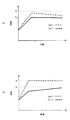
次に、図2を参照し、第1実施形態に係るECU20の動作について説明する。ここに、図2(a)は、エンジン2の出力が大きい場合の、ヒータ入口油温度Toil1及びヒータ温度Twallの推移を示すグラフであって、図2(b)は、エンジン2の出力が小さい場合の、ヒータ入口油温度Toil1及びヒータ温度Twallの推移を示すグラフである。
<Operation of First Embodiment>
Next, the operation of the
図2(a)及び(b)には共通して、横軸に時間がとられ、縦軸に温度がとられている。この縦軸には、ヒータ入口油温度Toil1における、オイルヒータ8への通電の必要性を判定するための上限温度Ta(即ち、本発明に係る「第1所定温度」の一例)、及びヒータ温度Twallにおける、オイルヒータ8への通電の必要性を判定するための上限温度Tb(即ち、本発明に係る「第2所定温度」の一例)が示されている。ヒータ入口油温度Toil1の上限温度Taは、ヒータ温度Twallの上限値Tbより低い温度に設定される。
In FIGS. 2 (a) and 2 (b), time is taken on the horizontal axis and temperature is taken on the vertical axis. The vertical axis indicates an upper limit temperature Ta for determining the necessity of energization of the
図2(a)に示すように、エンジン出力が大きい場合、ヒータ入口油温度Toil1は、比較的大きく上昇し、上限温度Taに達し易い。一方、エンジン出力が大きい場合、ヒータ温度Twallは、上昇しつつも、上限温度Tbに達することがない。これは、オイルヒータ8からオイルへの熱伝導が生じ易く、オイルヒータ8を通過するオイルがオイルヒータ8の熱を多少持ち去るためである。
As shown in FIG. 2A, when the engine output is large, the heater inlet oil temperature Toil1 rises relatively large and easily reaches the upper limit temperature Ta. On the other hand, when the engine output is large, the heater temperature Twall rises but does not reach the upper limit temperature Tb. This is because heat conduction from the
図2(b)に示すように、エンジン出力が小さい場合、ヒータ入口油温度Toil1は、上昇しつつも、上限温度Taに達することがない。一方、エンジン出力が小さい場合、ヒータ温度Twallは、比較的大きく上昇し、上限温度Tbに達し易い。 As shown in FIG. 2B, when the engine output is small, the heater inlet oil temperature Toil1 does not reach the upper limit temperature Ta while increasing. On the other hand, when the engine output is small, the heater temperature Twall rises relatively large and easily reaches the upper limit temperature Tb.
ECU20における通電判定部21は、オイルヒータ8への通電を行うか否かを判定するためのパラメータとして、SOC、ヒータ入口油温度Toil1及びヒータ出口油温度Toil2のうちのいずれか一方(以下、適宜「オイル温度Toilx」と称する)、並びにヒータ温度Twallを用いる。これらパラメータを用いた判定について、具体的には、SOCセンサ11により検出されたSOCが全蓄電量の60パーセントを満たすか否かが判定される。SOCが全蓄電量の60パーセントを満たす場合、オイル温度Toilxが上限温度Taより低いか否かが判定されることで、オイルヒータ8への通電の必要性が判定される。オイル温度Toilxが上限温度Taより低い場合、ヒータ温度Twallが上限温度Tbより低いか否かが判定されることで、オイルヒータ8の故障が回避される。
The
通電判定部21は、SOCが全蓄電量の60パーセントを満たすと判定され、且つオイル温度Toilxが上限温度Taより低いと判定され、且つヒータ温度Twallが上限温度Tbより低いと判定される場合にのみ、オイルヒータ8への通電を行う旨の信号を出力する。
The
ECU20における通電制御部22は、通電判定部21から出力される信号に応じて、スイッチ16の切り替えを行う。具体的には、通電を行う旨の信号が出力された場合、オイルヒータ8に対し所定の通電を行うように、スイッチ16を「ON」状態に切り替える。一方、通電を行う旨の信号が出力されない場合、オイルヒータ8に対し通電不能に、スイッチ16を「OFF」状態に切り替える。ここで、オイルヒータ8に対する「所定の通電」とは、オイル温度Toilxが上限温度Taを超えない程度、且つヒータ温度Twallが上限温度Tbを超えない程度に、例えば比較的高電圧で且つ比較的短時間、バッテリ10の蓄電電力をオイルヒータに供給することを示す。
The
<第1通電制御処理>
本実施形態では、エンジン2を効率的に暖機するべく、ヒータ入口油温度Toil1及びヒータ温度Twallに応じて、オイルヒータ8に対し所定の通電を行うための第1通電制御処理が実行可能である。
<First energization control process>
In the present embodiment, in order to warm up the
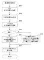
図3を参照し、第1通電制御処理について説明する。ここに、図3は、第1通電制御処理を示すフローチャートである。 The first energization control process will be described with reference to FIG. FIG. 3 is a flowchart showing the first energization control process.
図3において、ECU20は、先ずSOCセンサ11により検出されるSOCが、バッテリ10における全蓄電量の60パーセントより大きいか否かを判定する(ステップS41)。この判定の結果、SOCが全蓄電量の60パーセントより小さいと判定される場合(ステップS41:No)、再度ステップS41の処理を実行する。
In FIG. 3, the
一方、ステップS41の判定の結果、SOCが全蓄電量の60パーセントより大きいと判定される場合(ステップS41:Yes)、通電判定部21は、オイル温度センサ12により検出されるヒータ入口油温度Toil1が上限温度Taより低いか否かを判定する(ステップS42)。この判定の結果、ヒータ入口油温度Toil1が上限温度Taより高いと判定される場合(ステップS42:No)、再度ステップS41の処理を実行する。
On the other hand, as a result of the determination in step S41, when it is determined that the SOC is greater than 60% of the total charged amount (step S41: Yes), the
一方、ステップS42の判定の結果、ヒータ入口油温度Toil1が上限温度Taより低いと判定される場合(ステップS42:Yes)、通電判定部21は、ヒータ温度センサ14により検出されるヒータ温度Twallが上限温度Tbより低いか否かを判定する(ステップS43)。この判定の結果、ヒータ温度Twallが上限温度Tbより高いと判定される場合(ステップS43:No)、再度ステップS41の処理を実行する。
On the other hand, as a result of the determination in step S42, when it is determined that the heater inlet oil temperature Toil1 is lower than the upper limit temperature Ta (step S42: Yes), the
一方、ステップS43の判定の結果、ヒータ温度Twallが上限温度Tbより低いと判定される場合(ステップS43:Yes)、通電制御部22は、オイルヒータ8に対し所定の通電を行うように、スイッチ16を「ON」状態に切り替える(ステップS44)。これにより、一連の第1通電制御処理が終了する。
On the other hand, as a result of the determination in step S43, when it is determined that the heater temperature Twall is lower than the upper limit temperature Tb (step S43: Yes), the
本実施形態の第1通電制御処理によれば、バッテリ10が全蓄電量の60パーセントより大きいSOCを備えており、ヒータ入口油温度Toil1が上限温度Taより低く、且つヒータ温度Twallが上限温度Tbより低い場合、オイルヒータ8に対し所定の通電を行う。これにより、最適な通電タイミングで適当な通電電力をオイルヒータ8に供給するので、オイルヒータ8への通電を的確に行うことが可能である。言い換えれば、オイルヒータ8の稼働効率を高めることが可能である。更には、的確な通電により、オイルの劣化及びオイルヒータ8の故障を抑制することが可能である。
According to the first energization control process of the present embodiment, the
本実施形態では、ECU20により制御される通電の対象は、オイルヒータ8に限られるが、オイルヒータ8に併せてEHCへの通電を制御してもよい。
In the present embodiment, the energization target controlled by the
本実施形態では、ヒータ温度Twallがヒータ温度センサ14により直接に特定されるが、ヒータ温度Twallを特定する形態はこれに限定されない。即ち、ヒータ温度センサ14を用いることなく、ヒータ温度Twallを間接的に特定することも可能である。
In the present embodiment, the heater temperature Twall is directly specified by the
<第1ヒータ温度特定方法>
ヒータ温度センサを用いることなくヒータ温度Twallを特定する、第1の形態では、ヒータ温度Twallの特定に係るパラメータとして、ヒータ入口油温度Toil1及びヒータ出口油温度Toil2、オイル流量m、熱伝達率h、ヒータ面積A並びに比熱Cpが用いられる。ヒータ入口油温度Toil1は、例えばオイル温度センサ12により検出され、ヒータ出口油温度Toil2は、例えばオイル温度センサ13により検出される。オイル流量mは、オイル通路1を構成する複数の部分通路のうち、分岐した部分通路を除いた一部分経路の一断面を単位時間当たりに通過するオイルの質量である。オイル流量mの特定には、例えばエンジン2の回転速度(以後、「機関回転速度」と称する)Ne及びヒータ入口油温度Toil1の関係を表すマップが用いられる。熱伝達率h、ヒータ面積A及び比熱Cpは、オイルヒータ本体の形状、及びオイルの物理的性質から決定される。ここで、数式1は、オイルヒータからオイルへ熱伝達されるエネルギーと、この熱伝達によるオイルの昇温に要するエネルギーとが釣り合うことを表す。ヒータ温度Twallは、数式1から導かれる数式2を用い、上記パラメータに基づいて算出される。
<First heater temperature specifying method>
The heater temperature Twall is specified without using the heater temperature sensor. In the first embodiment, the heater inlet oil temperature Toil1, the heater outlet oil temperature Toil2, the oil flow rate m, and the heat transfer coefficient h are used as parameters related to the specification of the heater temperature Twall. The heater area A and the specific heat Cp are used. The heater inlet oil temperature Toil1 is detected by, for example, the

このように、第1の形態によれば、ヒータ入口油温度Toil1及びヒータ出口油温度Toil2を検出すると共に、新たにオイル流量mを特定することで、ヒータ温度Twallを算出する。これにより、ヒータ温度センサの設置が不要となり、ヒータ温度センサ分のコストを削減することが可能である。 As described above, according to the first embodiment, the heater temperature Twall is calculated by detecting the heater inlet oil temperature Toil1 and the heater outlet oil temperature Toil2 and newly specifying the oil flow rate m. Thereby, installation of a heater temperature sensor becomes unnecessary and it is possible to reduce the cost for the heater temperature sensor.
<第2ヒータ温度特定方法>
ヒータ温度センサを用いることなくヒータ温度Twallを特定する、第2の形態では、ヒータ温度Twallの特定に係るパラメータとして、実抵抗R、基準抵抗R0、基準温度T0及び温度抵抗係数αが用いられる。実抵抗Rは、電流/電圧モニタ15により検出される電流E及び電圧Iに基づいて算出される。基準抵抗R0、基準温度T0及び温度抵抗係数αは、オイルヒータ8において予め設定される。ここで、数式3は、ヒータ温度Twallに応じて変化する実抵抗Rを表す。ヒータ温度Twallは、数式3から導かれる数式4を用い、上記パラメータに基づいて算出される。
<Second heater temperature specifying method>
In the second embodiment in which the heater temperature Twall is specified without using the heater temperature sensor, the actual resistance R, the reference resistance R0, the reference temperature T0, and the temperature resistance coefficient α are used as parameters for specifying the heater temperature Twall. The actual resistance R is calculated based on the current E and voltage I detected by the current /
このように、第2の形態によれば、オイルヒータ8に係る電流E及び電圧Iを検出することで、ヒータ温度Twallを算出する。これにより、第1の形態と同様にして、ヒータ温度センサの設置が不要となり、ヒータ温度センサ分のコストを削減することが可能である。
Thus, according to the second embodiment, the heater temperature Twall is calculated by detecting the current E and the voltage I related to the
<第2実施形態>
<第2実施形態の構成>
次に、図4を参照し、本発明の第2実施形態に係る通信制御システム200の構成について説明する。ここに、図4は、通電制御システム200の構成を概念的に表すブロック図である。尚、通信制御システム200において、図1の通信制御システム100と同一名称且つ同一番号の要素について、その説明を省略する。但し、同一名称であっても異なる番号が付された要素については、図1の通信制御システム100との構成の差異を説明する。
Second Embodiment
<Configuration of Second Embodiment>
Next, the configuration of the communication control system 200 according to the second embodiment of the present invention will be described with reference to FIG. FIG. 4 is a block diagram conceptually showing the configuration of the energization control system 200. In the communication control system 200, description of elements having the same names and the same numbers as those of the communication control system 100 of FIG. 1 is omitted. However, differences in configuration with the communication control system 100 of FIG. 1 will be described for elements having the same name but different numbers.
図4において、通信制御システム200は、主として、エンジン2、オイルヒータ8及びスイッチ16に加えて、EHC30、スイッチ33、バッテリ110及びECU120を備える。
エンジン2における排気ポートには、排気通路29が組み付けられている。エンジン2から排出される排気ガス(排ガス)は、排気通路29に導かれてEHC30に到達する。
In FIG. 4, the communication control system 200 mainly includes an
An
EHC30は、本発明に係る「ヒータ付触媒」の一例であって、排ガスを浄化する不図示の触媒、及び触媒を暖める触媒ヒータ31を備える。
The
触媒ヒータ31の一方の端子には、バッテリ110が接続され、触媒ヒータ31の他方の端子には、スイッチ33が接続されている。スイッチ33は、ECU20によって「ON」及び「OFF」のいずれかの状態をとるように構成されている。スイッチ33が「ON」状態をとる場合、EHC30(言い換えれば、触媒ヒータ31)への通電が継続して行われ、触媒が加熱される。他方、スイッチ33が「OFF」状態をとる場合、EHC30への通電は行われない。EHC30には、触媒温度センサ32が設置されている。
The
触媒温度センサ32は、本発明に係る「第2温度特定手段」の一例であって、触媒の温度(以後、「触媒温度」と称する)Tehcを検出可能に構成されている。触媒温度センサ32は、ECU120と電気的に接続されており、検出された温度Tehcは、ECU120によって一定又は不定の周期で参照される。
The
バッテリ110は、本実施形態においては、オイルヒータ8及びEHC30に対し電力を供給すると共に、不図示のモータジェネレータによる発電電力を蓄電することが可能に構成されている。
In the present embodiment, the
ECU120は、通電制御システム200の各部の動作を制御可能に構成されている。ECU120は、本実施形態においては、ROMに格納された制御プログラムに従って、後述する第2通電制御処理を実行可能に構成されている。
The
尚、ECU120は、本発明に係る「分配比率特定手段」及び「要求電力特定手段」として機能し得る分配比率設定部121と、本発明における第2の車両の通信制御装置に係る「通電制御手段」として機能し得る通電制御部122とを有し、これらの各手段に係る動作は、全てECU120によって実行されるように構成されている。
The
<第2実施形態の動作>
次に、図5から図7を参照し、第2実施形態に係るECU120の動作について説明する。先ず図5を参照し、オイルヒータ8及びEHC30への通電のためにバッテリ110から供給可能である通電電力の合計値たる供給可能電力について説明する。ここに、図5(a)は、SOC及び供給電力の関係を示すグラフであって、図5(b)は、回生電力及び供給電力の関係を示すグラフであって、図5(c)は、バッテリ蓄電電力及び供給可能電力の関係を示すグラフである。
<Operation of Second Embodiment>
Next, the operation of the
図5(a)は、横軸にSOCがとられ、縦軸にSOCに対応する供給電力がとられている。SOCが一定値を満たす場合、SOCの増加に伴って供給電力が増加する。図5(b)は、横軸に回生電力がとられ、縦軸に回生電力に対応する供給電力がとられている。モータジェネレータによる回生電力が零より大きい場合、回生電力の増加に伴って供給電力が増加する。図5(c)は、横軸に、バッテリ蓄電電力として、SOCと回生電力とが合算された電力がとられる。また、縦軸に、供給可能電力として、バッテリ蓄電電力に対応する供給電力がとられている。図5(c)に示すように、供給可能電力とは、バッテリ110のSOCに対応する電力と、モータジェネレータによる発電電力たる回生電力に対応する電力との合計値である。図5を踏まえて、ECU120における分配比率設定部121は、SOCセンサ11により検出されるSOC、及びモータジェネレータによる回生電力を取得し、これらに基づいて供給可能電力を算出する。
In FIG. 5A, the horizontal axis represents the SOC, and the vertical axis represents the supply power corresponding to the SOC. When the SOC satisfies a certain value, the supplied power increases as the SOC increases. In FIG. 5B, the horizontal axis represents regenerative power, and the vertical axis represents supply power corresponding to the regenerative power. When the regenerative power generated by the motor generator is greater than zero, the supplied power increases as the regenerative power increases. In FIG. 5C, the horizontal axis represents electric power obtained by adding SOC and regenerative electric power as battery stored electric power. On the vertical axis, the supply power corresponding to the battery stored power is taken as suppliable power. As shown in FIG. 5C, the suppliable power is a total value of the power corresponding to the SOC of the
続いて、図6を参照し、供給可能電力の分配比率について説明する。ここに、図6は、オイルヒータ8及びEHC30に対し供給される供給可能電力の分配比率の傾向を示すマップである。
Next, the distribution ratio of suppliable power will be described with reference to FIG. FIG. 6 is a map showing the tendency of the distribution ratio of the suppliable power supplied to the
図6は、横軸にEHC温度がとられ、縦軸にオイル温度がとられている。図6に示すように、触媒温度が高く、且つオイル温度が低い程、オイルヒータ8に対する分配比率が高くなる傾向がある。一方、触媒温度が低く、且つオイル温度が高い程、EHC30に対する分配比率が高くなる傾向がある。図6に示される点線は、分配比率が、オイルヒータ8とEHC30との間で逆転する境界を示す。
In FIG. 6, the horizontal axis represents the EHC temperature, and the vertical axis represents the oil temperature. As shown in FIG. 6, as the catalyst temperature is higher and the oil temperature is lower, the distribution ratio to the
続いて、図7を参照し、車速に応じて推移する、供給可能電力の分配比率について説明する。ここに、図7(a)は、車速の推移を示すグラフであって、図7(b)は、車速に応じたオイルヒータ8への供給電力の推移を示すグラフであって、図7(c)は、車速に応じたEHC30への供給電力の推移を示すグラフである。
Next, with reference to FIG. 7, the distribution ratio of the suppliable power that changes according to the vehicle speed will be described. Here, FIG. 7A is a graph showing the transition of the vehicle speed, and FIG. 7B is a graph showing the transition of the power supplied to the
図7(a)は、横軸に時間がとられ、縦軸に車速がとられている。図7(a)に示すように、時間t1から時間t2までの間、車速は一気に増加する。この後、時間t2から時間t3までの間、車速は一定速となる。この後、時間t3から時間t4までの間、車速は一気に減少する。図7(b)は、横軸に時間がとられ、縦軸に車速に応じた、オイルヒータ8への供給電力(以下、適宜「ヒータ供給電力」と称する)がとられている。図7(c)は、横軸に時間がとられ、縦軸に車速に応じた、EHC30への供給電力(以下、適宜「EHC供給電力」と称する)がとられている。尚、本実施形態では、供給可能電力は、ヒータ供給電力及びEHC供給電力として使用されるものとする。
In FIG. 7A, the horizontal axis represents time and the vertical axis represents vehicle speed. As shown in FIG. 7A, the vehicle speed increases at a stretch from time t1 to time t2. Thereafter, the vehicle speed is constant from time t2 to time t3. Thereafter, the vehicle speed decreases at a stretch from time t3 to time t4. In FIG. 7B, time is taken on the horizontal axis, and power supplied to the oil heater 8 (hereinafter referred to as “heater supply power” as appropriate) corresponding to the vehicle speed is taken on the vertical axis. In FIG. 7C, the horizontal axis represents time, and the vertical axis represents power supplied to the
図7(a)から図7(c)に示すように、時間t1から時間t3までの間(即ち、車速が増加する又は一定速となる場合)、オイルヒータ8対EHC30の分配比率は、例えば「3.5」対「1」に設定される。また、時間t3から時間t4までの間(即ち、車速が減少する場合)、オイルヒータ8対EHC30の分配比率は、例えば「1」対「4.6」に設定される。
As shown in FIGS. 7A to 7C, the distribution ratio of the
図6及び図7を踏まえて、ECU120における分配比率設定部121は、本実施形態では、走行状況に応じて、供給可能電力の分配比率を設定する。具体的には、車両が増速する又は一定速で走行する場合、例えば図6等のマップを用いて、オイル温度Toilx及び触媒温度Tehcに基づいて、オイルヒータ8対EHC30の分配比率を一義的に設定する。この際、典型的には、オイルヒータ8及びEHC30のうち、比較的低い温度が検出された一方の分配比率が他方の分配比率より大きくなる。即ち、オイルヒータ8対EHC30の分配比率が例えば「3.5」対「1」に設定される場合、触媒温度Tehcよりオイル温度Toilxについて、比較的低い温度が検出されたこととなる。
Based on FIGS. 6 and 7, the distribution
一方、車両が減速する場合、分配比率設定部121は、先ず触媒温度Tehcに基づいて、EHC30への通電に要求される要求電力Wehcを特定する。すると、分配比率設定部121は、特定した要求電力Wehcと、供給可能電力Wttlから要求電力Wehcを減算した残りの電力Woilとの比率を分配比率として設定する。即ち、オイルヒータ8対EHC30の分配比率が例えば「1」対「4.6」に設定される場合、オイルヒータ8よりEHC30に対する供給電力が優先的に確保されることとなる。
On the other hand, when the vehicle decelerates, the distribution
ECU120における通電制御部122は、本実施形態では、オイルヒータ8及びEHC30に対し、分配比率設定部121により設定された分配比率で供給可能電力が供給されるように、スイッチ16及び33の各々を「ON」状態に切り替える。
In the present embodiment, the
<第2通電制御処理>
本実施形態では、エンジン2及びEHC30を効率的に暖機するべく、オイル温度Toilx及び/又は触媒温度Tehcに基づいて設定される分配比率で、オイルヒータ8及びEHC30に対し電力供給(即ち、通電)を行うための第2通電制御処理が実行可能である。
<Second energization control process>
In the present embodiment, in order to warm up the
図8を参照し、第2通電制御処理について説明する。ここに、図8は、第2通電制御処理を示すフローチャートである。 The second energization control process will be described with reference to FIG. FIG. 8 is a flowchart showing the second energization control process.
図8において、ECU120は、先ずSOCセンサ11により検出されるSOC、及びモータジェネレータによる回生電力を取得する(ステップS51)。すると、分配比率設定部121は、取得されたSOC及び回生電力とに基づいて、バッテリ110における供給可能電力Wttlを算出する(ステップS52)。すると、ECU120は、オイル温度センサ12又は13により検出されるオイル温度Toilx、及び触媒温度センサ32により検出される触媒温度Tehcを取得する(ステップS53)。続いて、ECU120は、車速センサ3により検出される車速から、車両が減速する(或いは減速している)か否かを判定する(ステップS54)。この判定の結果、車両が減速すると判定される場合(ステップS54:Yes)、分配比率設定部121は、触媒温度Tehcに基づいて、EHC30における要求電力Wehcを算出すると共に、ステップS52の処理にて算出された供給可能電力Wttlから、該要求電力Wehcを減算した残りの電力Woilを算出する。こうして算出された、残りの電力Woil対要求電力Wehcの比率を、オイルヒータ8対EHC30の分配比率として設定する(ステップS55)。
In FIG. 8, the
一方、ステップS54の判定の結果、車両が増速する又は一定速で走行すると判定された場合(ステップS54:No)、分配比率設定部121は、オイル温度Toilx及び触媒温度Tehcに基づいて、オイルヒータ8対EHC30の分配比率を一義的に設定する(ステップS56)。
On the other hand, as a result of the determination in step S54, when it is determined that the vehicle speeds up or travels at a constant speed (step S54: No), the distribution
ステップS55又はS56の処理にて分配比率が設定されると、通電制御部122は、設定された分配比率で、オイルヒータ8及びEHC30に対し電力供給を行うように、スイッチ16及び33の各々を「ON」状態に切り替える(ステップS57)。これにより、一連の第2通電制御処理が終了する。
When the distribution ratio is set in the process of step S55 or S56, the
本実施形態の第2通電制御処理によれば、走行状況に応じて、EHC30への通電に要する電力を優先的に確保するように分配比率が特定される。これにより、減速時を利用して、オイルヒータ8よりEHC30を優先する通電を行うことで、触媒を効率的に活性化し、排ガスの浄化作用を高めることが可能である。
According to the second energization control process of the present embodiment, the distribution ratio is specified so as to preferentially secure the power required for energizing the
本発明は、上述した実施形態に限られるものではなく、請求の範囲及び明細書全体から読み取れる発明の要旨或いは思想に反しない範囲で適宜変更可能であり、そのような変更を伴う車両の通電制御装置もまた本発明の技術的範囲に含まれるものである。 The present invention is not limited to the above-described embodiment, and can be appropriately changed without departing from the gist or concept of the invention that can be read from the claims and the entire specification. The apparatus is also included in the technical scope of the present invention.
1…オイル通路、2…エンジン、8…オイルヒータ、12…オイル温度センサ、14…ヒータ温度センサ、20…ECU、100…通電制御システム DESCRIPTION OF SYMBOLS 1 ... Oil passage, 2 ... Engine, 8 ... Oil heater, 12 ... Oil temperature sensor, 14 ... Heater temperature sensor, 20 ... ECU, 100 ... Current supply control system
Claims (7)
前記オイルヒータを通過するオイルの温度たるオイル温度、及び前記オイルヒータ本体の温度たるヒータ温度のうちの少なくとも一方を特定する第1温度特定手段と、
前記蓄電手段の蓄電残量が所定量より大きい場合、前記特定されたオイル温度及びヒータ温度のうちの少なくとも一方に応じて、前記オイルヒータへの通電を行う通電制御手段と
を備えることを特徴とする車両の通電制御装置。 In a vehicle comprising an oil heater provided in a lubrication path in an internal combustion engine and a power storage means capable of energizing the oil heater, an energization control device for controlling energization to the oil heater,
First temperature specifying means for specifying at least one of an oil temperature that is the temperature of oil passing through the oil heater and a heater temperature that is a temperature of the oil heater body;
An energization control unit configured to energize the oil heater according to at least one of the specified oil temperature and heater temperature when the remaining amount of electricity stored in the power storage unit is greater than a predetermined amount. Vehicle energization control device.
前記特定されたヒータ温度が第2所定温度より低いか否かを判定する第2判定手段と
を更に備え、
前記特定されたオイル温度は、前記潤滑経路における前記オイルヒータより上流を通過する前記オイルの温度であって、
前記通電制御手段は、前記第1判定手段により前記オイル温度が前記第1所定温度より低いと判定され、且つ前記第2判定手段により前記ヒータ温度が前記第2所定温度より低いと判定される場合、前記オイルヒータへの通電を行う
ことを特徴とする請求項1に記載の車両の通電制御装置。 First determination means for determining whether the specified oil temperature is lower than a first predetermined temperature;
A second determination means for determining whether or not the specified heater temperature is lower than a second predetermined temperature;
The specified oil temperature is a temperature of the oil passing upstream from the oil heater in the lubrication path,
The energization control unit is configured to determine that the oil temperature is lower than the first predetermined temperature by the first determination unit and that the heater temperature is lower than the second predetermined temperature by the second determination unit. The energization control device for a vehicle according to claim 1, wherein energization of the oil heater is performed.
を更に備え、
前記第1温度特定手段は、前記特定されたオイル温度及びオイル流量に基づいて前記ヒータ温度を特定する
ことを特徴とする請求項1又は2に記載の車両の通電制御装置。 A flow rate specifying means for specifying an oil flow rate as a flow rate of the oil circulating in the lubrication path based on the specified oil temperature and an engine rotation speed in the internal combustion engine;
3. The vehicle energization control device according to claim 1, wherein the first temperature specifying unit specifies the heater temperature based on the specified oil temperature and oil flow rate. 4.
ことを特徴とする請求項1又は2に記載の車両の通電制御装置。 The energization control apparatus for a vehicle according to claim 1 or 2, wherein the first temperature specifying means specifies the heater temperature based on a resistance value of the oil heater.
前記オイルヒータを通過するオイルの温度たるオイル温度、及び前記オイルヒータ本体の温度たるヒータ温度のうちの少なくとも一方を特定する第1温度特定手段と、
前記ヒータ付触媒の温度たる触媒温度を特定する第2温度特定手段と、
前記第1温度特定手段により特定されたオイル温度、及び前記第2温度特定手段により特定された触媒温度のうちの少なくとも一方に基づいて、前記オイルヒータ及び前記ヒータ付触媒に対する、前記蓄電手段における供給可能電力の分配を行うための分配比率を特定する分配比率特定手段と、
前記特定された分配比率で前記分配が行われるように、前記オイルヒータ及び前記ヒータ付触媒への通電を行う通電制御手段と
を備えることを特徴とする車両の通電制御装置。 A vehicle comprising: an oil heater provided in a lubrication path in an internal combustion engine; a catalyst with a heater provided in an exhaust path in the internal combustion engine; and a power storage means capable of energizing at least one of the oil heater and the catalyst with heater In the energization control device for controlling energization to the oil heater and the catalyst with heater,
First temperature specifying means for specifying at least one of an oil temperature that is the temperature of oil passing through the oil heater and a heater temperature that is a temperature of the oil heater body;
Second temperature specifying means for specifying the catalyst temperature as the temperature of the catalyst with heater,
Supply in the power storage means to the oil heater and the catalyst with heater based on at least one of the oil temperature specified by the first temperature specifying means and the catalyst temperature specified by the second temperature specifying means A distribution ratio specifying means for specifying a distribution ratio for distributing possible power;
An energization control device for a vehicle, comprising energization control means for energizing the oil heater and the heater-equipped catalyst so that the distribution is performed at the specified distribution ratio.
を更に備え、
前記分配比率特定手段は、当該車両が減速する場合、(i)前記特定された要求電力と、(ii)前記供給可能電力から前記特定された要求電力を減算した残りの電力との比率を、前記ヒータ付触媒対前記オイルヒータの前記分配比率として特定する
ことを特徴とする請求項5に記載の車両の通電制御装置。 Further comprising required power specifying means for specifying required power required for energizing the catalyst with heater based on the specified catalyst temperature;
When the vehicle decelerates, the distribution ratio specifying means determines the ratio between (i) the specified required power and (ii) the remaining power obtained by subtracting the specified required power from the suppliable power. The vehicle energization control device according to claim 5, wherein the distribution ratio of the heater-equipped catalyst to the oil heater is specified.
ことを特徴とする請求項5又は6に記載の車両の通電制御装置。 The energization control device for a vehicle according to claim 5 or 6, wherein the suppliable power is a value obtained by adding regenerative power output by deceleration of the vehicle to a remaining power storage amount of the power storage means.
Priority Applications (1)
| Application Number | Priority Date | Filing Date | Title |
|---|---|---|---|
| JP2011117353A JP2012246795A (en) | 2011-05-25 | 2011-05-25 | Power supply control device for vehicle |
Applications Claiming Priority (1)
| Application Number | Priority Date | Filing Date | Title |
|---|---|---|---|
| JP2011117353A JP2012246795A (en) | 2011-05-25 | 2011-05-25 | Power supply control device for vehicle |
Publications (1)
| Publication Number | Publication Date |
|---|---|
| JP2012246795A true JP2012246795A (en) | 2012-12-13 |
Family
ID=47467487
Family Applications (1)
| Application Number | Title | Priority Date | Filing Date |
|---|---|---|---|
| JP2011117353A Pending JP2012246795A (en) | 2011-05-25 | 2011-05-25 | Power supply control device for vehicle |
Country Status (1)
| Country | Link |
|---|---|
| JP (1) | JP2012246795A (en) |
Cited By (4)
| Publication number | Priority date | Publication date | Assignee | Title |
|---|---|---|---|---|
| WO2015125505A1 (en) * | 2014-02-20 | 2015-08-27 | 日立オートモティブシステムズ株式会社 | Engine control device |
| WO2017021086A1 (en) * | 2015-07-31 | 2017-02-09 | Continental Automotive Gmbh | Method and device for the treatment of lubricant for an internal combustion engine |
| US10554884B2 (en) | 2012-04-26 | 2020-02-04 | Denso Corporation | In-vehicle camera control device |
| JP2024512461A (en) * | 2021-03-15 | 2024-03-19 | アメリカン アクスル アンド マニュファクチャリング,インコーポレイテッド | Electric drive module configured as a beam axle |
Citations (8)
| Publication number | Priority date | Publication date | Assignee | Title |
|---|---|---|---|---|
| JPS6312813A (en) * | 1986-07-04 | 1988-01-20 | Nippon Soken Inc | Oil supplying system for internal combustion engine |
| JPS63116623A (en) * | 1986-11-06 | 1988-05-20 | 松下電器産業株式会社 | Apparatus for storing perishables |
| JP2003035117A (en) * | 2001-07-24 | 2003-02-07 | Suzuki Motor Corp | Oil cooler |
| JP2005325790A (en) * | 2004-05-17 | 2005-11-24 | Mitsubishi Electric Corp | Engine cooling system control method and engine cooling system control device |
| JP2006174543A (en) * | 2004-12-13 | 2006-06-29 | Honda Motor Co Ltd | Regenerative power control device for hybrid vehicle |
| JP2008114844A (en) * | 2006-11-03 | 2008-05-22 | Ford Global Technologies Llc | Power train for hybrid electric vehicle, and control method therefor |
| JP2008168699A (en) * | 2007-01-10 | 2008-07-24 | Toyota Motor Corp | Control device for hybrid vehicle |
| JP2008195995A (en) * | 2007-02-09 | 2008-08-28 | Matsushita Electric Ind Co Ltd | Vapor growth equipment |
-
2011
- 2011-05-25 JP JP2011117353A patent/JP2012246795A/en active Pending
Patent Citations (8)
| Publication number | Priority date | Publication date | Assignee | Title |
|---|---|---|---|---|
| JPS6312813A (en) * | 1986-07-04 | 1988-01-20 | Nippon Soken Inc | Oil supplying system for internal combustion engine |
| JPS63116623A (en) * | 1986-11-06 | 1988-05-20 | 松下電器産業株式会社 | Apparatus for storing perishables |
| JP2003035117A (en) * | 2001-07-24 | 2003-02-07 | Suzuki Motor Corp | Oil cooler |
| JP2005325790A (en) * | 2004-05-17 | 2005-11-24 | Mitsubishi Electric Corp | Engine cooling system control method and engine cooling system control device |
| JP2006174543A (en) * | 2004-12-13 | 2006-06-29 | Honda Motor Co Ltd | Regenerative power control device for hybrid vehicle |
| JP2008114844A (en) * | 2006-11-03 | 2008-05-22 | Ford Global Technologies Llc | Power train for hybrid electric vehicle, and control method therefor |
| JP2008168699A (en) * | 2007-01-10 | 2008-07-24 | Toyota Motor Corp | Control device for hybrid vehicle |
| JP2008195995A (en) * | 2007-02-09 | 2008-08-28 | Matsushita Electric Ind Co Ltd | Vapor growth equipment |
Cited By (8)
| Publication number | Priority date | Publication date | Assignee | Title |
|---|---|---|---|---|
| US10554884B2 (en) | 2012-04-26 | 2020-02-04 | Denso Corporation | In-vehicle camera control device |
| WO2015125505A1 (en) * | 2014-02-20 | 2015-08-27 | 日立オートモティブシステムズ株式会社 | Engine control device |
| JP2015155651A (en) * | 2014-02-20 | 2015-08-27 | 日立オートモティブシステムズ株式会社 | Control device of engine |
| US10233799B2 (en) | 2014-02-20 | 2019-03-19 | Hitachi Automotive Systems, Ltd. | Engine control device |
| WO2017021086A1 (en) * | 2015-07-31 | 2017-02-09 | Continental Automotive Gmbh | Method and device for the treatment of lubricant for an internal combustion engine |
| JP2024512461A (en) * | 2021-03-15 | 2024-03-19 | アメリカン アクスル アンド マニュファクチャリング,インコーポレイテッド | Electric drive module configured as a beam axle |
| JP7683027B2 (en) | 2021-03-15 | 2025-05-26 | アメリカン アクスル アンド マニュファクチャリング,インコーポレイテッド | Electric drive module configured as a beam axle |
| US12381447B2 (en) | 2021-03-15 | 2025-08-05 | American Axle & Manufacturing, Inc. | Electric drive module configured as a beam axle |
Similar Documents
| Publication | Publication Date | Title |
|---|---|---|
| JP5547699B2 (en) | Vehicle drive device | |
| JP6313455B2 (en) | Hybrid vehicle and air conditioning system thereof | |
| JP5835353B2 (en) | Thermoelectric generator | |
| US20140109872A1 (en) | PHEV Heating Modes to Provide Cabin Comfort | |
| US20090095462A1 (en) | Method and system for controlling cooling fans in a vehicle | |
| CN110198851B (en) | Method for operating a hybrid electric vehicle cooling system including a liquid coolant transfer loop | |
| US8333172B2 (en) | Cooling system | |
| CN102341286A (en) | Hybrid vehicle control device and control method | |
| CN110872969B (en) | Vehicle and control method of vehicle | |
| CN106545401B (en) | System for cooling engine of mild hybrid vehicle and method thereof | |
| JP2014008914A (en) | Control device for hybrid vehicle | |
| US11364771B2 (en) | Control apparatus for hybrid vehicle | |
| CN104723840B (en) | The method for controlling hybrid electric vehicle heating | |
| JP5556901B2 (en) | Vehicle and vehicle control method | |
| JP2012246795A (en) | Power supply control device for vehicle | |
| JP5929678B2 (en) | Control device for hybrid vehicle | |
| JP2009262771A (en) | Hybrid vehicle control device | |
| JP5558697B2 (en) | Motor controller for hybrid vehicle | |
| JP6635066B2 (en) | Hybrid vehicle | |
| JP7126400B2 (en) | Temperature sensor oil immersion determination device and electric motor control device | |
| JP2007245753A (en) | Control device for hybrid vehicle | |
| CN107210704A (en) | Method and apparatus, motor vehicle for running motor | |
| JP6973934B2 (en) | Vehicle heating system | |
| JP6414087B2 (en) | Vehicle air conditioner | |
| CN111824112A (en) | Control device and control method of hybrid vehicle, and storage medium |
Legal Events
| Date | Code | Title | Description |
|---|---|---|---|
| A621 | Written request for application examination |
Free format text: JAPANESE INTERMEDIATE CODE: A621 Effective date: 20130701 |
|
| A131 | Notification of reasons for refusal |
Free format text: JAPANESE INTERMEDIATE CODE: A131 Effective date: 20140507 |
|
| A521 | Written amendment |
Free format text: JAPANESE INTERMEDIATE CODE: A523 Effective date: 20140528 |
|
| A02 | Decision of refusal |
Free format text: JAPANESE INTERMEDIATE CODE: A02 Effective date: 20141028 |