JP2012197948A - Liquefied gas supplying method and controller for liquefied gas supplying system - Google Patents
Liquefied gas supplying method and controller for liquefied gas supplying system Download PDFInfo
- Publication number
- JP2012197948A JP2012197948A JP2012162514A JP2012162514A JP2012197948A JP 2012197948 A JP2012197948 A JP 2012197948A JP 2012162514 A JP2012162514 A JP 2012162514A JP 2012162514 A JP2012162514 A JP 2012162514A JP 2012197948 A JP2012197948 A JP 2012197948A
- Authority
- JP
- Japan
- Prior art keywords
- liquefied gas
- container
- containers
- heating
- temperature
- Prior art date
- Legal status (The legal status is an assumption and is not a legal conclusion. Google has not performed a legal analysis and makes no representation as to the accuracy of the status listed.)
- Granted
Links
Images




Landscapes
- Filling Or Discharging Of Gas Storage Vessels (AREA)
Abstract
【課題】大量の液化ガスを安定供給するため、複数の液化ガス容器内の液化ガスを最後まで均等に供給することができる、液化ガス供給方法を提供する。
【解決手段】複数の液化ガス容器(1)のそれぞれに設置した液化ガス量測定用の検出器(2)からの情報を処理し、該液化ガス容器のそれぞれに設置した加熱装置(3)を制御することによって該複数の液化ガス容器が並列に連結して液化ガスを供給する、液化ガス供給方法であって、
重量測定器である各該検出器(2)からの情報を総合処理して得た数値である前記各容器内の液化ガスの平均重量を基準にして、前記各容器ごとの液化ガス重量と該平均重量との差が所定値以下になるように各該加熱装置(3)を制御することを特徴とする、液化ガス供給方法。
【選択図】図1To provide a liquefied gas supply method capable of uniformly supplying liquefied gas in a plurality of liquefied gas containers to the end in order to stably supply a large amount of liquefied gas.
Information from a liquefied gas amount measurement detector (2) installed in each of a plurality of liquefied gas containers (1) is processed, and a heating device (3) installed in each of the liquefied gas containers is provided. A liquefied gas supply method in which the plurality of liquefied gas containers are connected in parallel by controlling to supply liquefied gas,
Based on the average weight of the liquefied gas in each container, which is a numerical value obtained by comprehensively processing the information from each detector (2) that is a weight measuring device, the weight of the liquefied gas for each container and the A method for supplying a liquefied gas, characterized in that each of the heating devices (3) is controlled such that a difference from an average weight is not more than a predetermined value.
[Selection] Figure 1
Description
本発明は、複数の液化ガス容器の加熱調温による液化ガス供給方法及び液化ガス供給システムの制御装置に関する。 The present invention relates to a liquefied gas supply method by temperature control of a plurality of liquefied gas containers and a control device for a liquefied gas supply system.
常温では蒸気圧が低く蒸発量が少ない液化ガスを大量に消費する場面において、蒸発能力を上げるために、液化ガスの蒸発表面積を増やしたり、液化ガスの温度を上げたり、という方法が取られる。またそれを実現するための手段として、液化ガスの充填容器の胴経を大きくするか標準的なサイズの容器を複数本並列にすること、液化ガスの入っている容器を加熱することがある。そこでそれらを組み合わせた、手軽に入手できる標準的なサイズの容器を複数本並列にし、又は加熱を併用して、蒸発能力を維持しつつ、大量の液化ガスを安定供給できるシステムが検討されてきた。 In a scene where a large amount of liquefied gas having a low vapor pressure and a small amount of evaporation at normal temperature is consumed, a method of increasing the evaporation surface area of the liquefied gas or increasing the temperature of the liquefied gas is taken in order to increase the evaporation capacity. As means for realizing this, there are cases where the length of the liquefied gas filling container is increased or a plurality of containers of standard size are arranged in parallel, and the container containing the liquefied gas is heated. Therefore, a system that can stably supply a large amount of liquefied gas while maintaining the evaporation ability by combining a plurality of easily available standard-sized containers in parallel or by using heating in combination has been studied. .
図7は、従来の液化ガス供給装置の制御方法を示す公知例1の図である(特許文献1)。図7に示すようにこの液化ガス供給装置の制御方法は、複数本の充填容器内の液化ガス(内容物)の残量を、各々に設けられた残量計にて監視しており、各々の残量があらかじめ設定された所定の基準値を下回った容器から、個々に設けられた自動遮断弁が順次閉じていき、吐出を停止していくものである。これによって各容器内の液化ガスの減り方が異なる場合でもすべての容器の液化ガスを最小限の残量まで使い切るようにしたものである。ただし、この公知例1では充填容器内の液化ガスを加熱する手段はない。 FIG. 7 is a diagram of a known example 1 showing a control method of a conventional liquefied gas supply device (Patent Document 1). As shown in FIG. 7, the control method of this liquefied gas supply apparatus monitors the remaining amount of liquefied gas (contents) in a plurality of filled containers with a fuel gauge provided in each, The automatic shut-off valves provided individually are sequentially closed from the containers whose remaining amount is below a predetermined reference value set in advance, and the discharge is stopped. As a result, the liquefied gas in all the containers is used up to the minimum remaining amount even when the liquefied gas in each container is differently reduced. However, in this known example 1, there is no means for heating the liquefied gas in the filling container.
図8は、従来の液化ガス供給システム及び供給方法を示す公知例2の図である(特許文献2)。図8に示すようにこの液化ガス供給システム及び供給方法は、液化ガスを貯蔵する複数の容器とこれらの容器のガス供給管路を介して後流側に設けた圧力調整器の間に貯留部を設けている。容器から常温気化した液化ガスは、供給管路を経て貯留部に蓄えられる。この貯留部は、貯留容積が供給先側の急激な消費量変動に対して対応可能なバッファーとしての容量をもち、ガス供給管路を介して圧力調整器より供給先側へ供給するものである。ただし、この公知例2の場合でも容器内の液化ガスを加熱する手段はない。さらに容器内の液化ガスの残量を検出する手段については対象外としている。 FIG. 8 is a diagram of a known example 2 showing a conventional liquefied gas supply system and supply method (Patent Document 2). As shown in FIG. 8, this liquefied gas supply system and supply method includes a storage section between a plurality of containers for storing liquefied gas and a pressure regulator provided on the downstream side via the gas supply lines of these containers. Is provided. The liquefied gas evaporated at room temperature from the container is stored in the storage section through the supply pipe. This storage unit has a capacity as a buffer whose storage volume can cope with a sudden change in consumption on the supply side, and is supplied from the pressure regulator to the supply side via a gas supply line. . However, even in this known example 2, there is no means for heating the liquefied gas in the container. Further, the means for detecting the remaining amount of liquefied gas in the container is excluded.
図9は、従来の液化ガス供給方法を示す公知例3の図である(特許文献3)。図9に示すようにこの液化ガス供給方法は、液化ガス充填容器100とその供給管路である第1の配管105と第2の配管106、および流量検出手段104を有しており、液化ガス充填容器100と第1の配管105、第2の配管106は、それぞれ第1の加熱手段101から第2の加熱手段102、そして第3の加熱手段103によりその発生熱量を流量検出手段104の計測値に応じて制御し供給するものである。または流量検出手段104の代わりに第2の配管106の後段に設けた複数の分岐バルブ131〜140にて、バルブが開いている数に応じて発生熱量を制御し供給するものである。また、この供給方法には、最低1つ以上の分岐バルブを通過させて常にガスが供給されているという条件下で加熱手段を制御するものになっている。ただし、この公知例3は液化ガス充填容器100が単体であり、複数容器からの同時供給は行っていない。また、液化ガス充填容器100に入っている液化ガスの残量を検出する手段については対象外としている。
FIG. 9 is a diagram of a known example 3 showing a conventional liquefied gas supply method (Patent Document 3). As shown in FIG. 9, this liquefied gas supply method includes a liquefied gas filling container 100, a first pipe 105 and a
図10は、従来の複数容器からなる液化ガス供給システムを示す一般的な従来例4の図である。図10に示すようにこのシステムは、標準的なサイズの容器を複数本並列に接続して、液化ガスの入っている各容器を個々に加熱し、各容器内の液化ガス残量は重量計等の計量器で計測するという従来技術の組み合わせで構成している。なお、加熱源3−1〜3−n、加熱量計測センサー4−1〜4−n、温調器5−1〜5−n、加熱出力器6−1〜6−nの加熱制御系と、計量器2−1〜2−nの容器内液化ガス量の計測系は、各容器ごとに独立している。 FIG. 10 is a diagram of a general conventional example 4 showing a conventional liquefied gas supply system including a plurality of containers. As shown in FIG. 10, this system connects a plurality of containers of standard size in parallel, individually heats each container containing liquefied gas, and the remaining amount of liquefied gas in each container is a weigh scale. It is composed of a combination of conventional techniques of measuring with a measuring instrument such as the above. The heating control system of the heating sources 3-1 to 3-n, the heating amount measuring sensors 4-1 to 4-n, the temperature controllers 5-1 to 5-n, and the heating output devices 6-1 to 6-n The measuring system for the amount of liquefied gas in the containers of the measuring devices 2-1 to 2-n is independent for each container.
図7に示す従来の液化ガス供給装置の制御方法では、もともと特定容器内液化ガス(内容物)2の片減りがあることを前提とし、各々の残量があらかじめ設定された所定の基準値を下回った容器から順次吐出停止となるため、蒸発能力を維持するための条件である蒸発表面積が停止した容器の分だけ少なくなっていき、少量本数では供給能力不足を招くという問題がある。さらに加熱手段をもたないため、常温での蒸発量しかとれないことも供給できる容器本数が少なくなると供給能力不足を加速するという問題もある。 In the conventional control method of the liquefied gas supply device shown in FIG. 7, it is assumed that the liquefied gas (contents) 2 in the specific container is originally reduced, and each remaining amount is set to a predetermined reference value set in advance. Since the discharge is sequentially stopped from the lower container, the evaporation surface area, which is a condition for maintaining the evaporation capacity, decreases by the amount of the stopped container, and there is a problem that the supply capacity is insufficient when the number is small. Furthermore, since there is no heating means, there is a problem that only the amount of evaporation at room temperature can be taken, and if the number of containers that can be supplied decreases, insufficient supply capacity is accelerated.
図8に示す従来の液化ガス供給システムおよび供給方法では、貯留部4という大容量の貯留容積が必要となることや、この貯留部4の温度が大元の容器1の温度より低い場合は、容器1で気化して蓄えられた貯留部4のガスが再液化してしまうという問題がある。言い替えると貯留部4に再液化した状態は、容器1から貯留部4へ移充填したことと同じであり、急激な消費量変動に対して対応可能なバッファーとしての容量をもつ単一大型容器からの供給になってしまう。したがって、貯留部4での再液化防止のためには貯留部4の温度を容器1側より常に高く維持する温度環境を作らなければならないという条件があり、容器1と貯留部4の設置環境に問題が発生する。また、容器1が複数本の場合、容器1それぞれの環境温度が微妙に異なれば容器内部の液化ガス蒸気圧も異なり、圧力の高い容器の液化ガスが先に貯留部4に蓄えられるため、複数容器を同時に交換した場合、公知例1(図7)のような手段がない限り液化ガスの残量が大きくばらつくという問題がある。
In the conventional liquefied gas supply system and supply method shown in FIG. 8, when a large storage volume of the
図9に示す従来の液化ガス供給方法では、供給流量に応じた液化ガスの蒸発熱量を加熱手段101、102、103にて発生するように各加熱手段を制御しているが、加熱手段だけで供給能力を上げるには加熱温度の上限があり、自ずと限界がある。また、この方法で蒸発表面積を増やすために複数本の液化ガス充填容器100を加熱手段101で加熱した場合、個々の容器の加熱手段の制御量は同じであっても実際の液化ガス温度を監視していないため、容器毎に温度差が生じて均等な蒸発量は得られず、加熱温度が高く蒸気圧の高い容器だけが減っていくという片減りの問題がある。 In the conventional liquefied gas supply method shown in FIG. 9, each heating means is controlled so that the heat of evaporation of the liquefied gas corresponding to the supply flow rate is generated by the heating means 101, 102, 103. There is an upper limit of the heating temperature to raise the supply capacity, and there is a limit naturally. Further, when a plurality of liquefied gas filling containers 100 are heated by the heating means 101 in order to increase the evaporation surface area by this method, the actual liquefied gas temperature is monitored even if the control amount of the heating means of each container is the same. Therefore, there is a problem that the temperature difference occurs for each container and a uniform evaporation amount cannot be obtained, and only containers having a high heating temperature and a high vapor pressure are reduced.
図10に示す従来の複数容器からなる液化ガス供給システムでは、各容器を加熱する温調器は容器の表面温度を検知し温度制御を行うものである。しかし、このような制御を行っているにも関わらず、実際には片減りや液化ガスの容器間移動(移充填)してしまうといった問題がある。 In the conventional liquefied gas supply system including a plurality of containers shown in FIG. 10, the temperature controller for heating each container detects the surface temperature of the container and controls the temperature. However, in spite of performing such control, there are actually problems such as partial reduction and movement (transfer filling) of liquefied gas between containers.
発明者らの知見によれば、容器間のごくわずかな温度の違い、例えば容器室内の風の流れの影響によっても液化ガスが容器間を移動(移充填)する。そのため、液化ガスそのものの温度を計測し加熱制御できれば良いのだが、実際には容器内の液化ガスそのものの温度計測が困難なために、実現が困難な状況であった。 According to the knowledge of the inventors, the liquefied gas moves (transfers) between the containers even by a slight temperature difference between the containers, for example, the influence of the wind flow in the container chamber. Therefore, it is only necessary to measure and control the temperature of the liquefied gas itself, but in reality, it is difficult to measure the temperature of the liquefied gas itself in the container.
以上のように従来技術では、液化ガスが入った複数の容器を並列に連結して供給する場合、加熱手段のあるなしを問わずいずれの場合でも容器ごとに異なる微妙な温度差から、供給時には蒸発圧力の高い容器だけ減っていくという片減りが発生すること、そして供給停止時は、容器の連結部を通じて蒸発圧力の高い容器から低い容器へ移充填されるという問題を共通して抱えていた。 As described above, in the prior art, when supplying a plurality of containers containing liquefied gas connected in parallel, the subtle temperature difference that differs from container to container in any case, with or without heating means, There was a common problem that only a container with a high evaporation pressure was reduced, and when the supply was stopped, a container with a high evaporation pressure was transferred from a container with a high evaporation pressure to a low container through the connection part of the container. .
本発明の目的は、大量の液化ガスを安定供給するため、複数の液化ガス容器内の液化ガスを最後まで均等に供給することができる、液化ガス供給システム及び供給方法を提供することである。 An object of the present invention is to provide a liquefied gas supply system and a supply method that can uniformly supply liquefied gas in a plurality of liquefied gas containers to the end in order to stably supply a large amount of liquefied gas.
上記の課題は、あらかじめ定めた数値を基準にして個々の液化ガス容器を調節するのではなく、そのつど全ての容器からの検出情報から得られた数値を基準にして、個々の容器の調節を行うことで解決できる。 The above problem is not to adjust individual liquefied gas containers based on predetermined numerical values, but to adjust individual containers based on numerical values obtained from detection information from all containers each time. It can be solved by doing.
すなわち、第1の視点において、本発明は複数の液化ガス容器と、各容器に設置した液化ガス量測定用の検出器と、各容器に設置した加熱装置と、各検出器からの情報を処理し、各加熱装置を制御する制御装置とを含む液化ガス供給システムであって、制御装置が、各検出器からの情報を総合処理して得た数値を基準にして、各加熱装置を制御することを特徴とする。 That is, in the first aspect, the present invention processes a plurality of liquefied gas containers, a detector for measuring the amount of liquefied gas installed in each container, a heating device installed in each container, and information from each detector. And a liquefied gas supply system including a control device that controls each heating device, and the control device controls each heating device based on numerical values obtained by comprehensively processing information from each detector. It is characterized by that.
液化ガス量の測定項目として、重量測定でも良いし、体積測定でも良い。また、液面高さとして間接的に測定しても良い。測定方法は公知のあらゆる方法が適用可能である。 The measurement item of the amount of liquefied gas may be weight measurement or volume measurement. Moreover, you may measure indirectly as liquid level height. Any known method can be applied as the measurement method.
第2の視点において、本発明に係る液化ガス供給システムは、各検出器が重量測定器であることを特徴とする。 In a second aspect, the liquefied gas supply system according to the present invention is characterized in that each detector is a weight measuring device.
第3の視点において、本発明に係る液化ガス供給システムは、数値が各容器内の液化ガスの平均重量であり、各容器ごとの液化ガス重量と平均重量との差が所定値以下になるように各加熱装置を制御することを特徴とする。 In a third aspect, the liquefied gas supply system according to the present invention is such that the numerical value is an average weight of the liquefied gas in each container, and a difference between the liquefied gas weight and the average weight for each container is equal to or less than a predetermined value. Each of the heating devices is controlled.
第4の視点において、本発明に係る液化ガス供給システムは、各検出器が液化ガスの液面高さ検出器であることを特徴とする。 In a fourth aspect, the liquefied gas supply system according to the present invention is characterized in that each detector is a liquefied gas liquid level detector.
第5の視点において、本発明に係る液化ガス供給システムは、数値が各容器内の液化ガスの平均液面高さであり、各容器ごとの液化ガスの液面高さと平均液面高さとの差が所定値以下になるように各加熱装置を制御することを特徴とする。 In a fifth aspect, in the liquefied gas supply system according to the present invention, the numerical value is the average liquid level of the liquefied gas in each container, and the liquid level of the liquefied gas for each container is equal to the average liquid level. Each heating device is controlled so that the difference becomes a predetermined value or less.
第6の視点において、本発明に係る液化ガス供給システムは、液化ガスの送気側遮断弁と連動して、各容器の連結を遮断する連結遮断弁を有することを特徴とする。 In a sixth aspect, the liquefied gas supply system according to the present invention is characterized by having a connection cutoff valve that cuts off the connection between the containers in conjunction with the liquefied gas supply side cutoff valve.
第7の視点において、本発明は、複数の液化ガス容器のそれぞれに設置した液化ガス量測定用の検出器からの情報を処理し、液化ガス容器のそれぞれに設置した加熱装置を制御することによってガスを供給する、液化ガス供給方法であって、各検出器からの情報を総合処理して得た数値を基準にして、各加熱装置を制御することを特徴とする。 In a seventh aspect, the present invention processes information from a detector for measuring the amount of liquefied gas installed in each of a plurality of liquefied gas containers, and controls a heating device installed in each of the liquefied gas containers. A liquefied gas supply method for supplying gas, characterized in that each heating device is controlled on the basis of numerical values obtained by comprehensively processing information from each detector.
第8の視点において、本発明に係る液化ガス供給方法は、各検出器が、重量測定器及び液面高さ検出器のうちのいずれかであることを特徴とする。 In an eighth aspect, the liquefied gas supply method according to the present invention is characterized in that each detector is one of a weight measuring device and a liquid level detector.
第9の視点において、本発明は、複数の液化ガス容器のそれぞれに設置した液化ガス量測定用の検出器からの情報を処理し、液化ガス容器のそれぞれに設置した加熱装置を制御する、液化ガス供給システムの制御装置であって、各検出器からの情報を総合処理して得た数値を基準にして、各加熱装置を制御することを特徴とする。 In a ninth aspect, the present invention relates to a liquefaction that processes information from a detector for measuring the amount of liquefied gas installed in each of a plurality of liquefied gas containers and controls a heating device installed in each of the liquefied gas containers. A control device for a gas supply system, wherein each heating device is controlled based on a numerical value obtained by comprehensively processing information from each detector.
第10の視点において、本発明に係る液化ガス供給システムの制御装置は、各検出器が、重量測定器及び液面高さ検出器のうちのいずれかであることを特徴とする。 In a tenth aspect, the control device of the liquefied gas supply system according to the present invention is characterized in that each detector is one of a weight measuring device and a liquid level detector.
本発明により、複数の容器に入っている液化ガスは、最後まで均等に減っていく。したがって複数本並列に連結した容器すべてが連結を維持しつつ最後まで均等に蒸発表面積を確保しながら同時に減っていくため、所要の液温度での蒸発能力を供給開始時から終了まで維持することができる。 According to the present invention, the liquefied gas contained in the plurality of containers is uniformly reduced to the end. Therefore, since all the containers connected in parallel maintain the connection and decrease at the same time while ensuring the evaporation surface area evenly, it is possible to maintain the evaporation capacity at the required liquid temperature from the start to the end of the supply. it can.
以下に、本発明に係る液化ガス供給システムと温度制御方法の実施例を図面を参照しながら詳細に説明する。 Embodiments of a liquefied gas supply system and a temperature control method according to the present invention will be described below in detail with reference to the drawings.
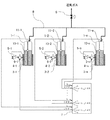
図1は本発明に係る液化ガス供給システムの実施例1の構成を示す図である。図1に示すように本発明の液化ガス供給システムは、複数(n個)の容器1−1〜1−n(1個目の容器を1−1、n個目の容器を1−nのようにサブ符号を付けて表記する。以下同様である。)、計量器2−1〜2−n、加熱源3−1〜3−n、加熱量計測センサー4−1〜4−n、温調器5−1〜5−n、加熱出力器6−1〜6−n、計量値演算比較器7、連結管8、遮断弁9、そして各容器内の液化ガス10−1〜液化ガス10−nで構成される。
FIG. 1 is a diagram showing the configuration of
容器1−1〜1−nは、手軽に入手できる標準的なサイズのものですべて同じ容量のものであり、本供給システムに取り付け前にそれぞれの容器内液化ガス10−1〜10−nの量(本実施例1では重量)が分かっている。各容器1−1〜1−nは、連結管8にて並列接続され、ガスの送気供給ラインにある遮断弁9へと導かれている。
The containers 1-1 to 1-n are of a standard size that can be easily obtained and have the same capacity, and the liquefied gas 10-1 to 10-n in each container is attached before being attached to the supply system. The amount (weight in Example 1) is known. The containers 1-1 to 1-n are connected in parallel by a connecting
この状態にてそれぞれの容器の容器内液化ガスの量(本例では重量)を計量器2−1〜2−nにて常時計測し、その計測値は計量値演算比較器7に送られる。また、各容器には加熱源3−1〜3−n、加熱量計測センサー4−1〜4−nが取り付けられている。事前に得られた当該液化ガスの蒸気圧と温度との相関から導かれる所要の液温度を温調器5−1〜5−nに設定し、計量値演算比較器7が加熱出力器6−1〜6−nを介して加熱源3−1〜3−nにて容器内液化ガス10−1〜10−nの温度をPID制御する。計量値演算比較器7は、取り込まれた計測値を演算し、所定の条件で比較判定して得られた出力信号を温調器5−1〜5−nから出力される制御信号に割り込ませ、加熱出力器6−1〜6−nの出力に補正をかける制御を行う。 In this state, the amount of liquefied gas in each container (weight in this example) is constantly measured by the measuring devices 2-1 to 2 -n, and the measured value is sent to the measured value calculation comparator 7. In addition, heating sources 3-1 to 3-n and heating amount measuring sensors 4-1 to 4-n are attached to each container. The required liquid temperature derived from the correlation between the vapor pressure and temperature of the liquefied gas obtained in advance is set in the temperature controllers 5-1 to 5 -n, and the measured value calculation comparator 7 is used as the heating output device 6-6. The temperature of the liquefied gas 10-1 to 10-n in the container is PID controlled by the heating sources 3-1 to 3-n via 1 to 6-n. The measurement value calculation comparator 7 calculates the acquired measurement value, and interrupts an output signal obtained by comparison and determination under a predetermined condition into a control signal output from the temperature controllers 5-1 to 5-n. Then, control is performed to correct the output of the heating output devices 6-1 to 6-n.
図2〜図4は本発明に係る実施例1の動作を説明する図である。図2〜図4を用いて動作について説明する。 2 to 4 are diagrams for explaining the operation of the first embodiment according to the present invention. The operation will be described with reference to FIGS.
図2は、計量値演算比較器7へ取り込まれる複数(n)の計量器2−1〜2−nの計測値をW−1〜W−n、計量値演算比較器7で演算される全計測値の平均値をWa、計量値演算比較器7のあらかじめ設定した判定値をD、この判定により計量値演算比較器7から出力される停止信号をOFF−1〜OFF−nとして、計量値演算比較器7によって処理される信号を示した図である。 FIG. 2 shows the measured values of the plurality of (n) weighing devices 2-1 to 2-n to be taken into the weighing value calculation comparator 7, W-1 to W-n, and all the values calculated by the weighing value calculation comparator 7. The measurement value is set to Wa, the determination value set in advance of the measurement value calculation comparator 7 as D, and the stop signal output from the measurement value calculation comparator 7 as a result of this determination as OFF-1 to OFF-n. FIG. 6 is a diagram showing signals processed by an arithmetic comparator 7.
また、各温調器5−1〜5−nから出力される制御信号出力をS−1〜S−n、加熱出力器6−1〜6−nから加熱源3−1〜3−nへ最終的に出力される加熱出力をP−1〜P−nとして示した。 Further, control signal outputs outputted from the temperature controllers 5-1 to 5-n are sent from S-1 to Sn, and from the heating output devices 6-1 to 6-n to the heating sources 3-1 to 3-n. The heating output finally outputted is shown as P-1 to P-n.
図3は、本発明における加熱制御のフローチャートである。各温調器5−1〜5−nから加熱出力器6−1〜6−nへ出力される制御信号出力S−1〜S−nに対して、計量値演算比較器7で各計測値W−1〜W−nと平均値Waとの差を演算し、判定値Dと比較することにより判定した結果により停止信号OFF−1〜OFF−nを割り込ませ、加熱源3−1〜3−nの出力P−1〜P−nを制御する一連の処理の流れを示している。 FIG. 3 is a flowchart of the heating control in the present invention. For each of the control signal outputs S-1 to Sn output from the temperature controllers 5-1 to 5-n to the heating output devices 6-1 to 6-n, the measured value calculation comparator 7 measures each measured value. The difference between W-1 to W-n and the average value Wa is calculated, and the stop signal OFF-1 to OFF-n is interrupted according to the determination result by comparing with the determination value D, and the heating sources 3-1 to 3-3. A flow of a series of processes for controlling the outputs P-1 to Pn of -n is shown.
図4は、各温調器5−1〜5−nから加熱出力器6−1〜6−nへ出力される制御信号出力S−1〜S−nと、計量値演算比較器7で演算し判定した結果の停止信号を加熱出力器6−1〜6−nの出力に割り込ませる停止信号OFF−1〜OFF−nと、そして各加熱出力器6−1〜6−nから加熱源3−1〜3−nに最終的に出力される加熱出力P−1〜P−nのON/OFF信号状態の一例を示すタイミングチャートおよびそれに対応する容器内液化ガスの量を示した図である。
FIG. 4 shows the control signal outputs S-1 to Sn output from the temperature controllers 5-1 to 5-n to the heating output devices 6-1 to 6-n and the measurement value calculation comparator 7. Then, the stop signal OFF-1 to OFF-n for interrupting the stop signal as a result of the determination to the outputs of the heating output devices 6-1 to 6-n, and the
従来の方法では、各々の容器は加熱量計測センサー4−1〜4−nで計測した温度が設定温度になるように温調器5−1〜5−nで温度制御するだけであった。言い替えれば、容器個々に独立した温度制御となっており、実際の容器内液化ガスの温度は微妙に差が出るため、液化ガス温度の高い容器から低い容器へ液化ガスが移動(移充填)したり、送気している場合は温度の高い容器の液化ガスだけ減っていくという現象(片減り)が発生する。 In the conventional method, the temperature of each container is only controlled by the temperature controllers 5-1 to 5-n so that the temperature measured by the heating amount measuring sensors 4-1 to 4-n becomes the set temperature. In other words, the temperature control is independent for each container, and the actual temperature of the liquefied gas in the container is slightly different, so the liquefied gas moves (transfers) from a container with a high liquefied gas temperature to a container with a low temperature. In the case of air supply, a phenomenon (decrease) occurs in which only the liquefied gas in the high temperature container is reduced.
これに対し、本発明の実施例1においては、それぞれの容器の容器内液化ガスの重量を計量器2−1〜2−nにて常時計測し、各容器内液化ガス量が総合的に処理されたある量(平均値)に対してあらかじめ設定した判定値(D)以上に少ない容器の加熱を強制的に停止し、蒸発量を抑えている。これをあらかじめ決めた一定間隔で計測比較し、その都度、少ない容器の加熱をその計測比較の間隔で停止するものである。 On the other hand, in Example 1 of this invention, the weight of the liquefied gas in each container is always measured with the measuring devices 2-1 to 2-n, and the amount of liquefied gas in each container is comprehensively processed. The heating of the container, which is smaller than a predetermined determination value (D) with respect to a certain amount (average value), is forcibly stopped to suppress the evaporation amount. This is measured and compared at a predetermined interval, and heating of a small number of containers is stopped at the measurement comparison interval each time.
図4では、容器1−1が最も減り方が多いため、強制加熱停止(OFF−1)が多く働いており、容器1−2は逆に減り方が少なく、強制加熱停止(OFF−2)は働いていない状況を示している。また、容器1−nはわずかに平均値より減った程度であるため、強制加熱停止(OFF−n)の頻度は容器1−1より少ないことを示す。 In FIG. 4, since the container 1-1 has the most reduction method, forced heating stop (OFF-1) works a lot, and the container 1-2 has less reduction method, and the forced heating stop (OFF-2). Indicates a non-working situation. Further, since the container 1-n is slightly reduced from the average value, the frequency of forced heating stop (OFF-n) is less than that of the container 1-1.
前述したように、一定間隔で各容器内液化ガスの量を演算比較し蒸発量が多く平均より少ない量の容器の加熱出力を強制的に停止することにより、一方の容器のみ減少することなく、複数の容器1−1〜1−nに入っている液化ガス10−1〜10−nは、最後まで均等に減っていく。したがって複数本並列に連結した容器すべてが連結を維持しつつ最後まで均等に蒸発表面積を確保しながら同時に減っていくため、所要の液温度での蒸発能力を供給開始時から終了まで維持できる。 As described above, by calculating and comparing the amount of liquefied gas in each container at regular intervals and forcibly stopping the heating output of the container with a large amount of evaporation less than the average, without reducing only one container, The liquefied gas 10-1 to 10-n contained in the plurality of containers 1-1 to 1-n is reduced evenly to the end. Therefore, since all the containers connected in parallel maintain the connection and decrease simultaneously while ensuring the evaporation surface area evenly to the end, the evaporation ability at the required liquid temperature can be maintained from the start to the end of the supply.
本実施例1においては、各容器の容量は同一としているが、必ずしも同一でなくとも良い。ただしその場合、各容器内の液化ガス量の平均値を基準にすることができなくなる。この場合、例えば各容器ごとに容器の全容量と残存液化ガス量との比率を計算し、それを平均して基準値とする等の修正により、実施例1と同様に実施可能である。 In the first embodiment, the capacities of the containers are the same, but they are not necessarily the same. However, in that case, the average value of the amount of liquefied gas in each container cannot be used as a reference. In this case, for example, the ratio between the total capacity of the container and the amount of the remaining liquefied gas is calculated for each container, and it can be carried out in the same manner as in the first embodiment by correcting the average to obtain the reference value.
なお、液化ガスの量として重量ではなく、体積を測定する方法であっても良い。その場合は、実施例1において重量を体積に置き換えて同様に実施可能である。 In addition, the method of measuring the volume instead of the weight as the amount of the liquefied gas may be used. In that case, the embodiment can be similarly implemented by replacing the weight with the volume in the first embodiment.
図5は、本発明に係る液化ガス供給システムの実施例2の構成を示す図である。これは前述した図1における計量器2−1〜2−nの代わりに、容器内の液化ガス残量計測手段として液化ガスの液面レベル(残量)を検知する液面センサー11−1〜11−nを有するものである。また前述した図2における、計量値演算比較器7へ取り込まれる複数(n)の計量器2−1〜2−nの計測値を、液面センサー11−1〜11−nの計測値としてL−1〜L−nに置き替え、計量値演算比較器7で演算される全計測値の平均値をLa、計量値演算比較器7の判定値をD、この判定により計量値演算比較器7から出力される停止信号をOFF−1〜OFF−nとした。なお、図5では液面を検知する例としてフロート式の液面センサーを代表例として図示したが、非接触の超音波式や放射線式の液面センサーを用いてもよい。 FIG. 5 is a diagram showing a configuration of a liquefied gas supply system according to a second embodiment of the present invention. In place of the measuring devices 2-1 to 2-n in FIG. 1 described above, the liquid level sensors 11-1 to 11-1 that detect the liquid level (remaining amount) of the liquefied gas as the liquefied gas remaining amount measuring means in the container. 11-n. Further, in FIG. 2 described above, the measured values of the (n) measuring devices 2-1 to 2-n taken into the measuring value calculation comparator 7 are set as the measured values of the liquid level sensors 11-1 to 11-n. −1 to L−n, the average value of all measurement values calculated by the measurement value calculation comparator 7 is La, the determination value of the measurement value calculation comparator 7 is D, and this determination determines the measurement value calculation comparator 7 The stop signals output from are set to OFF-1 to OFF-n. In FIG. 5, a float type liquid level sensor is shown as a representative example as an example of detecting the liquid level, but a non-contact ultrasonic type or radiation type liquid level sensor may be used.
実施例2を図5を用いて説明する。各容器内液化ガスの量として液面レベルを計量値として連続的に監視し、計量値演算比較器7に取り込む。計量値演算比較器7では、その平均値(La)に対して個々に差(La−(L−1)〜La−(L−n))を計算する。計量値演算比較器7の判定値としてDを、この判定による差がDより大きい場合に計量値演算比較器7から該当する容器の加熱出力器へ停止信号としてOFF−1〜OFF−nが出力される。以下の動作は前述の図3及び図4と同様であり、WaをLaに、W−1をL−1に、W−nをL−nに読み替える。 A second embodiment will be described with reference to FIG. The liquid level is continuously monitored as the measured value as the amount of liquefied gas in each container, and is taken into the measured value calculation comparator 7. The measured value calculation comparator 7 calculates a difference (La− (L−1) to La− (Ln)) individually for the average value (La). D as the determination value of the weighing value calculation comparator 7, and when the difference by this determination is larger than D, OFF-1 to OFF-n are output as stop signals from the weighing value calculation comparator 7 to the heating output device of the corresponding container. Is done. The following operations are the same as those in FIGS. 3 and 4 described above, and Wa is read as La, W-1 is read as L-1, and Wn is read as Ln.
実施例2では、液面センサーによって容器内液化ガスの残量を直接的に計測する。液化ガスの液面レベルを直接的に計測することで実施例1のような重量等を計測する場合と異なり、容器の重量計測に影響する接続配管等の外乱要因が少ない。また、液面レベルを検知しているため、容器胴径や底部形状のばらつきで重量的な残量が異なる場合であっても、液面レベルが容器底部に達するまで均等に減らす制御ができる。 In Example 2, the remaining amount of the liquefied gas in the container is directly measured by the liquid level sensor. Unlike the case of measuring the weight or the like as in the first embodiment by directly measuring the liquid level of the liquefied gas, there are few disturbance factors such as connection pipes that affect the weight measurement of the container. In addition, since the liquid level is detected, even when the remaining weight varies due to variations in the container body diameter and the bottom shape, it is possible to control the liquid level evenly until the liquid level reaches the bottom of the container.
図6は、本発明に係る液化ガス供給システムの実施例3の構成を示す図である。これは、前述した図1に連結遮断弁12−1〜12−nを追加したものである。 FIG. 6 is a diagram illustrating a configuration of a liquefied gas supply system according to a third embodiment of the present invention. This is obtained by adding the connection cutoff valves 12-1 to 12-n to FIG. 1 described above.
以下に実施例3を図6を用いて説明する。通常の供給状態にある場合の動作は前述の図1、図2で説明したとおりであるが、各容器が連結した状態にて、かならずしも供給状態にあり液化ガスが減っていくとは限らず、消費側が停止し送気ガス供給の流れが長期間途絶えている場合や遮断弁9が閉じて待機中の場合もある。
A third embodiment will be described below with reference to FIG. The operation in the normal supply state is as described in FIG. 1 and FIG. 2 described above, but in a state where each container is connected, the liquefied gas is not necessarily reduced in the supply state. There is a case where the consumption side is stopped and the flow of the gas supply gas is interrupted for a long time, or the
この状態では、各容器内の液化ガスはそれぞれの温度で決まる微妙な蒸気圧の違いによって、圧力の高い方から低い方へ互いに容器間を行き来するといった移充填を繰り返し、均等を保っている。特に遮断弁9が閉じており明らかに送気を停止している場合においては、この繰り返し移充填で均等を保つことは不要であり、これを避けるために、連結遮断弁12−1〜12−nは遮断弁9と連動して閉じ、各容器の連結を一時的に遮断するものである。なお、連結遮断時の動作は、強制加熱停止(OFF−1〜OFF−n)は行わず、温調器5−1〜5−nで温度制御するだけである。
In this state, the liquefied gas in each container keeps equality by repeatedly transferring and filling between the containers from the higher pressure side to the lower side due to the subtle difference in vapor pressure determined by the respective temperatures. In particular, when the
実施例3では、特に各容器の液化ガスが満杯状態で待機している時に、万が一にも本発明の均等を保つ演算比較と強制加熱停止機能が作動しなかった場合や加熱源3−1〜3−nが不測に故障した場合など、各容器内の液化ガスはそれぞれの温度で決まる微妙な蒸気圧の違いによって生ずる移充填によって、温度の低い容器の液化ガスがあふれてしまうという危険性があるが、連結遮断弁12−1〜12−nによって各容器の連結を遮断してしまうことにより、安全性が確保できる。 In Example 3, especially when the liquefied gas in each container is waiting in a full state, the operation comparison for maintaining the equality of the present invention and the forced heating stop function do not operate or the heating sources 3-1 to 3-1 There is a risk that the liquefied gas in each container overflows due to transfer and filling caused by a subtle difference in vapor pressure determined by the respective temperatures, such as when 3-n unexpectedly fails. However, safety can be ensured by blocking the connection of the containers by the connection blocking valves 12-1 to 12-n.
以上、本発明を上記実施例に即して説明したが、本発明は上記実施例の構成にのみ制限されるものでなく、本発明の範囲内で当業者であればなし得るであろう各種変形、修正を含むことは勿論である。 Although the present invention has been described with reference to the above-described embodiments, the present invention is not limited to the configurations of the above-described embodiments, and various modifications that can be made by those skilled in the art within the scope of the present invention. Of course, including modifications.
1 (液化ガス)容器
2 計量器
3 加熱源
4 加熱量計測センサー
5 温調器
6 加熱出力器
7 計量値演算比較器
8 連結管
9 遮断弁
10 液化ガス
11 液面センサー
12 連結遮断弁
W 重量の計測値
Wa 重量の計測値の平均値
OFF 停止信号
S 制御信号出力
P 加熱出力
L 液面レベルの計測値
La 液面レベルの計測値の平均値
D 判定値
DESCRIPTION OF SYMBOLS 1 (Liquefied gas)
Claims (2)
重量測定器である各該検出器からの情報を総合処理して得た数値である前記各容器内の液化ガスの平均重量を基準にして、前記各容器ごとの液化ガス重量と該平均重量との差が所定値以下になるように各該加熱装置を制御することを特徴とする、液化ガス供給方法。 The plurality of liquefied gas containers are arranged in parallel by processing information from the detectors for measuring the amount of liquefied gas installed in each of the plurality of liquefied gas containers and controlling a heating device installed in each of the liquefied gas containers. A liquefied gas supply method for connecting and supplying a liquefied gas,
Based on the average weight of the liquefied gas in each container, which is a numerical value obtained by comprehensively processing the information from each detector that is a weight measuring device, the liquefied gas weight for each container and the average weight A method for supplying a liquefied gas, characterized in that each of the heating devices is controlled so that the difference between the two becomes a predetermined value or less.
重量測定器である各該検出器からの情報を総合処理して得た数値である前記各容器内の液化ガスの平均重量を基準にして、前記各容器ごとの液化ガス重量と該平均重量との差が所定値以下になるように各該加熱装置を制御することを特徴とする、液化ガス供給システムの制御装置。 Processing information from a detector for measuring the amount of liquefied gas installed in each of a plurality of liquefied gas containers connected in parallel to supply liquefied gas, and controlling a heating device installed in each of the liquefied gas containers; A control device for a liquefied gas supply system,
Based on the average weight of the liquefied gas in each container, which is a numerical value obtained by comprehensively processing the information from each detector that is a weight measuring device, the liquefied gas weight for each container and the average weight A control device for a liquefied gas supply system, wherein each of the heating devices is controlled so that a difference between the two values becomes a predetermined value or less.
Priority Applications (1)
| Application Number | Priority Date | Filing Date | Title |
|---|---|---|---|
| JP2012162514A JP5414849B2 (en) | 2012-07-23 | 2012-07-23 | LIQUID GAS SUPPLY METHOD AND LIQUID GAS SUPPLY SYSTEM CONTROL DEVICE |
Applications Claiming Priority (1)
| Application Number | Priority Date | Filing Date | Title |
|---|---|---|---|
| JP2012162514A JP5414849B2 (en) | 2012-07-23 | 2012-07-23 | LIQUID GAS SUPPLY METHOD AND LIQUID GAS SUPPLY SYSTEM CONTROL DEVICE |
Related Parent Applications (1)
| Application Number | Title | Priority Date | Filing Date |
|---|---|---|---|
| JP2007131670A Division JP5091539B2 (en) | 2007-05-17 | 2007-05-17 | Liquefied gas supply system |
Publications (2)
| Publication Number | Publication Date |
|---|---|
| JP2012197948A true JP2012197948A (en) | 2012-10-18 |
| JP5414849B2 JP5414849B2 (en) | 2014-02-12 |
Family
ID=47180357
Family Applications (1)
| Application Number | Title | Priority Date | Filing Date |
|---|---|---|---|
| JP2012162514A Active JP5414849B2 (en) | 2012-07-23 | 2012-07-23 | LIQUID GAS SUPPLY METHOD AND LIQUID GAS SUPPLY SYSTEM CONTROL DEVICE |
Country Status (1)
| Country | Link |
|---|---|
| JP (1) | JP5414849B2 (en) |
Cited By (2)
| Publication number | Priority date | Publication date | Assignee | Title |
|---|---|---|---|---|
| JP2015230071A (en) * | 2014-06-05 | 2015-12-21 | 川崎エンジニアリング株式会社 | Hydrogen trailer |
| CN117052569A (en) * | 2022-05-05 | 2023-11-14 | 北汽福田汽车股份有限公司 | LNG gas supply system and control method and vehicle thereof |
Citations (12)
| Publication number | Priority date | Publication date | Assignee | Title |
|---|---|---|---|---|
| JPS5483020U (en) * | 1977-11-25 | 1979-06-12 | ||
| JPH07218317A (en) * | 1994-02-08 | 1995-08-18 | Fujitsu Ltd | Raw material supply device |
| US5454408A (en) * | 1993-08-11 | 1995-10-03 | Thermo Power Corporation | Variable-volume storage and dispensing apparatus for compressed natural gas |
| JPH11165060A (en) * | 1997-09-16 | 1999-06-22 | L'air Liquide | Method for transporting ultrapure gas to point of use and system therefor |
| JPH11226386A (en) * | 1998-02-19 | 1999-08-24 | Nec Yamagata Ltd | Method for controlling gas feed device |
| JP2003028395A (en) * | 2001-07-18 | 2003-01-29 | Hachinohe Ekika Gas Kk | Liquefied gas supplying system and supplying method |
| JP2003269255A (en) * | 2002-03-13 | 2003-09-25 | Honda Motor Co Ltd | Gas fuel supply system for vehicles |
| JP2004116602A (en) * | 2002-09-25 | 2004-04-15 | Honda Motor Co Ltd | Gas remaining amount grasping device |
| JP2004324894A (en) * | 2004-07-29 | 2004-11-18 | Taiyo Nippon Sanso Corp | Gas supply device |
| WO2005010427A1 (en) * | 2003-07-25 | 2005-02-03 | Toyota Jidosha Kabushiki Kaisha | Gas supply system |
| JP2005164044A (en) * | 2003-12-04 | 2005-06-23 | L'air Liquide Sa Pour L'etude & L'exploitation Des Procede S Georges Claude | System for heating tank for liquefied gas by induction |
| JP2006161937A (en) * | 2004-12-07 | 2006-06-22 | Canon Inc | Liquefied gas supply method |
-
2012
- 2012-07-23 JP JP2012162514A patent/JP5414849B2/en active Active
Patent Citations (12)
| Publication number | Priority date | Publication date | Assignee | Title |
|---|---|---|---|---|
| JPS5483020U (en) * | 1977-11-25 | 1979-06-12 | ||
| US5454408A (en) * | 1993-08-11 | 1995-10-03 | Thermo Power Corporation | Variable-volume storage and dispensing apparatus for compressed natural gas |
| JPH07218317A (en) * | 1994-02-08 | 1995-08-18 | Fujitsu Ltd | Raw material supply device |
| JPH11165060A (en) * | 1997-09-16 | 1999-06-22 | L'air Liquide | Method for transporting ultrapure gas to point of use and system therefor |
| JPH11226386A (en) * | 1998-02-19 | 1999-08-24 | Nec Yamagata Ltd | Method for controlling gas feed device |
| JP2003028395A (en) * | 2001-07-18 | 2003-01-29 | Hachinohe Ekika Gas Kk | Liquefied gas supplying system and supplying method |
| JP2003269255A (en) * | 2002-03-13 | 2003-09-25 | Honda Motor Co Ltd | Gas fuel supply system for vehicles |
| JP2004116602A (en) * | 2002-09-25 | 2004-04-15 | Honda Motor Co Ltd | Gas remaining amount grasping device |
| WO2005010427A1 (en) * | 2003-07-25 | 2005-02-03 | Toyota Jidosha Kabushiki Kaisha | Gas supply system |
| JP2005164044A (en) * | 2003-12-04 | 2005-06-23 | L'air Liquide Sa Pour L'etude & L'exploitation Des Procede S Georges Claude | System for heating tank for liquefied gas by induction |
| JP2004324894A (en) * | 2004-07-29 | 2004-11-18 | Taiyo Nippon Sanso Corp | Gas supply device |
| JP2006161937A (en) * | 2004-12-07 | 2006-06-22 | Canon Inc | Liquefied gas supply method |
Cited By (2)
| Publication number | Priority date | Publication date | Assignee | Title |
|---|---|---|---|---|
| JP2015230071A (en) * | 2014-06-05 | 2015-12-21 | 川崎エンジニアリング株式会社 | Hydrogen trailer |
| CN117052569A (en) * | 2022-05-05 | 2023-11-14 | 北汽福田汽车股份有限公司 | LNG gas supply system and control method and vehicle thereof |
Also Published As
| Publication number | Publication date |
|---|---|
| JP5414849B2 (en) | 2014-02-12 |
Similar Documents
| Publication | Publication Date | Title |
|---|---|---|
| JP5091539B2 (en) | Liquefied gas supply system | |
| KR100982683B1 (en) | Precise and reliable water level control method of pressure tank including a plurality of sensors | |
| CN101517495B (en) | Multi-mode control algorithm | |
| KR101437151B1 (en) | Gas supply control system and Method thereof | |
| JP6784711B2 (en) | Liquefied gas supply device and liquefied gas supply method | |
| CA2879065A1 (en) | Boiler system | |
| JP4795825B2 (en) | Gas supply apparatus and gas supply method | |
| JP2013527077A (en) | Refueling apparatus and method for refueling an aircraft tank system | |
| JP5414849B2 (en) | LIQUID GAS SUPPLY METHOD AND LIQUID GAS SUPPLY SYSTEM CONTROL DEVICE | |
| US20170030972A1 (en) | Actuator fault detection device, controlling device and control method | |
| CN104989952A (en) | Continuous and stable high-purity chemical conveying system and method | |
| AU2015288424B2 (en) | Device and method for monitoring of annulus volume in a pipe | |
| JP2014129897A (en) | Heat supply control device, heat supply system and heat supply control method | |
| JP4950518B2 (en) | Gas supply method and gas supply apparatus | |
| JP6695194B2 (en) | Fuel gas filling system and fuel gas filling method | |
| JP5111962B2 (en) | Liquefied gas supply method and apparatus | |
| JP6122231B1 (en) | Liquefied gas supply method | |
| JP2014152869A (en) | Liquefied gas supply device and method | |
| KR101263240B1 (en) | A error adjusting device using a integration calorimeter and method thereof | |
| TWI530639B (en) | Liquefied gas supply device and method | |
| KR20140135717A (en) | Evaluation device and computer program | |
| US20140358300A1 (en) | Portable Control System for Cylinder Cabinet | |
| KR101090738B1 (en) | Control device that supply gas of gas supply system and control method thereof | |
| KR102913807B1 (en) | Gas distribution device capable of controlling supply line pressure and flow rate and integrated control system using the same | |
| JP2006107972A (en) | Gas supply apparatus and method |
Legal Events
| Date | Code | Title | Description |
|---|---|---|---|
| A621 | Written request for application examination |
Free format text: JAPANESE INTERMEDIATE CODE: A621 Effective date: 20120723 |
|
| TRDD | Decision of grant or rejection written | ||
| A01 | Written decision to grant a patent or to grant a registration (utility model) |
Free format text: JAPANESE INTERMEDIATE CODE: A01 Effective date: 20131029 |
|
| A61 | First payment of annual fees (during grant procedure) |
Free format text: JAPANESE INTERMEDIATE CODE: A61 Effective date: 20131112 |
|
| R150 | Certificate of patent or registration of utility model |
Ref document number: 5414849 Country of ref document: JP Free format text: JAPANESE INTERMEDIATE CODE: R150 |
|
| S531 | Written request for registration of change of domicile |
Free format text: JAPANESE INTERMEDIATE CODE: R313531 |
|
| R350 | Written notification of registration of transfer |
Free format text: JAPANESE INTERMEDIATE CODE: R350 |