JP2012095700A - Vacuum cleaner - Google Patents

Vacuum cleaner Download PDF

Info

Publication number
JP2012095700A
JP2012095700A JP2010243615A JP2010243615A JP2012095700A JP 2012095700 A JP2012095700 A JP 2012095700A JP 2010243615 A JP2010243615 A JP 2010243615A JP 2010243615 A JP2010243615 A JP 2010243615A JP 2012095700 A JP2012095700 A JP 2012095700A
Authority
JP
Japan
Prior art keywords
electric blower
dust
vacuum cleaner
input
electric
Prior art date
Legal status (The legal status is an assumption and is not a legal conclusion. Google has not performed a legal analysis and makes no representation as to the accuracy of the status listed.)
Granted
Application number
JP2010243615A
Other languages
Japanese (ja)
Other versions
JP5916990B2 (en
Inventor
Masamichi Une
正道 宇根
Current Assignee (The listed assignees may be inaccurate. Google has not performed a legal analysis and makes no representation or warranty as to the accuracy of the list.)
Toshiba Corp
Toshiba Lifestyle Products and Services Corp
Original Assignee
Toshiba Corp
Toshiba Consumer Electronics Holdings Corp
Toshiba Home Appliances Corp
Priority date (The priority date is an assumption and is not a legal conclusion. Google has not performed a legal analysis and makes no representation as to the accuracy of the date listed.)
Filing date
Publication date
Application filed by Toshiba Corp, Toshiba Consumer Electronics Holdings Corp, Toshiba Home Appliances Corp filed Critical Toshiba Corp
Priority to JP2010243615A priority Critical patent/JP5916990B2/en
Priority to CN201110331381.8A priority patent/CN102462452B/en
Priority to RU2011143900/12A priority patent/RU2486858C1/en
Priority to KR1020110111485A priority patent/KR101411028B1/en
Publication of JP2012095700A publication Critical patent/JP2012095700A/en
Application granted granted Critical
Publication of JP5916990B2 publication Critical patent/JP5916990B2/en
Expired - Fee Related legal-status Critical Current
Anticipated expiration legal-status Critical

Links

Images

Classifications

    • AHUMAN NECESSITIES
    • A47FURNITURE; DOMESTIC ARTICLES OR APPLIANCES; COFFEE MILLS; SPICE MILLS; SUCTION CLEANERS IN GENERAL
    • A47LDOMESTIC WASHING OR CLEANING; SUCTION CLEANERS IN GENERAL
    • A47L9/00Details or accessories of suction cleaners, e.g. mechanical means for controlling the suction or for effecting pulsating action; Storing devices specially adapted to suction cleaners or parts thereof; Carrying-vehicles specially adapted for suction cleaners
    • A47L9/28Installation of the electric equipment, e.g. adaptation or attachment to the suction cleaner; Controlling suction cleaners by electric means
    • A47L9/2805Parameters or conditions being sensed
    • A47L9/281Parameters or conditions being sensed the amount or condition of incoming dirt or dust
    • A47L9/2815Parameters or conditions being sensed the amount or condition of incoming dirt or dust using optical detectors
    • AHUMAN NECESSITIES
    • A47FURNITURE; DOMESTIC ARTICLES OR APPLIANCES; COFFEE MILLS; SPICE MILLS; SUCTION CLEANERS IN GENERAL
    • A47LDOMESTIC WASHING OR CLEANING; SUCTION CLEANERS IN GENERAL
    • A47L5/00Structural features of suction cleaners
    • A47L5/12Structural features of suction cleaners with power-driven air-pumps or air-compressors, e.g. driven by motor vehicle engine vacuum
    • A47L5/22Structural features of suction cleaners with power-driven air-pumps or air-compressors, e.g. driven by motor vehicle engine vacuum with rotary fans
    • A47L5/36Suction cleaners with hose between nozzle and casing; Suction cleaners for fixing on staircases; Suction cleaners for carrying on the back
    • A47L5/362Suction cleaners with hose between nozzle and casing; Suction cleaners for fixing on staircases; Suction cleaners for carrying on the back of the horizontal type, e.g. canister or sledge type
    • AHUMAN NECESSITIES
    • A47FURNITURE; DOMESTIC ARTICLES OR APPLIANCES; COFFEE MILLS; SPICE MILLS; SUCTION CLEANERS IN GENERAL
    • A47LDOMESTIC WASHING OR CLEANING; SUCTION CLEANERS IN GENERAL
    • A47L9/00Details or accessories of suction cleaners, e.g. mechanical means for controlling the suction or for effecting pulsating action; Storing devices specially adapted to suction cleaners or parts thereof; Carrying-vehicles specially adapted for suction cleaners
    • A47L9/24Hoses or pipes; Hose or pipe couplings
    • A47L9/248Parts, details or accessories of hoses or pipes
    • AHUMAN NECESSITIES
    • A47FURNITURE; DOMESTIC ARTICLES OR APPLIANCES; COFFEE MILLS; SPICE MILLS; SUCTION CLEANERS IN GENERAL
    • A47LDOMESTIC WASHING OR CLEANING; SUCTION CLEANERS IN GENERAL
    • A47L9/00Details or accessories of suction cleaners, e.g. mechanical means for controlling the suction or for effecting pulsating action; Storing devices specially adapted to suction cleaners or parts thereof; Carrying-vehicles specially adapted for suction cleaners
    • A47L9/28Installation of the electric equipment, e.g. adaptation or attachment to the suction cleaner; Controlling suction cleaners by electric means
    • A47L9/2836Installation of the electric equipment, e.g. adaptation or attachment to the suction cleaner; Controlling suction cleaners by electric means characterised by the parts which are controlled
    • A47L9/2842Suction motors or blowers
    • AHUMAN NECESSITIES
    • A47FURNITURE; DOMESTIC ARTICLES OR APPLIANCES; COFFEE MILLS; SPICE MILLS; SUCTION CLEANERS IN GENERAL
    • A47LDOMESTIC WASHING OR CLEANING; SUCTION CLEANERS IN GENERAL
    • A47L9/00Details or accessories of suction cleaners, e.g. mechanical means for controlling the suction or for effecting pulsating action; Storing devices specially adapted to suction cleaners or parts thereof; Carrying-vehicles specially adapted for suction cleaners
    • A47L9/32Handles
    • A47L9/327Handles for suction cleaners with hose between nozzle and casing

Landscapes

  • Engineering & Computer Science (AREA)
  • Mechanical Engineering (AREA)
  • Electric Vacuum Cleaner (AREA)

Abstract

【課題】掃除状態に適した電力で掃除できる電気掃除機を提供する。
【解決手段】電気掃除機は、電動送風機18を収容した掃除機本体を有する。電気掃除機は、電動送風機18の吸込側に連通する風路を有する。電気掃除機は、風路を通過する塵埃量を検出する光センサ33を有する。電気掃除機は、把持操作用の手元操作部を有する。電気掃除機は、手元操作部の動作を検知する動作検出手段45を有する。電気掃除機は、光センサ33により検出した塵埃量、および、動作検出手段45により検出した動作に基づいて電動送風機18の駆動を制御する制御手段37を有する。
【選択図】図1
An electric vacuum cleaner capable of cleaning with electric power suitable for a cleaning state is provided.
The vacuum cleaner has a vacuum cleaner body in which an electric blower 18 is housed. The vacuum cleaner has an air passage communicating with the suction side of the electric blower 18. The vacuum cleaner has an optical sensor 33 that detects the amount of dust passing through the air passage. The vacuum cleaner has a hand operating unit for gripping operation. The electric vacuum cleaner has an operation detection means 45 for detecting the operation of the hand operation unit. The electric vacuum cleaner has a control unit 37 that controls the driving of the electric blower 18 based on the amount of dust detected by the optical sensor 33 and the operation detected by the operation detection unit 45.
[Selection] Figure 1

Description

本発明の実施形態は、電動送風機の吸込側に連通する風路を通過する塵埃量を検出する塵埃量検出手段を備えた電気掃除機に関する。   The embodiment of the present invention relates to a vacuum cleaner provided with dust amount detection means for detecting the amount of dust passing through an air passage communicating with the suction side of an electric blower.

従来、例えばキャニスタ型の電気掃除機は、電動送風機を収容した本体ケースを有する掃除機本体を備えている。この掃除機本体には、電動送風機の吸込側に連通する集塵部が配置されており、この集塵部には、電動送風機の吸込側に連通する風路を内部に区画する風路形成体が接続される。この風路形成体は、基端側から先端側へと、ホース体、延長管および床ブラシが順次連通接続されて構成される。そして、風路の内部には、この風路の内部を通過する塵埃量を検出する塵埃量検出手段としての光センサが配置されており、この光センサにより検出した塵埃量に対応して、電動送風機、あるいは床ブラシに配置された電動機などの入力を制御するように構成されている。   2. Description of the Related Art Conventionally, for example, a canister type vacuum cleaner includes a vacuum cleaner body having a body case that houses an electric blower. The vacuum cleaner main body is provided with a dust collecting portion communicating with the suction side of the electric blower, and the dust collecting portion includes an air passage forming body that divides an air passage communicating with the suction side of the electric blower inside. Is connected. The air path forming body is configured by sequentially connecting a hose body, an extension pipe, and a floor brush from the proximal end side to the distal end side. An optical sensor as a dust amount detecting means for detecting the amount of dust passing through the inside of the air passage is disposed inside the air passage, and electric motors are provided corresponding to the dust amount detected by the optical sensor. It is comprised so that input, such as an electric motor arrange | positioned at an air blower or a floor brush, may be controlled.

特開昭59−118126号公報JP 59-118126 A 特開平02−307420号公報Japanese Patent Laid-Open No. 02-307420

電気掃除機においては、塵埃量検出手段により検出した塵埃量だけでなく、例えば使用者がどのように電気掃除機を動作させているかなどの掃除状態によっても、要求される電動送風機の入力が異なるため、掃除状態に適した入力に設定することが望まれる。   In a vacuum cleaner, not only the amount of dust detected by the dust amount detection means but also the required input of the electric blower differs depending on the cleaning state such as how the user operates the vacuum cleaner, for example. Therefore, it is desired to set the input suitable for the cleaning state.

本発明は、このような点に鑑みなされたもので、掃除状態に適した電力で掃除できる電気掃除機を提供することを目的とする。   This invention is made | formed in view of such a point, and it aims at providing the vacuum cleaner which can be cleaned with the electric power suitable for the cleaning state.

実施形態の電気掃除機は、電動送風機を収容した掃除機本体を有する。この電気掃除機は、電動送風機の吸込側に連通する風路を有する。また、この電気掃除機は、風路を通過する塵埃量を検出する塵埃量検出手段を有する。さらに、この電気掃除機は、把持操作される手元操作部を有する。また、この電気掃除機は、手元操作部の動作を検知する動作検出手段を有する。そして、この電気掃除機は、塵埃量検出手段により検出した塵埃量、および、動作検出手段により検出した手元操作部の動作に基づいて電動送風機の駆動を制御する制御手段を有する。   The vacuum cleaner of the embodiment has a vacuum cleaner body that houses an electric blower. The vacuum cleaner has an air passage communicating with the suction side of the electric blower. In addition, this vacuum cleaner has a dust amount detection means for detecting the amount of dust passing through the air passage. Further, the electric vacuum cleaner has a hand operation unit that is gripped. Moreover, this vacuum cleaner has an operation | movement detection means which detects operation | movement of a hand operation part. The vacuum cleaner has control means for controlling the driving of the electric blower based on the amount of dust detected by the dust amount detection means and the operation of the hand operation unit detected by the operation detection means.

第1の実施形態の電気掃除機の内部構造を示すブロック図である。It is a block diagram which shows the internal structure of the vacuum cleaner of 1st Embodiment. 同上電気掃除機の一部を示す縦断面図である。It is a longitudinal cross-sectional view which shows a part of vacuum cleaner same as the above. 同上電気掃除機を示す斜視図である。It is a perspective view which shows a vacuum cleaner same as the above. 同上電気掃除機の制御を示すマトリクスである。It is a matrix which shows control of a vacuum cleaner same as the above. 同上電気掃除機の制御を示すフローチャートである。It is a flowchart which shows control of a vacuum cleaner same as the above. 第2の実施形態の電気掃除機の内部構造を示すブロック図である。It is a block diagram which shows the internal structure of the vacuum cleaner of 2nd Embodiment. 同上電気掃除機を示す斜視図である。It is a perspective view which shows a vacuum cleaner same as the above. 同上電気掃除機の制御を示すマトリクスである。It is a matrix which shows control of a vacuum cleaner same as the above. 同上電気掃除機の制御を示すフローチャートである。It is a flowchart which shows control of a vacuum cleaner same as the above. 第3の実施形態の電気掃除機の内部構造を示すブロック図である。It is a block diagram which shows the internal structure of the vacuum cleaner of 3rd Embodiment. 同上電気掃除機の吸込口体の一部を示す平面図である。It is a top view which shows a part of suction inlet body of a vacuum cleaner same as the above. 同上電気掃除機の制御を示すマトリクスである。It is a matrix which shows control of a vacuum cleaner same as the above. 同上電気掃除機の制御を示すフローチャートである。It is a flowchart which shows control of a vacuum cleaner same as the above. 第4の実施形態の電気掃除機の内部構造を示すブロック図である。It is a block diagram which shows the internal structure of the vacuum cleaner of 4th Embodiment. 同上電気掃除機の制御を示すマトリクスである。It is a matrix which shows control of a vacuum cleaner same as the above. 同上電気掃除機の制御を示すフローチャートである。It is a flowchart which shows control of a vacuum cleaner same as the above. 第5の実施形態の電気掃除機の制御を示すマトリクスである。It is a matrix which shows control of the vacuum cleaner of 5th Embodiment. 同上電気掃除機の制御を示すフローチャートである。It is a flowchart which shows control of a vacuum cleaner same as the above. 第6の実施形態の電気掃除機の制御を示すマトリクスである。It is a matrix which shows control of the vacuum cleaner of 6th Embodiment. 同上電気掃除機の制御を示すフローチャートである。It is a flowchart which shows control of a vacuum cleaner same as the above.

以下、第1の実施形態の構成を、図面を参照して説明する。   The configuration of the first embodiment will be described below with reference to the drawings.

図3において、11はいわゆるキャニスタ型の電気掃除機を示し、この電気掃除機11は、掃除機本体12と、この掃除機本体12に着脱可能に接続される管部である風路形成体13とを有している。   In FIG. 3, reference numeral 11 denotes a so-called canister-type vacuum cleaner. The vacuum cleaner 11 includes a vacuum cleaner body 12 and an air passage forming body 13 which is a pipe portion detachably connected to the cleaner body 12. And have.

掃除機本体12は、被掃除面上を旋回および走行可能な中空状の本体ケース15を備えており、この本体ケース15の内部に、図示しない本体集塵室と電動送風機室とが前後に区画されている。さらに、電動送風機室には、電動送風機18が収容されており、この電動送風機18の吸込側が本体集塵室に連通している。また、本体集塵室内には、フィルタ、集塵袋、あるいは集塵装置(集塵カップ)などの集塵部が配置されている。そして、本体ケース15の前部には、本体集塵室に連通するとともに風路形成体13の基端側が接続される本体吸込口19が開口形成されている。   The vacuum cleaner main body 12 includes a hollow main body case 15 that can swivel and run on the surface to be cleaned, and a main body dust collection chamber and an electric blower chamber (not shown) are partitioned in the front and rear in the main body case 15. Has been. Furthermore, an electric blower 18 is accommodated in the electric blower chamber, and the suction side of the electric blower 18 communicates with the main body dust collection chamber. Further, a dust collecting section such as a filter, a dust collecting bag, or a dust collecting device (dust collecting cup) is disposed in the main body dust collecting chamber. A main body suction port 19 is formed in the front portion of the main body case 15 so as to communicate with the main body dust collection chamber and to which the proximal end side of the air passage forming body 13 is connected.

また、風路形成体13は、長尺状のホース体21と、このホース体21に着脱可能に接続される延長管22と、この延長管22に着脱可能に接続される吸込口体としての床ブラシ23とを備えており、電動送風機18の吸込側に連通する風路Wを内部に形成している。なお、この風路形成体13は、例えば床ブラシ23を取り外して使用することもできるし、床ブラシ23および延長管22を取り外して使用することもできる。   The air passage forming body 13 includes a long hose body 21, an extension pipe 22 that is detachably connected to the hose body 21, and a suction port body that is detachably connected to the extension pipe 22. A floor brush 23 is provided, and an air passage W communicating with the suction side of the electric blower 18 is formed inside. The air path forming body 13 can be used with the floor brush 23 removed, for example, or the floor brush 23 and the extension pipe 22 can be removed.

ホース体21は、長尺筒状のホース本体25と、このホース本体25の一端側である基端側(下流端側)に連通して形成された接続管部26と、ホース本体25の他端側である先端側(上流端側)に連通して形成され例えば風路形成体13の把持操作用の手元操作部27とを一体的に有している。   The hose body 21 includes a long cylindrical hose body 25, a connecting pipe portion 26 formed in communication with the base end side (downstream end side) which is one end side of the hose body 25, For example, a hand operating part 27 for gripping operation of the air passage forming body 13 is formed integrally with the front end side (upstream end side) which is the end side.

ホース本体25は、可撓性を有する合成樹脂などにより円筒蛇腹状に形成されており、手元操作部27側と掃除機本体12側とを電気的に接続する図示しない配線が内部でかつ風路Wの外部に螺旋状に取り付けられている。   The hose body 25 is formed in a cylindrical bellows shape using a flexible synthetic resin or the like, and a wiring (not shown) that electrically connects the hand operating section 27 side and the cleaner body 12 side is provided inside and the air passage. It is attached to the outside of W in a spiral shape.

接続管部26は、本体吸込口19に挿入接続される部分であり、ホース本体25よりも硬質の合成樹脂などにより円筒状に形成されている。また、この接続管部26には、ホース本体25内に配置された配線と電気的に接続された図示しない端子が配置されており、これら端子が、接続管部26を本体吸込口19に挿入接続することで掃除機本体12側と電気的に接続される。そして、接続管部26が接続される本体吸込口19の内部には、図2に示すように、風路Wを通過する塵埃量を検出するための塵埃量検出手段としての光センサ33が配置されている。   The connecting pipe portion 26 is a portion that is inserted and connected to the main body suction port 19 and is formed in a cylindrical shape from a synthetic resin harder than the hose main body 25. In addition, a terminal (not shown) that is electrically connected to the wiring disposed in the hose body 25 is disposed in the connecting pipe part 26, and these terminals insert the connecting pipe part 26 into the main body suction port 19. By connecting, it is electrically connected to the cleaner body 12 side. An optical sensor 33 as a dust amount detecting means for detecting the amount of dust passing through the air passage W is disposed inside the main body suction port 19 to which the connecting pipe portion 26 is connected, as shown in FIG. Has been.

ここで、光センサ33は、図1および図2に示すように、例えば赤外光を発光する発光手段としての発光部35と、この発光部35により発光された赤外光を受光する受光手段としての受光部36とを互いに対向する位置に備えており、発光部35からの赤外光の受光部36での受光量によって、風路W中を通過する塵埃量に対応する信号を制御手段37に出力可能となっている。   Here, as shown in FIGS. 1 and 2, the optical sensor 33 includes, for example, a light emitting unit 35 as a light emitting unit that emits infrared light, and a light receiving unit that receives the infrared light emitted by the light emitting unit 35. The light receiving unit 36 is provided at a position facing each other, and a signal corresponding to the amount of dust passing through the air passage W is controlled by the amount of infrared light received by the light receiving unit 36 from the light emitting unit 35. Output to 37 is possible.

発光部35は、赤外光などの光を出力するLEDなどの発光素子35aと、この発光素子35aからの発光を風路W内へと導く発光側導光部材としての一方および他方の発光側レンズ35b,35cとを有している。   The light emitting unit 35 includes a light emitting element 35a such as an LED that outputs light such as infrared light, and one and the other light emitting side as a light emitting side light guide member that guides light emitted from the light emitting element 35a into the air path W. Lenses 35b and 35c.

発光素子35aは、例えば掃除機本体12の本体吸込口19の上部に、下方に向けて配置されており、この下方へと赤外光を出力するように構成されている。また、この発光素子35aは、アノード側が可変抵抗器などの抵抗器R1を介して電源部38に電気的に接続され、カソード側が接地されている。   The light emitting element 35a is disposed, for example, at the upper part of the main body suction port 19 of the cleaner body 12, and is configured to output infrared light downward. The light emitting element 35a has an anode side electrically connected to the power supply unit 38 via a resistor R1 such as a variable resistor, and a cathode side grounded.

また、一方の発光側レンズ35bは、発光素子35aの赤外光の出力側である下方にて本体吸込口19の内面に配置されている。   One light-emitting side lens 35b is disposed on the inner surface of the main body suction port 19 below the infrared light output side of the light-emitting element 35a.

また、他方の発光側レンズ35cは、風路形成体13の接続管部26を本体吸込口19に接続した状態で発光素子35a(発光側レンズ35b)の下方に対向する位置に配置されている。この他方の発光側レンズ35cは、接続管部26に径方向に沿って穿設された発光側孔部35d内に、この発光側孔部35dを気密に閉塞するように嵌合しており、一端側が発光素子35a側(発光側レンズ35b側)に臨み、他端側が風路Wの内部に臨んでいる。すなわち、発光側孔部35dから風路W内の空気が風路Wの外部へと流出することはない。   The other light-emitting side lens 35c is arranged at a position facing the lower side of the light-emitting element 35a (light-emitting side lens 35b) in a state where the connecting pipe portion 26 of the air passage forming body 13 is connected to the main body suction port 19. . The other light-emitting side lens 35c is fitted in a light-emitting side hole 35d formed in the connecting pipe portion 26 along the radial direction so as to air-tightly close the light-emitting side hole 35d. One end side faces the light emitting element 35a side (light emitting side lens 35b side), and the other end side faces the inside of the air passage W. That is, the air in the air passage W does not flow out of the air passage W from the light emitting side hole 35d.

同様に、受光部36は、発光部35から出力された赤外光を検出するフォトトランジスタなどの受光素子36aと、発光部35から出力された光を受光素子36aへと導く受光側導光部材としての一方および他方の受光側レンズ36b,36cとを有している。   Similarly, the light receiving unit 36 includes a light receiving element 36a such as a phototransistor that detects infrared light output from the light emitting unit 35, and a light receiving side light guide member that guides the light output from the light emitting unit 35 to the light receiving element 36a. And the other light receiving side lenses 36b and 36c.

受光素子36aは、例えば掃除機本体12の本体吸込口19の下部に、上方すなわち発光素子35a側に向けて配置されており、この発光素子35aから出力された赤外光を受光するように構成されている。また、この受光素子36aは、電源部38に対して抵抗器R1と並列に接続された抵抗器R2とコレクタ側が電気的に接続され、エミッタ側が接地された、いわゆるエミッタ接地回路を構成しており、その出力部である抵抗器R2とコレクタ側との接続点が、例えばOPアンプなどにより構成された増幅部39、および、制御手段37にそれぞれ電気的に接続されている。   The light receiving element 36a is arranged, for example, below the main body inlet 19 of the cleaner body 12 and upward, that is, toward the light emitting element 35a, and is configured to receive infrared light output from the light emitting element 35a. Has been. The light receiving element 36a constitutes a so-called emitter grounding circuit in which the collector side is electrically connected to the resistor R2 connected in parallel to the resistor R1 to the power supply unit 38, and the emitter side is grounded. The connection point between the resistor R2 that is the output unit and the collector side is electrically connected to the amplifying unit 39 and the control means 37, which are constituted by, for example, an OP amplifier.

また、一方の受光側レンズ36bは、受光素子36aに対する赤外光の入力側である上方にて本体吸込口19の内面に配置されている。   One light-receiving side lens 36b is disposed on the inner surface of the main body suction port 19 above the infrared light input side with respect to the light-receiving element 36a.

また、他方の受光側レンズ36cは、風路形成体13の接続管部26を本体吸込口19に接続した状態で受光素子36a(受光側レンズ36b)の上方に対向する位置に配置されている。この他方の受光側レンズ36cは、接続管部26に径方向に沿って穿設された受光側孔部36d内に、この受光側孔部36dを気密に閉塞するように嵌合しており、一端側が受光素子36a側(受光側レンズ36b側)に臨み、他端側が風路Wの内部に臨んでいる。すなわち、受光側孔部36dから風路W内の空気が風路Wの外部へと流出することはない。   Further, the other light receiving side lens 36c is disposed at a position facing the upper side of the light receiving element 36a (light receiving side lens 36b) in a state where the connecting pipe portion 26 of the air passage forming body 13 is connected to the main body suction port 19. . The other light receiving side lens 36c is fitted in a light receiving side hole 36d formed in the connecting pipe portion 26 along the radial direction so as to airtightly close the light receiving side hole 36d. One end faces the light receiving element 36a side (light receiving side lens 36b side), and the other end faces the inside of the air passage W. That is, the air in the air passage W does not flow out of the air passage W from the light receiving side hole 36d.

また、制御手段37は、電動送風機18の動作を例えば電動送風機制御素子としてのトライアックTr1を介して位相制御するもので、例えば電動送風機18の排気風路内などに配置されている。また、この制御手段37は、例えば図示しない電源コードを介して商用交流電源eから電源が供給される。   The control means 37 controls the phase of the operation of the electric blower 18 through, for example, a triac Tr1 as an electric blower control element, and is disposed in, for example, the exhaust air passage of the electric blower 18. The control means 37 is supplied with power from a commercial AC power source e via a power cord (not shown), for example.

また、電源部38は、商用交流電源eに電源コードが電気的に接続されたとき、すなわち電源(電圧)が印加(投入)されたとき、換言すればプラグインされたときに、商用交流電源eからの給電により所定の定電圧、例えば5Vの電圧を生成する定電圧源である。   The power supply unit 38 is connected to the commercial AC power source e when the power cord is electrically connected, that is, when power (voltage) is applied (turned on), in other words, when plugged in. This is a constant voltage source that generates a predetermined constant voltage, for example, a voltage of 5 V, by feeding from e.

増幅部39は、パルス整形器40を介して制御手段37に電気的に接続されている。   The amplifying unit 39 is electrically connected to the control means 37 via the pulse shaper 40.

また、手元操作部27は、図3に示すように、ホース本体25よりも硬質の合成樹脂などにより略円筒状に形成されており、上流端側から下流端側へと、使用者に把持される把持部41が突出して形成されている。この把持部41には、電動送風機18などの動作を制御手段37(図1)に設定するための設定手段としての複数の設定ボタン42が配置されている。これら設定ボタン42は、ホース本体25内の配線を介して掃除機本体12内の制御手段37(図1)などと電気的に接続されている。さらに、この把持部41の内部には、手元操作部27の動作を検出するための動作検出手段45が配置されている。この動作検出手段45は、例えば傾斜センサなどの既知のものであり、手元操作部27が動作しているか(静止しているか)どうか、換言すれば使用者が手元操作部27を操作(使用)しているかどうかを検出可能となっている。そして、この動作検出手段45は、図1に示すように、制御手段37に電気的に接続されている。   Further, as shown in FIG. 3, the hand operating section 27 is formed in a substantially cylindrical shape by a synthetic resin harder than the hose body 25 and is gripped by the user from the upstream end side to the downstream end side. A gripping portion 41 is formed so as to protrude. A plurality of setting buttons 42 as setting means for setting the operation of the electric blower 18 and the like in the control means 37 (FIG. 1) are arranged in the grip portion 41. These setting buttons 42 are electrically connected to the control means 37 (FIG. 1) in the cleaner body 12 through the wiring in the hose body 25. Further, an operation detection unit 45 for detecting the operation of the hand operation unit 27 is disposed inside the grip unit 41. This motion detection means 45 is a known one such as an inclination sensor, and whether or not the hand operation unit 27 is operating (still), in other words, the user operates (uses) the hand operation unit 27. It is possible to detect whether or not. The operation detecting means 45 is electrically connected to the control means 37 as shown in FIG.

また、図3に示す床ブラシ23は、風路Wの一部(上流端)を構成可能なものであり、延長管22の先端側(上流端側)に一端側が連通接続される接続管47と、この接続管47の他端側に、上下方向あるいは周方向などに回動可能に接続された横長のケース体48とを備えており、被掃除面上を走行可能となっている。さらに、ケース体48の床面に対向する下部には、接続管47の他端側と連通する吸込口が形成されている。   Further, the floor brush 23 shown in FIG. 3 can constitute a part (upstream end) of the air passage W, and a connecting pipe 47 whose one end side is connected to the distal end side (upstream end side) of the extension pipe 22. And a laterally long case body 48 connected to the other end side of the connecting pipe 47 so as to be rotatable in the vertical direction or the circumferential direction, and can run on the surface to be cleaned. Further, a suction port communicating with the other end side of the connection pipe 47 is formed in the lower portion of the case body 48 facing the floor surface.

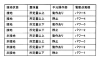
次に、上記第1の実施形態の動作を、図4に示すマトリクスおよび図5に示すフローチャートも参照しながら説明する。   Next, the operation of the first embodiment will be described with reference to the matrix shown in FIG. 4 and the flowchart shown in FIG.

使用者が、集塵部を掃除機本体12内に取り付けた状態で、電源コードを壁面のコンセントなどに接続(プラグイン)すると、制御手段37および電源部38などに対して、商用交流電源eから電源(電圧)が供給(印加)される。   When the user attaches (plugs in) the power cord to a wall outlet or the like with the dust collecting unit mounted in the vacuum cleaner body 12, the commercial AC power source e is supplied to the control means 37 and the power source unit 38. Power (voltage) is supplied (applied) from

制御手段37は、設定ボタン42の操作入力待ちとなり、使用者が設定ボタン42の操作により設定した動作モードで電動送風機18を駆動、または、駆動している電動送風機18を停止する。以下、電動送風機18を自動モード、すなわち制御手段37により入力を自動制御するモードで駆動させた場合の各部の動作を説明する。   The control means 37 waits for an operation input of the setting button 42 and drives the electric blower 18 in the operation mode set by the user by operating the setting button 42 or stops the electric blower 18 being driven. Hereinafter, the operation of each part when the electric blower 18 is driven in the automatic mode, that is, the mode in which the input is automatically controlled by the control means 37 will be described.

使用者は、電動送風機18が駆動した後、把持部41を介して床ブラシ23を被掃除面上で前後に走行させて、被掃除面の塵埃を、駆動した電動送風機18の負圧により風路Wを介して空気とともに吸い込んで集塵部に捕集する。   After the electric blower 18 is driven, the user moves the floor brush 23 back and forth on the surface to be cleaned through the gripping portion 41, and the dust on the surface to be cleaned is blown by the negative pressure of the driven electric blower 18. The air is sucked together with the air through the path W and collected in the dust collecting part.

なお、この掃除状態において、制御手段37は、例えば光センサ33から出力される出力信号を増幅部39により増幅しパルス整形器40によりパルス整形して入力される入力信号によって、風路W内を通過する塵埃量を監視している。換言すれば、電気掃除機11は、光センサ33により塵埃量を検出している(ステップ1)。   In this cleaning state, the control means 37, for example, amplifies the output signal output from the optical sensor 33 by the amplifying unit 39 and performs pulse shaping by the pulse shaper 40 to input the inside of the air path W. The amount of dust passing through is monitored. In other words, the vacuum cleaner 11 detects the amount of dust by the optical sensor 33 (step 1).

すなわち、風路W内を塵埃が通過すると、発光部35の発光素子35aからの発光を塵埃が遮るため、受光部36の受光素子36aでの受光量が減少することで、風路W内を塵埃が通過していることを光センサ33により検出できる。したがって、風路W内を通過する塵埃量が多いほど、受光部36の受光素子36aでの受光量が減少するので、光センサ33からの出力信号が増幅部39により増幅されパルス整形器40によりパルス整形されて制御手段37に入力される入力信号が相対的に小さくなることで、制御手段37は、風路W内を通過する(掃除している被掃除面の位置での)塵埃量の寡多を、上記入力信号の大小によって判断可能となる。   That is, when dust passes through the air path W, the dust blocks light emission from the light emitting element 35a of the light emitting unit 35. Therefore, the amount of light received by the light receiving element 36a of the light receiving unit 36 decreases, so that The passage of dust can be detected by the optical sensor 33. Therefore, as the amount of dust passing through the air path W increases, the amount of light received by the light receiving element 36a of the light receiving unit 36 decreases, so that the output signal from the optical sensor 33 is amplified by the amplification unit 39 and is amplified by the pulse shaper 40. Since the input signal that is pulse-shaped and input to the control means 37 becomes relatively small, the control means 37 can control the amount of dust that passes through the air passage W (at the position of the surface to be cleaned). A large number can be determined by the magnitude of the input signal.

そして、制御手段37は、例えば上記入力信号と予め設定された閾値とを比較することなどにより、光センサ33により検出した塵埃量が予め設定された所定量以上であるかどうかを判断し(ステップ2)、所定量以上でない(所定量未満である)と判断したときには、制御手段37は、動作検出手段45により手元操作部27が動作しているかどうかを判断する(ステップ3)。   Then, the control means 37 determines whether or not the dust amount detected by the optical sensor 33 is equal to or greater than a predetermined amount by comparing the input signal with a preset threshold value (step S40). 2) When it is determined that the amount is not equal to or greater than the predetermined amount (less than the predetermined amount), the control unit 37 determines whether or not the hand operating unit 27 is operating by the operation detecting unit 45 (step 3).

このステップ3において、手元操作部27が動作していない(手元操作部27が静止している)と制御手段37が判断したときには、例えば使用者が手元操作部27を把持しておらず、通常どおりの掃除をしていない状態、例えば電気掃除機11(電動送風機18)を駆動させたまま、風路形成体13を放置している掃除状態などと想定して、制御手段37は、トライアックTr1により設定する電動送風機18の入力の位相角を最も小さい所定の最小値である所定の電動送風機用第1値として、電動送風機18を最低入力である所定の第1電動送風機入力(パワー1)で動作させる(ステップ4)。   In step 3, when the control means 37 determines that the hand operation unit 27 is not operating (the hand operation unit 27 is stationary), for example, the user does not hold the hand operation unit 27, Assuming that the vacuum cleaner 11 (the electric blower 18) is driven, for example, a cleaning state in which the air passage forming body 13 is left unattended, the control means 37 is configured as a triac Tr1. The phase angle of the input of the electric blower 18 set by the above is set to a predetermined first value for the electric blower that is the smallest predetermined minimum value, and the electric blower 18 is set to a predetermined first electric blower input (power 1) that is the lowest input. Operate (step 4).

また、ステップ3において、手元操作部27が動作している(手元操作部27が静止していない)と制御手段37が判断したときには、例えば使用者が通常どおり前後に床ブラシ23を往復動させて掃除をしているものの、被掃除面の塵埃量が少ない掃除状態などと想定して、この制御手段37は、トライアックTr1により設定する電動送風機18の入力の位相角を電動送風機用第1値よりも大きい所定の電動送風機用第2値として、電動送風機18を第1電動送風機入力よりも大きい所定の第2電動送風機入力(パワー2)で動作させる(ステップ5)。   In step 3, when the control means 37 determines that the hand operation unit 27 is operating (the hand operation unit 27 is not stationary), for example, the user reciprocates the floor brush 23 back and forth as usual. This control means 37 assumes that the phase angle of the input of the electric blower 18 set by the triac Tr1 is the first value for the electric blower. The electric blower 18 is operated with a predetermined second electric blower input (power 2) larger than the first electric blower input as the second value for the predetermined electric blower larger than the first electric blower (step 5).

一方、ステップ2において、光センサ33により検出した塵埃量が所定量以上であると判断したときには、制御手段37は、動作検出手段45により手元操作部27が動作しているかどうかを判断する(ステップ6)。   On the other hand, when it is determined in step 2 that the amount of dust detected by the optical sensor 33 is greater than or equal to a predetermined amount, the control means 37 determines whether or not the hand operating section 27 is operating by the operation detecting means 45 (step 6).

このステップ6において、手元操作部27が動作していない(手元操作部27が静止している)と制御手段37が判断したときには、例えば壁際などに部分的に塵埃が溜まっている場所の掃除状態などと想定して、制御手段37は、トライアックTr1により設定する電動送風機18の入力の位相角を電動送風機用第2値よりも大きい所定の電動送風機用第3値として、電動送風機18を第2電動送風機入力よりも大きい所定の第3電動送風機入力(パワー3)で動作させる(ステップ7)。   In this step 6, when the control means 37 determines that the hand operation section 27 is not operating (the hand operation section 27 is stationary), for example, a cleaning state of a place where dust is partially accumulated near the wall or the like Assuming that, the control means 37 sets the electric blower 18 to the second value by setting the phase angle of the input of the electric blower 18 set by the triac Tr1 as a predetermined third value for the electric blower larger than the second value for the electric blower. Operation is performed with a predetermined third electric blower input (power 3) larger than the electric blower input (step 7).

また、ステップ6において、手元操作部27が動作している(手元操作部27が静止していない)と制御手段37が判断したときには、例えば被掃除面の塵埃量が多く、かつ、使用者が通常どおり前後に床ブラシ23を往復動させて掃除をしている掃除状態などと想定して、この制御手段37は、トライアックTr1により設定する電動送風機18の入力の位相角を電動送風機用第3値よりも大きい所定の電動送風機用第4値として、電動送風機18を第3入力よりも大きい所定の第4電動送風機入力(パワー4)で動作させる(ステップ8)。   In Step 6, when the control means 37 determines that the hand operation unit 27 is operating (the hand operation unit 27 is not stationary), for example, the amount of dust on the surface to be cleaned is large, and the user Assuming that the floor brush 23 is reciprocated back and forth as usual for cleaning, the control means 37 determines the phase angle of the input of the electric blower 18 set by the triac Tr1 for the third electric blower. The electric blower 18 is operated with a predetermined fourth electric blower input (power 4) larger than the third input as a predetermined fourth value for electric blower larger than the value (step 8).

すなわち、光センサ33により検出した塵埃量、および、動作検出手段45で検出した手元操作部27の動作状態に基づいて掃除状態を想定し、その想定した掃除状態に対応して、制御手段37が電動送風機18の駆動(入力)を制御することで、光センサ33からの情報と動作検出手段45からの情報との2つの情報に基づいて使用者の掃除状態を精度よく想定でき、掃除状態に適した電力で掃除できる。   That is, a cleaning state is assumed based on the amount of dust detected by the optical sensor 33 and the operation state of the hand operation unit 27 detected by the operation detection unit 45, and the control unit 37 corresponds to the assumed cleaning state. By controlling the driving (input) of the electric blower 18, it is possible to accurately assume the user's cleaning state based on two pieces of information, the information from the optical sensor 33 and the information from the motion detection means 45, and to the cleaning state. It can be cleaned with suitable power.

次に、第2の実施形態を図6ないし図9を参照して説明する。なお、上記第1の実施形態と同様の構成および作用については、同一符号を付してその説明を省略する。   Next, a second embodiment will be described with reference to FIGS. In addition, about the structure and effect | action similar to the said 1st Embodiment, the same code | symbol is attached | subjected and the description is abbreviate | omitted.

この第2の実施形態は、上記第1の実施形態において、床ブラシ23に、回転清掃体としての回転ブラシ51を備えるものである。   In the second embodiment, the floor brush 23 is provided with a rotating brush 51 as a rotating cleaning body in the first embodiment.

すなわち、床ブラシ23は、図7に示すように、ケース体48の被掃除面に対向する下面に開口形成された横長の吸込口に回転ブラシ51が回転可能に取り付けられている。この回転ブラシ51は、ケース体48内に収容された電動機52に対してベルトなどの伝達手段53を介して連結され、この電動機52により回転駆動される。   That is, as shown in FIG. 7, the floor brush 23 has a rotary brush 51 rotatably attached to a horizontally long suction port formed in the lower surface facing the surface to be cleaned of the case body 48. The rotating brush 51 is connected to an electric motor 52 accommodated in the case body 48 via a transmission means 53 such as a belt, and is rotated by the electric motor 52.

回転ブラシ51は、被掃除面に入り込んだり絡み付いたりした塵埃を回転により掻き取るものである。この回転ブラシ51は任意の構成とすることができるが、例えば毛ブラシ、あるいはブレードなどの清掃部材を備えることが好ましい。   The rotating brush 51 scrapes off dust that has entered or entangled with the surface to be cleaned by rotation. The rotating brush 51 can have an arbitrary configuration, but preferably includes a cleaning member such as a bristle brush or a blade.

電動機52は、図6に示すように、制御手段37により、電動機制御素子としてのトライアックTr2を介して位相制御される。また、この電動機52は、電気掃除機11(電動送風機18)のオンオフと同時に(オンオフに対応して)、オンオフされるものとする。なお、これら制御手段37と電動機52(トライアックTr2)とは、風路形成体13の内部を通る図示しない配線により電気的に接続されている。   As shown in FIG. 6, the phase of the electric motor 52 is controlled by the control means 37 via a triac Tr2 as an electric motor control element. The electric motor 52 is turned on / off simultaneously with the on / off of the electric vacuum cleaner 11 (electric blower 18) (corresponding to the on / off). The control means 37 and the electric motor 52 (triac Tr2) are electrically connected by a wiring (not shown) that passes through the inside of the air passage forming body 13.

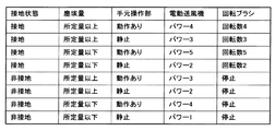
次に、上記第2の実施形態の動作を、図8に示すマトリクスおよび図9に示すフローチャートも参照しながら説明する。   Next, the operation of the second embodiment will be described with reference to the matrix shown in FIG. 8 and the flowchart shown in FIG.

上記第1の実施形態のステップ3において、手元操作部27が動作していない(手元操作部27が静止している)と制御手段37が判断したときには、例えば使用者が手元操作部27を把持しておらず、通常どおりの掃除をしていない状態、例えば電気掃除機11(電動送風機18)を駆動させたまま、風路形成体13を放置している掃除状態などと想定して、制御手段37は、トライアックTr1により設定する電動送風機18の入力の位相角を上記電動送風機用第1値として、電動送風機18を上記第1電動送風機入力(パワー1)で動作させるとともに、トライアックTr2により設定する電動機52の入力の位相角を最も小さい所定の最小値である所定の電動機用第1値として、電動機52を最低入力である所定の第1電動機入力で動作させることにより、回転ブラシ51を最低回転数である所定の第1回転数(回転数1)で回転させる(ステップ11)。   In step 3 of the first embodiment, when the control unit 37 determines that the hand operation unit 27 is not operating (the hand operation unit 27 is stationary), for example, the user holds the hand operation unit 27. Control, assuming that the vacuum cleaner 11 (electric blower 18) is driven and the air path forming body 13 is left unattended, such as a cleaning state in which the air path forming body 13 is left unattended. The means 37 sets the phase angle of the input of the electric blower 18 set by the triac Tr1 as the first value for the electric blower, operates the electric blower 18 with the first electric blower input (power 1), and sets it with the triac Tr2. By setting the phase angle of the input of the motor 52 to be the first predetermined value for the predetermined motor, which is the smallest predetermined minimum value, by operating the motor 52 with the predetermined first motor input that is the lowest input, the rotary brush 51 is minimized. In revolutions That is rotated at a predetermined first revolution speed (rpm 1) (step 11).

また、ステップ3において、手元操作部27が動作している(手元操作部27が静止していない)と制御手段37が判断したときには、例えば使用者が通常どおり前後に床ブラシ23を往復動させて掃除をしているものの、被掃除面の塵埃量が少ない掃除状態などと想定して、この制御手段37は、トライアックTr1により設定する電動送風機18の入力の位相角を上記電動送風機用第2値として、電動送風機18を上記第2電動送風機入力(パワー2)で動作させるとともに、トライアックTr2により設定する電動機52の入力の位相角を電動機用第1値よりも大きい所定の電動機用第2値として、電動機52を第1電動機入力よりも大きい所定の第2電動機入力で動作させることにより、回転ブラシ51を第1回転数よりも大きい所定の第2回転数(回転数2)で回転させる(ステップ12)。   In step 3, when the control means 37 determines that the hand operation unit 27 is operating (the hand operation unit 27 is not stationary), for example, the user reciprocates the floor brush 23 back and forth as usual. However, the control means 37 sets the phase angle of the input of the electric blower 18 set by the triac Tr1 as the second electric blower for the electric blower. As a value, the electric blower 18 is operated by the second electric blower input (power 2) and the phase angle of the input of the electric motor 52 set by the triac Tr2 is a predetermined second value for the motor that is larger than the first value for the motor. As described above, by operating the motor 52 with a predetermined second motor input larger than the first motor input, the rotary brush 51 is rotated at a predetermined second rotation speed (rotation speed 2) larger than the first rotation speed ( Ste Flop 12).

さらに、ステップ6において、手元操作部27が動作していない(手元操作部27が静止している)と制御手段37が判断したときには、例えば絨毯の壁際など部分的に多くの塵埃が溜まっている場所の掃除状態などと想定して、制御手段37は、トライアックTr1により設定する電動送風機18の入力の位相角を上記電動送風機用第3値として、電動送風機18を上記第3電動送風機入力(パワー3)で動作させるとともに、トライアックTr2により設定する電動機52の入力の位相角を電動機用第2値よりも大きい所定の電動機用第3値として、電動機52を第2電動機入力よりも大きい所定の第3電動機入力で動作させることにより、回転ブラシ51を第2回転数よりも大きい所定の第3回転数(回転数3)で回転させる(ステップ13)。   Furthermore, when the control unit 37 determines in step 6 that the hand operation unit 27 is not operating (the hand operation unit 27 is stationary), a large amount of dust is accumulated, for example, near the wall of the carpet. Assuming a clean state of the place, the control means 37 uses the phase angle of the input of the electric blower 18 set by the triac Tr1 as the third value for the electric blower, and sets the electric blower 18 to the third electric blower input (power 3), the phase angle of the input of the motor 52 set by the triac Tr2 is set to a predetermined third value for the motor larger than the second value for the motor, and the motor 52 is set to a predetermined first value larger than the second motor input. By operating with three electric motor inputs, the rotating brush 51 is rotated at a predetermined third rotational speed (rotational speed 3) larger than the second rotational speed (step 13).

そして、ステップ6において、手元操作部27が動作している(手元操作部27が静止していない)と制御手段37が判断したときには、例えば被掃除面の塵埃量が多く、かつ、使用者が通常どおり前後に床ブラシ23を往復動させて掃除をしている掃除状態などと想定して、この制御手段37は、トライアックTr1により設定する電動送風機18の入力の位相角を上記電動送風機用第4値として、電動送風機18を上記第4電動送風機入力(パワー4)で動作させるとともに、トライアックTr2により設定する電動機52の入力の位相角を電動機用第3値よりも大きい所定の電動機用第4値として、電動機52を第3電動機入力よりも大きい所定の第4電動機入力で動作させることにより、回転ブラシ51を第3回転数よりも大きい所定の第4回転数(回転数4)で回転させる(ステップ14)。   In step 6, when the control means 37 determines that the hand operation unit 27 is operating (the hand operation unit 27 is not stationary), for example, the amount of dust on the surface to be cleaned is large, and the user Assuming that the floor brush 23 is reciprocated back and forth as usual for cleaning, the control means 37 determines the phase angle of the input of the electric blower 18 set by the triac Tr1 for the electric blower As the four values, the electric blower 18 is operated with the fourth electric blower input (power 4), and the phase angle of the input of the electric motor 52 set by the triac Tr2 is larger than the third value for the electric motor. As a value, by operating the motor 52 with a predetermined fourth motor input larger than the third motor input, the rotary brush 51 is rotated at a predetermined fourth rotation speed (rotation speed 4) larger than the third rotation speed. (Stay Flop 14).

このように、制御手段37が、光センサ33により検出した塵埃量、および、動作検出手段45により検出した手元操作部27の動作に基づいて掃除状態を想定し、その想定した掃除状態に対応して電動送風機18および電動機52(回転ブラシ51)の駆動をそれぞれ制御することにより、電動送風機18だけでなく、電動機52(回転ブラシ51)をも掃除状態に適した状態で駆動させることができるので、掃除状態に適した電力で掃除でき、省エネルギ化が可能になるとともに、電動機52(回転ブラシ51)により被掃除面の塵埃を掻き取ることができるので、掃除性能をより向上できる。   Thus, the control means 37 assumes a cleaning state based on the amount of dust detected by the optical sensor 33 and the operation of the hand operation unit 27 detected by the operation detection means 45, and corresponds to the assumed cleaning state. By controlling the driving of the electric blower 18 and the electric motor 52 (the rotating brush 51), not only the electric blower 18, but also the electric motor 52 (the rotating brush 51) can be driven in a state suitable for the cleaning state. Further, cleaning can be performed with electric power suitable for the cleaning state, energy saving can be achieved, and dust on the surface to be cleaned can be scraped off by the electric motor 52 (the rotating brush 51), so that the cleaning performance can be further improved.

次に、第3の実施形態を図10ないし図13を参照して説明する。なお、上記各実施形態と同様の構成および作用については、同一符号を付してその説明を省略する。   Next, a third embodiment will be described with reference to FIGS. In addition, about the structure and effect | action similar to said each embodiment, the same code | symbol is attached | subjected and the description is abbreviate | omitted.

この第3の実施形態は、上記第1の実施形態において、床ブラシ23に、この床ブラシ23の接地状態を検出する接地検出手段55が配置されているものである。   In the third embodiment, in the first embodiment, the floor brush 23 is provided with a grounding detection means 55 for detecting the grounding state of the floor brush 23.

図11に示すように、接地検出手段55は、ケース体48の被掃除面に対向する下面に形成された開口部56に可動的に取り付けられている。また、この接地検出手段55は、接地部としての車輪57と、この車輪57の接地/非接地によりオンオフが切り換えられる図示しない切換スイッチとを有しており、車輪57が支持部材59に回動自在に軸支され、この支持部材59がケース体48に回動可能に軸支されている。そして、床ブラシ23を被掃除面に接触(接地)させると、車輪57が被掃除面に接触することでこの車輪57が支持部材59とともに回動して開口部56に収納され、この回動した支持部材59が切換スイッチをオンさせることで床ブラシ23の接地が検出され、床ブラシ23を被掃除面に対して離間させる(非接地状態にする)と、支持部材59とともに車輪57が開口部56から突出して、切換スイッチに対して支持部材59が離間され、切換スイッチがオフされることで床ブラシ23の非接地が検出されるように構成されている。   As shown in FIG. 11, the ground detection means 55 is movably attached to an opening 56 formed on the lower surface of the case body 48 facing the surface to be cleaned. The grounding detection means 55 has a wheel 57 as a grounding part and a change-over switch (not shown) that is switched on / off by the grounding / non-grounding of the wheel 57. The wheel 57 rotates to the support member 59. The support member 59 is pivotally supported by the case body 48 so as to be rotatable. Then, when the floor brush 23 is brought into contact with the surface to be cleaned (grounded), the wheel 57 contacts the surface to be cleaned so that the wheel 57 rotates together with the support member 59 and is stored in the opening 56. When the support member 59 turns on the changeover switch, the grounding of the floor brush 23 is detected, and when the floor brush 23 is separated from the surface to be cleaned (ungrounded), the wheel 57 opens together with the support member 59. The support member 59 protrudes from the portion 56 and is separated from the changeover switch. When the changeover switch is turned off, the non-grounding of the floor brush 23 is detected.

また、接地検出手段55は、図10に示すように、制御手段37に電気的に接続されており、接地検出手段55の切換スイッチのオンオフを介して、制御手段37が床ブラシ23の接地/非接地を認識できるように構成されている。なお、接地検出手段55と制御手段37とは、風路形成体13の内部を通る図示しない配線により電気的に接続されている。したがって、例えば床ブラシ23を延長管22から取り外している場合、あるいは、延長管22および床ブラシ23を手元操作部27から取り外して他の吸込口体、例えばつる口などを手元操作部27に対して接続している場合には、接地検出手段55と制御手段37との電気的接続が遮断されることにより、制御手段37は床ブラシ23が接地していないと判断するように構成されている。すなわち、接地検出手段55は、床ブラシ23の接地/非接地を検出することにより、床ブラシ23を用いているか、床ブラシ23を取り外して他の吸込口体を用いているかをも間接的に判断する、接続検出手段の機能を有している。このため、以下、制御手段37が接地検出手段55により検出する接地/非接地は、床ブラシ23の接続/非接続も含むものとする。   Further, as shown in FIG. 10, the ground detection means 55 is electrically connected to the control means 37, and the control means 37 is connected to the ground brush 23 by means of an on / off switch of the ground detection means 55. It is configured to recognize non-grounding. The ground contact detection means 55 and the control means 37 are electrically connected by a wiring (not shown) that passes through the inside of the air passage forming body 13. Therefore, for example, when the floor brush 23 is removed from the extension pipe 22, or when the extension pipe 22 and the floor brush 23 are removed from the hand operation section 27, another suction port, such as a vine mouth, is attached to the hand operation section 27. Are connected to each other, the electrical connection between the ground detection means 55 and the control means 37 is cut off, so that the control means 37 is configured to determine that the floor brush 23 is not grounded. . That is, the grounding detection means 55 indirectly detects whether the floor brush 23 is used by detecting the grounding / non-grounding of the floor brush 23 or whether the floor brush 23 is removed and another suction port is used. It has a function of a connection detecting means for judging. For this reason, hereinafter, the ground / non-ground detected by the ground detecting means 55 by the control means 37 includes the connection / non-connection of the floor brush 23.

次に、上記第3の実施形態の動作を、図12に示すマトリクスおよび図13に示すフローチャートも参照しながら説明する。   Next, the operation of the third embodiment will be described with reference to the matrix shown in FIG. 12 and the flowchart shown in FIG.

まず、ステップ3において、手元操作部27が動作していない(手元操作部27が静止している)と制御手段37が判断したときには、この制御手段37は、接地検出手段55により、床ブラシ23が接地しているかどうかを判断する(ステップ21)。   First, in step 3, when the control means 37 determines that the hand operation section 27 is not operating (the hand operation section 27 is stationary), the control means 37 is detected by the ground detection means 55 by the floor brush 23. It is determined whether or not is grounded (step 21).

そして、このステップ21において、床ブラシ23が接地していないと判断したときには、制御手段37は、例えば被掃除面の塵埃量が少なく、使用者が床ブラシ23(および延長管22)を取り外して例えばつる口などの他の吸込口体を接続し、かつ、使用者が手元操作部27を把持しておらず、通常どおりの掃除をしていない状態、例えば電気掃除機11(電動送風機18)を駆動させたまま、風路形成体13を放置している掃除状態などと想定して、制御手段37は、トライアックTr1により設定する電動送風機18の入力の位相角を上記電動送風機用第1値として、電動送風機18を上記第1電動送風機入力(パワー1)で動作させる(ステップ22)。   In step 21, when it is determined that the floor brush 23 is not grounded, the control means 37 has a small amount of dust on the surface to be cleaned, for example, and the user removes the floor brush 23 (and the extension pipe 22). For example, a state in which another suction port body such as a vine mouth is connected and the user does not hold the hand operating unit 27 and is not cleaned as usual, for example, the vacuum cleaner 11 (electric blower 18) Assuming a cleaning state in which the air passage forming body 13 is left with the air passage driven, the control means 37 sets the input phase angle of the electric blower 18 set by the triac Tr1 as the first value for the electric blower. Then, the electric blower 18 is operated by the first electric blower input (power 1) (step 22).

また、ステップ21において、床ブラシ23が接地していると判断したときには、制御手段37は、例えば被掃除面の塵埃量が少ないものの、例えば床ブラシ23を被掃除面に接地させて壁際など部分的に塵埃が溜まっている場所の掃除状態などと想定して、制御手段37は、トライアックTr1により設定する電動送風機18の入力の位相角を上記電動送風機用第2値として、電動送風機18を上記第2電動送風機入力(パワー2)で動作させる(ステップ23)。   Further, when it is determined in step 21 that the floor brush 23 is grounded, the control means 37, for example, has a small amount of dust on the surface to be cleaned. The control means 37 assumes that the phase angle of the input of the electric blower 18 set by the triac Tr1 is the second value for the electric blower, and assumes the electric blower 18 as described above. It operates with the second electric blower input (power 2) (step 23).

また、ステップ3において、手元操作部27が動作している(手元操作部27が静止していない)と制御手段37が判断したときには、ステップ21と同様に、制御手段37は、接地検出手段55により、床ブラシ23が接地しているかどうかを判断する(ステップ24)。   In step 3, when the control unit 37 determines that the hand operation unit 27 is operating (the hand operation unit 27 is not stationary), the control unit 37 is connected to the ground detection unit 55 as in step 21. Thus, it is determined whether or not the floor brush 23 is grounded (step 24).

そして、このステップ24において、床ブラシ23が接地していないと判断したときには、制御手段37は、例えば被掃除面の塵埃量が少ないものの、例えば床ブラシ23(および延長管22)を取り外してつる口などの他の吸込口体を接続して掃除している掃除状態などと想定して、制御手段37は、トライアックTr1により設定する電動送風機18の入力の位相角を上記電動送風機用第2値として、電動送風機18を上記第2電動送風機入力(パワー2)で動作させる(ステップ25)。   In step 24, when it is determined that the floor brush 23 is not grounded, the control means 37 suspends the floor brush 23 (and the extension pipe 22), for example, although the amount of dust on the surface to be cleaned is small. Assuming a cleaning state in which another suction port body such as a mouth is connected for cleaning, the control means 37 sets the phase angle of the input of the electric blower 18 set by the triac Tr1 to the second value for the electric blower. Then, the electric blower 18 is operated with the second electric blower input (power 2) (step 25).

また、ステップ24において、床ブラシ23が接地していると判断したときには、制御手段37は、例えば被掃除面の塵埃量が少ないものの、床ブラシ23を被掃除面に接地させて掃除している掃除状態などと想定して、制御手段37は、トライアックTr1により設定する電動送風機18の入力の位相角を上記電動送風機用第3値として、電動送風機18を上記第3電動送風機入力(パワー3)で動作させる(ステップ26)。   Further, when it is determined in step 24 that the floor brush 23 is grounded, the control means 37 performs cleaning by grounding the floor brush 23 on the surface to be cleaned although the amount of dust on the surface to be cleaned is small, for example. Assuming a cleaning state, the control means 37 sets the phase angle of the input of the electric blower 18 set by the triac Tr1 as the third value for the electric blower, and makes the electric blower 18 the third electric blower input (power 3). (Step 26).

一方、ステップ6において、手元操作部27が動作していない(手元操作部27が静止している)と制御手段37が判断したときには、ステップ21,24と同様に、制御手段37は、接地検出手段55により、床ブラシ23が接地しているかどうかを判断する(ステップ27)。   On the other hand, in step 6, when the control means 37 determines that the hand operation section 27 is not operating (the hand operation section 27 is stationary), the control means 37 detects the ground contact in the same manner as steps 21 and 24. It is determined by means 55 whether the floor brush 23 is grounded (step 27).

そして、このステップ27において、床ブラシ23が接地していないと判断したときには、制御手段37は、例えば家具と壁との隙間などの狭い場所に、例えば床ブラシ23を取り外してつる口などの他の吸込口体を接続し、吸込風量によって溜まっている塵埃を吸い込むために、所定の時間、吸込口体を静止させて掃除する掃除状態などと想定して、制御手段37は、トライアックTr1により設定する電動送風機18の入力の位相角を上記電動送風機用第3値として、電動送風機18を上記第3電動送風機入力(パワー3)で動作させる(ステップ28)。   In step 27, when it is determined that the floor brush 23 is not grounded, the control means 37, for example, removes the floor brush 23 in a narrow space such as a gap between the furniture and the wall. The control means 37 is set by the TRIAC Tr1, assuming that the suction port body is stationary and cleaned for a predetermined time in order to connect the suction port body and suck in the dust accumulated by the suction air volume. The electric blower 18 is operated with the third electric blower input (power 3) by setting the phase angle of the input of the electric blower 18 to be the third value for the electric blower (step 28).

また、ステップ27において、床ブラシ23が接地していると判断したときには、制御手段37は、例えば被掃除面の隅、あるいは壁際などを床ブラシ23により掃除している掃除状態などと想定して、制御手段37は、トライアックTr1により設定する電動送風機18の入力の位相角を上記電動送風機用第4値として、電動送風機18を上記第4電動送風機入力(パワー4)で動作させる(ステップ29)。   Further, when it is determined in step 27 that the floor brush 23 is grounded, the control means 37 assumes a cleaning state in which, for example, the corner of the surface to be cleaned or the wall is cleaned with the floor brush 23. The control means 37 operates the electric blower 18 with the fourth electric blower input (power 4) with the phase angle of the input of the electric blower 18 set by the triac Tr1 as the fourth value for the electric blower (step 29). .

さらに、ステップ6において、手元操作部27が動作している(手元操作部27が静止していない)と制御手段37が判断したときには、ステップ21,24,27と同様に、制御手段37は、接地検出手段55により、床ブラシ23が接地しているかどうかを判断する(ステップ30)。   Further, when the control unit 37 determines in step 6 that the hand operation unit 27 is operating (the hand operation unit 27 is not stationary), as in steps 21, 24 and 27, the control unit 37 The ground detection means 55 determines whether or not the floor brush 23 is grounded (step 30).

そして、このステップ30において、床ブラシ23が接地していないと判断したときには、制御手段37は、例えば塵埃量が多い棚の上など広範囲の被掃除面に対して、例えば床ブラシ23(および延長管22)を取り外して家具ブラシなどの他の吸込口体を用いて掃除している掃除状態などと想定して、制御手段37は、トライアックTr1により設定する電動送風機18の入力の位相角を上記電動送風機用第4値として、電動送風機18を上記第4電動送風機入力(パワー4)で動作させる(ステップ31)。   When it is determined in step 30 that the floor brush 23 is not grounded, the control means 37 applies, for example, the floor brush 23 (and extension) to a wide range of surfaces to be cleaned, such as on a shelf with a large amount of dust. Assuming that the pipe 22) is removed and cleaning is performed using another suction port such as a furniture brush, the control means 37 sets the input phase angle of the electric blower 18 set by the triac Tr1 as described above. As the fourth value for the electric blower, the electric blower 18 is operated with the fourth electric blower input (power 4) (step 31).

また、ステップ30において、床ブラシ23が接地していると判断したときには、制御手段37は、例えば被掃除面の塵埃量が多く、かつ、使用者が床ブラシ23を接地させて通常どおり前後に床ブラシ23を往復動させて掃除をしている掃除状態などと想定して、制御手段37は、トライアックTr1により設定する電動送風機18の入力の位相角を電動送風機用第4値よりも大きい最大値である所定の電動送風機用第5値として、電動送風機18を第4電動送風機入力よりも大きい最大入力である所定の第5電動送風機入力(パワー5)で動作させる(ステップ32)。   Further, when it is determined in step 30 that the floor brush 23 is grounded, the control means 37, for example, has a large amount of dust on the surface to be cleaned, and the user grounds the floor brush 23 and moves back and forth as usual. Assuming that the floor brush 23 is reciprocated for cleaning, the control means 37 sets the maximum phase angle of the input of the electric blower 18 set by the triac Tr1 to be larger than the fourth value for the electric blower. The electric blower 18 is operated with a predetermined fifth electric blower input (power 5) which is a maximum input larger than the fourth electric blower input as the predetermined fifth value for electric blower (step 32).

このように、床ブラシ23、あるいはつる口などの吸込口体の接地状態(接続状態)を接地検出手段55により検出し、制御手段37が、光センサ33により検出した塵埃量、動作検出手段45により検出した手元操作部27の動作、および、接地検出手段55により検出した吸込口体の接地状態(接続状態)に基づいて掃除状態を想定し、その想定した掃除状態に対応して電動送風機18の駆動を制御することで、使用者の掃除状態を、光センサ33からの情報と動作検出手段45からの情報と接地検出手段55からの情報との3つの情報に基づいて、より精度よく想定することが可能になり、掃除状態により適した電力で掃除でき、一層の省エネルギ化が可能になる。すなわち、例えば床ブラシ23が接地しているとき(接続されているとき)には、床ブラシ23を接地していないとき(接続していないとき)よりも電動送風機18の入力(パワー(吸込力))を増加させているので、例えばパワーが必要となる床ブラシ23を用いて床面などの被掃除面を掃除するときと、床ブラシ23と比較して開口面積が狭く電動送風機18のパワーが小さくてよい、つる口などの吸込口体を用いた掃除のときとを制御手段37が識別でき、電動送風機18の入力をより適正に設定できる。   In this way, the grounding state (connection state) of the suction inlet body such as the floor brush 23 or the sill mouth is detected by the grounding detection means 55, and the control unit 37 detects the amount of dust detected by the optical sensor 33 and the motion detection means 45. Assuming the cleaning state based on the operation of the hand operating unit 27 detected by the above and the grounding state (connection state) of the suction port body detected by the grounding detection means 55, the electric blower 18 corresponding to the assumed cleaning state By controlling the drive, the user's cleaning state is assumed more accurately based on the three types of information: the information from the optical sensor 33, the information from the motion detection means 45, and the information from the ground detection means 55. It is possible to perform cleaning with electric power more suitable for the cleaning state, and further energy saving is possible. That is, for example, when the floor brush 23 is grounded (connected), the input (power (suction force) of the electric blower 18 is higher than when the floor brush 23 is not grounded (not connected). )) Is increased, for example, when the surface to be cleaned such as the floor surface is cleaned using the floor brush 23 that requires power, the opening area is smaller than the floor brush 23 and the power of the electric blower 18 is reduced. The control means 37 can discriminate from the time of cleaning using a suction port body such as a vine port, and the input of the electric blower 18 can be set more appropriately.

なお、上記第1の実施形態および第3の実施形態において、床ブラシ23には、上記第2実施形態の回転ブラシ51および電動機52を備える構成としてもよいが、電動機52(回転ブラシ51)は、電動送風機18と独立して制御するものとする。   In the first embodiment and the third embodiment, the floor brush 23 may include the rotary brush 51 and the electric motor 52 of the second embodiment, but the electric motor 52 (the rotary brush 51) It is assumed that the electric blower 18 is controlled independently.

次に、第4の実施形態を図14ないし図16を参照して説明する。なお、上記各実施形態と同様の構成および作用については、同一符号を付してその説明を省略する。   Next, a fourth embodiment will be described with reference to FIGS. In addition, about the structure and effect | action similar to said each embodiment, the same code | symbol is attached | subjected and the description is abbreviate | omitted.

この第4の実施形態は、図14に示すように、上記第2の実施形態において、上記第3の実施形態の接地検出手段55を備えるものである。   As shown in FIG. 14, the fourth embodiment includes the ground detection means 55 of the third embodiment in the second embodiment.

そして、図15に示すマトリクスおよび図16に示すフローチャートを参照しながら説明すると、ステップ21において、床ブラシ23が接地していないと判断したときには、例えば被掃除面の塵埃量が少なく、かつ、使用者が床ブラシ23を被掃除面に対して浮かせたまま風路形成体13を放置している掃除状態などと想定して、制御手段37は、トライアックTr1により設定する電動送風機18の入力の位相角を上記電動送風機用第1値として、電動送風機18を上記第1電動送風機入力(パワー1)で動作させるとともに、トライアックTr2により設定する電動機52の入力の位相角を0として、電動機52すなわち回転ブラシ51を停止させる(ステップ41)。   Then, with reference to the matrix shown in FIG. 15 and the flowchart shown in FIG. 16, when it is determined in step 21 that the floor brush 23 is not grounded, for example, the amount of dust on the surface to be cleaned is small and used. The control means 37 assumes the phase of the input of the electric blower 18 set by the TRIAC Tr1, assuming that the person is leaving the air passage forming body 13 while the floor brush 23 is floating above the surface to be cleaned. When the angle is set to the first value for the electric blower, the electric blower 18 is operated with the first electric blower input (power 1), and the phase angle of the input of the electric motor 52 set by the triac Tr2 is set to 0. The brush 51 is stopped (step 41).

また、ステップ21において、床ブラシ23が接地していると判断したときには、制御手段37は、例えば床ブラシ23を被掃除面に接地させて塵埃量の少ない壁際などに押し付けて静止した掃除状態などと想定して、制御手段37は、トライアックTr1により設定する電動送風機18の入力の位相角を上記電動送風機用第2値として、電動送風機18を上記第2電動送風機入力(パワー2)で動作させるとともに、トライアックTr2により設定する電動機52の入力の位相角を上記電動機用第2値として、電動機52を上記第2電動機入力で動作させることにより、回転ブラシ51を上記第2回転数(回転数2)で回転させる(ステップ42)。   Further, when it is determined in step 21 that the floor brush 23 is grounded, the control means 37 is, for example, a cleaning state where the floor brush 23 is grounded to the surface to be cleaned and pressed against the wall with a small amount of dust, etc. Assuming that, the control means 37 operates the electric blower 18 with the second electric blower input (power 2) with the phase angle of the input of the electric blower 18 set by the triac Tr1 as the second value for the electric blower. At the same time, by setting the phase angle of the input of the motor 52 set by the triac Tr2 as the second value for the motor, and operating the motor 52 with the second motor input, the rotary brush 51 is moved to the second rotational speed (the rotational speed 2). ) (Step 42).

同様に、ステップ24において、床ブラシ23が接地していないと判断したときには、制御手段37は、例えば被掃除面の塵埃量が少ないものの、例えば床ブラシ23(および延長管22)を取り外してつる口などの他の吸込口体を用いて掃除している掃除状態などと想定して、制御手段37は、トライアックTr1により設定する電動送風機18の入力の位相角を上記電動送風機用第2値として、電動送風機18を上記第2電動送風機入力(パワー2)で動作させるとともに、トライアックTr2により設定する電動機52の入力の位相角を0として、電動機52すなわち回転ブラシ51を停止させる(ステップ43)。   Similarly, when it is determined in step 24 that the floor brush 23 is not grounded, the control means 37 suspends the floor brush 23 (and the extension tube 22), for example, although the amount of dust on the surface to be cleaned is small. Assuming a cleaning state in which another suction port body such as a mouth is used for cleaning, the control means 37 sets the input phase angle of the electric blower 18 set by the triac Tr1 as the second value for the electric blower. Then, the electric blower 18 is operated with the second electric blower input (power 2), and the phase angle of the input of the electric motor 52 set by the triac Tr2 is set to 0, and the electric motor 52, that is, the rotating brush 51 is stopped (step 43).

また、ステップ24において、床ブラシ23が接地していると判断したときには、制御手段37は、例えば被掃除面の塵埃量が少ないものの、床ブラシ23を被掃除面に接地させて掃除している掃除状態などと想定して、制御手段37は、トライアックTr1により設定する電動送風機18の入力の位相角を上記電動送風機用第3値として、電動送風機18を上記第3電動送風機入力(パワー3)で動作させるとともに、トライアックTr2により設定する電動機52の入力の位相角を上記電動機用第3値として、電動機52を上記第3電動機入力で動作させることにより、回転ブラシ51を上記第3回転数(回転数3)で回転させる(ステップ44)。   Further, when it is determined in step 24 that the floor brush 23 is grounded, the control means 37 performs cleaning by grounding the floor brush 23 on the surface to be cleaned although the amount of dust on the surface to be cleaned is small, for example. Assuming a cleaning state, the control means 37 sets the phase angle of the input of the electric blower 18 set by the triac Tr1 as the third value for the electric blower, and makes the electric blower 18 the third electric blower input (power 3). And the phase angle of the input of the motor 52 set by the triac Tr2 is set to the third value for the motor, and the motor 52 is operated with the third motor input, whereby the rotary brush 51 is moved to the third rotational speed ( It is rotated at a rotation speed 3) (step 44).

さらに、ステップ27において、床ブラシ23が接地していないと判断したときには、制御手段37は、例えば家具と壁との隙間などの狭い場所に、例えば床ブラシ23を取り外してつる口などの他の吸込口体を接続し、吸込風量によって溜まっている塵埃を吸い込むために、所定の時間、吸込口体を静止させて掃除する掃除状態などと想定して、制御手段37は、トライアックTr1により設定する電動送風機18の入力の位相角を上記電動送風機用第3値として、電動送風機18を上記第3電動送風機入力(パワー3)で動作させるとともに、トライアックTr2により設定する電動機52の入力の位相角を0として、電動機52すなわち回転ブラシ51を停止させる(ステップ45)。   Further, when it is determined in step 27 that the floor brush 23 is not grounded, the control means 37 can remove the floor brush 23 in a narrow place such as a gap between the furniture and the wall, for example. The control means 37 is set by the triac Tr1, assuming a cleaning state in which the suction port body is stationary and cleaned for a predetermined time in order to connect the suction port body and suck in the dust accumulated by the suction air volume. The phase angle of the input of the electric blower 18 is set as the third value for the electric blower, and the electric blower 18 is operated by the third electric blower input (power 3), and the phase angle of the input of the electric motor 52 set by the triac Tr2 is set. As 0, the electric motor 52, that is, the rotating brush 51 is stopped (step 45).

また、ステップ27において、床ブラシ23が接地していると判断したときには、制御手段37は、例えば被掃除面の隅、あるいは壁際などを床ブラシ23により掃除しようとしている掃除状態などと想定して、制御手段37は、トライアックTr1により設定する電動送風機18の入力の位相角を上記電動送風機用第4値として、電動送風機18を上記第4電動送風機入力(パワー4)で動作させるとともに、トライアックTr2により設定する電動機52の入力の位相角を上記電動機用第4値として、電動機52を上記第4電動機入力で動作させることにより、回転ブラシ51を上記第4回転数(回転数4)で回転させる(ステップ46)。   Further, when it is determined in step 27 that the floor brush 23 is grounded, the control means 37 assumes that the floor brush 23 is cleaning the corner of the surface to be cleaned or near the wall, for example. The control means 37 operates the electric blower 18 with the fourth electric blower input (power 4) with the phase angle of the input of the electric blower 18 set by the triac Tr1 as the fourth value for the electric blower, and the triac Tr2 The rotational phase of the rotary brush 51 is rotated at the fourth rotational speed (revolution speed 4) by setting the phase angle of the input of the motor 52 to the fourth value for the motor and operating the motor 52 with the fourth motor input. (Step 46).

そして、ステップ30において、床ブラシ23が接地していないと判断したときには、制御手段37は、例えば塵埃量が多い棚の上など広範囲の被掃除面に対して、例えば床ブラシ23(および延長管22)を取り外して家具ブラシなどの他の吸込口体を用いて掃除している掃除状態などと想定して、制御手段37は、トライアックTr1により設定する電動送風機18の入力の位相角を上記電動送風機用第4値として、電動送風機18を上記第4電動送風機入力(パワー4)で動作させるとともに、トライアックTr2により設定する電動機52の入力の位相角を0として、電動機52すなわち回転ブラシ51を停止させる(ステップ47)。   When it is determined in step 30 that the floor brush 23 is not grounded, the control means 37 applies, for example, the floor brush 23 (and the extension pipe) to a wide range of surfaces to be cleaned such as a shelf with a large amount of dust. 22) and the control means 37 sets the phase angle of the input of the electric blower 18 set by the triac Tr1 to the above-mentioned electric motor. As the fourth value for the blower, the electric blower 18 is operated by the fourth electric blower input (power 4) and the phase angle of the input of the electric motor 52 set by the triac Tr2 is set to 0, and the electric motor 52, that is, the rotating brush 51 is stopped. (Step 47).

また、ステップ30において、床ブラシ23が接地していると判断したときには、制御手段37は、例えば被掃除面の塵埃量が多く、かつ、使用者が床ブラシ23を接地させて通常どおり前後に床ブラシ23を往復動させて掃除をしている掃除状態などと想定して、制御手段37は、トライアックTr1により設定する電動送風機18の入力の位相角を上記電動送風機用第5値として、電動送風機18を上記第5電動送風機入力(パワー5)で動作させるとともに、トライアックTr2により設定する電動機52の入力の位相角を電動機用第4値よりも大きい最大値である所定の電動機用第5値として、電動機52を第4電動機入力よりも大きい最大入力である所定の第5電動機入力で動作させることにより、回転ブラシ51を第4回転数よりも大きい最大回転数である所定の第5回転数(回転数5)で回転させる(ステップ48)。   Further, when it is determined in step 30 that the floor brush 23 is grounded, the control means 37, for example, has a large amount of dust on the surface to be cleaned, and the user grounds the floor brush 23 and moves back and forth as usual. Assuming a cleaning state in which the floor brush 23 is reciprocated, the control means 37 sets the phase angle of the input of the electric blower 18 set by the triac Tr1 as the fifth value for the electric blower. The blower 18 is operated with the fifth electric blower input (power 5), and the phase angle of the input of the motor 52 set by the triac Tr2 is a predetermined fifth value for the motor which is a maximum value larger than the fourth value for the motor. As described above, by operating the motor 52 with a predetermined fifth motor input which is a maximum input larger than the fourth motor input, the rotary brush 51 is operated with a predetermined fifth rotation which is a maximum rotation speed larger than the fourth rotation speed. Rotating at (rotation speed 5) (step 48).

このように、床ブラシ23、あるいはつる口などの吸込口体の接地状態(接続状態)を接地検出手段55により検出し、制御手段37が、光センサ33により検出した塵埃量、動作検出手段45により検出した手元操作部27の動作、および、接地検出手段55により検出した吸込口体の接地状態(接続状態)に対応して電動送風機18および電動機52(回転ブラシ51)の駆動を制御することで、使用者の掃除状態を、より精度よく想定することが可能になり、掃除状態により適した電力で掃除でき、一層の省エネルギ化が可能になる。すなわち、例えば床ブラシ23が接地しているとき(接続されているとき)には、床ブラシ23を接地していないとき(接続していないとき)よりも電動送風機18の入力(パワー)を増加させているので、例えばパワーが必要となる床ブラシ23を用いて床面などの被掃除面を掃除するときと、床ブラシ23と比較してパワーが小さくてよい、つる口などの吸込口体を用いた掃除のときとを制御手段37が識別でき、電動送風機18の入力をより適正に設定できる。しかも、接地検出手段55が床ブラシ23の非接地(非接続)を検出したときには、電動機52(回転ブラシ51)を停止させるので、不要な消費電力を抑制して、より一層の省エネルギ化が可能になる。   In this way, the grounding state (connection state) of the suction inlet body such as the floor brush 23 or the sill mouth is detected by the grounding detection means 55, and the control unit 37 detects the amount of dust detected by the optical sensor 33 and the motion detection means 45. The operation of the electric blower 18 and the electric motor 52 (the rotating brush 51) is controlled in accordance with the operation of the hand operating unit 27 detected by the above and the grounding state (connection state) of the suction port body detected by the grounding detection means 55. Therefore, it becomes possible to assume the cleaning state of the user with higher accuracy, and the cleaning can be performed with electric power more suitable for the cleaning state, and further energy saving can be achieved. That is, for example, when the floor brush 23 is grounded (connected), the input (power) of the electric blower 18 is increased more than when the floor brush 23 is not grounded (not connected). For example, when cleaning the surface to be cleaned such as the floor surface using the floor brush 23 that requires power, the suction mouth body such as a vine mouth, etc., which requires less power than the floor brush 23. The control means 37 can discriminate from the time of cleaning using the, and the input of the electric blower 18 can be set more appropriately. Moreover, since the electric motor 52 (the rotating brush 51) is stopped when the grounding detecting means 55 detects that the floor brush 23 is not grounded (not connected), unnecessary power consumption is suppressed, and further energy saving is achieved. It becomes possible.

次に、第5の実施形態を図17および図18を参照して説明する。なお、上記各実施形態と同様の構成および作用については、同一符号を付してその説明を省略する。   Next, a fifth embodiment will be described with reference to FIGS. In addition, about the structure and effect | action similar to said each embodiment, the same code | symbol is attached | subjected and the description is abbreviate | omitted.

この第5の実施形態は、基本的に上記第4の実施形態と同様の構成を有しているが、制御手段37による制御が上記第4の実施形態と異なるものである。   The fifth embodiment basically has the same configuration as that of the fourth embodiment, but the control by the control means 37 is different from that of the fourth embodiment.

具体的に、この第5の実施形態は、上記第4の実施形態のステップ45ないしステップ48の各制御に代えて、以下のステップ51ないしステップ54の各制御を行う。   Specifically, in the fifth embodiment, the following controls in steps 51 to 54 are performed instead of the controls in steps 45 to 48 in the fourth embodiment.

すなわち、図17に示すマトリクスおよび図18に示すフローチャートを参照しながら説明すると、ステップ27において、床ブラシ23が接地していないと判断したときには、制御手段37は、例えば家具と壁との隙間などの狭い場所に、例えば床ブラシ23を取り外してつる口などの他の吸込口体を接続し、吸込風量によって溜まっている塵埃を吸い込むために、所定の時間、吸込口体を静止させて掃除する掃除状態などと想定して、制御手段37は、トライアックTr1により設定する電動送風機18の入力の位相角を上記電動送風機用第5値として、電動送風機18を上記第5電動送風機入力(パワー4)で動作させるとともに、トライアックTr2により設定する電動機52の入力の位相角を0として、電動機52すなわち回転ブラシ51を停止させる(ステップ51)。   That is, with reference to the matrix shown in FIG. 17 and the flowchart shown in FIG. 18, when it is determined in step 27 that the floor brush 23 is not grounded, the control means 37, for example, the gap between the furniture and the wall, etc. For example, remove the floor brush 23 and connect another suction port body, such as a sill mouth, in a narrow space, and clean the suction port body for a predetermined period of time in order to suck in dust that has accumulated due to the amount of suction air. Assuming a cleaning state, the control means 37 sets the phase angle of the input of the electric blower 18 set by the triac Tr1 as the fifth value for the electric blower, and sets the electric blower 18 to the fifth electric blower input (power 4). And the phase angle of the input of the electric motor 52 set by the triac Tr2 is set to 0, and the electric motor 52, that is, the rotating brush 51 is stopped (step 51).

また、ステップ27において、床ブラシ23が接地していると判断したときには、制御手段37は、例えば塵埃量が多い被掃除面の隅、あるいは壁際などの位置に対して、床ブラシ23を接地させて集中的に掃除している掃除状態などと想定して、制御手段37は、トライアックTr1により設定する電動送風機18の入力の位相角を上記電動送風機用第5値として、電動送風機18を上記第5電動送風機入力(パワー5)で動作させるとともに、トライアックTr2により設定する電動機52の入力の位相角を上記電動機用第5値として、電動機52を上記第5電動機入力で動作させることにより、回転ブラシ51を上記第5回転数(回転数5)で回転させる(ステップ52)。   Further, when it is determined in step 27 that the floor brush 23 is grounded, the control means 37 causes the floor brush 23 to be grounded, for example, at a corner of the surface to be cleaned where the amount of dust is large or a position near the wall. The control means 37 assumes that the phase angle of the input of the electric blower 18 set by the triac Tr1 is the fifth value for the electric blower and sets the electric blower 18 to the first value. The rotary brush is operated by operating with the electric motor 5 input (power 5) and operating the electric motor 52 with the fifth electric motor input by setting the phase angle of the electric motor 52 set by the triac Tr2 as the fifth value for the electric motor. 51 is rotated at the fifth rotation speed (rotation speed 5) (step 52).

さらに、ステップ30において、床ブラシ23が接地していないと判断したときには、制御手段37は、例えば塵埃量が多い棚の上など広範囲の被掃除面に対して、例えば床ブラシ23(および延長管22)を取り外して家具ブラシなどの他の吸込口体を用いて掃除している掃除状態などと想定して、制御手段37は、トライアックTr1により設定する電動送風機18の入力の位相角を上記電動送風機用第3値として、電動送風機18を上記第3電動送風機入力(パワー3)で動作させるとともに、トライアックTr2により設定する電動機52の入力の位相角を0として、電動機52すなわち回転ブラシ51を停止させる(ステップ53)。   Further, when it is determined in step 30 that the floor brush 23 is not grounded, the control means 37 applies, for example, the floor brush 23 (and the extension pipe) to a wide range of surfaces to be cleaned such as a shelf with a large amount of dust. 22) and the control means 37 sets the phase angle of the input of the electric blower 18 set by the triac Tr1 to the above-mentioned electric motor. As the third value for the blower, the electric blower 18 is operated with the third electric blower input (power 3) and the phase angle of the input of the electric motor 52 set by the triac Tr2 is set to 0, and the electric motor 52, that is, the rotating brush 51 is stopped. (Step 53).

そして、ステップ30において、床ブラシ23が接地していると判断したときには、制御手段37は、例えば被掃除面の塵埃量が多く、かつ、使用者が床ブラシ23を接地させて通常どおり前後に床ブラシ23を往復動させて掃除をしている掃除状態などと想定して、制御手段37は、トライアックTr1により設定する電動送風機18の入力の位相角を上記電動送風機用第4値として、電動送風機18を上記第4電動送風機入力(パワー4)で動作させるとともに、トライアックTr2により設定する電動機52の入力の位相角を上記電動機用第4値として、電動機52を上記第4電動機入力で動作させることにより、回転ブラシ51を上記第4回転数(回転数4)で回転させる(ステップ54)。   When it is determined in step 30 that the floor brush 23 is grounded, the control means 37, for example, has a large amount of dust on the surface to be cleaned, and the user grounds the floor brush 23 and moves back and forth as usual. Assuming a cleaning state in which the floor brush 23 is reciprocated, the control means 37 sets the phase angle of the input of the electric blower 18 set by the triac Tr1 as the fourth value for the electric blower. The blower 18 is operated with the fourth electric blower input (power 4), and the phase angle of the input of the electric motor 52 set by the triac Tr2 is set to the fourth value for the electric motor, and the electric motor 52 is operated with the fourth electric motor input. As a result, the rotary brush 51 is rotated at the fourth rotation speed (rotation speed 4) (step 54).

このように、光センサ33により検出した塵埃量が所定量以上で、かつ、動作検出手段45により手元操作部27が動作していないことを検出した場合には、例えば使用者が被掃除面の隅、あるいは壁際などの位置に対して、床ブラシ23、あるいはつる口などの吸込口体を用いて集中的に掃除している掃除状態であると制御手段37が想定し、この制御手段37が、少なくとも電動送風機18の入力を相対的に増加、具体的には電気掃除機11の種類などに応じて予め設定されている最大の入力で駆動させることで、使用者の掃除状態に対応して効果的に塵埃を掃除することが可能になり、使い勝手が向上する。   As described above, when the dust amount detected by the optical sensor 33 is equal to or larger than the predetermined amount and the operation detecting unit 45 detects that the hand operating unit 27 is not operating, for example, the user detects the surface to be cleaned. The control means 37 assumes that the floor or the position such as the corner or the wall is in a cleaning state where the floor brush 23 or a suction mouth such as a vine mouth is used for cleaning. , At least the input of the electric blower 18 is relatively increased, specifically by driving at the maximum input preset according to the type of the vacuum cleaner 11, etc., corresponding to the cleaning state of the user It becomes possible to effectively clean the dust, and usability is improved.

また、光センサ33により検出した塵埃量が所定量以上で、かつ、動作検出手段45により手元操作部27が動作していないことを検出しているとともに、接地検出手段55が床ブラシ23の接地を検出している場合には、例えば使用者が被掃除面の隅、あるいは壁際などの位置に対して、床ブラシ23を被掃除面に接地させて集中的に掃除をしている掃除状態であると制御手段37が想定し、この制御手段37が、電動送風機18とともに電動機52の入力も相対的に増加、具体的には電気掃除機11の種類などに応じて予め設定されている最大の入力でそれぞれ駆動させることで、使用者の掃除状態に対応して、より効果的に塵埃を掃除することが可能になり、使い勝手がより向上する。   In addition, the amount of dust detected by the optical sensor 33 is equal to or larger than a predetermined amount, and the operation detecting unit 45 detects that the hand operating unit 27 is not operating, and the ground detecting unit 55 detects that the floor brush 23 is grounded. For example, in a cleaning state in which the user is intensively cleaning the floor brush 23 against the surface to be cleaned, for example, at the corner of the surface to be cleaned or near the wall. The control means 37 assumes that there is a relative increase in the input of the electric motor 52 together with the electric blower 18, specifically, the maximum preset in accordance with the type of the vacuum cleaner 11, etc. By driving each by input, it becomes possible to more effectively clean the dust corresponding to the user's cleaning state, and the usability is further improved.

すなわち、動作検出手段45のみを備える場合には、手元操作部27が動作していないことを検出したときに制御手段37が入力を低下させてしまうおそれがあるものの、本実施形態では、光センサ33および動作検出手段45の双方を備えることにより、上記のような、使用者が被掃除面の隅、あるいは壁際などの位置に対して、床ブラシ23、あるいはつる口などの吸込口体を用いて集中的に掃除している掃除状態であるときにでも対応できる。したがって、電動送風機18および/または電動機52(回転ブラシ51)を、掃除状態により適した電力で駆動させることができ、確実に掃除できる。換言すれば、光センサ33および動作検出手段45の双方を備えることにより、掃除状態を相補的に検出でき、効果的に掃除できる。   That is, in the case where only the operation detection unit 45 is provided, the control unit 37 may reduce the input when it is detected that the hand operation unit 27 is not operating. By providing both 33 and motion detection means 45, the user uses the floor brush 23 or a suction mouth such as a vine mouth for the position of the corner of the surface to be cleaned or near the wall as described above. It can cope even when it is in a cleaning state where it is cleaning intensively. Therefore, the electric blower 18 and / or the electric motor 52 (the rotating brush 51) can be driven with electric power more suitable for the cleaning state, and can be reliably cleaned. In other words, by providing both the optical sensor 33 and the motion detection means 45, the cleaning state can be detected in a complementary manner, and cleaning can be performed effectively.

次に、第6の実施形態を図19および図20を参照して説明する。なお、上記各実施形態と同様の構成および作用については、同一符号を付してその説明を省略する。   Next, a sixth embodiment will be described with reference to FIGS. 19 and 20. In addition, about the structure and effect | action similar to said each embodiment, the same code | symbol is attached | subjected and the description is abbreviate | omitted.

この第6の実施形態は、基本的に上記第4の実施形態と同様の構成を有しているが、制御手段37による制御が上記第4の実施形態と異なるものである。   The sixth embodiment basically has the same configuration as that of the fourth embodiment, but the control by the control means 37 is different from that of the fourth embodiment.

具体的に、この第6の実施形態は、上記第4の実施形態のステップ43ないしステップ48の各制御に代えて、以下のステップ61ないしステップ66の制御を行う。   Specifically, in the sixth embodiment, the following control in steps 61 through 66 is performed instead of the control in steps 43 through 48 in the fourth embodiment.

すなわち、図19に示すマトリクスおよび図20に示すフローチャートを参照しながら説明すると、ステップ24において、床ブラシ23が接地していないと判断したときには、例えばサッシなどの被掃除面の奥にこびり付いた塵埃を、例えば床ブラシ23を取り外してつる口などの他の吸込口体を接続して掃除するときなど、塵埃量は比較的少ないものの強いパワーを要する掃除状態などと想定して、制御手段37は、トライアックTr1により設定する電動送風機18の入力の位相角を上記電動送風機用第5値として、電動送風機18を上記第5電動送風機入力(パワー4)で動作させるとともに、トライアックTr2により設定する電動機52の入力の位相角を0として、電動機52すなわち回転ブラシ51を停止させる(ステップ61)。   That is, with reference to the matrix shown in FIG. 19 and the flowchart shown in FIG. 20, when it is determined in step 24 that the floor brush 23 is not grounded, for example, dust stuck to the back of the surface to be cleaned such as a sash. For example, when removing the floor brush 23 and connecting another suction port body such as a hanging mouth for cleaning, etc. Then, the phase angle of the input of the electric blower 18 set by the triac Tr1 is set to the fifth value for the electric blower, and the electric blower 18 is operated by the fifth electric blower input (power 4) and the electric motor 52 set by the triac Tr2 Is set to 0, and the electric motor 52, that is, the rotating brush 51 is stopped (step 61).

また、ステップ24において、床ブラシ23が接地していると判断したときには、制御手段37は、例えば絨毯などの被掃除面に絡み付いた糸ごみなどの塵埃を、床ブラシ23を小刻みに移動させて掃除しようとしている掃除状態などと想定して、制御手段37は、トライアックTr1により設定する電動送風機18の入力の位相角を上記電動送風機用第5値として、電動送風機18を上記第5電動送風機入力(パワー5)で動作させるとともに、トライアックTr2により設定する電動機52の入力の位相角を上記電動機用第5値として、電動機52を上記第5電動機入力で動作させることにより、回転ブラシ51を上記第5回転数(回転数5)で回転させる(ステップ62)。   Further, when it is determined in step 24 that the floor brush 23 is grounded, the control means 37 moves the floor brush 23 in small increments, for example, dust such as lint entangled on the surface to be cleaned such as a carpet. Assuming the cleaning state to be cleaned, the control means 37 sets the phase angle of the input of the electric blower 18 set by the triac Tr1 as the fifth value for the electric blower, and sets the electric blower 18 to the fifth electric blower input. The power brush 52 is operated at (power 5), and the phase angle of the input of the motor 52 set by the triac Tr2 is set to the fifth value for the motor. Rotate at 5 revolutions (5 revolutions) (step 62).

さらに、ステップ27において、床ブラシ23が接地していないと判断したときには、制御手段37は、例えば家具と壁との隙間などの狭い場所に、例えば床ブラシ23を取り外してつる口などの他の吸込口体を接続し、吸込風量によって溜まっている塵埃を吸い込むために、所定の時間、吸込口体を静止させて掃除する掃除状態などと想定して、制御手段37は、トライアックTr1により設定する電動送風機18の入力の位相角を上記電動送風機用第2値として、電動送風機18を上記第2電動送風機入力(パワー2)で動作させるとともに、トライアックTr2により設定する電動機52の入力の位相角を0として、電動機52すなわち回転ブラシ51を停止させる(ステップ63)。   Further, when it is determined in step 27 that the floor brush 23 is not grounded, the control means 37 can remove the floor brush 23 in a narrow place such as a gap between the furniture and the wall, for example. The control means 37 is set by the triac Tr1, assuming a cleaning state in which the suction port body is stationary and cleaned for a predetermined time in order to connect the suction port body and suck in the dust accumulated by the suction air volume. The phase angle of the input of the electric blower 18 is set as the second value for the electric blower, and the electric blower 18 is operated by the second electric blower input (power 2), and the phase angle of the input of the electric motor 52 set by the triac Tr2 is set. As 0, the electric motor 52, that is, the rotating brush 51 is stopped (step 63).

さらに、ステップ27において、床ブラシ23が接地していると判断したときには、制御手段37は、例えば被掃除面の隅、あるいは壁際などを床ブラシ23により掃除しようとしている掃除状態などと想定して、制御手段37は、トライアックTr1により設定する電動送風機18の入力の位相角を上記電動送風機用第3値として、電動送風機18を上記第3電動送風機入力(パワー3)で動作させるとともに、トライアックTr2により設定する電動機52の入力の位相角を上記電動機用第3値として、電動機52を上記第3電動機入力で動作させることにより、回転ブラシ51を上記第3回転数(回転数3)で回転させる(ステップ64)。   Further, when it is determined in step 27 that the floor brush 23 is grounded, the control means 37 assumes that the floor brush 23 is cleaning the corner of the surface to be cleaned or the wall side, for example. The control means 37 sets the phase angle of the input of the electric blower 18 set by the triac Tr1 as the third value for the electric blower, operates the electric blower 18 with the third electric blower input (power 3), and also operates the triac Tr2. The rotation angle of the rotary brush 51 is rotated at the third rotation speed (rotation speed 3) by setting the phase angle of the input of the motor 52 set in step S3 as the third value for the motor and operating the motor 52 with the third motor input. (Step 64).

また、ステップ30において、床ブラシ23が接地していないと判断したときには、制御手段37は、例えば塵埃量が多い棚の上など広範囲の被掃除面に対して、例えば床ブラシ23(および延長管22)を取り外して家具ブラシなどの他の吸込口体を用いて掃除している掃除状態などと想定して、制御手段37は、トライアックTr1により設定する電動送風機18の入力の位相角を上記電動送風機用第3値として、電動送風機18を上記第3電動送風機入力(パワー3)で動作させるとともに、トライアックTr2により設定する電動機52の入力の位相角を0として、電動機52すなわち回転ブラシ51を停止させる(ステップ65)。   Further, when it is determined in step 30 that the floor brush 23 is not grounded, the control means 37 applies, for example, the floor brush 23 (and the extension pipe) to a wide range of surfaces to be cleaned such as a shelf with a large amount of dust. 22) and the control means 37 sets the phase angle of the input of the electric blower 18 set by the triac Tr1 to the above-mentioned electric motor. As the third value for the blower, the electric blower 18 is operated with the third electric blower input (power 3) and the phase angle of the input of the electric motor 52 set by the triac Tr2 is set to 0, and the electric motor 52, that is, the rotating brush 51 is stopped. (Step 65).

さらに、ステップ30において、床ブラシ23が接地していると判断したときには、制御手段37は、例えば被掃除面の塵埃量が多く、かつ、使用者が床ブラシ23を接地させて通常どおり前後に床ブラシ23を往復動させて掃除をしている掃除状態などと想定して、制御手段37は、トライアックTr1により設定する電動送風機18の入力の位相角を上記電動送風機用第4値として、電動送風機18を上記第4電動送風機入力(パワー4)で動作させるとともに、トライアックTr2により設定する電動機52の入力の位相角を上記電動機用第4値として、電動機52を上記第4電動機入力で動作させることにより、回転ブラシ51を上記第4回転数(回転数4)で回転させる(ステップ66)。   Further, when it is determined in step 30 that the floor brush 23 is grounded, the control means 37, for example, has a large amount of dust on the surface to be cleaned, and the user grounds the floor brush 23 and moves back and forth as usual. Assuming a cleaning state in which the floor brush 23 is reciprocated, the control means 37 sets the phase angle of the input of the electric blower 18 set by the triac Tr1 as the fourth value for the electric blower. The blower 18 is operated with the fourth electric blower input (power 4), and the phase angle of the input of the electric motor 52 set by the triac Tr2 is set to the fourth value for the electric motor, and the electric motor 52 is operated with the fourth electric motor input. As a result, the rotating brush 51 is rotated at the fourth rotation speed (rotation speed 4) (step 66).

このように、制御手段37が、光センサ33により検出した塵埃量が所定量以下で、かつ、動作検出手段45により手元操作部27が動作していることを検出した場合には、例えば使用者が絨毯などの被掃除面に絡み付いて取りづらい糸ごみなどの塵埃を、床ブラシ23、あるいはつる口などの吸込口体を用いて掃除している掃除状態であると制御手段37が想定し、この制御手段37が、少なくとも電動送風機18の入力を相対的に増加、具体的には電気掃除機11の種類などに応じて予め設定されている最大の入力で駆動させることで、使用者の掃除状態に対応して効果的に塵埃を掃除することが可能になり、使い勝手が向上する。   Thus, when the control unit 37 detects that the amount of dust detected by the optical sensor 33 is equal to or less than a predetermined amount and the operation detecting unit 45 operates the hand operating unit 27, for example, the user The control means 37 assumes that the dust is entangled with the surface to be cleaned, such as carpets, and the dust, such as thread dust, is being cleaned using the floor brush 23 or the suction port such as the hanging mouth, This control means 37 relatively increases at least the input of the electric blower 18, specifically, by driving the maximum input preset according to the type of the vacuum cleaner 11, etc. The dust can be effectively cleaned in accordance with the state, and the usability is improved.

また、光センサ33により検出した塵埃量が所定量以下で、かつ、動作検出手段45により手元操作部27が動作していることを検出しているとともに、接地検出手段55が床ブラシ23の接地を検出している場合には、例えば使用者が絨毯などの被掃除面に絡み付いて取りづらい糸ごみなどの塵埃を、床ブラシ23を用いて掃除している掃除状態であると制御手段37が想定し、この制御手段37が、電動送風機18とともに電動機52の入力も相対的に増加、具体的には電気掃除機11の種類などに応じて予め設定されている最大の入力でそれぞれ駆動させることで、使用者の掃除状態に対応して、より効果的に塵埃を掃除することが可能になり、使い勝手がより向上する。   In addition, the amount of dust detected by the optical sensor 33 is less than a predetermined amount, and the operation detecting means 45 detects that the hand operating section 27 is operating, and the ground detecting means 55 is connected to the ground of the floor brush 23. For example, the control means 37 indicates that the user is in a cleaning state using the floor brush 23 to clean dust such as lint that is tangled on the surface to be cleaned such as a carpet. Assuming that this control means 37 also relatively increases the input of the electric motor 52 as well as the electric blower 18, specifically, each of them is driven with the maximum input preset according to the type of the vacuum cleaner 11, etc. Thus, it becomes possible to more effectively clean the dust corresponding to the user's cleaning state, and the usability is further improved.

すなわち、光センサ33のみを備える場合には、例えば糸ごみなどが絡み付いている絨毯などの被掃除面を掃除する際、初期に粉塵が吸い込まれることで塵埃量が所定量以上と判断されるが、糸ごみだけが被掃除面に残ると塵埃量は所定量以下と誤判断して制御手段37が入力を低下させてしまうおそれがあるものの、本実施形態では、光センサ33および動作検出手段45の双方を備えることにより、上記のような、使用者が絨毯などの被掃除面に絡み付いて取りづらい糸ごみなどの塵埃を、床ブラシ23、あるいはつる口などの吸込口体を用いて掃除している掃除状態であるときにでも対応できる。したがって、電動送風機18および/または電動機52(回転ブラシ51)を、掃除状態により適した電力で駆動させることができ、確実に掃除できる。換言すれば、光センサ33および動作検出手段45の双方を備えることにより、掃除状態を相補的に検出でき、効果的に掃除できる。   That is, when only the optical sensor 33 is provided, for example, when cleaning a surface to be cleaned such as a carpet entwined with yarn dust, the amount of dust is determined to be greater than or equal to a predetermined amount because dust is sucked in at an initial stage. In the present embodiment, the optical sensor 33 and the motion detection means 45 may reduce the input because the dust amount is erroneously determined to be equal to or less than a predetermined amount if only the thread waste remains on the surface to be cleaned. By using both of the above, dust such as dust that is difficult for the user to get entangled with the surface to be cleaned, such as carpet, is cleaned using the floor brush 23 or a suction port such as a vine mouth. Even when it is in a cleaning state. Therefore, the electric blower 18 and / or the electric motor 52 (the rotating brush 51) can be driven with electric power more suitable for the cleaning state, and can be reliably cleaned. In other words, by providing both the optical sensor 33 and the motion detection means 45, the cleaning state can be detected in a complementary manner, and cleaning can be performed effectively.

なお、上記第5の実施形態のステップ51の制御、および、第6の実施形態のステップ61の制御は、それぞれ接地検出手段55、あるいは床ブラシ23を有さない構成の場合でも適用できる。すなわち、上記第1の実施形態のステップ7、あるいは上記第2の実施形態のステップ13に代えて、上記第5の実施形態のステップ51の制御をしてもよいし、上記第1の実施形態のステップ5、あるいは上記第2の実施形態のステップ12に代えて、上記第6の実施形態のステップ61の制御をして、少なくとも電動送風機18の入力を増加させるように構成してもよい。また、上記第5の実施形態の制御と第6の実施形態の制御とを組み合わせてもよい。   Note that the control in step 51 of the fifth embodiment and the control in step 61 of the sixth embodiment can be applied even in the case of a configuration that does not include the ground detection means 55 or the floor brush 23, respectively. That is, instead of step 7 of the first embodiment or step 13 of the second embodiment, the control of step 51 of the fifth embodiment may be performed, or the first embodiment may be performed. Instead of step 5 of step 2 or step 12 of the second embodiment, step 61 of the sixth embodiment may be controlled to increase at least the input of the electric blower 18. Further, the control of the fifth embodiment and the control of the sixth embodiment may be combined.

そして、以上説明した各実施形態によれば、制御手段37が、光センサ33により検出した塵埃量、および、動作検出手段45により検出した手元操作部27の動作に基づいて少なくとも電動送風機18の駆動を制御することで、少なくとも光センサ33からの情報と動作検出手段45からの情報との2つの情報に基づいて使用者の掃除状態を精度よく想定でき、掃除状態に適した電力で掃除でき、省エネルギ化が可能になる。   Then, according to each embodiment described above, the control unit 37 drives at least the electric blower 18 based on the amount of dust detected by the optical sensor 33 and the operation of the hand operation unit 27 detected by the operation detection unit 45. By controlling at least the information from the optical sensor 33 and the information from the motion detection means 45, it is possible to accurately assume the user's cleaning state, and can be cleaned with electric power suitable for the cleaning state, Energy saving is possible.

なお、上記各実施形態において、手元操作部27は、風路形成体13を把持操作するものとしたが、例えば掃除機本体12の下部に床ブラシ23を接続した、いわゆるアップライト型の電気掃除機などの場合には、掃除機本体12を把持操作するためのものとしてもよい。   In each of the embodiments described above, the hand operating unit 27 is configured to grip and operate the air passage forming body 13, but for example, a so-called upright type electric cleaning in which a floor brush 23 is connected to the lower part of the cleaner body 12. In the case of a machine or the like, the cleaner body 12 may be used for gripping operation.

また、各電動送風機入力および各電動機入力については、各実施形態で共通の入力を用いて説明したが、互いの大小関係を保てば、実施形態毎に異なる入力でもよい。   In addition, each electric blower input and each electric motor input have been described using common inputs in each embodiment, but different inputs may be used for each embodiment as long as the mutual magnitude relationship is maintained.

そして、本発明のいくつかの実施形態を説明したが、これらの実施形態は、例として提示したものであり、発明の範囲を限定することは意図していない。これら新規な実施形態は、その他の様々な形態で実施されることが可能であり、発明の要旨を逸脱しない範囲で、種々の省略、置き換え、変更を行うことができる。これら実施形態やその変形は、発明の範囲や要旨に含まれるとともに、特許請求の範囲に記載された発明とその均等の範囲に含まれる。   And although some embodiment of this invention was described, these embodiment is shown as an example and is not intending limiting the range of invention. These novel embodiments can be implemented in various other forms, and various omissions, replacements, and changes can be made without departing from the scope of the invention. These embodiments and modifications thereof are included in the scope and gist of the invention, and are included in the invention described in the claims and the equivalents thereof.

11 電気掃除機
12 掃除機本体
18 電動送風機
23 吸込口体としての床ブラシ
27 手元操作部
33 塵埃量検出手段としての光センサ
37 制御手段
45 動作検出手段
51 回転清掃体としての回転ブラシ
52 電動機
55 接地検出手段
W 風路
11 Vacuum cleaner
12 Vacuum cleaner body
18 Electric blower
23 Floor brush as inlet
27 Hand control
33 Optical sensor as dust detection means
37 Control means
45 Motion detection means
51 Rotating brush as rotating cleaning body
52 Electric motor
55 Ground detection means W Air passage

Claims (6)

電動送風機を収容した掃除機本体と、
前記電動送風機の吸込側に連通する風路と、
この風路を通過する塵埃量を検出する塵埃量検出手段と、
把持操作される手元操作部と、
この手元操作部の動作を検知する動作検出手段と、
前記塵埃量検出手段により検出した塵埃量、および、前記動作検出手段により検出した前記手元操作部の動作に基づいて前記電動送風機の駆動を制御する制御手段と
を具備したことを特徴とした電気掃除機。
A vacuum cleaner body containing an electric blower,
An air passage communicating with the suction side of the electric blower;
Dust amount detecting means for detecting the amount of dust passing through the air passage;
A hand control unit to be gripped,
An operation detecting means for detecting the operation of the hand operating unit;
And a control means for controlling the driving of the electric blower based on the amount of dust detected by the dust amount detection means and the operation of the hand operation unit detected by the operation detection means. Machine.
電動機およびこの電動機により回転駆動される回転清掃体を備え、風路の一部を構成可能な吸込口体を具備し、
制御手段は、塵埃量検出手段により検出した塵埃量、および、動作検出手段により検出した手元操作部の動作に基づいて電動送風機および前記電動機の駆動をそれぞれ制御する
ことを特徴とした請求項1記載の電気掃除機。
An electric motor and a rotary cleaning body that is rotationally driven by the electric motor, and a suction port body that can configure a part of the air path,
The control unit controls the electric blower and the drive of the electric motor based on the amount of dust detected by the dust amount detection unit and the operation of the hand operation unit detected by the operation detection unit, respectively. Electric vacuum cleaner.
風路の一部を構成可能な吸込口体と、
この吸込口体の接地状態を検出する接地検出手段とを具備し、
制御手段は、塵埃量検出手段により検出した塵埃量、動作検出手段により検出した手元操作部の動作、および、前記接地検出手段により検出した前記吸込口体の接地状態に基づいて電動送風機の駆動を制御する
ことを特徴とした請求項1記載の電気掃除機。
A suction port that can form part of the air passage;
Comprising a grounding detection means for detecting the grounding state of the suction port body,
The control means drives the electric blower based on the amount of dust detected by the dust amount detection means, the operation of the hand operating unit detected by the motion detection means, and the grounding state of the suction port detected by the grounding detection means. The electric vacuum cleaner according to claim 1, wherein the electric vacuum cleaner is controlled.
吸込口体の接地状態を検出する接地検出手段を具備し、
制御手段は、塵埃量検出手段により検出した塵埃量、動作検出手段により検出した手元操作部の動作、および、前記接地検出手段により検出した前記吸込口体の接地状態に基づいて電動送風機および前記電動機の駆動を制御する
ことを特徴とした請求項2記載の電気掃除機。
Provided with a grounding detection means for detecting the grounding state of the suction port body,
The control means includes the electric blower and the electric motor based on the amount of dust detected by the dust amount detection means, the operation of the hand operating unit detected by the operation detection means, and the grounding state of the suction port detected by the grounding detection means The electric vacuum cleaner according to claim 2, wherein the driving of the electric vacuum cleaner is controlled.
制御手段は、塵埃量検出手段により検出した塵埃量が所定量以上で、かつ、動作検出手段により手元操作部が動作していないことを検出した場合には、少なくとも電動送風機の入力を相対的に増加させる
ことを特徴とした請求項1ないし4いずれか一記載の電気掃除機。
When the control unit detects that the amount of dust detected by the dust amount detection unit is equal to or greater than a predetermined amount and the operation detection unit does not operate, the control unit relatively sets at least the input of the electric blower. The vacuum cleaner according to claim 1, wherein the vacuum cleaner is increased.
制御手段は、塵埃量検出手段により検出した塵埃量が所定量以下で、かつ、動作検出手段により手元操作部が動作していることを検出した場合には、少なくとも電動送風機の入力を相対的に増加させる
ことを特徴とした請求項1ないし5いずれか一記載の電気掃除機。
When the control unit detects that the amount of dust detected by the dust amount detection unit is equal to or less than a predetermined amount and the operation detection unit is operating, at least the input of the electric blower is relatively The vacuum cleaner according to any one of claims 1 to 5, wherein the vacuum cleaner is increased.
JP2010243615A 2010-10-29 2010-10-29 Electric vacuum cleaner Expired - Fee Related JP5916990B2 (en)

Priority Applications (4)

Application Number Priority Date Filing Date Title
JP2010243615A JP5916990B2 (en) 2010-10-29 2010-10-29 Electric vacuum cleaner
CN201110331381.8A CN102462452B (en) 2010-10-29 2011-10-27 Electric cleaner
RU2011143900/12A RU2486858C1 (en) 2010-10-29 2011-10-28 Electric vacuum cleaner
KR1020110111485A KR101411028B1 (en) 2010-10-29 2011-10-28 Electric cleaner

Applications Claiming Priority (1)

Application Number Priority Date Filing Date Title
JP2010243615A JP5916990B2 (en) 2010-10-29 2010-10-29 Electric vacuum cleaner

Publications (2)

Publication Number Publication Date
JP2012095700A true JP2012095700A (en) 2012-05-24
JP5916990B2 JP5916990B2 (en) 2016-05-11

Family

ID=46066782

Family Applications (1)

Application Number Title Priority Date Filing Date
JP2010243615A Expired - Fee Related JP5916990B2 (en) 2010-10-29 2010-10-29 Electric vacuum cleaner

Country Status (4)

Country Link
JP (1) JP5916990B2 (en)
KR (1) KR101411028B1 (en)
CN (1) CN102462452B (en)
RU (1) RU2486858C1 (en)

Cited By (2)

* Cited by examiner, † Cited by third party
Publication number Priority date Publication date Assignee Title
JP2016158784A (en) * 2015-02-27 2016-09-05 東芝ライフスタイル株式会社 Vacuum cleaner
JP2020127693A (en) * 2019-02-12 2020-08-27 東芝ライフスタイル株式会社 Vacuum cleaner

Families Citing this family (3)

* Cited by examiner, † Cited by third party
Publication number Priority date Publication date Assignee Title
CN108814424B (en) * 2018-08-06 2020-06-30 珠海格力电器股份有限公司 Control method of dust removal device and dust collector
JP7226965B2 (en) * 2018-10-26 2023-02-21 東芝ライフスタイル株式会社 vacuum cleaner
GB2596862B (en) * 2020-07-10 2023-06-07 Dyson Technology Ltd Vacuum cleaner

Citations (11)

* Cited by examiner, † Cited by third party
Publication number Priority date Publication date Assignee Title
JPS59118126A (en) * 1982-11-20 1984-07-07 ブラザー工業株式会社 vacuum cleaner
JPH02307420A (en) * 1989-05-23 1990-12-20 Matsushita Electric Ind Co Ltd Vacuum cleaner power control device
JPH03237957A (en) * 1990-02-15 1991-10-23 Matsushita Electric Ind Co Ltd vacuum cleaner
JPH04215733A (en) * 1990-12-17 1992-08-06 Matsushita Electric Ind Co Ltd Vacuum cleaner
JPH0551229U (en) * 1991-12-16 1993-07-09 東京電気株式会社 Dust collector
JPH0751206A (en) * 1993-08-11 1995-02-28 Matsushita Electric Ind Co Ltd Vacuum cleaner
JPH07327893A (en) * 1994-06-06 1995-12-19 Matsushita Electric Ind Co Ltd Vacuum cleaner control circuit
JP2001000871A (en) * 1999-06-22 2001-01-09 Ngk Insulators Ltd Ceramic honeycomb structure, ceramic honeycomb catalyst carrier, and ceramic honeycomb catalytic converter using the same
JP2010075612A (en) * 2008-09-29 2010-04-08 Panasonic Corp Vacuum cleaner
JP2010094400A (en) * 2008-10-20 2010-04-30 Panasonic Corp Vacuum cleaner
JP2010194208A (en) * 2009-02-27 2010-09-09 Panasonic Corp Vacuum cleaner

Family Cites Families (8)

* Cited by examiner, † Cited by third party
Publication number Priority date Publication date Assignee Title
JP3049878B2 (en) * 1991-10-24 2000-06-05 松下電器産業株式会社 Electric vacuum cleaner
JPH05329083A (en) * 1992-06-03 1993-12-14 Tokyo Electric Co Ltd Vacuum cleaner
JP2874473B2 (en) * 1992-09-10 1999-03-24 株式会社日立製作所 Electric vacuum cleaner
JPH07213468A (en) * 1994-01-31 1995-08-15 Hitachi Ltd Vacuum cleaner control circuit
JPH11313789A (en) * 1998-05-06 1999-11-16 Matsushita Electric Ind Co Ltd Vacuum cleaner controller
JP2000300488A (en) * 1999-04-23 2000-10-31 Matsushita Electric Ind Co Ltd Electric vacuum cleaner
JP2001008871A (en) * 1999-06-30 2001-01-16 Matsushita Electric Ind Co Ltd Electric vacuum cleaner
JP2007143818A (en) * 2005-11-28 2007-06-14 Matsushita Electric Ind Co Ltd Electric vacuum cleaner

Patent Citations (11)

* Cited by examiner, † Cited by third party
Publication number Priority date Publication date Assignee Title
JPS59118126A (en) * 1982-11-20 1984-07-07 ブラザー工業株式会社 vacuum cleaner
JPH02307420A (en) * 1989-05-23 1990-12-20 Matsushita Electric Ind Co Ltd Vacuum cleaner power control device
JPH03237957A (en) * 1990-02-15 1991-10-23 Matsushita Electric Ind Co Ltd vacuum cleaner
JPH04215733A (en) * 1990-12-17 1992-08-06 Matsushita Electric Ind Co Ltd Vacuum cleaner
JPH0551229U (en) * 1991-12-16 1993-07-09 東京電気株式会社 Dust collector
JPH0751206A (en) * 1993-08-11 1995-02-28 Matsushita Electric Ind Co Ltd Vacuum cleaner
JPH07327893A (en) * 1994-06-06 1995-12-19 Matsushita Electric Ind Co Ltd Vacuum cleaner control circuit
JP2001000871A (en) * 1999-06-22 2001-01-09 Ngk Insulators Ltd Ceramic honeycomb structure, ceramic honeycomb catalyst carrier, and ceramic honeycomb catalytic converter using the same
JP2010075612A (en) * 2008-09-29 2010-04-08 Panasonic Corp Vacuum cleaner
JP2010094400A (en) * 2008-10-20 2010-04-30 Panasonic Corp Vacuum cleaner
JP2010194208A (en) * 2009-02-27 2010-09-09 Panasonic Corp Vacuum cleaner

Cited By (3)

* Cited by examiner, † Cited by third party
Publication number Priority date Publication date Assignee Title
JP2016158784A (en) * 2015-02-27 2016-09-05 東芝ライフスタイル株式会社 Vacuum cleaner
JP2020127693A (en) * 2019-02-12 2020-08-27 東芝ライフスタイル株式会社 Vacuum cleaner
JP7246954B2 (en) 2019-02-12 2023-03-28 東芝ライフスタイル株式会社 vacuum cleaner

Also Published As

Publication number Publication date
KR101411028B1 (en) 2014-06-30
JP5916990B2 (en) 2016-05-11
RU2011143900A (en) 2013-05-10
KR20120046066A (en) 2012-05-09
CN102462452B (en) 2014-12-31
RU2486858C1 (en) 2013-07-10
CN102462452A (en) 2012-05-23

Similar Documents

Publication Publication Date Title
JP5620127B2 (en) Electric vacuum cleaner
JP5916990B2 (en) Electric vacuum cleaner
CN106343921B (en) electric vacuum cleaner
JP5321869B2 (en) Electric vacuum cleaner
JP2010115360A (en) Vacuum cleaner
KR101932074B1 (en) Vacuum cleaner and control method for the same
JP2012152303A (en) Vacuum cleaner
JP2014236780A (en) Electric vacuum cleaner
JP6258143B2 (en) Electric vacuum cleaner
KR20220121490A (en) Vacuum cleaner and its control method
JP2012200462A (en) Vacuum cleaner
JP2011183100A (en) Vacuum cleaner
JP5722170B2 (en) Electric vacuum cleaner
JP2012070883A (en) Vacuum cleaner
JP2012085856A (en) Vacuum cleaner
JP2009285177A (en) Electric vacuum cleaner
JP2011172746A (en) Vacuum cleaner
JP4709690B2 (en) Electric vacuum cleaner
JP2014161542A (en) Vacuum cleaner
JP2012115604A (en) Vacuum cleaner
JP2011194145A (en) Vacuum cleaner
JP2011183030A (en) Vacuum cleaner
JP2014171667A (en) Vacuum cleaner
JP2008110167A (en) Electric vacuum cleaner
JP2011183029A (en) Vacuum cleaner

Legal Events

Date Code Title Description
A621 Written request for application examination

Free format text: JAPANESE INTERMEDIATE CODE: A621

Effective date: 20130613

A711 Notification of change in applicant

Free format text: JAPANESE INTERMEDIATE CODE: A712

Effective date: 20140204

A977 Report on retrieval

Free format text: JAPANESE INTERMEDIATE CODE: A971007

Effective date: 20140324

A131 Notification of reasons for refusal

Free format text: JAPANESE INTERMEDIATE CODE: A131

Effective date: 20140423

A521 Request for written amendment filed

Free format text: JAPANESE INTERMEDIATE CODE: A523

Effective date: 20140620

A131 Notification of reasons for refusal

Free format text: JAPANESE INTERMEDIATE CODE: A131

Effective date: 20141203

A521 Request for written amendment filed

Free format text: JAPANESE INTERMEDIATE CODE: A523

Effective date: 20150121

A131 Notification of reasons for refusal

Free format text: JAPANESE INTERMEDIATE CODE: A131

Effective date: 20150805

A521 Request for written amendment filed

Free format text: JAPANESE INTERMEDIATE CODE: A523

Effective date: 20150930

TRDD Decision of grant or rejection written
A01 Written decision to grant a patent or to grant a registration (utility model)

Free format text: JAPANESE INTERMEDIATE CODE: A01

Effective date: 20160309

A61 First payment of annual fees (during grant procedure)

Free format text: JAPANESE INTERMEDIATE CODE: A61

Effective date: 20160406

R150 Certificate of patent or registration of utility model

Ref document number: 5916990

Country of ref document: JP

Free format text: JAPANESE INTERMEDIATE CODE: R150

S111 Request for change of ownership or part of ownership

Free format text: JAPANESE INTERMEDIATE CODE: R313117

R371 Transfer withdrawn

Free format text: JAPANESE INTERMEDIATE CODE: R371

S111 Request for change of ownership or part of ownership

Free format text: JAPANESE INTERMEDIATE CODE: R313117

S531 Written request for registration of change of domicile

Free format text: JAPANESE INTERMEDIATE CODE: R313531

R350 Written notification of registration of transfer

Free format text: JAPANESE INTERMEDIATE CODE: R350

LAPS Cancellation because of no payment of annual fees