JP2012077780A - Gas cylinder - Google Patents
Gas cylinder Download PDFInfo
- Publication number
- JP2012077780A JP2012077780A JP2010220933A JP2010220933A JP2012077780A JP 2012077780 A JP2012077780 A JP 2012077780A JP 2010220933 A JP2010220933 A JP 2010220933A JP 2010220933 A JP2010220933 A JP 2010220933A JP 2012077780 A JP2012077780 A JP 2012077780A
- Authority
- JP
- Japan
- Prior art keywords
- rfid tag
- gas cylinder
- layer
- gas
- synthetic paper
- Prior art date
- Legal status (The legal status is an assumption and is not a legal conclusion. Google has not performed a legal analysis and makes no representation as to the accuracy of the status listed.)
- Pending
Links
Images




Landscapes
- Filling Or Discharging Of Gas Storage Vessels (AREA)
- Details Of Rigid Or Semi-Rigid Containers (AREA)
Abstract
【課題】RFIDタグが取り付けられたガスボンベにおいて、更なる信頼性の向上を図ると共に、RFIDタグの交換が容易なガスボンベを提供する。
【解決手段】高圧ガスが充填されるボンベ本体2と、ボンベ本体2の表面を覆う被覆層3と、被覆層3に埋設されたRFIDタグ4とを備え、被覆層3は、繊維強化プラスチック層と透明樹脂層とを順に積層した構造を有し、RFIDタグ4は、繊維強化プラスチック層と透明樹脂層との間に配置されている。
【選択図】図1In a gas cylinder to which an RFID tag is attached, a gas cylinder is provided in which the reliability is further improved and the RFID tag can be easily replaced.
A cylinder main body 2 filled with high-pressure gas, a coating layer 3 covering the surface of the cylinder main body 2, and an RFID tag 4 embedded in the coating layer 3, the coating layer 3 being a fiber-reinforced plastic layer. And the transparent resin layer are sequentially laminated. The RFID tag 4 is disposed between the fiber reinforced plastic layer and the transparent resin layer.
[Selection] Figure 1
Description
本発明は、RFID(Radio Frequaency IDentification)タグが取り付けられたガスボンベに関する。 The present invention relates to a gas cylinder to which an RFID (Radio Frequaency IDentification) tag is attached.
例えば、プロパンガスや天然ガス、酸素ガス、水素ガス、炭酸ガス、窒素ガス等のガスは、高圧液化した状態でガスボンベに充填されて、保管、運搬、使用等に供される。ガスボンベは、これら高圧ガスによる災害を防止するため、高圧ガス保安法等による法規制の対象となっており、ガスの種類や、容積、耐圧、製造年月日、製造者、製造番号、使用履歴など、ガスボンベに関する情報の管理を行うことが求められている。 For example, propane gas, natural gas, oxygen gas, hydrogen gas, carbon dioxide gas, nitrogen gas, and the like are filled in a gas cylinder in a high-pressure liquefied state and are stored, transported, used, and the like. Gas cylinders are subject to laws and regulations under the High Pressure Gas Safety Law, etc., to prevent disasters caused by these high pressure gases. Gas type, volume, pressure resistance, date of manufacture, manufacturer, serial number, usage history It is required to manage information on gas cylinders.
しかしながら、従来は、ガスボンベの管理を台帳を用いて行っており、各ボンベに刻印された製造番号と台帳に記載された製造番号とを逐一照合させる必要があるため、管理に手間がかかり、非常に効率が悪かった。 However, in the past, gas cylinders were managed using a ledger, and it was necessary to collate the serial number stamped on each cylinder with the serial number written in the ledger, which was cumbersome to manage. Was inefficient.
そこで、上記ガスボンベに関する情報を記憶したRFIDタグをガスボンベに取り付けて、ガスボンベに関する情報の管理を行うことが提案されている(例えば、特許文献1,2を参照。)。
Therefore, it has been proposed to manage information related to the gas cylinder by attaching an RFID tag storing information related to the gas cylinder to the gas cylinder (see, for example,
ここで、RFIDとは、誘導電磁界又は電波を利用した非接触型の自動認識技術のことであり、例えばタグやラベルといった形に加工されたアンテナコイル付きICチップ(以下、まとめてRFIDタグという。)に対して、情報の書き込み及び読み出しを行う端末機(リーダ/ライタ)を用いて、非接触による情報通信を行うものである。また、その通信距離には数ミリから数メートル以上までのものがある。 Here, RFID is a non-contact type automatic recognition technology using an induction electromagnetic field or radio wave. For example, an IC chip with an antenna coil processed into a tag or a label (hereinafter collectively referred to as an RFID tag). )), Non-contact information communication is performed using a terminal (reader / writer) for writing and reading information. In addition, there are communication distances of several millimeters to several meters or more.
ところで、上記特許文献1には、RFIDタグをガスボンベのネックリングに取り付ける技術が開示されている。しかしながら、RFIDタグをネックリングに取り付けた場合には、このネックリングに保護キャップを取り付ける際に、RFIDタグが破損してしまう虞がある。また、RFIDタグが故障した場合に、新しいRFIDタグと交換することが非常に面倒である。
By the way,
一方、上記特許文献2には、RFIDタグをガスボンベの保護キャップに取り付ける技術が開示されているものの、間違って保護キャップを別のガスボンベに取り付けた場合には、ガスボンベに関する情報を適切に管理することができなくなる。また、アンテナコイルが露出しているため、容易に破損してしまう虞がある。
On the other hand, although the
本発明は、このような従来の事情に鑑みて提案されたものであり、RFIDタグが取り付けられたガスボンベにおいて、更なる信頼性の向上を図ると共に、RFIDタグの交換が容易なガスボンベを提供することを目的とする。 The present invention has been proposed in view of such conventional circumstances, and provides a gas cylinder in which an RFID tag can be easily replaced while further improving the reliability of the gas cylinder to which the RFID tag is attached. For the purpose.
上記目的を達成するために、本発明に係るガスボンベは、高圧ガスが充填されるボンベ本体と、ボンベ本体の表面を覆う被覆層と、被覆層に埋設されたRFIDタグとを備え、被覆層は、繊維強化プラスチック層と透明樹脂層とを順に積層した構造を有し、RFIDタグは、繊維強化プラスチック層と透明樹脂層との間に配置されていることを特徴とする。 In order to achieve the above object, a gas cylinder according to the present invention comprises a cylinder main body filled with a high-pressure gas, a coating layer covering the surface of the cylinder main body, and an RFID tag embedded in the coating layer. The RFID tag has a structure in which a fiber reinforced plastic layer and a transparent resin layer are sequentially laminated, and the RFID tag is disposed between the fiber reinforced plastic layer and the transparent resin layer.
以上のように、本発明に係るガスボンベでは、被覆層を構成する繊維強化プラスチック層と透明樹脂層との間にRFIDタグを配置することで、このRFIDタグを透明樹脂層により保護すると共に、RFIDタグの剥離防止及び防水を行うことが可能である。また、RFIDタグに対して情報の書き込み及び読み出しを行うリーダ/ライタとの通信距離を透明樹脂層の厚みに相当する距離まで短くできることから、このRFIDタグとリーダ/ライタとの間で情報のやり取りを安定して行うことが可能である。また、透明樹脂層を透してRFIDタグの視認性を確保でき、このRFIDタグ自体の見映えも良くすることが可能である。また、透明樹脂層を剥離するだけでRFIDタグの交換を容易に行うことができ、ボンベ本体も繰り返し使用できることから、コスト上昇を抑えることが可能である。 As described above, in the gas cylinder according to the present invention, the RFID tag is protected by the transparent resin layer by disposing the RFID tag between the fiber reinforced plastic layer and the transparent resin layer constituting the coating layer, and the RFID tag It is possible to prevent tag peeling and waterproof. In addition, since the communication distance with the reader / writer for writing and reading information to and from the RFID tag can be shortened to a distance corresponding to the thickness of the transparent resin layer, information exchange between the RFID tag and the reader / writer is possible. Can be carried out stably. Further, the visibility of the RFID tag can be ensured through the transparent resin layer, and the appearance of the RFID tag itself can be improved. In addition, the RFID tag can be easily replaced simply by peeling off the transparent resin layer, and the cylinder main body can be used repeatedly, so that an increase in cost can be suppressed.
以下、本発明を適用したガスボンベについて、図面を参照して詳細に説明する。
なお、以下の説明で用いる図面は、特徴をわかりやすくするために、便宜上特徴となる部分を拡大して示している場合があり、各構成要素の寸法比率などが実際と同じであるとは限らない。また、以下の説明において例示される材料、寸法等は一例であって、本発明はそれらに必ずしも限定されるものではなく、その要旨を変更しない範囲で適宜変更して実施することが可能である。
Hereinafter, a gas cylinder to which the present invention is applied will be described in detail with reference to the drawings.
In addition, in the drawings used in the following description, in order to make the features easy to understand, there are cases where the portions that become the features are enlarged for the sake of convenience, and the dimensional ratios of the respective components are not always the same as the actual ones. Absent. In addition, the materials, dimensions, and the like exemplified in the following description are merely examples, and the present invention is not necessarily limited thereto, and can be appropriately modified and implemented without departing from the scope of the invention. .
本発明の実施の形態として図1に示すガスボンベ1は、例えば医療用酸素ボンベとして利用されるものであり、高圧の酸素(高圧ガス)が充填されるボンベ本体2と、このボンベ本体2の表面を覆う被覆層3と、この被覆層3に埋設されたRFIDタグ4とを備えている。
A
ボンベ本体2は、スチールやアルミニウム合金などからなる金属製の耐圧容器であり、球面状の底部2aと、底部2aの外周から円筒状に起立した胴部2bと、胴部2bの上端から上方に向かって漸次縮径された球面状の肩部2cと、肩部2cの上端から円筒状に起立した口頸部2dとを有して構成されている。なお、医療用酸素ボンベでは、上記ボンベ本体2として可搬性に優れた軽量のアルミライナーが用いられている。また、口頸部2dの口金部分には、図示を省略するバルブ及びレギュレータが取り付けられることによって、このガスボンベ1から導出されるガスの流量及び圧力が調整可能となっている。
The cylinder
被覆層3は、図2に示すように、ボンベ本体2側から順に、炭素繊維強化プラスチック(CFRP)層5aと、ガラス繊維強化プラスチック(GFRP)層5bと、透明樹脂層6とを積層した構造を有している。
As shown in FIG. 2, the
このうち、CFRP層5a及びGFRP層5bは、上述したボンベ本体2(アルミライナー)の強化を図るためのものであり、エポキシ樹脂等を含浸させたカーボン繊維及びガラス繊維をボンベ本体2の外面に多層に巻き付けて構成されている。一方、透明樹脂層6は、被覆層3の最表面を滑らかに仕上げて見映えを良くするためのクリア塗装であり、例えばアクリル樹脂等の光硬化性樹脂からなる。
Among them, the
なお、本実施形態では、被覆層3として、厚み3mmのアルミライナー(ボンベ本体2)の表面に、厚み2mmのCFRP層5aと、厚み1mmのGFRP層5bと、厚み0.5mmのアクリル樹脂層(透明樹脂層6)とを順に積層している。
In the present embodiment, as the
RFIDタグ4は、図3に示すように、磁性体シート7と、合成紙8aと、インレット9と、合成紙8bとを順に積層した構造を有している。このうち、インレット9は、フィルム9a上にICチップ9bとアンテナコイル9cとを配置したアンテナ付きICチップである。このインレット9は、一対の合成紙8a,8bの間に粘着層10を介して挟み込まれた状態で封止されている。合成紙8a,8bは、ユポ紙と呼ばれるものであり、上層側の合成紙8bには印刷等が施されている。一方、下層側の合成紙8aには粘着剤が塗布されている。磁性体シート7は、アルミライナー(ボンベ本体2)とインレット9のアンテナコイルとの間に介在させることによって、このアンテナコイルの受信感度(通信距離)を向上させるためのものであり、磁性体7aと磁性体粘着層7bとの積層構造からなる。また、貼着前のRFIDタグ4には、剥離シート11が設けられており、この貼着される側の面を保護している。
As shown in FIG. 3, the RFID tag 4 has a structure in which a
なお、本実施形態では、RFIDタグ4として、厚み60μmの剥離シートと、厚み400μmの磁性体シート7と、厚み40μmの合成紙8aと、厚み440μmのインレットと、厚み40μmの粘着層10と、厚み40μmの合成紙8bとを順に積層している。
In the present embodiment, as the RFID tag 4, a release sheet having a thickness of 60 μm, a
ここで、図4に示すように、RFIDタグ4を構成する磁性体シート7、合成紙8a,8b及びインレット9は、何れも矩形状を為しているものの、磁性体シート7よりもインレット9の方が小さく、磁性体シート7よりも合成紙8a,8bの方が大きい形状を有して、互いの中心軸を一致させた状態で積層されている。これにより、インレット9は、磁性体シート7の内側に配置され、合成紙8a,8bは、インレット9の周囲からはみ出した余白部分8cを形成している。
Here, as shown in FIG. 4, the
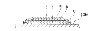
本発明を適用したガスボンベ1では、GFRP層5bと透明樹脂層6との間にRFIDタグ4を配置している。具体的に、このRFIDタグ4は、図5に示すように、GFRP層5bの表面に、磁性体シート7の磁性体粘着層7b及び合成紙8bの余白部分8cを貼着した後、その上を透明樹脂層6(図5において図示せず。)が覆うことによって、被覆層3(図5において図示せず。)に埋設した状態でボンベ本体2に取り付けられている。
In the
この場合、RFIDタグ4を透明樹脂層6により保護すると共に、RFIDタグ4の剥離防止及び防水を行うことが可能である。また、透明樹脂層6を透してRFIDタグ4の視認性を確保できる。さらに、このRFIDタグ4自体の見映えも良くすることが可能である。
In this case, the RFID tag 4 can be protected by the
また、このガスボンベ1では、RFIDタグ4に対して情報の書き込み及び読み出しを行うリーダ/ライタとの通信距離を透明樹脂層6の厚みに相当する距離まで短くできるため、このRFIDタグ4とリーダ/ライタとの間で情報のやり取りを安定して行うことが可能である。すなわち、信頼性の高いガスボンベ1に関する情報の管理を行うことが可能である。
Moreover, in this
また、このガスボンベ1では、透明樹脂層6を剥離するだけでRFIDタグ4の交換を容易に行うことができ、ボンベ本体2も繰り返し使用できることから、コスト上昇を抑えることが可能である。
Moreover, in this
ところで、上記合成紙8a,8bの余白部分8cについては、1〜2mm(本実施形態では約2mm)程度確保することが好ましい。これにより、RFIDタグ4を構成する各層の厚みによる段差を緩和し、GFRP層5bと透明樹脂層6との密着性を確保することが可能となる。また、透明樹脂層6の表面に凹凸や皺等が発生しにくくなり、被覆層3の最表面を滑らかに仕上げて見映えを良くすることができる。
By the way, it is preferable to secure about 1 to 2 mm (about 2 mm in the present embodiment) for the
RFIDタグ4は、上記図4に示す構成に限らず、例えば図6に示すように、合成紙8a,8bの余白部分8cに切れ込み12が設けられた構成としてもよい。ボンベ本体2の胴部2bは曲面からなることから、このような切れ込み12を設けることによって、合成紙8a,8bの余白部分8cをGFRP層5bの表面に貼着したときに、この余白部分8cに入り込む空気を切れ込み12から抜き出し、皺等が寄ったりすることを防止することができる。このような切れ込み12は、皺等が寄り易い部分に設けることが好ましく、例えば合成紙8a,8bの角部や端縁中央部などに設けることが好ましい。
The RFID tag 4 is not limited to the configuration shown in FIG. 4, and may have a configuration in which a
また、RFIDタグ4は、上記図4に示す構成に限らず、例えば図7に示すように、合成紙8a,8bの角部に面取り部13を設けた構成としてもよい。このような面取り部13を合成紙8a,8bの角部に設けることによって、RFIDタグ4が剥がれたりすることを防止することができる。
Further, the RFID tag 4 is not limited to the configuration shown in FIG. 4, and may have a configuration in which chamfered
ガスボンベ1は、図1に示すように、ボンベ本体2の底部2aを収納しながら、このボンベ本体2を起立した状態で保持するカップ状のスカート20を備えた構成であってもよい。この場合、RFIDタグ4は、ボンベ本体2の胴部2bのうち、スカート20によって隠れる位置に配置することが好ましい。また、スカート20は、磁界を通すプラスチック材料からなることが好ましく、これによって、RFIDタグ4は、スカート20越しにリーダ/ライタによって情報の書き込み及び読み出しを行うことが可能となる。
As shown in FIG. 1, the
1…ガスボンベ 2…ボンベ本体(アルミライナー) 3…被覆層 4…RFIDタグ 5a…炭素繊維強化プラスチック(CFRP)層 5b…ガラス繊維強化プラスチック(GFRP)層 6…透明樹脂層 7…磁性体シート 8a,8b…合成紙(ユポ紙) 9…インレット 12…切れ込み 13…面取り部 20…スカート
DESCRIPTION OF
Claims (8)
前記ボンベ本体の表面を覆う被覆層と、
前記被覆層に埋設されたRFIDタグとを備え、
前記被覆層は、繊維強化プラスチック層と透明樹脂層とを順に積層した構造を有し、
前記RFIDタグは、前記繊維強化プラスチック層と前記透明樹脂層との間に配置されていることを特徴とするガスボンベ。 A cylinder body filled with high-pressure gas;
A coating layer covering the surface of the cylinder body;
An RFID tag embedded in the coating layer,
The coating layer has a structure in which a fiber-reinforced plastic layer and a transparent resin layer are laminated in order,
The gas tag according to claim 1, wherein the RFID tag is disposed between the fiber reinforced plastic layer and the transparent resin layer.
前記RFIDタグは、前記ボンベ本体の胴部のうち、前記スカートによって隠れる位置に配置されていることを特徴とする請求項1〜5の何れか一項に記載のガスボンベ。 A skirt that holds the cylinder body in an upright state while storing the bottom of the cylinder body,
6. The gas cylinder according to claim 1, wherein the RFID tag is disposed in a position hidden by the skirt in a body portion of the cylinder main body.
前記RFIDタグは、前記スカート越しにリーダ/ライタによって情報の書き込み及び読み出しを行うことが可能であることを特徴とする請求項6に記載のガスボンベ。 The skirt is made of a plastic material that passes a magnetic field,
7. The gas cylinder according to claim 6, wherein the RFID tag can write and read information by a reader / writer through the skirt.
Priority Applications (2)
| Application Number | Priority Date | Filing Date | Title |
|---|---|---|---|
| JP2010220933A JP2012077780A (en) | 2010-09-30 | 2010-09-30 | Gas cylinder |
| CN2011102995449A CN102444782A (en) | 2010-09-30 | 2011-09-28 | cylinder |
Applications Claiming Priority (1)
| Application Number | Priority Date | Filing Date | Title |
|---|---|---|---|
| JP2010220933A JP2012077780A (en) | 2010-09-30 | 2010-09-30 | Gas cylinder |
Publications (1)
| Publication Number | Publication Date |
|---|---|
| JP2012077780A true JP2012077780A (en) | 2012-04-19 |
Family
ID=46007554
Family Applications (1)
| Application Number | Title | Priority Date | Filing Date |
|---|---|---|---|
| JP2010220933A Pending JP2012077780A (en) | 2010-09-30 | 2010-09-30 | Gas cylinder |
Country Status (2)
| Country | Link |
|---|---|
| JP (1) | JP2012077780A (en) |
| CN (1) | CN102444782A (en) |
Cited By (5)
| Publication number | Priority date | Publication date | Assignee | Title |
|---|---|---|---|---|
| JP2014076197A (en) * | 2012-10-11 | 2014-05-01 | Teikoku Sen I Co Ltd | Air respirator cylinder for fire brigade |
| JP2015121282A (en) * | 2013-12-24 | 2015-07-02 | 本田技研工業株式会社 | Fuel filling method for fuel cell vehicle or fuel filling system for fuel cell vehicle |
| WO2016064626A1 (en) * | 2014-10-24 | 2016-04-28 | Quantum Fuel Systems Technologies Worldwide, Inc. | Composite pressure tank identification and tracking |
| KR101948271B1 (en) * | 2018-04-24 | 2019-05-02 | 주식회사 대흥정공 | A pneumatic tank |
| US10632836B2 (en) | 2017-04-07 | 2020-04-28 | Toyota Jidosha Kabushiki Kaisha | Tank manufacturing method and tank |
Citations (6)
| Publication number | Priority date | Publication date | Assignee | Title |
|---|---|---|---|---|
| JPS61172298U (en) * | 1985-04-15 | 1986-10-25 | ||
| JPS63115698U (en) * | 1987-01-22 | 1988-07-26 | ||
| JP2003014192A (en) * | 2001-07-03 | 2003-01-15 | Asahi Seisakusho Co Ltd | Label integrated type high-pressure gas cylinder |
| JP2006301900A (en) * | 2005-04-20 | 2006-11-02 | Dainippon Printing Co Ltd | Non-contact IC tag label |
| JP2006327637A (en) * | 2005-05-27 | 2006-12-07 | Fuji Seal International Inc | Container with ic tag, and packaging body with ic tag |
| JP2007102513A (en) * | 2005-10-05 | 2007-04-19 | Dainippon Printing Co Ltd | Non-contact IC tag label |
Family Cites Families (5)
| Publication number | Priority date | Publication date | Assignee | Title |
|---|---|---|---|---|
| JP2002181296A (en) * | 2000-12-12 | 2002-06-26 | Hanex Co Ltd | Mounting structure of rfid tag and mounting method of rfid tag |
| JP4790312B2 (en) * | 2005-05-27 | 2011-10-12 | 株式会社フジシールインターナショナル | Container with IC tag and package with IC tag |
| JP3961543B2 (en) * | 2005-07-01 | 2007-08-22 | 株式会社同栄 | Gas cylinder |
| JP4882361B2 (en) * | 2005-12-13 | 2012-02-22 | 大日本印刷株式会社 | Label-type non-contact type data carrier device and manufacturing method thereof |
| JP2008094804A (en) * | 2006-10-16 | 2008-04-24 | Daiichi Sankyo Healthcare Co Ltd | Plaster and its manufacturing method |
-
2010
- 2010-09-30 JP JP2010220933A patent/JP2012077780A/en active Pending
-
2011
- 2011-09-28 CN CN2011102995449A patent/CN102444782A/en active Pending
Patent Citations (6)
| Publication number | Priority date | Publication date | Assignee | Title |
|---|---|---|---|---|
| JPS61172298U (en) * | 1985-04-15 | 1986-10-25 | ||
| JPS63115698U (en) * | 1987-01-22 | 1988-07-26 | ||
| JP2003014192A (en) * | 2001-07-03 | 2003-01-15 | Asahi Seisakusho Co Ltd | Label integrated type high-pressure gas cylinder |
| JP2006301900A (en) * | 2005-04-20 | 2006-11-02 | Dainippon Printing Co Ltd | Non-contact IC tag label |
| JP2006327637A (en) * | 2005-05-27 | 2006-12-07 | Fuji Seal International Inc | Container with ic tag, and packaging body with ic tag |
| JP2007102513A (en) * | 2005-10-05 | 2007-04-19 | Dainippon Printing Co Ltd | Non-contact IC tag label |
Cited By (10)
| Publication number | Priority date | Publication date | Assignee | Title |
|---|---|---|---|---|
| JP2014076197A (en) * | 2012-10-11 | 2014-05-01 | Teikoku Sen I Co Ltd | Air respirator cylinder for fire brigade |
| JP2015121282A (en) * | 2013-12-24 | 2015-07-02 | 本田技研工業株式会社 | Fuel filling method for fuel cell vehicle or fuel filling system for fuel cell vehicle |
| WO2016064626A1 (en) * | 2014-10-24 | 2016-04-28 | Quantum Fuel Systems Technologies Worldwide, Inc. | Composite pressure tank identification and tracking |
| US9534738B2 (en) | 2014-10-24 | 2017-01-03 | Quantum Fuel Systems Llc | Composite pressure tank identification and tracking |
| JP2017533394A (en) * | 2014-10-24 | 2017-11-09 | クォンタム フューエル システムズ エルエルシー | Complex pressure tank identification and tracking |
| EP3209926A4 (en) * | 2014-10-24 | 2017-12-13 | Quantum Fuel Systems LLC | Composite pressure tank identification and tracking |
| US10181064B2 (en) | 2014-10-24 | 2019-01-15 | Quantum Fuel Systems Llc | Composite pressure tank identification and tracking |
| US10632836B2 (en) | 2017-04-07 | 2020-04-28 | Toyota Jidosha Kabushiki Kaisha | Tank manufacturing method and tank |
| US11104219B2 (en) | 2017-04-07 | 2021-08-31 | Toyota Jidosha Kabushiki Kaisha | Tank manufacturing method and tank |
| KR101948271B1 (en) * | 2018-04-24 | 2019-05-02 | 주식회사 대흥정공 | A pneumatic tank |
Also Published As
| Publication number | Publication date |
|---|---|
| CN102444782A (en) | 2012-05-09 |
Similar Documents
| Publication | Publication Date | Title |
|---|---|---|
| JP2012077780A (en) | Gas cylinder | |
| EP3346422A1 (en) | Plastic key fob with full-colour printing and a built-in rfid tag | |
| US20100148928A1 (en) | Payment skin with contactless chip | |
| US10021857B2 (en) | Ear tag for livestock and method for producing an ear tag for livestock | |
| US8640962B2 (en) | Radiofrequency identification device and method for producing said device | |
| US20100032437A1 (en) | Container with Transponder | |
| AU2016414197B2 (en) | Ear tag for livestock and method for producing an ear tag for livestock | |
| US20140191851A1 (en) | Near field communication enabled permanent rfid luggage tag | |
| US8393547B2 (en) | RF proximity financial transaction card having metallic foil layer(s) | |
| US20110133904A1 (en) | Permanent rfid luggage tag with security features | |
| CN202916857U (en) | Alcohol composite anti-counterfeit label based on electronic label and two-dimensional code | |
| US8505825B2 (en) | Layered composite for a card body and method for producing the layered composite | |
| US20230385590A1 (en) | Transaction card with partial glass layer | |
| JP2002181296A (en) | Mounting structure of rfid tag and mounting method of rfid tag | |
| US8448869B2 (en) | Microcircuit card in several parts | |
| JP5023692B2 (en) | IC tag base material and IC tag provided with this IC tag base material | |
| WO2006054508A1 (en) | Data carrier installation body and method of producing the same | |
| JP4872238B2 (en) | IC tag compatible plastic material, IC tag and IC tag compatible container | |
| JP2005170389A (en) | Metal container with RFID tag | |
| CN206615565U (en) | Sealed membrane packing box | |
| JP2006294016A (en) | Electromagnetic wave shielding sheet for card or brochure case | |
| CN222189897U (en) | A thickened smart label | |
| JP2010039691A (en) | Rfid tag reading device and rfid management system | |
| KR101731730B1 (en) | Label using electronic tag sheet | |
| CN205670337U (en) | Can the paper currency sorting thermomechanical components of print transaction information Quick Response Code |
Legal Events
| Date | Code | Title | Description |
|---|---|---|---|
| A621 | Written request for application examination |
Free format text: JAPANESE INTERMEDIATE CODE: A621 Effective date: 20130705 |
|
| A977 | Report on retrieval |
Free format text: JAPANESE INTERMEDIATE CODE: A971007 Effective date: 20140207 |
|
| A131 | Notification of reasons for refusal |
Free format text: JAPANESE INTERMEDIATE CODE: A131 Effective date: 20140304 |
|
| A02 | Decision of refusal |
Free format text: JAPANESE INTERMEDIATE CODE: A02 Effective date: 20140701 |