JP2012027498A - Wideband audio transmission system - Google Patents
Wideband audio transmission system Download PDFInfo
- Publication number
- JP2012027498A JP2012027498A JP2011231780A JP2011231780A JP2012027498A JP 2012027498 A JP2012027498 A JP 2012027498A JP 2011231780 A JP2011231780 A JP 2011231780A JP 2011231780 A JP2011231780 A JP 2011231780A JP 2012027498 A JP2012027498 A JP 2012027498A
- Authority
- JP
- Japan
- Prior art keywords
- signal
- frequency band
- high frequency
- reconstructed
- low frequency
- Prior art date
- Legal status (The legal status is an assumption and is not a legal conclusion. Google has not performed a legal analysis and makes no representation as to the accuracy of the status listed.)
- Pending
Links
Images


Classifications
-
- H—ELECTRICITY
- H04—ELECTRIC COMMUNICATION TECHNIQUE
- H04B—TRANSMISSION
- H04B1/00—Details of transmission systems, not covered by a single one of groups H04B3/00 - H04B13/00; Details of transmission systems not characterised by the medium used for transmission
- H04B1/02—Transmitters
- H04B1/04—Circuits
-
- G—PHYSICS
- G10—MUSICAL INSTRUMENTS; ACOUSTICS
- G10L—SPEECH ANALYSIS TECHNIQUES OR SPEECH SYNTHESIS; SPEECH RECOGNITION; SPEECH OR VOICE PROCESSING TECHNIQUES; SPEECH OR AUDIO CODING OR DECODING
- G10L19/00—Speech or audio signals analysis-synthesis techniques for redundancy reduction, e.g. in vocoders; Coding or decoding of speech or audio signals, using source filter models or psychoacoustic analysis
- G10L19/02—Speech or audio signals analysis-synthesis techniques for redundancy reduction, e.g. in vocoders; Coding or decoding of speech or audio signals, using source filter models or psychoacoustic analysis using spectral analysis, e.g. transform vocoders or subband vocoders
- G10L19/0204—Speech or audio signals analysis-synthesis techniques for redundancy reduction, e.g. in vocoders; Coding or decoding of speech or audio signals, using source filter models or psychoacoustic analysis using spectral analysis, e.g. transform vocoders or subband vocoders using subband decomposition
- G10L19/0208—Subband vocoders
Landscapes
- Engineering & Computer Science (AREA)
- Physics & Mathematics (AREA)
- Signal Processing (AREA)
- Audiology, Speech & Language Pathology (AREA)
- Computational Linguistics (AREA)
- Health & Medical Sciences (AREA)
- Spectroscopy & Molecular Physics (AREA)
- Human Computer Interaction (AREA)
- Acoustics & Sound (AREA)
- Multimedia (AREA)
- Computer Networks & Wireless Communication (AREA)
- Compression, Expansion, Code Conversion, And Decoders (AREA)
- Transmission Systems Not Characterized By The Medium Used For Transmission (AREA)
Abstract
【課題】必要な計算量が減少されるオーディオ伝送システムを提供すること。
【解決手段】本発明のオーディオ伝送システムでは、送信器内で入力信号は2つのスペクトル部分に分割され、それぞれ独自の符号化器によって符号化される。低周波数の信号部分は、通常の狭帯域符号化器によって、高周波数の部分は、LPC符号及び信号増幅符号を出力する符号化器を使用し符号化される。受信器において低周波数の信号部分は、狭帯域復号器を使用することによって、高周波数の部分は、白色雑音信号に高域通過フィルタを施し送信器からのLPC符号によって制御されるLPCフィルタをフィルタが施された白色雑音信号に対しフィルタを施し、送信器の増幅符号を使用し制御される増幅器によって振幅を調節することによって再構成される。再構成された低周波数の信号と高周波数の信号は組み合わされ、両方の周波数帯域を有する出力信号に再構成される。
【選択図】図1An audio transmission system in which a required amount of calculation is reduced is provided.
In the audio transmission system of the present invention, an input signal is divided into two spectral parts in a transmitter, and each is encoded by a unique encoder. The low frequency signal portion is encoded by a normal narrowband encoder, and the high frequency portion is encoded using an encoder that outputs an LPC code and a signal amplification code. The low frequency signal portion at the receiver uses a narrowband decoder, and the high frequency portion filters the white noise signal with a high pass filter and filters the LPC filter controlled by the LPC code from the transmitter. Is reconstructed by filtering the white noise signal subjected to and adjusting the amplitude by an amplifier controlled using the transmitter's amplification code. The reconstructed low frequency signal and high frequency signal are combined and reconstructed into an output signal having both frequency bands.
[Selection] Figure 1
Description
本発明は、伝送信号を、低周波数帯域を有する信号と高周波数帯域を有する信号とに分割する分波器と、低周波数帯域を有する信号から低周波数帯域を有する符号化された信号を発生させ、低周波数帯域を有する符号化された信号を第1の伝送チャネルによって受信器に送信するよう構成される第1の符号化装置と、高周波数帯域を有する信号から高周波数帯域を有する符号化された信号を発生させ、高周波数帯域を有する符号化された信号を第2の伝送チャネルによって送信器から受信器に送信するよう構成される第2の符号化装置とを含む送信器と、低周波数帯域を有する符号化された信号に基づいて低周波数帯域を有する再構成された信号を形成する第1の復号器と、雑音信号源から入来する雑音信号を使用し高周波数帯域を有する符号化された信号に基づいて高周波数帯域を有する再構成された信号を形成する第2の復号器と、低周波数帯域を有する再構成された信号と高周波数帯域を有する再構成された信号とを組み合わせるコンバイナとを含む受信器とを有する伝送システムに関する。 The present invention generates a demultiplexer that divides a transmission signal into a signal having a low frequency band and a signal having a high frequency band, and an encoded signal having a low frequency band from the signal having the low frequency band. A first encoding device configured to transmit an encoded signal having a low frequency band to a receiver via a first transmission channel, and an encoded signal having a high frequency band from a signal having a high frequency band A transmitter comprising: a second encoding device configured to generate an encoded signal and to transmit an encoded signal having a high frequency band from the transmitter to the receiver over a second transmission channel; A first decoder for forming a reconstructed signal having a low frequency band based on an encoded signal having a band; and a code having a high frequency band using a noise signal coming from a noise signal source. A second decoder for forming a reconstructed signal having a high frequency band based on the reconstructed signal, a reconstructed signal having a low frequency band, and a reconstructed signal having a high frequency band The present invention relates to a transmission system having a receiver including a combiner to be combined.
本発明は更に、上述されたような種類の伝送システムに使用されるべき送信器、受信器、符号化装置、復号器、及び符号化方法及び復号化方法に関する。 The invention further relates to a transmitter, a receiver, an encoding device, a decoder, an encoding method and a decoding method to be used in a transmission system of the kind described above.
このような伝送システムは、EP0648024Alから公知である。この特許文書には、入力信号がフィルタバンクによってスペクトル部分に分割されるオーディオ信号用の伝送システムが記載される。これらのスペクトル部分はそれぞれの符号化装置、副符号化器によってそれぞれ符号化される。副符号化器では、信号の包絡線が決められ、この包絡線は多数の基準包絡線と比較される。上記包絡線に最も良好に対応する基準包絡線の識別符号が受信器に送信される。 Such a transmission system is known from EP 0648024 Al. This patent document describes a transmission system for audio signals in which the input signal is divided into spectral parts by a filter bank. These spectral portions are encoded by respective encoding devices and sub-encoders. In the sub-encoder, the envelope of the signal is determined and this envelope is compared with a number of reference envelopes. The reference envelope identification code that best corresponds to the envelope is transmitted to the receiver.
受信器内では、復号器は識別符号に基づいて信号を再構成し、この信号の包絡線は受信した基準包絡線に対応し、その後に包絡線は雑音源から入来する雑音信号によって増大され、その結果、入力信号の再構成されたスペクトル部分が得られる。続いてこれらの再構成されたスペクトル部分は組み合わされ、従って入力信号が再構成される。 Within the receiver, the decoder reconstructs the signal based on the identification code, the envelope of this signal corresponds to the received reference envelope, after which the envelope is augmented by the noise signal coming from the noise source. As a result, a reconstructed spectral portion of the input signal is obtained. These reconstructed spectral parts are then combined, thus reconstructing the input signal.
このような伝送システムの不利点は、送信器内において、符号化装置はフィルタバンクによって入力信号をスペクトル部分に分割し、受信器内においてコンバイナに支援されてスペクトル部分を組み合わせるためにかなりの計算量を有することが必要であることである。 The disadvantage of such a transmission system is that in the transmitter, the coding device divides the input signal into spectral parts by means of a filter bank and in the receiver is assisted by a combiner to combine the spectral parts. It is necessary to have
本発明は、必要な計算量が減少される冒頭部に記載されたような伝送システムを提供することを目的とする。 The invention aims to provide a transmission system as described at the outset in which the required computational complexity is reduced.
このために、本発明の伝送システムでは、第2の符号化装置は、予測係数を決め、受信器に予測係数を送信する分析手段を含み、第2の復号器は、予測係数によって制御されるLPC合成フィルタによって、高周波数帯域を有する信号を再構成する際に雑音信号源から入来する雑音信号にフィルタを施すよう構成されることを特徴とする。 To this end, in the transmission system of the present invention, the second encoding device includes an analysis unit that determines a prediction coefficient and transmits the prediction coefficient to the receiver, and the second decoder is controlled by the prediction coefficient. The LPC synthesis filter is configured to filter a noise signal coming from a noise signal source when reconstructing a signal having a high frequency band.
入力信号は2つの部分に分割され、それにより2つの周波数帯域のそれぞれに対し最適な符号化を選択することが可能である。第1の符号化装置は、関連の有効ビットレートでの低周波数帯域を有する信号に対し効果的である既知の符号化を使用する。このような信号に対し低域通過フィルタが十分である。第2の符号化装置は線形予測符号化(LPC)を使用し、高周波数帯域を有する信号を効率的な方法で符号化する。LPC符号化の特性によって、高域通過フィルタが十分であり、ダウンサンプリングを行う必要がない。高域通過フィルタ及び低域通過フィルタは共にほとんど計算量を必要とせず、更にダウンサンプラは省かれるので、全体としての要求される計算量は減少する。 The input signal is divided into two parts, so that the optimal encoding can be selected for each of the two frequency bands. The first encoder uses a known encoding that is effective for signals having a low frequency band with an associated effective bit rate. A low-pass filter is sufficient for such signals. The second encoding device uses linear predictive coding (LPC) and encodes a signal having a high frequency band in an efficient manner. Due to the characteristics of LPC coding, a high-pass filter is sufficient and there is no need for downsampling. Both the high-pass filter and the low-pass filter require little calculation, and further, the downsampler is omitted, so that the total calculation required is reduced.
高周波数帯域における人間の聴覚システムはかなり正確ではないので、従って、高周波数帯域を有する信号を再構成する際に、白色雑音を信号源としてとらえ、続いて信号源をLPC合成フィルタによってフィルタにかけ、それにより、人間の聴覚システムに対するスペクトルがもともとの信号と十分に一致する信号が得られる。高周波数帯域は、別々に処理されるべき小さな周波数帯域に再分割されることが阻止されるので、要求される計算量は減少する。 The human auditory system in the high frequency band is not quite accurate, so when reconstructing a signal with a high frequency band, white noise is taken as the signal source, and then the signal source is filtered by an LPC synthesis filter, This results in a signal whose spectrum for the human auditory system is sufficiently consistent with the original signal. The high frequency band is prevented from being subdivided into smaller frequency bands that should be processed separately, thus reducing the amount of computation required.
本発明の伝送システムの実施例は、送信器内の第2の符号化装置は、高周波数帯域を有する信号に基づいて増幅符号を発生させるよう構成され、受信器内の第2の復号器は、高周波数帯域を有する信号の再構成の際に増幅符号を使用するよう構成されることを特徴とする。 In an embodiment of the transmission system of the present invention, the second encoding device in the transmitter is configured to generate an amplified code based on a signal having a high frequency band, and the second decoder in the receiver is The amplification code is used when reconstructing a signal having a high frequency band.
符号化装置が増幅符号を決定し、復号器はその増幅符号によって再構成された信号を増幅するので、必要とされる予測係数の数は減少し、それにより、予測係数を決定することは単純化され、少ない計算量が必要とされる。 Since the encoder determines the amplification code and the decoder amplifies the signal reconstructed by that amplification code, the number of required prediction coefficients is reduced, thereby making it simple to determine the prediction coefficients. And a small amount of calculation is required.
周波数帯域は決定されることが可能である。 The frequency band can be determined.
本発明を図面を参照することによって更に説明する。 The invention will be further described by reference to the drawings.
図1に本発明の伝送システムを示す。 FIG. 1 shows a transmission system of the present invention.
入力信号は送信器1の入力19を介し到達する。分波器7は入力信号を、低周波数帯域を有し、第1の符号化器9によって処理される信号と、高周波数帯域を有し、第2の符号化器11によって処理される信号とに分割する。第2の符号化器11はLPC符号化器2及び信号強度計器4を使用する。符号化器11は、高周波数帯域を有する信号の予測係数を決めるLPC符号化器である。符号化された信号は第1の符号化器9及び第2の符号化器11の出力に現れ、伝送チャネル3によって受信器5に送信される。受信器5内では、低周波数帯域を有する符号化された信号は第1の復号器13によって処理され、高周波数帯域を有する符号化された信号は第2の復号器15によって処理され、この復号器15では雑音信号源6、LPC合成フィルタ8、及び増幅器10が使用される。低周波数帯域を有する復号化された信号と高周波数帯域を有する復号化された信号はコンバイナ17によって組み合わされ受信器5の出力21において利用可能な出力信号にされる。
The input signal arrives via the input 19 of the transmitter 1. The
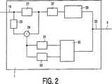
図2は、本発明の送信器の実施例を示す。 FIG. 2 shows an embodiment of the transmitter of the present invention.
入力信号は送信器1の入力19を介し到達する。入力信号は2つのスペクトル部分に分割され、即ち、入力信号が低域通過フィルタ27によって処理されることによって得られる低周波数帯域を有する信号と、低域通過フィルタ27からの低周波数帯域を有する信号と遅延素子25によって遅延される入力信号との差を決定することによって得られる高周波数帯域を有する信号とに分割される。差の信号は、減算器29によって決められる。低域通過フィルタ27は、線形位相特徴を有することが重要である。これは、例えば、低域通過フィルタとして81の長さを有する有限インパルス応答フィルタを使用し、それによりフィルタを通された信号は40サンプルで遅延されることにより達成される。音声に対しては、0乃至3.4kHzの通過帯域周波数と4乃至8kHzの拒絶帯(stop band)とが選択される。遅延素子25は、有限インパルス応答フィルタ内で生じた遅延を補償するよう使用され、それにより減算器29において利用可能である信号は正しい位相関係を有する。
The input signal arrives via the input 19 of the transmitter 1. The input signal is divided into two spectral parts: a signal having a low frequency band obtained by processing the input signal by the
差の信号は次に信号強度計器31に与えられ、信号強度計器31は差の信号の信号強度を測定し、この測定結果に応じて増幅符号を発生させる。この信号強度は、高周波数帯域を有する信号の0.5...10msの長さを有するサブフレームに対し決められる。
The difference signal is then applied to a
ハミング窓(Hamming Window)hによって、信号強度は以下の式に基づいて決められる。

量子化の為に、4つの信号強度は対数定義域に変換される。
li=10log10Pi ただしi=1,2,3,4
For quantization, the four signal strengths are converted to logarithmic domain.
l i = 10 log 10 Pi where i = 1, 2, 3, 4
第1の信号強度l1は4つのビットによって量子化されるのに対し、残りの3つの信号強度l2乃至l4は、3つのビットで前に量子化された信号と相対的に区別をつけて量子化される。 The first signal strength l 1 is quantized by four bits, while the remaining three signal strengths l 2 through l 4 are relatively distinct from the signal previously quantized by three bits. It is quantized.
l1の値は、固定された範囲、例えば16ビットの信号に対し−10乃至60dBの範囲に制限され、4ビットで量子化され、その結果、量子化された信号強度
この差別的な量子化Δiは、例えば−6乃至+6dBmの範囲に制限される。この差別的な量子化を表す指数は
増幅符号は指数
復号器は同様の方法で量子化された信号強度を決める。 The decoder determines the quantized signal strength in a similar manner.
差の信号は更に、LPC符号化器33に与えられる。LPC符号化器33はLPC分析に支援されて差の信号の予測符号を決定する。差の信号に低周波数帯域は無いので、信号のダウンサンプリングは必要ではない。高周波数帯域を有する信号がLPC合成フィルタによって再構成されると、十分に低い振幅レベルを有する周波数特徴が自発的に低周波数帯域内で発生する。6次のLPC分析に支援されて、6つのLPC係数を、高周波数帯域を有する信号の15msのセグメントに対し決定することが可能である。これらの6つのLPC係数を決定するために、セグメントの平均値が決められ、セグメント内のサンプルから差し引かれ、その後、240ドットハミング窓関数が適用される。続いて、レヴィンソン−ダービン再帰が窓信号の自己相関関数に適用される。鋭い共鳴を防ぐために、0.98である拡張係数を使用することが可能である帯域幅拡張が使用される。
The difference signal is further provided to the
6つのLPC係数は、ベクトル量子化の為にラインスペクトル周波数(LSF)ω〔n〕(n=0,1,2...,5)に変換される。量子化されるLSFは、量子化誤差に対する量子化されるLSFの感度に基づく。この感度は、近傍のLSFとの間の距離が減少すると増加する。 The six LPC coefficients are converted to line spectral frequency (LSF) ω [n] (n = 0, 1, 2,..., 5) for vector quantization. The quantized LSF is based on the sensitivity of the quantized LSF to quantization error. This sensitivity increases as the distance between neighboring LSFs decreases.
これは、重み関数Φを使用することにより使用される。
1024の所定の6次のLSFベクトルを含む単一の符号表cは、ベクトル量子化器に対し使用され、LSFベクトルはLBGアルゴリズムを符号表に対し行うことによって得られる。 A single code table c containing 1024 predetermined 6th order LSF vectors is used for the vector quantizer, which is obtained by performing the LBG algorithm on the code table.
符号表cの各素子jに対し、以下の距離の関数(distance function)が評価される。:
最短距離を有する符号表の素子の指数が選択される。このLSF符号表の指数は復号器に送信される。 The index of the code table element with the shortest distance is selected. The index of this LSF code table is transmitted to the decoder.
低域通過フィルタ27から入来する低周波数帯域を有する信号は、ダウンサンプラ37によってダウンサンプリングされ、狭周波数帯符号化器39に与えられる。狭周波数帯符号化器39は、例えばITUのG.729又はG.728に記載されるような低周波数帯域を有する信号に対し最適化された通常の符号化器である。狭周波数帯符号化器39の種類又は動作は本発明の実施に重要ではない。狭周波数帯符号化器39は、信号強度計器31から入来する増幅符号及びLPC符号化器33から入来する符号化された信号と共に、符号化された信号を発生させ、更なる処理の為に送信器1の出力23において利用可能となる。
A signal having a low frequency band coming from the low-
図3は、本発明の受信器の実施例を示す。 FIG. 3 shows an embodiment of the receiver of the present invention.
伝送チャネルの入力48を介し到着する符号化された信号は、狭周波数帯復号器41及び復号器47に与えられ、各復号器は符号化された信号を処理し、更に処理のための増幅符号を処理する。
The encoded signal arriving via the
狭周波数帯復号器41によって、低周波数帯域を有する符号化された信号から低周波数帯域を有する再構成された信号が回収され、その後にアップサンプラ43によってアップサンプリングが行われる。復号化又はアップサンプリングの際に発生する可能性のある高周波数帯域の所望しない信号を阻止するために、アップサンプリングされた後、再構成された信号は低域通過フィルタ45によってフィルタが施される。低域通過フィルタ45は、送信器内の低域通過フィルタ27と匹敵することが可能な周波数特徴を有する。
The narrow
高周波数帯域を有する符号化された信号及び増幅符号は、復号器47によって、再構成された信号の周波数特徴及び信号強度を適応することが可能であるLPC合成フィルタ55及び増幅器53用の制御信号に変換される。
Control signals for the LPC synthesis filter 55 and the
雑音源49は、白色雑音信号を発生する。白色雑音信号は、80サンプルの長さの雑音セグメントを含み、これは、均一なランダムパルス分布を有するランダムパルス発生器によって発生される。この雑音信号は、3500Hzの遮断周波数を有する6次の無限インパルス応答高域通過フィルタ51によって処理され、それにより高周波数帯域を有する信号の周波数帯域に匹敵する周波数帯域を有するフィルタが施された雑音信号が得られる。
The
高域通過フィルタ51から入来するフィルタが施された雑音信号の振幅スペクトルは、LPC合成フィルタ55によって高周波数帯域を有する信号の振幅スペクトルに適応される。LPCフィルタ55を設定するために必要なLPCパラメータは、受信したLPC符号表の指数に支援されて符号表から正しいLSFを選択し、これらのLSFをLPCパラメータに変換することにより得られる。
The amplitude spectrum of the filtered noise signal coming from the high-
LPC合成フィルタによって高周波数帯域を有する信号に再構成する際に、十分に低い振幅レベルを有する振幅スペクトルは自発的に低周波数帯域に発生する。 When reconstructing a signal having a high frequency band by the LPC synthesis filter, an amplitude spectrum having a sufficiently low amplitude level is spontaneously generated in the low frequency band.
LPC合成フィルタ55から入来するフィルタが施された雑音信号は、受信した増幅符号内の指数に設定される増幅器53によって増幅される。これにより、高周波数帯域を有する再構成された信号の信号強度が、高周波数帯域を有する信号の信号強度に適応することが達成される。信号強度は、受信した指数
フィルタが施された雑音信号は5msのサブフレームに再分割される。各サブフレームs'に対し信号強度が決められる:
サブフレームIに対する基準倍率giは以下のように決められる。
雑音信号のセグメントは基準倍率がかけられ、つまり、基準倍率giによって増幅され、オーバラップと共に組み合わされ高周波数の再構成された信号を形成する。 Segment of the noise signal reference magnification is multiplied, in other words, is amplified by the scale factor g i, is combined with overlap to form a reconstructed signal of higher frequency.
高周波数帯域を有する信号と低周波数帯域を有する信号の再構成の際に様々な信号遅延が発生することが可能であるので、増幅器53から入来する信号を遅延させるための遅延素子59が設けられる。低周波数帯域を有する信号が、高周波数帯域を有する信号より少ない遅延を有する場合、遅延素子59は低域通過フィルタ45とコンバイナ57との間に挿入されることもある。
Since various signal delays can occur when reconfiguring a signal having a high frequency band and a signal having a low frequency band, a
低域通過フィルタ45から入来する低周波数帯域を有する再構成された信号と、遅延素子59から入来する高周波数帯域を有する再構成された信号は、コンバイナ57によって組み合わされ、受信器の出力21において利用可能である出力信号にされる。低周波数帯域を有する再構成された信号と高周波数帯域を有する再構成された信号の周波数特徴はほとんど重ならないので、2つの再構成された信号を単純に加算することによって完全な周波数帯域を有する出力信号を得ることが可能である。
The reconstructed signal having a low frequency band coming from the low-
Claims (6)
上記低周波数帯域を有する符号化された信号に基づいて低周波数帯域を有する再構成された信号を形成する第1の復号器と、雑音信号源から入来する雑音信号を使用し上記高周波数帯域を有する符号化された信号に基づいて高周波数帯域を有する再構成された信号を形成する第2の復号器と、上記低周波数帯域を有する再構成された信号と上記高周波数帯域を有する再構成された信号とを組み合わせるコンバイナとを含む受信器とを有する伝送システムであって、
上記第2の符号化装置は、予測係数を決め、上記受信器に上記予測係数を送信する分析手段を有し、
上記第2の復号器は、上記予測係数によって制御されるLPC合成フィルタによって、上記高周波数帯域を有する信号を再構成する際に上記雑音信号源から入来する上記雑音信号にフィルタを施すよう構成され、
上記雑音信号源は、白色雑音源であり、上記雑音信号は、白色雑音信号であることを特徴とする伝送システム。 A demultiplexer that divides a transmission signal into a signal having a low frequency band and a signal having a high frequency band; and generating a coded signal having a low frequency band from the signal having the low frequency band, and A first encoding device configured to transmit an encoded signal having a frequency band to a receiver via a first transmission channel, and an encoded signal having a high frequency band from the signal having the high frequency band; A transmitter comprising: a second encoding device configured to generate a signal and to transmit the encoded signal having the high frequency band from the transmitter to the receiver via a second transmission channel;
A first decoder for forming a reconstructed signal having a low frequency band based on the encoded signal having the low frequency band; and using the noise signal coming from a noise signal source, the high frequency band A second decoder for forming a reconstructed signal having a high frequency band based on an encoded signal having: a reconstructed signal having the low frequency band; and a reconstruction having the high frequency band And a receiver including a combiner for combining the generated signals,
The second encoding device includes an analysis unit that determines a prediction coefficient and transmits the prediction coefficient to the receiver.
The second decoder is configured to filter the noise signal coming from the noise signal source when the signal having the high frequency band is reconstructed by the LPC synthesis filter controlled by the prediction coefficient. And
The transmission system, wherein the noise signal source is a white noise source, and the noise signal is a white noise signal.
上記受信器内の上記第2の復号器は、上記高周波数帯域を有する信号の再構成の際に上記増幅符号を使用するよう構成されることを特徴とする請求項1記載の伝送システム。 The second encoding device in the transmitter is configured to generate an amplified code based on a signal having the high frequency band;
The transmission system according to claim 1, wherein the second decoder in the receiver is configured to use the amplification code when reconstructing the signal having the high frequency band.
上記第2の復号器は、予測係数によって制御されるLPC合成フィルタによって、高周波数帯域を有する信号を再構成する際に上記雑音信号源から入来する上記雑音信号にフィルタを施すよう構成され、
上記雑音信号源は、白色雑音源であり、上記雑音信号は、白色雑音信号であることを特徴とする受信器。 A first decoder for forming a reconstructed signal having a low frequency band based on an encoded signal having a low frequency band, and having a high frequency band using a noise signal coming from a noise signal source A second decoder for forming a reconstructed signal having a high frequency band based on the encoded signal; a reconstructed signal having the low frequency band; and a reconstructed signal having the high frequency band A receiver including a combiner for combining signals,
The second decoder is configured to filter the noise signal coming from the noise signal source when reconstructing a signal having a high frequency band by an LPC synthesis filter controlled by a prediction coefficient,
The receiver, wherein the noise signal source is a white noise source, and the noise signal is a white noise signal.
上記第2の復号器は、予測係数によって制御されるLPC合成フィルタによって、高周波数帯域を有する信号を再構成する際に上記雑音信号源から入来する上記雑音信号にフィルタを施すよう構成され、
上記雑音信号源は、白色雑音源であり、上記雑音信号は、白色雑音信号であることを特徴とする復号化装置。 A first decoder for forming a reconstructed signal having a low frequency band based on an encoded signal having a low frequency band, and having a high frequency band using a noise signal coming from a noise signal source A second decoder for forming a reconstructed signal having a high frequency band based on the encoded signal; a reconstructed signal having the low frequency band; and a reconstructed signal having the high frequency band A decoding device comprising a combiner for combining signals,
The second decoder is configured to filter the noise signal coming from the noise signal source when reconstructing a signal having a high frequency band by an LPC synthesis filter controlled by a prediction coefficient,
The decoding apparatus according to claim 1, wherein the noise signal source is a white noise source, and the noise signal is a white noise signal.
予測係数によって制御されるLPC合成フィルタによって、高周波数帯域を有する信号を再構成する際に上記雑音信号源から入来する上記雑音信号にフィルタを施し、
上記雑音信号源は、白色雑音源であり、上記雑音信号は、白色雑音信号であることを特徴とする方法。 Form a reconstructed signal having a low frequency band based on an encoded signal having a low frequency band, and use a noise signal coming from a noise signal source to produce an encoded signal having a high frequency band Decoding a coded signal based on which a reconstructed signal having a high frequency band is formed and combining the reconstructed signal having the low frequency band and the reconstructed signal having the high frequency band A method of
Filtering the noise signal coming from the noise signal source when reconstructing a signal having a high frequency band by an LPC synthesis filter controlled by a prediction coefficient;
The method according to claim 1, wherein the noise signal source is a white noise source, and the noise signal is a white noise signal.
Applications Claiming Priority (2)
| Application Number | Priority Date | Filing Date | Title |
|---|---|---|---|
| EP99203819.0 | 1999-11-16 | ||
| EP99203819 | 1999-11-16 |
Related Parent Applications (1)
| Application Number | Title | Priority Date | Filing Date |
|---|---|---|---|
| JP2001537725A Division JP5220254B2 (en) | 1999-11-16 | 2000-10-19 | Wideband audio transmission system |
Publications (1)
| Publication Number | Publication Date |
|---|---|
| JP2012027498A true JP2012027498A (en) | 2012-02-09 |
Family
ID=8240869
Family Applications (2)
| Application Number | Title | Priority Date | Filing Date |
|---|---|---|---|
| JP2001537725A Expired - Lifetime JP5220254B2 (en) | 1999-11-16 | 2000-10-19 | Wideband audio transmission system |
| JP2011231780A Pending JP2012027498A (en) | 1999-11-16 | 2011-10-21 | Wideband audio transmission system |
Family Applications Before (1)
| Application Number | Title | Priority Date | Filing Date |
|---|---|---|---|
| JP2001537725A Expired - Lifetime JP5220254B2 (en) | 1999-11-16 | 2000-10-19 | Wideband audio transmission system |
Country Status (7)
| Country | Link |
|---|---|
| US (1) | US6772114B1 (en) |
| EP (1) | EP1147514B1 (en) |
| JP (2) | JP5220254B2 (en) |
| KR (1) | KR100675309B1 (en) |
| CN (1) | CN1192355C (en) |
| DE (1) | DE60019268T2 (en) |
| WO (1) | WO2001037263A1 (en) |
Cited By (2)
| Publication number | Priority date | Publication date | Assignee | Title |
|---|---|---|---|---|
| RU2649940C2 (en) * | 2013-07-22 | 2018-04-05 | Фраунхофер-Гезелльшафт Цур Фердерунг Дер Ангевандтен Форшунг Е.Ф. | Apparatus and method for decoding or encoding an audio signal using energy information values for a reconstruction band |
| US12112765B2 (en) | 2015-03-09 | 2024-10-08 | Fraunhofer-Gesellschaft Zur Foerderung Der Angewandten Forschung E.V. | Audio encoder, audio decoder, method for encoding an audio signal and method for decoding an encoded audio signal |
Families Citing this family (57)
| Publication number | Priority date | Publication date | Assignee | Title |
|---|---|---|---|---|
| KR100675309B1 (en) * | 1999-11-16 | 2007-01-29 | 코닌클리케 필립스 일렉트로닉스 엔.브이. | Wideband audio transmission system, transmitter, receiver, coding device, decoding device and coding method and decoding method for use in the transmission system |
| SE0004163D0 (en) * | 2000-11-14 | 2000-11-14 | Coding Technologies Sweden Ab | Enhancing perceptual performance or high frequency reconstruction coding methods by adaptive filtering |
| SE0202159D0 (en) | 2001-07-10 | 2002-07-09 | Coding Technologies Sweden Ab | Efficientand scalable parametric stereo coding for low bitrate applications |
| US8605911B2 (en) | 2001-07-10 | 2013-12-10 | Dolby International Ab | Efficient and scalable parametric stereo coding for low bitrate audio coding applications |
| DE60202881T2 (en) * | 2001-11-29 | 2006-01-19 | Coding Technologies Ab | RECONSTRUCTION OF HIGH-FREQUENCY COMPONENTS |
| SE0202770D0 (en) | 2002-09-18 | 2002-09-18 | Coding Technologies Sweden Ab | Method of reduction of aliasing is introduced by spectral envelope adjustment in real-valued filterbanks |
| KR100917464B1 (en) * | 2003-03-07 | 2009-09-14 | 삼성전자주식회사 | Encoding method, apparatus, decoding method and apparatus for digital data using band extension technique |
| GB2403634B (en) * | 2003-06-30 | 2006-11-29 | Nokia Corp | An audio encoder |
| US10848118B2 (en) | 2004-08-10 | 2020-11-24 | Bongiovi Acoustics Llc | System and method for digital signal processing |
| US9413321B2 (en) | 2004-08-10 | 2016-08-09 | Bongiovi Acoustics Llc | System and method for digital signal processing |
| US9281794B1 (en) | 2004-08-10 | 2016-03-08 | Bongiovi Acoustics Llc. | System and method for digital signal processing |
| US11431312B2 (en) | 2004-08-10 | 2022-08-30 | Bongiovi Acoustics Llc | System and method for digital signal processing |
| US10158337B2 (en) | 2004-08-10 | 2018-12-18 | Bongiovi Acoustics Llc | System and method for digital signal processing |
| US8284955B2 (en) | 2006-02-07 | 2012-10-09 | Bongiovi Acoustics Llc | System and method for digital signal processing |
| KR100707186B1 (en) * | 2005-03-24 | 2007-04-13 | 삼성전자주식회사 | Audio encoding and decoding apparatus, method and recording medium |
| CN100471077C (en) * | 2005-03-25 | 2009-03-18 | 嘉藤电气股份有限公司 | Frequency-selecting remote-control calling machine |
| BRPI0608270A2 (en) | 2005-04-01 | 2009-10-06 | Qualcomm Inc | anti-dispersion filtration systems, methods and equipment |
| UA94041C2 (en) * | 2005-04-01 | 2011-04-11 | Квелкомм Инкорпорейтед | Method and device for anti-sparseness filtering |
| CN101199003B (en) * | 2005-04-22 | 2012-01-11 | 高通股份有限公司 | Systems, methods, and apparatus for gain factor attenuation |
| US7944995B2 (en) * | 2005-11-14 | 2011-05-17 | Telefonaktiebolaget Lm Ericsson (Publ) | Variable bandwidth receiver |
| US8417185B2 (en) | 2005-12-16 | 2013-04-09 | Vocollect, Inc. | Wireless headset and method for robust voice data communication |
| US7773767B2 (en) | 2006-02-06 | 2010-08-10 | Vocollect, Inc. | Headset terminal with rear stability strap |
| US7885419B2 (en) | 2006-02-06 | 2011-02-08 | Vocollect, Inc. | Headset terminal with speech functionality |
| US9195433B2 (en) | 2006-02-07 | 2015-11-24 | Bongiovi Acoustics Llc | In-line signal processor |
| US9348904B2 (en) | 2006-02-07 | 2016-05-24 | Bongiovi Acoustics Llc. | System and method for digital signal processing |
| US11202161B2 (en) | 2006-02-07 | 2021-12-14 | Bongiovi Acoustics Llc | System, method, and apparatus for generating and digitally processing a head related audio transfer function |
| US9615189B2 (en) | 2014-08-08 | 2017-04-04 | Bongiovi Acoustics Llc | Artificial ear apparatus and associated methods for generating a head related audio transfer function |
| US10069471B2 (en) | 2006-02-07 | 2018-09-04 | Bongiovi Acoustics Llc | System and method for digital signal processing |
| US10848867B2 (en) | 2006-02-07 | 2020-11-24 | Bongiovi Acoustics Llc | System and method for digital signal processing |
| US10701505B2 (en) | 2006-02-07 | 2020-06-30 | Bongiovi Acoustics Llc. | System, method, and apparatus for generating and digitally processing a head related audio transfer function |
| US7873511B2 (en) * | 2006-06-30 | 2011-01-18 | Fraunhofer-Gesellschaft Zur Foerderung Der Angewandten Forschung E.V. | Audio encoder, audio decoder and audio processor having a dynamically variable warping characteristic |
| KR101565919B1 (en) * | 2006-11-17 | 2015-11-05 | 삼성전자주식회사 | Method and apparatus for encoding and decoding high frequency signal |
| KR101438388B1 (en) | 2006-11-21 | 2014-09-12 | 삼성전자주식회사 | Method and System of Scalable Encoding/Decoding Audio/Speech Signal |
| US8285555B2 (en) * | 2006-11-21 | 2012-10-09 | Samsung Electronics Co., Ltd. | Method, medium, and system scalably encoding/decoding audio/speech |
| KR101379263B1 (en) | 2007-01-12 | 2014-03-28 | 삼성전자주식회사 | Method and apparatus for decoding bandwidth extension |
| EP2144231A1 (en) * | 2008-07-11 | 2010-01-13 | Fraunhofer-Gesellschaft zur Förderung der angewandten Forschung e.V. | Low bitrate audio encoding/decoding scheme with common preprocessing |
| EP2144230A1 (en) * | 2008-07-11 | 2010-01-13 | Fraunhofer-Gesellschaft zur Förderung der angewandten Forschung e.V. | Low bitrate audio encoding/decoding scheme having cascaded switches |
| USD605629S1 (en) | 2008-09-29 | 2009-12-08 | Vocollect, Inc. | Headset |
| PL3992966T3 (en) | 2009-01-16 | 2023-03-20 | Dolby International Ab | HARMONIC TRANSPOSITION EXTENDED BY VECTOR PRODUCT |
| US8160287B2 (en) | 2009-05-22 | 2012-04-17 | Vocollect, Inc. | Headset with adjustable headband |
| US8438659B2 (en) | 2009-11-05 | 2013-05-07 | Vocollect, Inc. | Portable computing device and headset interface |
| CN102263576B (en) * | 2010-05-27 | 2014-06-25 | 盛乐信息技术(上海)有限公司 | Wireless information transmitting method and method realizing device |
| US9344828B2 (en) | 2012-12-21 | 2016-05-17 | Bongiovi Acoustics Llc. | System and method for digital signal processing |
| US9398394B2 (en) | 2013-06-12 | 2016-07-19 | Bongiovi Acoustics Llc | System and method for stereo field enhancement in two-channel audio systems |
| US9883318B2 (en) | 2013-06-12 | 2018-01-30 | Bongiovi Acoustics Llc | System and method for stereo field enhancement in two-channel audio systems |
| US9264004B2 (en) | 2013-06-12 | 2016-02-16 | Bongiovi Acoustics Llc | System and method for narrow bandwidth digital signal processing |
| US9397629B2 (en) | 2013-10-22 | 2016-07-19 | Bongiovi Acoustics Llc | System and method for digital signal processing |
| US9906858B2 (en) | 2013-10-22 | 2018-02-27 | Bongiovi Acoustics Llc | System and method for digital signal processing |
| US10820883B2 (en) | 2014-04-16 | 2020-11-03 | Bongiovi Acoustics Llc | Noise reduction assembly for auscultation of a body |
| US10639000B2 (en) | 2014-04-16 | 2020-05-05 | Bongiovi Acoustics Llc | Device for wide-band auscultation |
| US9615813B2 (en) | 2014-04-16 | 2017-04-11 | Bongiovi Acoustics Llc. | Device for wide-band auscultation |
| US9564146B2 (en) | 2014-08-01 | 2017-02-07 | Bongiovi Acoustics Llc | System and method for digital signal processing in deep diving environment |
| US9638672B2 (en) | 2015-03-06 | 2017-05-02 | Bongiovi Acoustics Llc | System and method for acquiring acoustic information from a resonating body |
| US9621994B1 (en) | 2015-11-16 | 2017-04-11 | Bongiovi Acoustics Llc | Surface acoustic transducer |
| US9906867B2 (en) | 2015-11-16 | 2018-02-27 | Bongiovi Acoustics Llc | Surface acoustic transducer |
| JP2021521700A (en) | 2018-04-11 | 2021-08-26 | ボンジョビ アコースティックス リミテッド ライアビリティー カンパニー | Audio Enhanced Hearing Protection System |
| WO2020028833A1 (en) | 2018-08-02 | 2020-02-06 | Bongiovi Acoustics Llc | System, method, and apparatus for generating and digitally processing a head related audio transfer function |
Citations (4)
| Publication number | Priority date | Publication date | Assignee | Title |
|---|---|---|---|---|
| JPS6370300A (en) * | 1986-09-11 | 1988-03-30 | エイ・ティ・アンド・ティ・コーポレーション | Human voice coding processing system |
| US5774837A (en) * | 1995-09-13 | 1998-06-30 | Voxware, Inc. | Speech coding system and method using voicing probability determination |
| JPH10222195A (en) * | 1996-12-02 | 1998-08-21 | Oki Electric Ind Co Ltd | Coding device, decoding device, coding method, and decoding method for voice signal |
| JP2003514266A (en) * | 1999-11-16 | 2003-04-15 | コーニンクレッカ フィリップス エレクトロニクス エヌ ヴィ | Broadband audio transmission system |
Family Cites Families (7)
| Publication number | Priority date | Publication date | Assignee | Title |
|---|---|---|---|---|
| JPH02272500A (en) * | 1989-04-13 | 1990-11-07 | Fujitsu Ltd | Code driving voice encoding system |
| JP2779886B2 (en) * | 1992-10-05 | 1998-07-23 | 日本電信電話株式会社 | Wideband audio signal restoration method |
| BE1007616A3 (en) * | 1993-10-11 | 1995-08-22 | Philips Electronics Nv | Transmission with simplified source code ring. |
| JPH08102687A (en) * | 1994-09-29 | 1996-04-16 | Yamaha Corp | Aural transmission/reception system |
| US5710863A (en) * | 1995-09-19 | 1998-01-20 | Chen; Juin-Hwey | Speech signal quantization using human auditory models in predictive coding systems |
| US6233550B1 (en) * | 1997-08-29 | 2001-05-15 | The Regents Of The University Of California | Method and apparatus for hybrid coding of speech at 4kbps |
| US6078880A (en) * | 1998-07-13 | 2000-06-20 | Lockheed Martin Corporation | Speech coding system and method including voicing cut off frequency analyzer |
-
2000
- 2000-10-19 KR KR1020017008931A patent/KR100675309B1/en not_active Expired - Lifetime
- 2000-10-19 DE DE60019268T patent/DE60019268T2/en not_active Expired - Lifetime
- 2000-10-19 CN CNB008027587A patent/CN1192355C/en not_active Expired - Lifetime
- 2000-10-19 EP EP00975894A patent/EP1147514B1/en not_active Expired - Lifetime
- 2000-10-19 WO PCT/EP2000/010362 patent/WO2001037263A1/en not_active Ceased
- 2000-10-19 JP JP2001537725A patent/JP5220254B2/en not_active Expired - Lifetime
- 2000-11-13 US US09/710,916 patent/US6772114B1/en not_active Expired - Lifetime
-
2011
- 2011-10-21 JP JP2011231780A patent/JP2012027498A/en active Pending
Patent Citations (4)
| Publication number | Priority date | Publication date | Assignee | Title |
|---|---|---|---|---|
| JPS6370300A (en) * | 1986-09-11 | 1988-03-30 | エイ・ティ・アンド・ティ・コーポレーション | Human voice coding processing system |
| US5774837A (en) * | 1995-09-13 | 1998-06-30 | Voxware, Inc. | Speech coding system and method using voicing probability determination |
| JPH10222195A (en) * | 1996-12-02 | 1998-08-21 | Oki Electric Ind Co Ltd | Coding device, decoding device, coding method, and decoding method for voice signal |
| JP2003514266A (en) * | 1999-11-16 | 2003-04-15 | コーニンクレッカ フィリップス エレクトロニクス エヌ ヴィ | Broadband audio transmission system |
Cited By (26)
| Publication number | Priority date | Publication date | Assignee | Title |
|---|---|---|---|---|
| US10847167B2 (en) | 2013-07-22 | 2020-11-24 | Fraunhofer-Gesellschaft Zur Foerderung Der Angewandten Forschung E.V. | Audio encoder, audio decoder and related methods using two-channel processing within an intelligent gap filling framework |
| US11922956B2 (en) | 2013-07-22 | 2024-03-05 | Fraunhofer-Gesellschaft Zur Foerderung Der Angewandten Forschung E.V. | Apparatus and method for encoding or decoding an audio signal with intelligent gap filling in the spectral domain |
| US10134404B2 (en) | 2013-07-22 | 2018-11-20 | Fraunhofer-Gesellschaft Zur Foerderung Der Angewandten Forschung E.V. | Audio encoder, audio decoder and related methods using two-channel processing within an intelligent gap filling framework |
| US10147430B2 (en) | 2013-07-22 | 2018-12-04 | Fraunhofer-Gesellschaft Zur Foerderung Der Angewandten Forschung E.V. | Apparatus and method for decoding and encoding an audio signal using adaptive spectral tile selection |
| US10276183B2 (en) | 2013-07-22 | 2019-04-30 | Fraunhofer-Gesellschaft Zur Foerderung Der Angewandten Forschung E.V. | Apparatus and method for decoding or encoding an audio signal using energy information values for a reconstruction band |
| US10311892B2 (en) | 2013-07-22 | 2019-06-04 | Fraunhofer-Gesellschaft Zur Foerderung Der Angewandten Forschung E.V. | Apparatus and method for encoding or decoding audio signal with intelligent gap filling in the spectral domain |
| US10332531B2 (en) | 2013-07-22 | 2019-06-25 | Fraunhofer-Gesellschaft Zur Foerderung Der Angewandten Forschung E.V. | Apparatus and method for decoding or encoding an audio signal using energy information values for a reconstruction band |
| US10332539B2 (en) | 2013-07-22 | 2019-06-25 | Fraunhofer-Gesellscheaft zur Foerderung der angewanften Forschung e.V. | Apparatus and method for encoding and decoding an encoded audio signal using temporal noise/patch shaping |
| US10347274B2 (en) | 2013-07-22 | 2019-07-09 | Fraunhofer-Gesellschaft Zur Foerderung Der Angewandten Forschung E.V. | Apparatus and method for encoding and decoding an encoded audio signal using temporal noise/patch shaping |
| US10515652B2 (en) | 2013-07-22 | 2019-12-24 | Fraunhofer-Gesellschaft Zur Foerderung Der Angewandten Forschung E.V. | Apparatus and method for decoding an encoded audio signal using a cross-over filter around a transition frequency |
| US10573334B2 (en) | 2013-07-22 | 2020-02-25 | Fraunhofer-Gesellschaft Zur Foerderung Der Angewandten Forschung E.V. | Apparatus and method for encoding or decoding an audio signal with intelligent gap filling in the spectral domain |
| US10593345B2 (en) | 2013-07-22 | 2020-03-17 | Fraunhofer-Gesellschaft Zur Foerderung Der Angewandten Forschung E.V. | Apparatus for decoding an encoded audio signal with frequency tile adaption |
| US10002621B2 (en) | 2013-07-22 | 2018-06-19 | Fraunhofer-Gesellschaft Zur Foerderung Der Angewandten Forschung E.V. | Apparatus and method for decoding an encoded audio signal using a cross-over filter around a transition frequency |
| RU2649940C2 (en) * | 2013-07-22 | 2018-04-05 | Фраунхофер-Гезелльшафт Цур Фердерунг Дер Ангевандтен Форшунг Е.Ф. | Apparatus and method for decoding or encoding an audio signal using energy information values for a reconstruction band |
| US11289104B2 (en) | 2013-07-22 | 2022-03-29 | Fraunhofer-Gesellschaft Zur Foerderung Der Angewandten Forschung E.V. | Apparatus and method for encoding or decoding an audio signal with intelligent gap filling in the spectral domain |
| US11222643B2 (en) | 2013-07-22 | 2022-01-11 | Fraunhofer-Gesellschaft Zur Foerderung Der Angewandten Forschung E.V. | Apparatus for decoding an encoded audio signal with frequency tile adaption |
| US11250862B2 (en) | 2013-07-22 | 2022-02-15 | Fraunhofer-Gesellschaft Zur Foerderung Der Angewandten Forschung E.V. | Apparatus and method for decoding or encoding an audio signal using energy information values for a reconstruction band |
| US11257505B2 (en) | 2013-07-22 | 2022-02-22 | Fraunhofer-Gesellschaft Zur Foerderung Der Angewandten Forschung E.V. | Audio encoder, audio decoder and related methods using two-channel processing within an intelligent gap filling framework |
| US11049506B2 (en) | 2013-07-22 | 2021-06-29 | Fraunhofer-Gesellschaft Zur Foerderung Der Angewandten Forschung E.V. | Apparatus and method for encoding and decoding an encoded audio signal using temporal noise/patch shaping |
| US11735192B2 (en) | 2013-07-22 | 2023-08-22 | Fraunhofer-Gesellschaft Zur Foerderung Der Angewandten Forschung E.V. | Audio encoder, audio decoder and related methods using two-channel processing within an intelligent gap filling framework |
| US11769512B2 (en) | 2013-07-22 | 2023-09-26 | Fraunhofer-Gesellschaft Zur Foerderung Der Angewandten Forschung E.V. | Apparatus and method for decoding and encoding an audio signal using adaptive spectral tile selection |
| US11769513B2 (en) | 2013-07-22 | 2023-09-26 | Fraunhofer-Gesellschaft Zur Foerderung Der Angewandten Forschung E.V. | Apparatus and method for decoding or encoding an audio signal using energy information values for a reconstruction band |
| US10984805B2 (en) | 2013-07-22 | 2021-04-20 | Fraunhofer-Gesellschaft Zur Foerderung Der Angewandten Forschung E.V. | Apparatus and method for decoding and encoding an audio signal using adaptive spectral tile selection |
| US11996106B2 (en) | 2013-07-22 | 2024-05-28 | Fraunhofer-Gesellschaft Zur Foerderung Der Angewandten Forschung E. V. | Apparatus and method for encoding and decoding an encoded audio signal using temporal noise/patch shaping |
| US12142284B2 (en) | 2013-07-22 | 2024-11-12 | Fraunhofer-Gesellschaft Zur Foerderung Der Angewandten Forschung E.V. | Audio encoder, audio decoder and related methods using two-channel processing within an intelligent gap filling framework |
| US12112765B2 (en) | 2015-03-09 | 2024-10-08 | Fraunhofer-Gesellschaft Zur Foerderung Der Angewandten Forschung E.V. | Audio encoder, audio decoder, method for encoding an audio signal and method for decoding an encoded audio signal |
Also Published As
| Publication number | Publication date |
|---|---|
| EP1147514B1 (en) | 2005-04-06 |
| JP2003514266A (en) | 2003-04-15 |
| WO2001037263A1 (en) | 2001-05-25 |
| DE60019268D1 (en) | 2005-05-12 |
| US6772114B1 (en) | 2004-08-03 |
| JP5220254B2 (en) | 2013-06-26 |
| KR100675309B1 (en) | 2007-01-29 |
| CN1337043A (en) | 2002-02-20 |
| KR20010108099A (en) | 2001-12-07 |
| CN1192355C (en) | 2005-03-09 |
| EP1147514A1 (en) | 2001-10-24 |
| DE60019268T2 (en) | 2006-02-02 |
Similar Documents
| Publication | Publication Date | Title |
|---|---|---|
| JP5220254B2 (en) | Wideband audio transmission system | |
| CN1926610B (en) | Method for synthesizing monophonic audio signal, audio decoder and coding system | |
| US7672837B2 (en) | Method and device for adaptive bandwidth pitch search in coding wideband signals | |
| JP4934427B2 (en) | Speech signal decoding apparatus and speech signal encoding apparatus | |
| EP1157374B1 (en) | Enhancing perceptual performance of sbr and related hfr coding methods by adaptive noise-floor addition and noise substitution limiting | |
| EP1232494B1 (en) | Gain-smoothing in wideband speech and audio signal decoder | |
| KR101484426B1 (en) | Audio signal bandwidth extension in celp-based speech coder | |
| JP4302978B2 (en) | Pseudo high-bandwidth signal estimation system for speech codec | |
| JPH11510274A (en) | Method and apparatus for generating and encoding line spectral square root | |
| KR101452666B1 (en) | Audio signal bandwidth extension in celp-based speech coder | |
| JPH11109994A (en) | Tone encoding apparatus, tone encoding method, and recording medium recording tone encoding program | |
| JP3230790B2 (en) | Wideband audio signal restoration method | |
| JPH0235998B2 (en) | ||
| JP2001184091A (en) | Audio signal encoding method | |
| JPS593493A (en) | Band sharing type vocoder |
Legal Events
| Date | Code | Title | Description |
|---|---|---|---|
| A621 | Written request for application examination |
Free format text: JAPANESE INTERMEDIATE CODE: A621 Effective date: 20111028 |
|
| A131 | Notification of reasons for refusal |
Free format text: JAPANESE INTERMEDIATE CODE: A131 Effective date: 20120920 |
|
| A601 | Written request for extension of time |
Free format text: JAPANESE INTERMEDIATE CODE: A601 Effective date: 20121219 |
|
| A602 | Written permission of extension of time |
Free format text: JAPANESE INTERMEDIATE CODE: A602 Effective date: 20121225 |
|
| A131 | Notification of reasons for refusal |
Free format text: JAPANESE INTERMEDIATE CODE: A132 Effective date: 20130416 |
|
| A601 | Written request for extension of time |
Free format text: JAPANESE INTERMEDIATE CODE: A601 Effective date: 20130716 |
|
| A602 | Written permission of extension of time |
Free format text: JAPANESE INTERMEDIATE CODE: A602 Effective date: 20130719 |
|
| A521 | Request for written amendment filed |
Free format text: JAPANESE INTERMEDIATE CODE: A523 Effective date: 20131016 |
|
| A02 | Decision of refusal |
Free format text: JAPANESE INTERMEDIATE CODE: A02 Effective date: 20140109 |