JP2011161135A - Golf club head - Google Patents
Golf club head Download PDFInfo
- Publication number
- JP2011161135A JP2011161135A JP2010029998A JP2010029998A JP2011161135A JP 2011161135 A JP2011161135 A JP 2011161135A JP 2010029998 A JP2010029998 A JP 2010029998A JP 2010029998 A JP2010029998 A JP 2010029998A JP 2011161135 A JP2011161135 A JP 2011161135A
- Authority
- JP
- Japan
- Prior art keywords
- face
- main
- golf club
- club head
- thickness
- Prior art date
- Legal status (The legal status is an assumption and is not a legal conclusion. Google has not performed a legal analysis and makes no representation as to the accuracy of the status listed.)
- Granted
Links
Images




Classifications
-
- A—HUMAN NECESSITIES
- A63—SPORTS; GAMES; AMUSEMENTS
- A63B—APPARATUS FOR PHYSICAL TRAINING, GYMNASTICS, SWIMMING, CLIMBING, OR FENCING; BALL GAMES; TRAINING EQUIPMENT
- A63B53/00—Golf clubs
- A63B53/04—Heads
- A63B53/0466—Heads wood-type
-
- A—HUMAN NECESSITIES
- A63—SPORTS; GAMES; AMUSEMENTS
- A63B—APPARATUS FOR PHYSICAL TRAINING, GYMNASTICS, SWIMMING, CLIMBING, OR FENCING; BALL GAMES; TRAINING EQUIPMENT
- A63B53/00—Golf clubs
- A63B53/04—Heads
- A63B53/045—Strengthening ribs
- A63B53/0454—Strengthening ribs on the rear surface of the impact face plate
-
- A—HUMAN NECESSITIES
- A63—SPORTS; GAMES; AMUSEMENTS
- A63B—APPARATUS FOR PHYSICAL TRAINING, GYMNASTICS, SWIMMING, CLIMBING, OR FENCING; BALL GAMES; TRAINING EQUIPMENT
- A63B60/00—Details or accessories of golf clubs, bats, rackets or the like
-
- A—HUMAN NECESSITIES
- A63—SPORTS; GAMES; AMUSEMENTS
- A63B—APPARATUS FOR PHYSICAL TRAINING, GYMNASTICS, SWIMMING, CLIMBING, OR FENCING; BALL GAMES; TRAINING EQUIPMENT
- A63B53/00—Golf clubs
- A63B53/04—Heads
- A63B53/0408—Heads characterised by specific dimensions, e.g. thickness
-
- A—HUMAN NECESSITIES
- A63—SPORTS; GAMES; AMUSEMENTS
- A63B—APPARATUS FOR PHYSICAL TRAINING, GYMNASTICS, SWIMMING, CLIMBING, OR FENCING; BALL GAMES; TRAINING EQUIPMENT
- A63B53/00—Golf clubs
- A63B53/04—Heads
- A63B53/0408—Heads characterised by specific dimensions, e.g. thickness
- A63B53/0412—Volume
-
- A—HUMAN NECESSITIES
- A63—SPORTS; GAMES; AMUSEMENTS
- A63B—APPARATUS FOR PHYSICAL TRAINING, GYMNASTICS, SWIMMING, CLIMBING, OR FENCING; BALL GAMES; TRAINING EQUIPMENT
- A63B53/00—Golf clubs
- A63B53/04—Heads
- A63B53/0416—Heads having an impact surface provided by a face insert
-
- A—HUMAN NECESSITIES
- A63—SPORTS; GAMES; AMUSEMENTS
- A63B—APPARATUS FOR PHYSICAL TRAINING, GYMNASTICS, SWIMMING, CLIMBING, OR FENCING; BALL GAMES; TRAINING EQUIPMENT
- A63B53/00—Golf clubs
- A63B53/04—Heads
- A63B53/045—Strengthening ribs
-
- A—HUMAN NECESSITIES
- A63—SPORTS; GAMES; AMUSEMENTS
- A63B—APPARATUS FOR PHYSICAL TRAINING, GYMNASTICS, SWIMMING, CLIMBING, OR FENCING; BALL GAMES; TRAINING EQUIPMENT
- A63B53/00—Golf clubs
- A63B53/04—Heads
- A63B53/0458—Heads with non-uniform thickness of the impact face plate
Landscapes
- Health & Medical Sciences (AREA)
- General Health & Medical Sciences (AREA)
- Physical Education & Sports Medicine (AREA)
- Life Sciences & Earth Sciences (AREA)
- Engineering & Computer Science (AREA)
- Wood Science & Technology (AREA)
- Golf Clubs (AREA)
Abstract
【課題】 フェース部の軽量化を維持しながら、フェース部の強度も維持するとともに、フェースセンターの反発性をルール適合範囲内に抑えることができるとともに、フェースセンターから外れてボールを打った場合でも、均等な反発性能を発揮することができるゴルフクラブヘッドを提供する。
【解決手段】 本発明のゴルフクラブヘッドのフェース部11は、ヘッドの内側面において、第1から第4の主要リブ12〜15を備えている。第1の主要リブ12はフェース部の中央部分18からクラウン側に延び、第2の主要リブ13は中央部分18からソール側に延びている。フェース部11の肉厚は、中央部分18、第1の主要リブ12、第2の主要リブ13の順に薄くなるように形成されている。第3及び第4の主要リブ14、15は、中央部分18からフェース部11の外側の方向に延びている。
【選択図】 図2PROBLEM TO BE SOLVED: To maintain the strength of the face part while maintaining the weight of the face part, and to suppress the rebound of the face center within the rule conforming range, and even when the ball is hit out of the face center A golf club head capable of exhibiting uniform resilience performance is provided.
A face portion 11 of a golf club head according to the present invention includes first to fourth main ribs 12 to 15 on an inner surface of the head. The first main rib 12 extends from the central portion 18 of the face portion to the crown side, and the second main rib 13 extends from the central portion 18 to the sole side. The thickness of the face portion 11 is formed so as to become thinner in the order of the central portion 18, the first main rib 12, and the second main rib 13. The third and fourth main ribs 14 and 15 extend from the central portion 18 toward the outside of the face portion 11.
[Selection] Figure 2
Description
本発明は、ゴルフクラブヘッドに関し、詳しくは、フェース部の裏面に肉厚の改良を施したゴルフクラブヘッドに関する。 The present invention relates to a golf club head, and more particularly, to a golf club head having a thickness improved on the back surface of a face portion.
最近のウッドクラブのヘッドは、金属材料で少なくともフェース部分を形成したものが大半を占める。フェース部分の肉厚は、ボールとの衝撃に耐え得る強度を保つために肉厚を厚くする必要がある。ヘッドの大型化が進んでいるが、ルール上460cm3+許容誤差10cm3の体積より小さくしなければならないとされることから、ドライバーのヘッドは上限にきわめて近い460cm3の大型ヘッドが大半を占めるに至っている。
Most of the heads of recent wood clubs occupy at least a face portion made of a metal material. The thickness of the face portion needs to be increased in order to maintain the strength that can withstand the impact with the ball. While progressing head size of, since that shall be smaller than the volume of the rules on 460 cm 3 +
このようにヘッドが大型化するとフェース部分の重量が重くなることから、フェース部分の軽量化を図るとともに、フェース部分の強度も維持するため、フェース部分の肉厚を薄くする一方で、フェース部分の裏面にリブを設けることが行われている。例えば、特許文献1には、フェース中央部からフェース周縁部に向かって延びる6本のリブを設けることが記載されている。
As the head becomes larger in this way, the weight of the face portion becomes heavier. Therefore, the face portion is lightened and the strength of the face portion is maintained. A rib is provided on the back surface. For example,
また、特許文献2には、フェース部分の裏面の中央部にX字状にリブを設けると、フェース部分の反発性能は、フェースセンターでボールを打った場合に比べて、フェースセンターを外れてソール側またはクラウン側でボールを打った場合、大きく低下するという問題を解決するため、このリブにより区分されたフェース裏面の4つの分割面の肉厚を、トウ側およびヒール側よりもソール側およびクラウン側の方を薄くすることが記載されている。 Further, in Patent Document 2, when an X-shaped rib is provided at the center of the back surface of the face portion, the resilience performance of the face portion is greater than that when the ball is hit at the face center. When the ball is hit on the side or the crown side, the thickness of the four divided surfaces of the back surface of the face divided by the ribs is set to the sole side and the crown side rather than the toe side and the heel side. It is described that the side is made thinner.
従来、ヘッドの反発係数を顕著に高めた高反発ヘッドが多数、開発されてきた。しかしながら、ヘッドの反発係数が0.830以上の高反発ヘッドについては、2008年から競技では使用できないことになった。よって、現在、フェース部分のセンターにおける反発係数を抑えたゴルフクラブヘッドが開発されているが、フェース部分のセンターの反発係数を抑えると、センター以外のフェース面の反発性能が、特に、クラウン側に比べてソール側の方が低いということがわかった。 Conventionally, a large number of high resilience heads having a significantly increased head resilience coefficient have been developed. However, high rebound heads with a head restitution coefficient of 0.830 or higher can no longer be used in competitions since 2008. Therefore, golf club heads have been developed that suppress the coefficient of restitution at the center of the face portion. However, if the coefficient of restitution at the center of the face portion is suppressed, the resilience performance of the face surface other than the center can be improved especially on the crown side. It was found that the sole side was lower.
そこで、本発明は、上記の問題に鑑み、フェース部の軽量化を維持しながら、フェース部の強度も維持するとともに、フェースの反発性をルール適合範囲内に抑えることができるとともに、フェースセンターから外れてボールを打った場合でも、均一に近い反発性能を発揮することができるゴルフクラブヘッドを提供することを目的とする。 Therefore, in view of the above problems, the present invention can maintain the strength of the face portion while maintaining the weight reduction of the face portion, and can suppress the resilience of the face within the rule conforming range. An object of the present invention is to provide a golf club head capable of exhibiting nearly uniform resilience performance even when the ball is hit off and hit.
上記の目的を達成するために、本発明に係るゴルフクラブヘッドは、内部が中空の構造を有するものであって、打球面を有するフェース部と、このフェース部の内側面に配置された少なくとも4つの主要リブとを含んでなり、前記4つの主要リブのうちの第1の主要リブは、前記フェース部の中央部分からクラウン方向に延び、第2の主要リブは、前記中央部分からソール方向に延び、その他の2つの主要リブも前記中央部分からフェース部の外側の方向に延びており、前記フェース部の肉厚は、前記中央部分、前記第1の主要リブ、前記第2の主要リブの順に薄くなるように形成されている。 In order to achieve the above object, a golf club head according to the present invention has a hollow structure inside, and has a face portion having a ball striking surface and at least 4 disposed on the inner surface of the face portion. The first main rib of the four main ribs extends in the crown direction from the central portion of the face portion, and the second main rib extends in the sole direction from the central portion. The other two main ribs also extend from the central portion toward the outside of the face portion, and the thickness of the face portion is such that the central portion, the first main rib, and the second main rib are It is formed so as to become thinner in order.
前記4つの主要リブのうちの第3の主要リブは、前記中央部分からホゼル方向に延び、第4の主要リブは、前記中央部分からソールのトウ側の方向に延び、前記フェース部の肉厚は、前記中央部分、前記第3の主要リブ、前記第4の主要リブの順に薄くなるように形成されていることが好ましい。 Of the four main ribs, a third main rib extends from the central portion in the hosel direction, and the fourth main rib extends from the central portion toward the toe side of the sole. Is preferably formed so as to become thinner in the order of the central portion, the third main rib, and the fourth main rib.
前記第1から第4の主要リブを境にして前記フェース部は、トウ側かつクラウン側の区域、トウ側かつソール側の区域、ヒール側かつクラウン側の区域、及びヒール側かつソール側の区域の4つの区域に区分されており、前記トウ側かつソール側の区域のフェース部の肉厚は、前記ヒール側かつクラウン側の区域の肉厚に比べて薄く形成することが好ましい。 The face portion is divided into a toe side and crown side area, a toe side and sole side area, a heel side and crown side area, and a heel side and sole side area, with the first to fourth main ribs as a boundary. It is preferable that the wall thickness of the face portion in the toe side and sole side area is formed thinner than the wall thickness in the heel side and crown side areas.
本発明に係るゴルフクラブヘッドは、前記第1から第4の主要リブが交差する中央部分に、フェース面上に投影されるゴルフクラブヘッドの重心位置を含むことが好ましい。また、本発明に係るゴルフクラブヘッドは、前記フェース部の内側面に配置され、前記第1から第4の主要リブが交差する中央部分からフェース部の外側方向へ延びる補強リブをさらに含み、この補強リブは、リブの厚さが前記交差部分から前記端部方向に向かって漸減するとともに、前記フェース部の端部の途中まで形成されていることが好ましい。 In the golf club head according to the present invention, it is preferable that a center of gravity of the golf club head projected on the face surface is included in a central portion where the first to fourth main ribs intersect. The golf club head according to the present invention further includes a reinforcing rib disposed on an inner surface of the face portion and extending from a central portion where the first to fourth main ribs intersect with each other toward the outer side of the face portion. The reinforcing rib preferably has a thickness of the rib that gradually decreases from the intersecting portion toward the end portion and is formed partway through the end of the face portion.
このように本発明によれば、中央部分からクラウン側に延びる第1の主要リブと、中央部分からソール側に延びる第2の主要リブを含む少なくとも4つの主要リブを設けるとともに、フェース部の肉厚を、中央部分、第1の主要リブ、第2の主要リブの順に薄くなるように形成することで、フェース部の軽量化を維持しながら、フェース部の強度も維持するとともに、フェースの反発性をルール適合範囲内に抑えることができるとともに、フェースセンターから外れてボールを打った場合でも均一に近い反発性能を発揮することができる。 As described above, according to the present invention, at least four main ribs including the first main rib extending from the central portion toward the crown and the second main rib extending from the central portion toward the sole are provided, and the meat of the face portion is provided. By forming the thickness so as to decrease in the order of the central portion, the first main rib, and the second main rib, while maintaining the weight of the face portion, the strength of the face portion is maintained and the rebound of the face is maintained. Performance can be suppressed within the rule conforming range, and even when the ball is hit out of the face center, repulsion performance close to uniform can be exhibited.
以下、添付図面を参照して、本発明に係るゴルフクラブヘッドの一実施の形態について説明する。 Hereinafter, an embodiment of a golf club head according to the present invention will be described with reference to the accompanying drawings.
図1に示すように、ゴルフクラブヘッド1は、フェース部11を有するフェース部材10と、本体部材20とで主に構成されている。本体部材20は、ソール部21、クラウン部22、トウ23からバックフェース(図示省略)を通ってヒール24まで延びるサイド部、及びホゼル部25を備え、一体的に形成されている。このフェース部材10と本体部分20は溶接により接合され、これによってヘッド内部が中空構造になっている。
As shown in FIG. 1, the
図1には、フェース部材10の中空構造側の面、すなわち裏面に表われる構成を破線で示した。フェース部材10の裏面には、フェース部材10の肉厚を部分的に厚くしたリブやそれらの交差部17が形成されている。フェース部材10の裏面について説明する。
In FIG. 1, a configuration appearing on the surface of the
図2に示すように、フェース部材10の裏側の実質的に平らな面には、フェース部11の中央からクラウン方向、特にフェース部とクラウン部との境界の中央の方向に延びる第1の主要リブ12と、中央からソール方向、特にフェース部とソール部との境界の中央の方向に延びる第2の主要リブ13と、中央からホゼル方向に延びる第3の主要リブ14と、中央からソールのトウ側の方向、すなわちフェース部とソール部との境界のトウ側の方向に延びる第4の主要リブ15とが形成されている。第1から第4の主要リブ12〜15は、フェース部11の中央部分に配置された実質的に平面円形状の交差部17を介してつながっている。このように第1から第4の主要リブ12〜15がフェース部11の中央に位置する交差部17から延びることで、フェース部11の中心部分での反発性能を抑制することができる。
As shown in FIG. 2, the substantially flat surface on the back side of the
第1から第4の主要リブ12〜15は、フェース部11の端部またはその近傍まで形成されていることが好ましい。フェース部11の交差部17は、実質的に平らな周辺部19によって囲まれている。この周辺部19は、第1から第4の主要リブ12〜15によって、トウ−クラウン区域19a、トウ−ソール区域19b、ヒール−クラウン区域19c、ヒール−ソール区域19dの4つの区域に区分されている。
The first to fourth
第1から第4の主要リブ12〜15のいずれの主要リブも、図3に示すように、主要リブ15の中心の肉厚が最も厚く、隣接する平面状の周辺部、ここではトウ−クラウン区域19aおよびトウ−ソール区域19bに向かって肉厚が減少するよう形成されている。また、第1から第4の主要リブ12〜15のいずれの主要リブも、図4に示すように、その肉厚は、交差部17からフェース部11の外縁に向かって、等しい厚さとなるように形成されている。なお、図3及び図4の断面図は、本実施の形態の構成を容易に理解できるように意図したものであって、縮尺通りに描いたものではいない。
As shown in FIG. 3, each of the first to fourth
また、第1から第4の主要リブ12〜15のうちの少なくとも1つの主要リブの肉厚は、最も厚い部分において、他の主要リブの肉厚と異なるように形成されている。例えば、図4に示すように、第1の主要リブ12の肉厚は、第2の主要リブ13の肉厚よりも厚く形成することが好ましい。又は、第3の主要リブ14の肉厚は、第4の主要リブ15の肉厚よりも厚く形成することが好ましい。このように、フェース部11の中央よりもクラウン側に位置する主要リブの肉厚を、ソール側に位置する主要リブの肉厚よりも厚く形成することで、フェース部11全体の反発性能を均一に近づけることができる。クラウン側に位置する第1の主要リブ12と第3の主要リブ14の肉厚は同じであっても良いし、異なっても良い。また、ソール側に位置する第2の主要リブ13と第4の主要リブ15の肉厚は同じであっても良いし、異なっても良い。
Further, the thickness of at least one main rib among the first to fourth
このようなクラウン側とソール側の主要リブ間の肉厚の差は、各リブの最も厚い部分において、約0.2mm以上が好ましく、約0.3mm以上がより好ましい。一方、この肉厚の差の上限は、約0.7mm以下が好ましく、約0.6mm以下がより好ましい。また、第1から第4の主要リブ12〜15のうちの最も肉厚が薄い主要リブにおける最も厚い部分での肉厚と、それに隣接する周辺部19の肉厚の差は、少なくとも約0.3mm以上が必要であり、約0.5mm以上が好ましく、約0.6mm以上がより好ましい。一方、この肉厚の差の上限は、約2.0mm以下が好ましく、約1.8mm以下がより好ましい。
The thickness difference between the main ribs on the crown side and the sole side is preferably about 0.2 mm or more, and more preferably about 0.3 mm or more in the thickest portion of each rib. On the other hand, the upper limit of the thickness difference is preferably about 0.7 mm or less, and more preferably about 0.6 mm or less. Further, the difference between the thickness at the thickest portion of the thinnest main rib among the first to fourth
第1から第4の主要リブ12〜15は、それぞれ実質的に均等な幅で形成することが好ましい。第1〜第4の主要リブ12〜15の幅は、フェース裏面と接する部分において、約2mm以上が好ましく、約3mm以上がより好ましい。一方、第1から第4の主要リブ12〜15の幅の上限は、約12mm以下が好ましく、約10mm以下がより好ましい。
The first to fourth
フェース部11の裏面には、補強リブを形成することもできる。補強リブとしては、図2に示すように、交差部17からトウ−クラウン区域19aに延びるトウ側補強リブ16aと、交差部17からヒール−ソール区域19dに延びるヒール側補強リブ16bとが形成されている。これらトウ側およびヒール側補強リブ16a、16bは、交差部17を介して、直線状に配置されている。補強リブ16は、例えば、トウ−クラウン区域19aやヒール−ソール区域19d等の周辺部19のある区域の反発性能がルール適用範囲を超えて高い場合に形成することで、これら区域の反発性能を抑えることができる。
A reinforcing rib can also be formed on the back surface of the
補強リブ16も、主要リブと同様に、中心の肉厚が最も厚く、周辺部に向かって肉厚が減少するよう形成されている。一方、補強リブ16の肉厚は、図5に示すように、交差部17からフェース部11の外縁に向かって、漸減するように形成されている。なお、図5の断面図は、本実施の形態の構成を容易に理解できるように意図したものであって、縮尺通りに描いたものではいない。補強リブ16の幅も、交差部17からフェース部11の外縁に向かって、徐々に細くなるように形成されている。このように補強リブ16を中心から外縁に向かって薄く且つ細くすることで、急激な剛性の変化を抑えることができる。補強リブ16の先端は、円弧状に形成することができる。この円の半径は、例えば、10mm以上が好ましく、15mm以上がより好ましい。
Similarly to the main rib, the reinforcing rib 16 is also formed so that the thickness at the center is the largest and the thickness decreases toward the periphery. On the other hand, the thickness of the reinforcing rib 16 is formed so as to gradually decrease from the intersecting
補強リブ16は、フェース部の中央から外縁までの間の途中の位置まで形成することができる。補強リブ16の長さは、フェース部11の中央から外縁までの約45%以上が好ましく、約50%以上がより好ましい。一方、補強リブ16の長さの上限は、約90%以下が好ましく、約85%以下がより好ましい。トウ側とヒール側の長さは同じでも異なってもよい。
The reinforcing rib 16 can be formed up to a middle position between the center of the face portion and the outer edge. The length of the reinforcing rib 16 is preferably about 45% or more from the center of the
補強リブ16の肉厚の最も厚い部分は、第1から第4の主要リブ12〜15のうちの最も厚い主要リブにおける最も厚い部分と、同じ肉厚にすることもできるし、薄くすることもできるし、又は厚くすることもできる。薄くする場合または厚くする場合、それらの間の差は、約0.1mm以上が好ましく、約0.5mm以下が好ましい。また、補強リブ16の幅は、最も太い部分で、約2mm以上が好ましく、約3mm以上がより好ましい。一方、補強リブ16の幅の上限は、約12mm以下が好ましく、約10mm以下がより好ましい。
The thickest portion of the reinforcing rib 16 can be the same thickness as the thickest portion of the thickest main ribs of the first to fourth
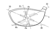
第1の主要リブ12は、垂直に対してトウ側に傾けることが好ましい。また、第2の主要リブ13は、垂直に対してヒール側に傾けることが好ましい。このように第1及び第2の主要リブ12、13を傾けることで、アマチュアゴルファの打点が集中するトウ上側−ヒール下側方向での反発性能を最大限に引き出すことができる。具体的には、図6に示すように、ゴルフクラブヘッド1を通常のアドレスポジションに置いたときの水平線30に対する第1及び第2の主要リブ12、13の中心線31の傾きθaを、約90°以下とすることが好ましく、約85°以下とすることがより好ましい。一方、このリブの傾きθaの下限を、約25°以上にすることが好ましく、約30°以上とすることがより好ましい。
The first
第3の主要リブ14は、水平に対してクラウン側またはホゼル側に傾けることが好ましい。また、第4の主要リブ15は、水平に対してソール側に傾けることが好ましい。このように第3及び第4の主要リブ14、15を傾けることで、トウの上方向での反発性能を最大減に引き出すことができる。具体的には、水平線30に対する第3及び第4の主要リブ14、15の中心線32の傾きθbを、約5°以上にすることが好ましく、約10°以上とすることがより好ましい。一方、リブの傾きθbの上限を、約80°以下とすることが好ましく、約70°以下とすることがより好ましい。補強リブ16は、その中心軸33が、第1及び第2の主要リブ12、13の中心軸31と、第3及び第4の主要リブ14、15の中心軸32とがなす角を二等分する(すなわち、両中心軸31、32に対してそれぞれθcの角度を有する)ことが好ましい。
The third
第1及び第2の主要リブ12、13は、中心軸31に沿って直線ではなく、S字状またはZ字状に滑らかに湾曲させることができる。また、第3及び第4の主要リブ14、15も中心軸32に沿って直線ではなく、S字状またはZ字状に滑らかに湾曲させることができる。このように主要リブを滑らかに湾曲させることで、トウ−クラウン区域19aとヒール−ソール区域19dの両方の区域の面積を広くすることができる。
The first and second
フェース部11の周辺部19の肉厚は、トウ−クラウン区域19a、トウ−ソール区域19b、ヒール−クラウン区域19c及びヒール−ソール区域19dの各区域内において、実質的に均一である。トウ−クラウン区域19a、トウ−ソール区域19b、ヒール−クラウン区域19c及びヒール−ソール区域19dの各肉厚は、同じにしても良いし、異なるようにしても良い。好ましくは、トウ−ソール区域19bとトウ−ソール区域19cの周辺部の反発係数を均等にするため、トウ−ソール区域19bの肉厚は、トウ−ソール区域19cの肉厚よりも薄くすることができる。この肉厚の差は、約0.025mm以上が好ましく、約0.05mm以上がより好ましく、約0.1mm以上が更に好ましい。一方、これら肉厚の差が大き過ぎると、均等の反発性能が得られない場合があるため、その上限は、約0.5mm以下が好ましく、約0.4mm以下がより好ましい。
The thickness of the peripheral portion 19 of the
また、トウ−クラウン区域19aの肉厚とトウ−ソール区域19bの肉厚は、同じであっても異なってもよいが、好ましくは、クラウン側とソール側の反発係数をより均等にするため、トウ−ソール区域19bの肉厚は、トウ−クラウン区域19aよりも薄くすることが好ましい。この肉厚の差は、約0.025mm以上が好ましく、約0.05mm以上がより好ましく、約0.1mm以上が更に好ましい。一方、これら肉厚の差が大き過ぎると、均等の反発性能が得られない場合があるため、その上限は、約0.5mm以下が好ましく、約0.4mm以下がより好ましい。
Further, the wall thickness of the toe-
ヒール−クラウン区域19cの肉厚とヒール−ソール区域19dの肉厚は、同じであっても異なってもよい。ヒール−クラウン区域19cとヒール−ソール区域19dとの肉厚を異なるようにする場合、肉厚の差は約0.05mm以上が好ましく、約0.5mm以下が好ましい。
The thickness of the heel-
交差部17は、図4及び図5に示すように、その中央部分において、最も肉厚が厚い中央部18を有している。また、交差部17は、中央部18から、周辺部19又は第1から第4の主要リブ12〜15に向かって、肉厚が減少するように形成されている。中央部18は、フェース部11のスイートスポット、すなわち、フェース面上に投影されるゴルフクラブヘッドの重心位置を含む。また、この中央部18は、第1及び第2の主要リブ12、13の中心軸と第3及び第4の主要リブ14、15の中心軸の交点を含む。この主要リブの交点とスイートスポットとは、同一であってもよいし、異なってもよい。また、この主要リブの交点は、フェース部11の表面に形成されるスコアライン(図示省略)上、又はフェース部のトウ側とヒール側に部分的に形成されるスコアライン(図示省略)の延長線上に存在しないように配置する。
As shown in FIGS. 4 and 5, the intersecting
中央部18の肉厚は、第1から第4の主要リブ12〜15のうちの最も肉厚が厚い主要リブにおける最も厚い部分よりも厚い。その肉厚の差は、約0.1mm以上が好ましく、約0.5mm以下が好ましい。また、中央部18は、図2に示すように、平面円形とすることが好ましい。平面円形の中央部18の半径は、約5mm以上が好ましく、約12mm以下が好ましい。なお、中央部18は、このような円形に限定されず、楕円形、長方形や菱形などの四角形、五角形や六角形などの多角形にしてもよい。
The thickness of the
第1から第4の主要リブ12〜15の最も厚い部分の各肉厚は、上述したように他の主要リブとの差を設けたり、周辺部19との差を設けたりするものの、おおむね、約3.0mm以上が好ましく、約3.2mm以上がより好ましい。一方、第1から第4の主要リブ12〜15の各肉厚の上限は、約4.2mm以下が好ましく、約4.0mm以下がより好ましい。また、補強リブ16の最も厚い部分の肉厚は、おおむね、約3.0mm以上が好ましく、約3.2mm以上がより好ましい。一方、補強リブ16の肉厚の上限は、約4.2mm以下が好ましく、約4.0mm以下がより好ましい。
Although the thickness of the thickest part of the first to fourth
周辺部19の肉厚は、上述したようにトウ−クラウン区域19a、トウ−ソール区域19b、ヒール−クラウン区域19c、ヒール−ソール区域19dにおいて肉厚の差が存在するものの、おおむね、約1.0mm以上が好ましく、約1.5mm以上がより好ましい。一方、周辺部19の肉厚の上限は、約3.0mm以下が好ましく、約2.5mm以下がより好ましい。また、中央部18の肉厚は、上述したように主要リブ12〜15との肉厚の差が存在するものの、おおむね、約2.5mm以上が好ましく、約2.7mm以上がより好ましい。一方、中央部18の肉厚の上限は、約4.0mm以下が好ましく、約3.8mm以下がより好ましい。
As described above, the thickness of the peripheral portion 19 is approximately about 1. although the thickness difference exists in the toe-
フェース部材10は、鍛造、鋳造いずれの方法でも形成可能である。また、フェース部材10の材料としては、チタンまたはチタン合金やステンレス鋼などを用いることができる。ゴルフクラブヘッド1の体積は、約100cc以上が好ましく、約150cc以上がより好ましい。一方、ゴルフクラブヘッド1の体積は、約500cc以下が好ましく、約460cc以下がより好ましい。また、ゴルフクラブヘッド1の重量は、約170g以上が好ましく、約175g以上がより好ましい。一方、ゴルフクラブヘッド1の重量は、約250g以下が好ましく、約245g以下がより好ましい。
The
なお、上述した実施の形態では、図1〜図6に示すように、補強リブ16を設けたが、図7に示すように、本発明は、補強リブを設けなくてもよい。また、上述した実施の形態では、フェース部材10が、フェース部11全体を備えていたが、フェース部11のスイートエリアを含むフェース部11の一部分であってもよい。その場合、フェース部材10の幅は、フェース部11の幅の約55%以上が好ましく、約60%以上がより好ましい。一方、フェース部材10の幅は、フェース部11の幅の約90%以下が好ましく、約85%以下がより好ましい。フェース部材10の高さは、フェース部11の高さの約50%以上が好ましく、約55%以上がより好ましい。また、フェース部材10の高さは、フェース部11の高さの約90%以下が好ましく、約85%以下がより好ましい。フェース部材10のトウ側およびヒール側の外縁は、第1及び第2の主要リブ12、13の中心軸31と実質的に平行であることが好ましい。本体部材20は、フェース部1のトウ側部分とヒール側部分を備えることが好ましい。
In the above-described embodiment, the reinforcing rib 16 is provided as shown in FIGS. 1 to 6. However, as shown in FIG. 7, the present invention does not need to provide the reinforcing rib. In the embodiment described above, the
本発明に係るゴルフクラブヘッドを作製し、そのフェース部の反発係数(COR:coefficient of restitution)について評価した。本実施例では、COR値を実際に測定する代わりに、特性時間(CT:Characteristic Time)を測定した。CT値は、全米ゴルフ協会(USGA)と英国ゴルフ協会(R&A)が採用したフェースのスプリング効果を簡易的で且つ精度高く測定することができる定量的な値であって、R&Aルールズ・リミテッドが承認したポータブル・ペンデュラム・マシン(携帯用振り子式測定器)で測定することができる。一般的に、フェースがよく撓む方がエネルギーの損失が少なく、ボールの初速が高いことから、CT値は、その撓みをボールとフェースの接触時間で表現したものである。現在、ルール上、その最上限を257(規定239+許容誤差18)μ秒と定めている。 A golf club head according to the present invention was produced and evaluated for its coefficient of restitution (COR). In this example, instead of actually measuring the COR value, characteristic time (CT) was measured. The CT value is a quantitative value that allows simple and accurate measurement of the face spring effect adopted by the US Golf Association (USGA) and the British Golf Association (R & A), and is approved by R & A Rules Limited. Can be measured with a portable pendulum machine (portable pendulum type measuring instrument). In general, the better the face is bent, the lower the energy loss and the higher the initial velocity of the ball. Therefore, the CT value represents the bending as the contact time between the ball and the face. Currently, the upper limit of the rule is 257 (specified 239 + allowable error 18) μsec.
実施例1のゴルフクラブヘッドは、図2に示すように、第1から第4の主要リブと補強リブを設け、このうち、ソール側に位置する主要リブの肉厚を、クラウン側に位置する主要リブの肉厚よりも、最も厚い部分において、0.3mm薄く形成した。実施例2のゴルフクラブヘッドは、周辺部の2つの区域の肉厚を変えた点を除き、実施例1と同様とした。実施例3は、図7に示すように、補強リブを設けなかった点を除き、実施例2と同様とした。一方、比較例のゴルフクラブヘッドは、図8に示すように、中央部58、主要リブ52〜55及び補強リブ56の肉厚を全て同じに形成した。また、周辺部59の肉厚も4つの区域で同じにした。これら実施例1〜3および比較例の中央部、4つの主要リブ、主要リブにより区分された4つの区域の周辺部、及び補強リブの各肉厚を、表1に示す。
As shown in FIG. 2, the golf club head of Example 1 is provided with first to fourth main ribs and reinforcing ribs, and among these, the thickness of the main rib located on the sole side is located on the crown side. In the thickest part, it was formed 0.3 mm thinner than the thickness of the main rib. The golf club head of Example 2 was the same as Example 1 except that the thickness of the two areas in the peripheral part was changed. Example 3 was the same as Example 2 except that no reinforcing rib was provided as shown in FIG. On the other hand, in the golf club head of the comparative example, as shown in FIG. 8, the

なお、共通するフェース部の条件としては、フェース部の幅を75mm、高さを43mmとし、第1から第4の主要リブは図2と同様に傾け、補強リブの長さは、トウ側に27mm、ヒール側に25mmとした。第1から第4の主要リブの幅は9.5mm、補強リブの幅は7.1mmとした。また、共通するゴルフクラブヘッドの条件としては、フェース部材の材料はチタン合金(Ti−6Al−4V)であり、ヘッド体積を460ccとし、ヘッド重量を190gとした。 The common face condition is that the face width is 75 mm and the height is 43 mm, the first to fourth main ribs are tilted in the same manner as in FIG. 2, and the length of the reinforcing rib is on the toe side. 27 mm and 25 mm on the heel side. The width of the first to fourth main ribs was 9.5 mm, and the width of the reinforcing ribs was 7.1 mm. As common golf club head conditions, the face member was made of titanium alloy (Ti-6Al-4V), the head volume was 460 cc, and the head weight was 190 g.
実施例および比較例について、ボールの打点におけるCT値を測定した。ボールの打点は、図9に示すように、垂直方向および水平方向に異なる15の打点について調べた。中央の打点40cは、スウィートスポットでの打球を想定しており、フェース部材の交差部内とした。それ以外の14の打点は、スウィートスポットを外した打球を想定した。中央の打点40cからトウ側およびヒール側にそれぞれ10mm離れた位置を、打点40b、40dとし、さらにトウ側およびヒール側にそれぞれ10mm離れた位置を、打点40a、40eとした。また、これら、5つの打点40a〜40eのクラウン側およびソール側にそれぞれ10mm離れた位置を、40aH〜40eHおよび40aL〜40eLとした。
About the Example and the comparative example, CT value in the hit point of a ball | bowl was measured. As shown in FIG. 9, the hitting points of the ball were examined for 15 different hitting points in the vertical direction and the horizontal direction. The center hit
以上の条件で、実施例1〜3及び比較例の各打点におけるCT値を測定した。その結果を表2〜表5に示す。なお、表2〜表5では、中央の打点40cの位置を0mmとし、クラウン側又はヒール側に向かう距離をプラスで、ソール側又はトウ側に向かう距離をマイナスで表した。
Under the above conditions, the CT values at the respective hit points of Examples 1 to 3 and the comparative example were measured. The results are shown in Tables 2-5. In Tables 2 to 5, the position of the center hit
表5に示すように、中央部、主要リブ及び補強リブの肉厚を全て同じに形成した比較例のゴルフクラブヘッドは、中央の打点40cからクラウン−ヒール方向に±10mm且つトウ−ヒール方向に±10mm離れた4つの打点40bH、40bL、40dH、40dLのCT値が、中央の打点40cのCT値に比べて10〜27μsec低かった。一方、クラウン側の第1及び第3の主要リブの肉厚を中央部の肉厚よりも0.2mm薄くし、ソール側の第2及び第4の主要リブの肉厚をクラウン側の第1及び第3の主要リブよりも0.3mm薄くした実施例1のゴルフクラブヘッドは、上記4つの打点40bH、40bL、40dH、40dLのCT値が、中央の打点40cのCT値に比べて5〜14μsec低いだけとなり、比較例の比べ、フェース部のCTをより均等にすることができた。
As shown in Table 5, the golf club head of the comparative example in which the thickness of the central part, the main rib and the reinforcing rib are all the same is ± 10 mm from the center hit
周辺部の肉厚をヒール−クラウン区域よりもトウ−ソール区域の方を0.5mm薄くした実施例2のゴルフクラブヘッドは、上記4つの打点40bH、40bL、40dH、40dLと中央の打点40cとのCT値の差が1〜10μsecとなり、フェース部のCTを更に均等にすることができた。また、補強リブを設けなかった実施例3のゴルフクラブヘッドも、上記4つの打点40bH、40bL、40dH、40dLと中央の打点40cとのCT値の差が1〜10μsecとなり、実施例2と同等にフェース部のCTを均等にすることができた。
In the golf club head of Example 2 in which the thickness of the peripheral portion is 0.5 mm thinner in the toe-sole area than in the heel-crown area, the four hit points 40bH, 40bL, 40dH, 40dL and the center hit
1 ゴルフクラブヘッド
10 フェース部材
11 フェース部
12 第1の主要リブ
13 第2の主要リブ
14 第3の主要リブ
15 第4の主要リブ
16 補強リブ
17 交差部
18 中央部
19 周辺部
20 本体部材
21 ソール部
22 クラウン部
23 トウ
24 ヒール
25 ホゼル部
30 水平線
31 第1及び第2の主要リブの中心軸
32 第3及び第4の主要リブの中心軸
33 補強リブの中心軸
40 打点
DESCRIPTION OF
Claims (5)
打球面を有するフェース部と、
このフェース部の内側面に配置された少なくとも4つの主要リブと
を含んでなり、前記4つの主要リブのうちの第1の主要リブは前記フェース部の中央部分からクラウン方向に延び、第2の主要リブは前記中央部分からソール方向に延び、その他の2つの主要リブも前記中央部分からフェース部の外側の方向に延び、
前記フェース部の肉厚が、前記中央部分、前記第1の主要リブ、前記第2の主要リブの順に薄くなるように形成されているゴルフクラブヘッド。 A golf club head having a hollow structure inside,
A face portion having a ball striking surface;
And at least four main ribs disposed on the inner side surface of the face portion, wherein the first main rib of the four main ribs extends in the crown direction from the central portion of the face portion, The main rib extends from the central portion toward the sole, and the other two main ribs also extend from the central portion toward the outside of the face portion.
A golf club head formed such that the thickness of the face portion becomes thinner in the order of the central portion, the first main rib, and the second main rib.
Priority Applications (2)
| Application Number | Priority Date | Filing Date | Title |
|---|---|---|---|
| JP2010029998A JP5421147B2 (en) | 2010-02-15 | 2010-02-15 | Golf club head |
| US13/026,781 US8465379B2 (en) | 2010-02-15 | 2011-02-14 | Golf club head |
Applications Claiming Priority (1)
| Application Number | Priority Date | Filing Date | Title |
|---|---|---|---|
| JP2010029998A JP5421147B2 (en) | 2010-02-15 | 2010-02-15 | Golf club head |
Publications (2)
| Publication Number | Publication Date |
|---|---|
| JP2011161135A true JP2011161135A (en) | 2011-08-25 |
| JP5421147B2 JP5421147B2 (en) | 2014-02-19 |
Family
ID=44370040
Family Applications (1)
| Application Number | Title | Priority Date | Filing Date |
|---|---|---|---|
| JP2010029998A Expired - Fee Related JP5421147B2 (en) | 2010-02-15 | 2010-02-15 | Golf club head |
Country Status (2)
| Country | Link |
|---|---|
| US (1) | US8465379B2 (en) |
| JP (1) | JP5421147B2 (en) |
Cited By (2)
| Publication number | Priority date | Publication date | Assignee | Title |
|---|---|---|---|---|
| JP2019130294A (en) * | 2017-12-28 | 2019-08-08 | テイラー メイド ゴルフ カンパニー インコーポレイテッド | Golf club head |
| US11117029B2 (en) * | 2012-05-31 | 2021-09-14 | Karsten Manufacturing Corporation | Golf club having a reinforced ball striking plate |
Families Citing this family (18)
| Publication number | Priority date | Publication date | Assignee | Title |
|---|---|---|---|---|
| US8439769B2 (en) * | 2005-09-07 | 2013-05-14 | Acushnet Company | Metal wood club with improved hitting face |
| US10888747B2 (en) | 2008-07-15 | 2021-01-12 | Taylor Made Golf Company, Inc. | Aerodynamic golf club head |
| US8858359B2 (en) | 2008-07-15 | 2014-10-14 | Taylor Made Golf Company, Inc. | High volume aerodynamic golf club head |
| US20100016095A1 (en) | 2008-07-15 | 2010-01-21 | Michael Scott Burnett | Golf club head having trip step feature |
| US8088021B2 (en) | 2008-07-15 | 2012-01-03 | Adams Golf Ip, Lp | High volume aerodynamic golf club head having a post apex attachment promoting region |
| JP2012061037A (en) * | 2010-09-14 | 2012-03-29 | Bridgestone Sports Co Ltd | Golf club head |
| JP5823122B2 (en) * | 2010-12-29 | 2015-11-25 | ダンロップスポーツ株式会社 | Golf club |
| JP2013000234A (en) * | 2011-06-14 | 2013-01-07 | Bridgestone Sports Co Ltd | Golf club head |
| US9119999B2 (en) * | 2013-02-08 | 2015-09-01 | Karsten Manufacturing Corporation | Golf club heads with frequency modulation devices and related methods |
| US12102892B2 (en) | 2014-05-15 | 2024-10-01 | Karsten Manufacturing Corporation | Club heads having reinforced club head faces and related methods |
| US12533558B2 (en) | 2014-05-15 | 2026-01-27 | Karsten Manufacturing Corporation | Club heads having reinforced club head faces and related methods |
| US12121782B2 (en) * | 2014-08-26 | 2024-10-22 | Parsons Xtreme Golf, LLC | Golf club heads and methods to manufacture golf club heads |
| US12179072B2 (en) * | 2014-08-26 | 2024-12-31 | Parsons Extreme Golf, Llc | Golf club heads and methods to manufacture golf club heads |
| US11697050B2 (en) * | 2014-08-26 | 2023-07-11 | Parsons Xtreme Golf, LLC | Golf club heads and methods to manufacture golf club heads |
| US20160067561A1 (en) * | 2014-09-05 | 2016-03-10 | Acushnet Company | Golf club head |
| US11618306B2 (en) | 2016-10-27 | 2023-04-04 | Nicholas J. Singer | Skeleton for truck bed and convertible top |
| US11986707B2 (en) * | 2020-08-21 | 2024-05-21 | Wilson Sporting Goods Co. | Faceplate of a golf club head |
| US11318358B1 (en) | 2020-12-29 | 2022-05-03 | Taylor Made Golf Company, Inc. | Golf club heads |
Citations (2)
| Publication number | Priority date | Publication date | Assignee | Title |
|---|---|---|---|---|
| JP2006230772A (en) * | 2005-02-25 | 2006-09-07 | Sri Sports Ltd | Golf club head |
| JP2008132276A (en) * | 2006-11-29 | 2008-06-12 | Sri Sports Ltd | Golf club head |
Family Cites Families (23)
| Publication number | Priority date | Publication date | Assignee | Title |
|---|---|---|---|---|
| US2087685A (en) * | 1935-02-16 | 1937-07-20 | William A Blair | Golf club |
| US3814437A (en) * | 1973-01-30 | 1974-06-04 | S Winquist | Symbolically reinforced golf club head |
| FR2689407A1 (en) * | 1992-04-01 | 1993-10-08 | Taylor Made Golf Co | Golf club head composed of a plastic hollow body and a sealing element. |
| JP2544362Y2 (en) * | 1992-07-28 | 1997-08-20 | 住友ゴム工業株式会社 | Iron type club head |
| JPH09239075A (en) | 1996-03-04 | 1997-09-16 | Mitsubishi Materials Corp | Golf club head |
| US5669829A (en) * | 1996-07-31 | 1997-09-23 | Pro Saturn Industrial Corporation | Golf club head |
| US5830084A (en) * | 1996-10-23 | 1998-11-03 | Callaway Golf Company | Contoured golf club face |
| EP1199088A4 (en) * | 2000-05-02 | 2002-10-02 | Mizuno Kk | Golf club |
| JP2002035178A (en) | 2000-07-26 | 2002-02-05 | Bridgestone Sports Co Ltd | Wood club |
| US6840872B2 (en) * | 2002-01-29 | 2005-01-11 | Yonex Kabushiki Kaisha | Golf club head |
| US6926618B2 (en) * | 2003-05-19 | 2005-08-09 | Karsten Manufacturing Corporation | Golf club with diagonally reinforced contoured front wall |
| JP4632342B2 (en) * | 2003-11-11 | 2011-02-16 | Sriスポーツ株式会社 | Golf club head |
| US8012041B2 (en) * | 2004-10-07 | 2011-09-06 | Callaway Golf Company | Golf club head with variable face thickness |
| US7101289B2 (en) * | 2004-10-07 | 2006-09-05 | Callaway Golf Company | Golf club head with variable face thickness |
| JP2006141806A (en) * | 2004-11-22 | 2006-06-08 | Sri Sports Ltd | Golf club head |
| US7387579B2 (en) * | 2006-06-28 | 2008-06-17 | O-Ta Precision Industry Co., Inc. | Golf club head |
| JP4241779B2 (en) | 2006-08-04 | 2009-03-18 | ヤマハ株式会社 | Golf club head |
| JP4500296B2 (en) * | 2006-10-19 | 2010-07-14 | Sriスポーツ株式会社 | Wood type golf club head |
| JP4365871B2 (en) * | 2007-04-05 | 2009-11-18 | Sriスポーツ株式会社 | Golf club head |
| JP4944830B2 (en) * | 2008-04-03 | 2012-06-06 | Sriスポーツ株式会社 | Golf club head |
| JP5349006B2 (en) * | 2008-10-29 | 2013-11-20 | ブリヂストンスポーツ株式会社 | Golf club head |
| US8070623B2 (en) * | 2008-11-21 | 2011-12-06 | Nike, Inc. | Golf club head or other ball striking device having stiffened face portion |
| JP2012061037A (en) * | 2010-09-14 | 2012-03-29 | Bridgestone Sports Co Ltd | Golf club head |
-
2010
- 2010-02-15 JP JP2010029998A patent/JP5421147B2/en not_active Expired - Fee Related
-
2011
- 2011-02-14 US US13/026,781 patent/US8465379B2/en not_active Expired - Fee Related
Patent Citations (2)
| Publication number | Priority date | Publication date | Assignee | Title |
|---|---|---|---|---|
| JP2006230772A (en) * | 2005-02-25 | 2006-09-07 | Sri Sports Ltd | Golf club head |
| JP2008132276A (en) * | 2006-11-29 | 2008-06-12 | Sri Sports Ltd | Golf club head |
Cited By (11)
| Publication number | Priority date | Publication date | Assignee | Title |
|---|---|---|---|---|
| US11117029B2 (en) * | 2012-05-31 | 2021-09-14 | Karsten Manufacturing Corporation | Golf club having a reinforced ball striking plate |
| US20220001250A1 (en) * | 2012-05-31 | 2022-01-06 | Karsten Manufacturing Corporation | Golf Club Having a Reinforced Ball Striking Plate |
| US11786788B2 (en) * | 2012-05-31 | 2023-10-17 | Karsten Manufacturing Corporation | Golf club having a reinforced ball striking plate |
| US20240042288A1 (en) * | 2012-05-31 | 2024-02-08 | Karsten Manufacturing Corporation | Golf Club Having a Reinforced Ball Striking Plate |
| JP2019130294A (en) * | 2017-12-28 | 2019-08-08 | テイラー メイド ゴルフ カンパニー インコーポレイテッド | Golf club head |
| JP2021137591A (en) * | 2017-12-28 | 2021-09-16 | テイラー メイド ゴルフ カンパニー インコーポレイテッド | Golf club head |
| US11253756B2 (en) | 2017-12-28 | 2022-02-22 | Taylor Made Golf Company, Inc. | Golf club head |
| JP7500493B2 (en) | 2017-12-28 | 2024-06-17 | テイラー メイド ゴルフ カンパニー インコーポレイテッド | Golf Club Head |
| JP2024096734A (en) * | 2017-12-28 | 2024-07-17 | テイラー メイド ゴルフ カンパニー インコーポレイテッド | Golf Club Head |
| US12048865B2 (en) | 2017-12-28 | 2024-07-30 | Taylor Made Golf Company, Inc. | Golf club head |
| JP7661568B2 (en) | 2017-12-28 | 2025-04-14 | テイラー メイド ゴルフ カンパニー インコーポレイテッド | Golf Club Head |
Also Published As
| Publication number | Publication date |
|---|---|
| JP5421147B2 (en) | 2014-02-19 |
| US20110201451A1 (en) | 2011-08-18 |
| US8465379B2 (en) | 2013-06-18 |
Similar Documents
| Publication | Publication Date | Title |
|---|---|---|
| JP5421147B2 (en) | Golf club head | |
| JP5451187B2 (en) | Golf club head | |
| JP2013000234A (en) | Golf club head | |
| JP2012061037A (en) | Golf club head | |
| JP4326559B2 (en) | Golf club head | |
| JP5174129B2 (en) | Golf club head | |
| JP5349006B2 (en) | Golf club head | |
| JP5989509B2 (en) | Golf club head and golf club | |
| JP6074220B2 (en) | Golf club head | |
| JP5947653B2 (en) | Golf club head | |
| JP5823122B2 (en) | Golf club | |
| JP4944830B2 (en) | Golf club head | |
| JP2013027587A (en) | Golf club head | |
| JP5583827B1 (en) | Golf club head | |
| JP2012005679A (en) | Golf club head | |
| JP2006141806A (en) | Golf club head | |
| JP2010029379A (en) | Wood-type golf club head | |
| JP2016019928A (en) | Golf club head | |
| JP2012120676A (en) | Golf club head | |
| KR20250048149A (en) | Iron-type golf club head with flex structure | |
| JP2020179030A (en) | Golf club head | |
| JP5374108B2 (en) | Golf club | |
| JP7206606B2 (en) | golf club set | |
| JP2011019708A (en) | Golf club head | |
| US10286264B2 (en) | Golf club set with progression of curvature of sole and center of gravity |
Legal Events
| Date | Code | Title | Description |
|---|---|---|---|
| A621 | Written request for application examination |
Free format text: JAPANESE INTERMEDIATE CODE: A621 Effective date: 20130118 |
|
| A977 | Report on retrieval |
Free format text: JAPANESE INTERMEDIATE CODE: A971007 Effective date: 20130927 |
|
| TRDD | Decision of grant or rejection written | ||
| A01 | Written decision to grant a patent or to grant a registration (utility model) |
Free format text: JAPANESE INTERMEDIATE CODE: A01 Effective date: 20131025 |
|
| A61 | First payment of annual fees (during grant procedure) |
Free format text: JAPANESE INTERMEDIATE CODE: A61 Effective date: 20131121 |
|
| R150 | Certificate of patent or registration of utility model |
Ref document number: 5421147 Country of ref document: JP Free format text: JAPANESE INTERMEDIATE CODE: R150 |
|
| R250 | Receipt of annual fees |
Free format text: JAPANESE INTERMEDIATE CODE: R250 |
|
| R250 | Receipt of annual fees |
Free format text: JAPANESE INTERMEDIATE CODE: R250 |
|
| R250 | Receipt of annual fees |
Free format text: JAPANESE INTERMEDIATE CODE: R250 |
|
| LAPS | Cancellation because of no payment of annual fees |