JP2011132838A - Single cylinder gas engine - Google Patents
Single cylinder gas engine Download PDFInfo
- Publication number
- JP2011132838A JP2011132838A JP2009291426A JP2009291426A JP2011132838A JP 2011132838 A JP2011132838 A JP 2011132838A JP 2009291426 A JP2009291426 A JP 2009291426A JP 2009291426 A JP2009291426 A JP 2009291426A JP 2011132838 A JP2011132838 A JP 2011132838A
- Authority
- JP
- Japan
- Prior art keywords
- control
- cycle
- engine
- gas engine
- cylinder gas
- Prior art date
- Legal status (The legal status is an assumption and is not a legal conclusion. Google has not performed a legal analysis and makes no representation as to the accuracy of the status listed.)
- Pending
Links
Images


Classifications
-
- Y—GENERAL TAGGING OF NEW TECHNOLOGICAL DEVELOPMENTS; GENERAL TAGGING OF CROSS-SECTIONAL TECHNOLOGIES SPANNING OVER SEVERAL SECTIONS OF THE IPC; TECHNICAL SUBJECTS COVERED BY FORMER USPC CROSS-REFERENCE ART COLLECTIONS [XRACs] AND DIGESTS
- Y02—TECHNOLOGIES OR APPLICATIONS FOR MITIGATION OR ADAPTATION AGAINST CLIMATE CHANGE
- Y02T—CLIMATE CHANGE MITIGATION TECHNOLOGIES RELATED TO TRANSPORTATION
- Y02T10/00—Road transport of goods or passengers
- Y02T10/10—Internal combustion engine [ICE] based vehicles
- Y02T10/30—Use of alternative fuels, e.g. biofuels
Landscapes
- Output Control And Ontrol Of Special Type Engine (AREA)
- Electrical Control Of Air Or Fuel Supplied To Internal-Combustion Engine (AREA)
Abstract
Description
本発明は、単気筒ガスエンジンに関し、より詳細には負荷変動への追従制御の高精度化に関する。 The present invention relates to a single-cylinder gas engine, and more particularly to improving the accuracy of tracking control for load fluctuations.
近年、省エネルギや二酸化炭素排出量削減を志向した分散型電源装置の開発が進められ、オフィスや集合住宅など電力消費地での導入が増加しつつある。分散型電源装置の一種に、燃料ガスを用いるガスエンジンを駆動源として電気エネルギおよび熱エネルギを生成するガスエンジン式コージェネレーション装置がある。この種の装置では、小出力用として単気筒ガスエンジンを用いることがある。そして、電気負荷の変動に追従するように、ガスエンジンに供給する燃料ガスおよび空気の量を制御して燃焼制御を行うことが一般的になっており、一例が特許文献1に開示されている。
In recent years, the development of distributed power supply devices aiming at energy saving and carbon dioxide emission reduction has been promoted, and the introduction in power consumption areas such as offices and apartment houses is increasing. One type of distributed power supply apparatus is a gas engine cogeneration apparatus that generates electric energy and heat energy using a gas engine using fuel gas as a drive source. In this type of apparatus, a single cylinder gas engine may be used for small output. And it is common to perform combustion control by controlling the amount of fuel gas and air supplied to the gas engine so as to follow the fluctuation of the electric load, and an example is disclosed in
特許文献1のガスエンジンの燃焼制御方法は、ガス燃料と空気とを混合した混合気を給気通路から燃焼室に導入して着火燃焼するように構成されたガスエンジンにおいて、所要のエンジン運転条件となるように混合気の流量を制御するとともに、給気通路における給気圧力をも制御するようにしている。これにより、給気通路における混合気の圧力損失を低減するとともに、発熱量の変動するガス燃料を用いる場合に空気過剰率を適正に保持する空燃比制御を可能として、安定したエンジン出力性能を発揮し得る、とされている。
The combustion control method for a gas engine disclosed in
ところで、特許文献1の実施例の説明によれば、混合気の流量および給気通路における給気圧力の制御は、コントローラが自動的に行う。コントローラには、通常コンピュータを内蔵してソフトウェアで動作する電子制御装置が用いられる。特許文献1に限らず、ガスエンジンの制御装置は、他の制御装置や各種センサから負荷変動やエンジン回転速度などの情報を取り込み、内部演算を実施し、燃料弁や混合気用スロットル弁などの制御用アクチュエータを制御するのが一般的である。通常、この制御のサイクルは、エンジンの動作サイクルが吸気、圧縮、燃焼、排気のいずれの工程であるかに関係なく、制御装置内部に設定された一定の制御周期を基にして独立に行われる。
By the way, according to the description of the embodiment of
このように、制御用アクチュエータの制御周期とエンジンの動作サイクルとが相互に独立していると、両者が整合せず良好な制御を行えないおそれがある。例えば、制御用アクチュエータを制御して混合気の条件を変更しても直ちに回転速度には反映されず、混合気が吸気され着火した時点以降に反映されるためタイムラグが生じる。また、回転速度が小さいときには動作サイクル中に複数回のアクチュエータ制御が行われるが、回転速度が増加すると動作サイクル中のアクチュエータ制御の回数が減少してタイムラグが顕著となるケースや、動作サイクル中にアクチュエータ制御が行われなくなるケースも生じ得る。 Thus, if the control cycle of the control actuator and the engine operation cycle are independent of each other, there is a possibility that the two do not match and good control cannot be performed. For example, even if the condition of the air-fuel mixture is changed by controlling the control actuator, it is not immediately reflected in the rotational speed, but is reflected after the time when the air-fuel mixture is inhaled and ignited, resulting in a time lag. In addition, when the rotation speed is low, actuator control is performed multiple times during the operation cycle, but when the rotation speed increases, the number of actuator controls during the operation cycle decreases and the time lag becomes significant, or during the operation cycle There may be cases where actuator control is not performed.
良好な制御を行えないと、負荷変動で目標回転速度が変化した場合に、回転速度の応答が遅れたり、目標回転速度をオーバーシュートして増減振動したりするおそれがある。特に、単気筒4サイクルガスエンジンでは、着火タイミングがクランク軸の2回転に1度しかないため、2気筒以上のエンジンと比較してタイムラグが大きくなり、比較的長時間に
わたり顕著に影響が出がちである。さらに、コージェネレーション装置に用いられるガスエンジンにあっては、電気負荷の変動に対応して空燃比を良好に保持することが難しくなり、負荷追従発電が不安定になるおそれがある。
If good control cannot be performed, when the target rotational speed changes due to load fluctuation, there is a possibility that the response of the rotational speed is delayed, or the target rotational speed is overshooted to increase or decrease. In particular, in a single-cylinder four-cycle gas engine, the ignition timing is only once every two rotations of the crankshaft, so the time lag is larger than in a two-cylinder or more engine, and the effect tends to be noticeable over a relatively long time. It is. Furthermore, in a gas engine used in a cogeneration system, it becomes difficult to maintain a good air-fuel ratio in response to fluctuations in electric load, and load following power generation may become unstable.
本発明は上記背景に鑑みてなされたものであり、負荷変動時の目標回転速度の変化に対し回転速度の応答遅れやオーバーシュートを抑制できる良好なアクチュエータ制御を行ってエンジンの能力を引き出すとともに、コージェネレーション装置用にあっては空燃比を常に良好に保持してエネルギ効率に優れた負荷追従発電を可能とする単気筒ガスエンジンを提供することを解決すべき課題とする。 The present invention has been made in view of the above-mentioned background, and performs an excellent actuator control capable of suppressing a response delay or an overshoot of the rotational speed with respect to a change in the target rotational speed at the time of a load change, and draws out the engine capacity, An object to be solved for a cogeneration system is to provide a single-cylinder gas engine that enables load-following power generation that is excellent in energy efficiency by maintaining a good air-fuel ratio at all times.
上記課題を解決する請求項1に係る単気筒ガスエンジンの発明は、エンジン本体と、前記エンジン本体に供給する燃料ガスおよび空気の量を調節する制御用アクチュエータと、負荷変動に応じて前記制御用アクチュエータを制御する制御装置とを備える単気筒ガスエンジンであって、前記制御装置は、前記制御用アクチュエータを制御する制御周期を前記エンジン本体の回転速度に対応して可変とし、前記エンジン本体の動作サイクルを検出するサイクル検出手段を備え、前記動作サイクルごとに1〜3回の頻度で前記制御用アクチュエータを制御することを特徴とする。
The invention of a single cylinder gas engine according to
請求項2に係る発明は、請求項1において、前記動作サイクルの工程を判別する工程判別手段を備え、前記制御装置は、前記工程判別手段による判別結果に基づいて前記制御用アクチュエータの制御タイミングを制御することを特徴とする。 According to a second aspect of the present invention, in the first aspect of the present invention, the apparatus includes a step determination unit that determines a step of the operation cycle, and the control device determines a control timing of the control actuator based on a determination result by the step determination unit. It is characterized by controlling.
請求項3に係る発明は、請求項2において、前記工程判別手段により前記動作サイクルの工程が判別できた場合、前記制御装置は、前記工程判別手段が判別した吸気工程よりも所定時間前に前記制御用アクチュエータを制御することを特徴とする。 According to a third aspect of the present invention, in the method according to the second aspect, in the case where the step of the operation cycle can be determined by the step determination unit, the control device is configured to perform the predetermined time before the intake step determined by the step determination unit A control actuator is controlled.
請求項4に係る発明は、請求項2または3において、前記工程判別手段は、クランク軸に固定され外周部分に複数の歯をもつ回転検出プーリーと、前記回転検出プーリーの前記複数の歯からパルス信号を生成するパルス発生器と、前記パルス信号からパルス整形波形を生成するパルス波形整形回路と、前記パルス整形波形から圧縮工程と排気工程の識別を行う識別部とを有することを特徴とする。 According to a fourth aspect of the present invention, in the second or third aspect, the process determining means includes a rotation detection pulley fixed to the crankshaft and having a plurality of teeth on an outer peripheral portion, and pulses from the plurality of teeth of the rotation detection pulley. A pulse generator that generates a signal, a pulse waveform shaping circuit that generates a pulse shaping waveform from the pulse signal, and an identification unit that identifies a compression process and an exhaust process from the pulse shaping waveform.
請求項5に係る発明は、請求項1において、前記制御装置は、前記動作サイクルごとに1.3〜2.5回の頻度で前記制御用アクチュエータを制御することを特徴とする。 According to a fifth aspect of the present invention, in the first aspect, the control device controls the control actuator at a frequency of 1.3 to 2.5 times for each operation cycle.
請求項6に係る発明は、請求項1〜5のいずれか一項において、単気筒ガスエンジンがコージェネレーション装置に用いられることを特徴とする。
The invention according to
請求項1に係る単気筒ガスエンジンの発明では、制御装置は制御周期を回転速度に対応して可変とし、エンジン本体の動作サイクルごとに1〜3回の頻度で前記制御用アクチュエータを制御する。このため、ガス燃料と空気とを混合した混合気の供給量や空燃比などの条件を毎回の動作サイクルで制御し、至近の着火タイミングに反映できる。すなわち、1動作サイクルの制御用アクチュエータ制御回数が1回以上あれば、エンジンの回転速度に影響を与えることのできる点火タイミングの前に確実にアクチュエータ制御を1回以上行うことができるため、前回の点火タイミングで影響を受けた現在のエンジン回転速度に対するアクチュエータ制御結果を次回の点火タイミングでエンジン回転速度に反映することが可能である。同制御回数が3回以下であれば、前回の点火タイミングで影響を受けた現在のエンジン回転速度に対して過剰にアクチュエータ制御を行うことが比較的抑制でき
るため、次回の点火タイミングでのエンジン回転速度が過剰に変動することを抑制できる。一方、同制御回数が1回より少ないと、前回の点火タイミングで影響を受けたエンジン回転速度に対してのアクチュエータ制御が1回もできない場合が存在するため、前回のアクチュエータ制御結果によるエンジン回転速度に対して応答が遅れてしまい回転速度の変動(ハンチング)が収束しなくなる場合がある。同制御回数が3回より多いと、1度の点火タイミングに対して何度もアクチュエータ制御を行ってしまうため、次回の点火タイミングでエンジン回転速度が過剰に影響を受けてしまいオーバーシュートが大きくなってしまう場合がある。したがって、制御のタイムラグを動作サイクルのサイクル周期未満に限定でき、負荷変動時の目標回転速度の変化に対し回転速度の応答遅れやオーバーシュートなどを抑制してエンジンの能力を引き出すことができる。
In the invention of the single-cylinder gas engine according to
請求項2に係る発明では、動作サイクルの工程を判別する工程判別手段を備え、工程判別手段による判別結果に基づいて制御用アクチュエータの制御タイミングを制御する。したがって、毎回の動作サイクルで制御用アクチュエータを確実に制御できる。 According to the second aspect of the present invention, the process discriminating means for discriminating the process of the operation cycle is provided, and the control timing of the control actuator is controlled based on the discrimination result by the process discriminating means. Therefore, the control actuator can be reliably controlled in each operation cycle.
請求項3に係る発明では、制御装置は、工程判別手段が判別した吸気工程よりも所定時間前に制御用アクチュエータを制御する。これにより、混合気の供給量や空燃比などの条件を制御した直後に混合気が吸気されて着火されるため、制御のタイムラグを抑制することができる。 In the invention according to claim 3, the control device controls the control actuator a predetermined time before the intake process determined by the process determining means. Thereby, immediately after controlling the conditions such as the supply amount of the air-fuel mixture and the air-fuel ratio, the air-fuel mixture is sucked and ignited, so that the control time lag can be suppressed.
請求項4に係る発明では、工程判別手段は、回転検出プーリー、パルス発生器、パルス波形整形回路、および識別部を有する。これにより、工程判別手段は、吸気、圧縮、燃焼、排気の各工程を確実に判別でき、制御装置は最適な制御タイミングを得て制御のタイムラグを抑制することができる。 In the invention according to claim 4, the process discrimination means includes a rotation detection pulley, a pulse generator, a pulse waveform shaping circuit, and an identification unit. Thereby, the process discriminating means can reliably discriminate each process of intake, compression, combustion, and exhaust, and the control device can obtain an optimal control timing and suppress a control time lag.
請求項5に係る発明では、動作サイクルごとに1.3〜2.5回の頻度で制御用アクチュエータを制御する。したがって、各工程を判別せずとも毎回の動作サイクルで制御用アクチュエータを制御でき、制御のタイムラグを動作サイクルのサイクル周期未満に限定でき、回転速度の応答遅れやオーバーシュートをより抑制することができる。 In the invention according to claim 5, the control actuator is controlled at a frequency of 1.3 to 2.5 times for each operation cycle. Therefore, the actuator for control can be controlled in each operation cycle without discriminating each process, the control time lag can be limited to less than the cycle period of the operation cycle, and the response delay and overshoot of the rotation speed can be further suppressed. .
請求項6に係る発明では、単気筒ガスエンジンがコージェネレーション装置に用いられる。したがって、回転速度の応答遅れやオーバーシュートなどを抑制して発電電力を安定させることができる。また、空燃比を常に良好に保持してエネルギー効率に優れた負荷追従発電が可能になる。
In the invention which concerns on
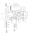
本発明を実施するための実施形態を、図1〜図8を参考にして説明する。図1は、本発明の実施形態の単気筒ガスエンジン1を用いたコージェネレーション装置の全体構成を説明する図である。図示される構成で、エンジン1のクランク軸23が発電機101に連結されて電気エネルギが生成され、エンジン1の冷却水が排熱回収装置102に循環されて熱エネルギが有効利用されるようになっている。単気筒ガスエンジン1は、エンジン本体2、燃料ガス供給部3、空気供給部4、混合気供給部5、排気部6、冷却水循環部7、工程判別器8、制御装置9などで構成されている。
An embodiment for carrying out the present invention will be described with reference to FIGS. FIG. 1 is a diagram illustrating the overall configuration of a cogeneration apparatus using a single
エンジン本体2は、単気筒のシリンダ21及びピストン22と、ピストン22の往復運動を回転運動に変換して出力するクランク軸23とを備えている。シリンダ21の上部には吸気ポート24及び排気ポート25と点火プラグ26が設けられ、シリンダ21を取り巻くようにウォータジャケット27が形成されている。
The
燃料ガス供給部3は、図略のガス供給源から燃料ガスをミキサー51に供給する燃料ガス通路に相当する部位である。燃料ガス供給部3には、ガス供給源側から順番に2個の電磁弁31、32、ガバナ33、および燃料弁34が設けられている。燃料弁34は、その開度AFを変化させて燃料ガスの供給量を調節する燃料予混合アクチュエータ35を有している。空気供給部4は、空気をミキサー51に供給する空気通路に相当する部位である。空気供給部4の途中にはエアクリーナ41が設けられている。混合気供給部5は、混合気をエンジン本体2の吸気ポート24に供給する部位である。混合気供給部5には、燃料ガスと空気とを混合して混合気を作成するミキサー51、および混合気の供給量を調節するスロットル弁52が設けられている。スロットル弁52は、その開度ASを変化させて混合気の供給量を調節するスロットルアクチュエータ53を有している。
The fuel gas supply unit 3 is a part corresponding to a fuel gas passage for supplying fuel gas from a gas supply source (not shown) to the
上述した燃料弁34の燃料予混合アクチュエータ35、およびスロットル弁52のスロットルアクチュエータ53は制御用アクチュエータであり、具体的にはステッピングモータを使用して制御装置9から制御する。
The
排気部6は、エンジン本体2の排気ポート25から外部へ排気ガスを放出する排気ガス通路に相当する部位である。排気部6には、排気ポート25側から順番に排気熱交換器61、および排気サイレンサー62が設けられている。冷却水循環部7は、冷却水を循環してエンジン本体2を冷却する冷却水通路に相当する部位である。冷却水は、エンジン本体2のウォータジャケット27から排気熱交換器61、排熱回収装置102を経てウォータジャケット27に循環するようになっている。これにより、冷却水は、エンジン本体2から熱エネルギを受け取るとともに、排気熱交換器61で排気ガスからも熱エネルギを受け取り、排熱回収装置102で熱エネルギを放出する。
The
工程判別器8は、工程判別手段の一部に相当する部位であり、クランク軸23に固定された回転検出プーリー81、およびパルス信号を生成するパルス発生器85を有している。図2は、工程判別器8を説明する図であり、(1)は図1の白抜き矢印A方向からみた構造図、(2)はパルス発生器85から制御装置9に出力されるパルス波形の図、(3)はパルス波形を整形したパルス整形波形の図である。図2(1)に示されるように、回転検出プーリー81は、クランク軸23に固定されて共に回転する鉄製の略円板状の部材であり、外周には3つの短歯82および1つの長歯83をもっている。各歯82、83は略矩形状で、その前縁82a、83aは90°ピッチの等間隔とされ、長歯83の円周方向の長さが短歯82より長く形成されている。
The
一方、パルス発生器85は、回転検出プーリー81の各歯82、83に臨むように、エ
ンジン本体2の外面に固設されている。パルス発生器85には、磁性体の接近および離隔による磁界変化を検出してパルス波形を出力する磁界検出センサを用いる。パルス発生器85は、クランク軸23と共に回転検出プーリー81が回転して各歯82、83の前縁82a、83aが近づくと、図2(2)に示されるように滑らかに変化する山状パルスの正電圧86を発生する。また、パルス発生器85は、各歯82、83の後縁82b、83bが近づくと、山状パルスの負電圧87を発生する。正電圧86の開始と負電圧87の終了の間で規定されるパルス時間に関しては、長歯83のパルス時間T83が短歯82のパルス時間T82より長くなり、両者を区別できる。なお、長歯83は、動作サイクル中の圧縮工程および排気工程で検出されるように配置されている。
On the other hand, the
制御装置9は、エンジン1の運転を制御する部位である。制御装置9は、燃料予混合アクチュエータ35およびスロットルアクチュエータ53を制御して、燃料弁34の開度AFおよびスロットル弁52の開度ASを調整し、かつ点火プラグ26の点火タイミングを制御する。さらに、制御装置9は、工程判別手段のうちのパルス波形整形回路および識別部の機能を兼ね、工程判別器8のパルス波形の処理を行う。
The
制御装置9の工程判別手段としての機能を詳述すると、まず図2(2)のパルス波形中の各パルス時間T82、T83を、単極矩形状のパルス整形波形T82A、T83Aに整形して、図2(3)のパルス整形波形を生成する。
To describe in detail the function of the
周知のように、4ストロークエンジンでは、1動作サイクルの間にクランク軸23が2回転する。このため、1動作サイクルの間に6個の短いパルス整形波形T82Aと2個の長いパルス整形波形T83Aが発生し、合計8個のパルス整形波形うちの連続する2個ずつのパルス整形波形の組み合わせがそれぞれ圧縮、燃焼、排気、吸気のいずれかの工程に割り当てられている。長いパルス整形波形T83Aは圧縮工程および排気工程に割り当てられている。具体的には、図2(3)に示すように、一方の長いパルス整形波形T83Aとその前の短いパルス整形波形T82Aが圧縮工程に割り当てられている。他方の長いパルス整形波形T83Aとその前の短いパルス整形波形T82Aが排気工程に割り当てられている。圧縮工程の後の2個の短いパルス整形波形T82Aが燃焼工程に割り当てられている。排気工程の後の2個の短いパルス整形波形T82Aが吸気工程に割り当てられている。
As is well known, in a four-stroke engine, the
圧縮工程ではシリンダ21内の混合気をピストン22で圧縮するため、クランク軸23の回転速度は遅くなる。一方、排気工程では排気ポート25が開いているため排気ガスの圧縮はなく、クランク軸23の回転速度は圧縮工程と比べて速くなる。そこで、制御装置9は、長いパルス整形波形T83Aの立ち上がりとその次の短いパルス整形波形T82Aの立ち上がりとの時間差を計測し、長い時間差TLを含む工程を圧縮工程と判別し、短い時間差TSを含む工程を排気工程と判別する。したがって、時間差TL、TSを比較することにより、圧縮工程と排気工程とを判別できる。
In the compression process, since the air-fuel mixture in the
なお、制御装置9は、上述の工程判別とともに、8個のパルス整形波形から1動作サイクルに要するサイクル周期Tを演算し、さらにその逆数を求め2倍して平均回転速度Nを演算している。したがって、本実施形態では、工程判別手段は動作サイクルを検出するサイクル検出手段としても機能する。
In addition to the above-described process determination, the
次に、制御装置9が燃料予混合アクチュエータ35およびスロットルアクチュエータ53を制御する動作について、図3を参考にして説明する。図3は、制御装置9が制御用アクチュエータを制御する動作を説明する動作フローの図である。図示されるように、制御装置9は、ステップS1で上述の工程判別処理を行い、ステップS2で動作サイクルのサイクル周期Tおよび平均回転速度Nを演算する。次に、ステップS3で、工程判別処理が
完了したか否か判断し、完了していればステップS4に進み、完了していなければステップS5に進む。工程判別処理が完了したか否かは、工程判別処理において、長いパルス整形波形T83Aの立ち上がりとその次の短いパルス整形波形T82Aの立ち上がりとの時間差を計測し、隣接する時間差の違いが計測されたか否かで判断する。すなわち、圧縮工程と排気工程が判別できたかどうかによって判断する。
Next, the operation in which the
ステップS4では、判別された工程中で吸気工程の開始よりも所定時間△T前に制御タイミングを設定する。所定時間△Tは、制御指令に対する燃料予混合アクチュエータ35およびスロットルアクチュエータ53の反応遅れ時間、および燃料弁34の開度AFおよびスロットル弁52の開度ASが変化してから、その変化によって燃料ガスの供給量や空燃比が変化した混合気がエンジン本体2のシリンダ21内に供給されるまでの供給遅れ時間を考慮して定めることができる。供給遅れ時間は、平均回転速度Nを考慮して定めることができる。所定時間△Tを適正に設定することで、制御直後に新しい条件の混合気が吸気されるようになり、制御のタイムラグを抑制できる。なお、所定時間△Tは演算によって求めることもできるが、実験的に求めても良い。実用上、所定時間△Tは前もって求め、制御装置9内に一覧表形式のマップとして保持しておく。一覧表形式のマップは、平均回転速度Nなどに対する所定時間△Tの関係が収められている。
In step S4, the control timing is set a predetermined time ΔT before the start of the intake process in the determined process. The predetermined time ΔT is a time when the
ステップS5では、工程が判別できていないので、所定時間△Tによる制御タイミングの設定は困難である。そこで、ステップS2で演算したサイクル周期Tごとに制御周期TCを設定する。具体的には、図4に示される制御周期TCを設定する。図4は、動作サイクル中の工程が判別できないときに、サイクル周期Tに基づいて制御周期TCを設定する方法を説明する図である。図中の横軸は平均回転速度Nであり、縦軸は周期または時間である。図中のグラフ(1)は動作サイクルのサイクル周期Tを示し、破線のグラフ(2)はサイクル周期Tの半分すなわちクランク軸23の回転周期TK(これは平均回転速度Nの逆数でもある)を示し、グラフ(3)は制御周期TCを示している。 In step S5, since the process cannot be determined, it is difficult to set the control timing based on the predetermined time ΔT. Therefore, a control cycle TC is set for each cycle cycle T calculated in step S2. Specifically, the control cycle TC shown in FIG. 4 is set. FIG. 4 is a diagram for explaining a method for setting the control period TC based on the cycle period T when the process in the operation cycle cannot be determined. The horizontal axis in the figure is the average rotational speed N, and the vertical axis is the period or time. Graph (1) in the figure shows the cycle period T of the operation cycle, and broken line graph (2) shows half of the cycle period T, that is, the rotation period TK of the crankshaft 23 (this is also the reciprocal of the average rotation speed N). The graph (3) shows the control cycle TC.
図中の下側回転速度Nminと上側回転速度Nmaxの間が単気筒ガスエンジン1の常用範囲である。さらに、常用範囲は、下側回転速度Nminから中間回転速度Nmidまでの低回転域と、中間回転速度Nmidから上側回転速度Nmaxまでの高回転域とに分けられている。Noは最低回転速度であり、エンジン始動時などに一時的に現れる。最低回転速度Noと下側回転速度Nminとの間に所定回転速度Naが設定されている。
The range between the lower rotational speed Nmin and the upper rotational speed Nmax in the figure is the normal range of the single
この実施形態では平均回転速度Nを3つの領域に分け、各領域に一定値の制御周期TCを設定している。すなわち、平均回転速度Nを、中間回転速度Nmid以上の第1領域、所定回転速度Naと中間回転速度Nmidとの間の第2領域、所定回転速度Naと最低回転速度Noとの間の第3領域に分けて一定値の制御周期TCを設定している。具体的には、各領域の最低の平均回転速度Nにおける制御周期TCを固定制御周期として設定している。すなわち、第1領域では中間回転速度Nmidにおける制御周期TCを第1固定制御周期TC1に設定し、第2領域では所定回転速度Naにおける制御周期TCを第2固定制御周期TC2に設定し、第3領域では最低回転速度Noにおける制御周期TCを第3固定制御周期TC3に設定する。 In this embodiment, the average rotational speed N is divided into three regions, and a constant control cycle TC is set in each region. That is, the average rotational speed N is set to a first region having an intermediate rotational speed Nmid or higher, a second region between the predetermined rotational speed Na and the intermediate rotational speed Nmid, and a third region between the predetermined rotational speed Na and the minimum rotational speed No. A constant control cycle TC is set for each region. Specifically, the control cycle TC at the lowest average rotation speed N in each region is set as a fixed control cycle. That is, in the first region, the control cycle TC at the intermediate rotational speed Nmid is set to the first fixed control cycle TC1, and in the second region, the control cycle TC at the predetermined rotational speed Na is set to the second fixed control cycle TC2, and the third In the region, the control cycle TC at the minimum rotational speed No is set to the third fixed control cycle TC3.
制御装置9は、複数個の固定された第1固定制御周期TC1、第2固定制御周期TC2、および第3固定制御周期TC3を保持し、動作サイクルごとに2回に近く制御用アクチュエータを制御できるように、高回転域を含む第1領域で制御周期TC=第1固定制御周期TC1を選択し、低回転域を含む第2領域で制御周期TC=第2固定制御周期TC2を選択し、第3領域で制御周期TC=第3固定制御周期TC3を選択する。図4に示された制御周期TCは、回転周期TKと同じか回転周期TKよりもわずかに大きくなっている。したがって、アクチュエータ制御は回転周期中に1回に近い頻度で行われ、換言すれば、
動作サイクルごとに2回以下かつ2回に近い頻度となる。
The
The frequency becomes less than twice and close to twice every operation cycle.
図3のステップS6に戻り、現在時刻が制御タイミングであるか判定する。判定は、スステップS4で設定した制御タイミング、あるいはステップS5で設定した制御周期TCに基づいた制御タイミングで行う。制御タイミングであれば、ステップS7で所定の内部演算に基づいて制御指令を定め、燃料予混合アクチュエータ35およびスロットルアクチュエータ53を制御し、燃料弁34の開度AFおよびスロットル弁52の開度ASを調整する。
Returning to step S6 of FIG. 3, it is determined whether the current time is the control timing. The determination is made at the control timing set in step S4 or the control timing based on the control cycle TC set in step S5. If it is the control timing, a control command is determined based on a predetermined internal calculation in step S7, the
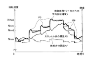
次に、上述の実施形態の単気筒ガスエンジン1の効果について、図5〜図8を参考にして説明する。図5は、実施形態の単気筒ガスエンジン1の効果を確認した検証実験結果の図であり、常用範囲で制御周期TCを第1固定制御周期TC1に設定している。図6も検証実験結果の図であり、常用範囲で制御周期TCを第2固定制御周期TC2に設定している。また、図7は制御周期TCを過小に設定した比較実験結果の図であり、図8は制御周期TCを過大に設定した比較実験結果の図である。
Next, the effect of the single
図5〜図8において、横軸は時間tであり、縦軸に平均回転速度N、燃料弁34の開度AF、スロットル弁52の開度ASを並記した。また、各実験では、目標回転速度をステップ状に変化させ、制御装置9は動作サイクルの工程を検出できないものとして制御周期TCによる追従制御を行わせて、上記3量N、AF、ASを測定した。具体的に、目標回転速度は下側回転速度Nminから中間回転速度Nmid、中高速回転速度Nmmを経て上側回転速度Nmaxまで増加させ、次いで、上側回転速度Nmaxから中高速回転速度Nmm、中間回転速度Nmidを経て下側回転速度Nminまで減少させた。
5 to 8, the horizontal axis represents time t, and the vertical axis represents the average rotational speed N, the opening degree AF of the
図5における制御周期TC=第1固定制御周期TC1であり、中間回転速度Nmidでちょうど動作サイクルごとに2回の頻度で制御を行う条件となっている。この場合、下側回転速度Nminで動作サイクルごとに2.31回(図4のM1点に相当)の頻度で制御を行う条件となっており、上側回転速度Nmax動作サイクルごとに1.71回(図4のM2点に相当)の頻度で制御を行う条件となっている。また、図6における制御周期TC=第2固定制御周期TC2であり、下側回転速度Nminで動作サイクルごとに1.85回(図4のM3点に相当)の頻度で制御を行う条件となっており、上側回転速度Nmax動作サイクルごとに1.37回(図4のM4点に相当)の頻度で制御を行う条件となっている。一方、図7における制御周期TC=TC1×0.25と過小に設定した。これは、常用範囲の領域で動作サイクルごとに6.84〜9.24回の頻度で制御を行う条件となっている。また、図8における制御周期TC=TC1×2.5と過大に設定した。これは、常用範囲の領域で動作サイクルごとに0.68〜0.92回の頻度で制御を行う条件となっている。 In FIG. 5, the control cycle TC = the first fixed control cycle TC1, and the condition is that the control is performed at the intermediate rotational speed Nmid at a frequency of just twice for each operation cycle. In this case, the condition is that the control is performed at a frequency of 2.31 times per operation cycle (corresponding to point M1 in FIG. 4) at the lower rotation speed Nmin, and 1.71 times per operation cycle of the upper rotation speed Nmax. This is a condition for performing control at a frequency (corresponding to point M2 in FIG. 4). Further, the control cycle TC in FIG. 6 is equal to the second fixed control cycle TC2, and the control is performed at a frequency of 1.85 times (corresponding to the point M3 in FIG. 4) for each operation cycle at the lower rotational speed Nmin. The condition is that the control is performed at a frequency of 1.37 times (corresponding to the point M4 in FIG. 4) for each upper rotation speed Nmax operation cycle. On the other hand, the control period TC = TC1 × 0.25 in FIG. This is a condition for performing control at a frequency of 6.84 to 9.24 times per operation cycle in the normal range. Further, the control cycle TC in FIG. 8 is set excessively as TC1 × 2.5. This is a condition in which control is performed at a frequency of 0.68 to 0.92 times for each operation cycle in the normal range.
図5に示される平均回転速度Nの応答性は、図7及び図8と比較すると良好である。ただし、図中P1に示されるように、下側回転速度Nminで若干の不安定が認められる。
図6に示される平均回転速度Nの応答性は、常用範囲の全領域で概ね良好である。
The responsiveness of the average rotation speed N shown in FIG. 5 is better than those in FIGS. However, as shown by P1 in the figure, some instability is observed at the lower rotational speed Nmin.
The responsiveness of the average rotational speed N shown in FIG. 6 is generally good in the entire range of the normal range.
一方、図7では、図中P2に示されるように目標回転速度が増加した直後に平均回転速度Nがオーバーシュートし、図中P3に示されるように目標回転速度が減少した直後に平均回転速度Nがアンダーシュートしている。また、図中P4に示されるように下側回転速度Nminにおいて平均回転速度Nのハンチングが収束しない。つまり、制御周期TCを過小に設定すると、制御用アクチュエータの反応遅れ時間と整合しないなどの理由により、平均回転速度Nの応答性が低下する。 On the other hand, in FIG. 7, the average rotational speed N overshoots immediately after the target rotational speed increases as indicated by P2 in the figure, and the average rotational speed immediately after the target rotational speed decreases as indicated by P3 in the figure. N undershoots. Further, as indicated by P4 in the figure, the hunting of the average rotational speed N does not converge at the lower rotational speed Nmin. That is, if the control cycle TC is set too small, the response of the average rotational speed N is lowered due to reasons such as inconsistency with the reaction delay time of the control actuator.
また、図8では、図中P5に示されるように目標回転速度が増加した直後、平均回転速
度Nが一旦オーバーシュートしたのち減少し落ち着くまでに時間がかかる。また、図中P6に示されるように目標回転速度が減少した直後、平均回転速度Nが落ち着くまでに時間がかかる。つまり、制御周期TCを過大に設定すると、平均回転速度Nの応答遅れが顕著となる。
In FIG. 8, as indicated by P <b> 5 in the figure, immediately after the target rotational speed increases, it takes time until the average rotational speed N decreases and settles after once overshooting. Further, as indicated by P6 in the figure, it takes time until the average rotational speed N settles immediately after the target rotational speed decreases. That is, when the control cycle TC is set excessively, the response delay of the average rotation speed N becomes significant.
図7および図8と比較すれば明らかなように、図5および図6における平均回転速度Nの応答性は良好であり、効果は明瞭である。図5および図6に示されるように、平均回転速度Nの常用範囲で制御周期TCを一定にしても良い。その際、平均回転速度Nの常用範囲で1動作サイクルごとの制御用アクチュエータの制御回数が1〜3回に入っていることが必要である。この制御回数は、好ましくは、1.3〜2.5回の方が良い。なお、1動作サイクルごとの制御回数の好ましい下限値としては1.4や1.5が選択できる。1動作サイクルごとの制御回数の好ましい上限値としては2.3や2.4が選択できる。また、図4に示されるように、平均回転速度を複数の領域に分けて(図4では3つの領域に分けているが、2つの領域でも、4つ以上の領域に分けても良い)各領域ごとに制御周期を設定しても良い。あるいは、平均回転速度に応じて制御周期を変化させても良い。例えば、制御周期TC=回転周期TKとする。いずれの場合にも、1動作サイクルごとの制御用アクチュエータの制御回数が1〜3回(好ましくは1.3〜2.5回)の条件を満たす必要がある。 As is clear from comparison with FIGS. 7 and 8, the responsiveness of the average rotational speed N in FIGS. 5 and 6 is good, and the effect is clear. As shown in FIG. 5 and FIG. 6, the control cycle TC may be constant within the normal range of the average rotation speed N. At that time, it is necessary that the number of times of control of the control actuator for each operation cycle is within the range of 1 to 3 in the normal range of the average rotation speed N. The number of times of control is preferably 1.3 to 2.5. Note that 1.4 or 1.5 can be selected as a preferable lower limit value of the number of times of control per operation cycle. As a preferable upper limit value of the number of times of control per one operation cycle, 2.3 or 2.4 can be selected. Also, as shown in FIG. 4, the average rotational speed is divided into a plurality of regions (in FIG. 4, it is divided into three regions, but it may be divided into two regions or four or more regions). A control cycle may be set for each region. Alternatively, the control cycle may be changed according to the average rotation speed. For example, control cycle TC = rotation cycle TK. In any case, it is necessary to satisfy the condition that the number of times of control of the control actuator per operation cycle is 1 to 3 times (preferably 1.3 to 2.5 times).
実施形態の単気筒ガスエンジン1では、制御装置9は制御周期TCを平均回転速度Nに対応して可変とし、動作サイクルごとに2回に近い頻度で、燃料予混合アクチュエータ35およびスロットルアクチュエータ53を制御して、燃料弁34の開度AFおよびスロットル弁52の開度ASを調整する。これにより、制御のタイムラグを短縮できる。したがって、負荷変動に対し平均回転速度Nの応答遅れやオーバーシュートなどを抑制してエンジン1の能力を引き出すことができる。
In the single-
さらに、実施形態の単気筒ガスエンジン1はコージェネレーション装置に用いた場合、発電電力を安定させることができる。また、空燃比を常に良好に保持してエネルギ効率に優れた負荷追従発電が可能になる。
Furthermore, when the single-
なお、上記実施形態では、図2に示される工程判別器8を備える工程判別手段を、動作サイクルを検出するサイクル検出手段として使用したが、これに限定されない。例えば、単純にクランク軸の1回転を検出するセンサを備え、回転速度および動作サイクルのサイクル周期を求めるようにしてもよい。あるいは、着火タイミングを検出して、回転速度および動作サイクルのサイクル周期を求めるようにしてもよい。また、制御周期TCの設定も図4の実施形態に限定されず、様々な設定方法を用いることができる。さらに、図5および図6の結果から明らかなように、制御周期TCを設定して制御タイミングを制御する方法は、吸気工程よりも所定時間前に制御タイミングを設定する制御がなくても回転速度の応答遅れやオーバーシュートを良好に抑制できる。したがって、図3におけるステップS3やステップS4が存在しない制御も可能である。
In the above embodiment, the process discriminating means including the
1:単気筒ガスエンジン
2:エンジン本体
21:シリンダ 22:ピストン 23:クランク軸 24:吸気ポート
25:排気ポート 26:点火プラグ 27:ウォータジャケット
3:燃料ガス供給部
34:燃料弁 35:燃料予混合アクチュエータ
4:空気供給部
5:混合気供給部
51:ミキサー 52:スロットル弁 53:スロットルアクチュエータ
6:排気部
7:冷却水循環部
8:工程判別器
81:回転検出プーリー 82:短歯 83:長歯 85:パルス発生器
9:制御装置
101:発電機 102:排熱回収装置
T:サイクル周期 TK:回転周期 TC:制御周期
TC1、TC2、TC3:第1、第2、および第3固定制御周期
N:平均回転速度
Nmin:下側回転速度 Nmid:中間回転速度 Nmax:上側回転速度
1: Single cylinder gas engine 2: Engine body 21: Cylinder 22: Piston 23: Crankshaft 24: Intake port 25: Exhaust port 26: Spark plug 27: Water jacket 3: Fuel gas supply unit 34: Fuel valve 35: Fuel reserve Mixing actuator 4: Air supply unit 5: Mixture supply unit 51: Mixer 52: Throttle valve 53: Throttle actuator 6: Exhaust unit 7: Cooling water circulation unit 8: Process discriminator 81: Rotation detection pulley 82: Short teeth 83: Long Teeth 85: Pulse generator 9: Control device 101: Generator 102: Waste heat recovery device T: Cycle period TK: Rotation period TC: Control period TC1, TC2, TC3: First, second, and third fixed control periods N: Average rotational speed Nmin: Lower rotational speed Nmid: Intermediate rotational speed Nmax: Upper rotational speed
Claims (6)
前記制御装置は、前記制御用アクチュエータを制御する制御周期を前記エンジン本体の回転速度に対応して可変とし、前記エンジン本体の動作サイクルを検出するサイクル検出手段を備え、前記動作サイクルごとに1〜3回の頻度で前記制御用アクチュエータを制御することを特徴とする単気筒ガスエンジン。 A single-cylinder gas engine comprising an engine body, a control actuator that adjusts the amount of fuel gas and air supplied to the engine body, and a control device that controls the control actuator according to load fluctuations,
The control device includes a cycle detection means for making a control cycle for controlling the control actuator variable according to a rotation speed of the engine body, and detecting an operation cycle of the engine body. A single-cylinder gas engine that controls the control actuator three times.
Priority Applications (1)
| Application Number | Priority Date | Filing Date | Title |
|---|---|---|---|
| JP2009291426A JP2011132838A (en) | 2009-12-22 | 2009-12-22 | Single cylinder gas engine |
Applications Claiming Priority (1)
| Application Number | Priority Date | Filing Date | Title |
|---|---|---|---|
| JP2009291426A JP2011132838A (en) | 2009-12-22 | 2009-12-22 | Single cylinder gas engine |
Publications (1)
| Publication Number | Publication Date |
|---|---|
| JP2011132838A true JP2011132838A (en) | 2011-07-07 |
Family
ID=44345854
Family Applications (1)
| Application Number | Title | Priority Date | Filing Date |
|---|---|---|---|
| JP2009291426A Pending JP2011132838A (en) | 2009-12-22 | 2009-12-22 | Single cylinder gas engine |
Country Status (1)
| Country | Link |
|---|---|
| JP (1) | JP2011132838A (en) |
Cited By (1)
| Publication number | Priority date | Publication date | Assignee | Title |
|---|---|---|---|---|
| JP2013516571A (en) * | 2010-01-08 | 2013-05-13 | ローベルト ボツシユ ゲゼルシヤフト ミツト ベシユレンクテル ハフツング | Method for controlling HCCI combustion in a reactor of an internal combustion engine |
-
2009
- 2009-12-22 JP JP2009291426A patent/JP2011132838A/en active Pending
Cited By (2)
| Publication number | Priority date | Publication date | Assignee | Title |
|---|---|---|---|---|
| JP2013516571A (en) * | 2010-01-08 | 2013-05-13 | ローベルト ボツシユ ゲゼルシヤフト ミツト ベシユレンクテル ハフツング | Method for controlling HCCI combustion in a reactor of an internal combustion engine |
| US9359969B2 (en) | 2010-01-08 | 2016-06-07 | Robert Bosch Gmbh | Method for regulating HCCI combustion in a reactor of an internal combustion engine |
Similar Documents
| Publication | Publication Date | Title |
|---|---|---|
| CN101868617B (en) | Internal combustion engine control device | |
| JP4462018B2 (en) | Engine control system | |
| CN101365876A (en) | virtual fuel quality sensor | |
| CN103732887A (en) | Control apparatus for internal combustion engine and method therefor | |
| JP5625815B2 (en) | Engine cooling control device | |
| CN104603432A (en) | Minimization of combustion noise of internal combustion engine based on detection of instability of position of maximum of cylinder pressure gradient | |
| CN101865067A (en) | Ignition control device for general purpose internal combustion engine | |
| US4721082A (en) | Method of controlling an air/fuel ratio of a vehicle mounted internal combustion engine | |
| JP5281668B2 (en) | General-purpose engine electronic governor device and hunting control method | |
| CN104832310A (en) | Method and system of controlling bank to bank component temperature protection during individual cylinder knock control | |
| JPS6193269A (en) | Method of optimally setting setting parameter of periodically operating machine | |
| JP2000352347A (en) | Engine control device | |
| JP2007327406A (en) | Control device and method for internal combustion engine | |
| CN104100398A (en) | Mitigate Stochastic Pre-ignition (SPI) Using Adaptive SPI Scaler | |
| CN108798924B (en) | Controller for Internal Combustion Engine | |
| JP2011132838A (en) | Single cylinder gas engine | |
| SE521858C2 (en) | Method for reducing cold start emissions from internal combustion engines | |
| JP2005083317A (en) | Control device for internal combustion engine | |
| JP5444804B2 (en) | Power generation control device | |
| JP2884347B2 (en) | Ignition coil energization control device for internal combustion engine | |
| JP2008050967A (en) | Method for avoiding knocking in spark ignition type engine | |
| JP5022333B2 (en) | No-load detection method and apparatus for general-purpose internal combustion engine | |
| JP4444280B2 (en) | Control method of piston engine operated by ignition by compression of homogeneous mixture and piston engine | |
| US8903634B2 (en) | Engine control apparatus | |
| JP6489607B2 (en) | Control device for internal combustion engine |