JP2011129372A - Secondary battery device - Google Patents
Secondary battery device Download PDFInfo
- Publication number
- JP2011129372A JP2011129372A JP2009286676A JP2009286676A JP2011129372A JP 2011129372 A JP2011129372 A JP 2011129372A JP 2009286676 A JP2009286676 A JP 2009286676A JP 2009286676 A JP2009286676 A JP 2009286676A JP 2011129372 A JP2011129372 A JP 2011129372A
- Authority
- JP
- Japan
- Prior art keywords
- battery
- secondary battery
- opening
- explosion
- liquid reservoir
- Prior art date
- Legal status (The legal status is an assumption and is not a legal conclusion. Google has not performed a legal analysis and makes no representation as to the accuracy of the status listed.)
- Pending
Links
Images





Classifications
-
- Y—GENERAL TAGGING OF NEW TECHNOLOGICAL DEVELOPMENTS; GENERAL TAGGING OF CROSS-SECTIONAL TECHNOLOGIES SPANNING OVER SEVERAL SECTIONS OF THE IPC; TECHNICAL SUBJECTS COVERED BY FORMER USPC CROSS-REFERENCE ART COLLECTIONS [XRACs] AND DIGESTS
- Y02—TECHNOLOGIES OR APPLICATIONS FOR MITIGATION OR ADAPTATION AGAINST CLIMATE CHANGE
- Y02E—REDUCTION OF GREENHOUSE GAS [GHG] EMISSIONS, RELATED TO ENERGY GENERATION, TRANSMISSION OR DISTRIBUTION
- Y02E60/00—Enabling technologies; Technologies with a potential or indirect contribution to GHG emissions mitigation
- Y02E60/10—Energy storage using batteries
Landscapes
- Battery Mounting, Suspending (AREA)
- Gas Exhaust Devices For Batteries (AREA)
Abstract
【課題】電池セルから噴出したガスの排出経路を確保することが可能な二次電池装置を提供する。
【解決手段】防爆弁が設けられた面を各々有する複数の電池セルと、複数の前記電池セルの各々の防爆弁と対向する開口が形成されるとともに排出口まで延出した管路と、前記管路の前記開口から前記排出口までの中途に設けられた液溜部と、を備えたことを特徴とする二次電池装置。
【選択図】 図2A secondary battery device capable of securing a discharge path for gas ejected from a battery cell is provided.
A plurality of battery cells each having a surface provided with an explosion-proof valve, a pipe line formed with an opening facing each explosion-proof valve of the plurality of battery cells and extending to a discharge port, A secondary battery device comprising: a liquid reservoir provided midway from the opening of the conduit to the discharge port.
[Selection] Figure 2
Description
本発明は、二次電池装置に関する。 The present invention relates to a secondary battery device.
近年、二次電池装置は、コードレス携帯型電子機器の電源、さらには自動車などの車両駆動用の電源などとして注目されている。 In recent years, secondary battery devices have attracted attention as power sources for cordless portable electronic devices, and further as power sources for driving vehicles such as automobiles.
例えば、特許文献1においては、電池の異常時に電池内部から高温高圧のガスが噴出する可能性があるため、電池から放出されたガスを外部に排出する経路を有し、その経路でガスの温度を低下させて外部に排出する構成の電池パックが開示されている。特に、この特許文献1には、ガスを排出する経路が熱による損傷を受けないように、放熱性や耐熱性を考慮した材料からなるダクトを設けることが開示されている。
For example, in
ガス排出経路に沿って高温のガスが排出された際、このガスが冷えて液化した電解液によりガス排出経路が詰まり、電池外へのガスの排出が阻害されるおそれがある。 When high-temperature gas is discharged along the gas discharge path, the gas discharge path is clogged by the electrolyte that is cooled and liquefied, and gas discharge to the outside of the battery may be hindered.
特に、電気自動車などのアプリケーションでは、多数の電池セルを配列して、これらを電気的に並列に接続して用いられる。このような構成では、1個の電池セルから高温のガスが噴出した後に、他の電池セルも熱暴走などにより連鎖的にガスを噴出するおそれがある。このため、電池セルから噴出したガスの排出経路を確保することが求められる。 In particular, in applications such as an electric vehicle, a large number of battery cells are arranged and electrically connected in parallel. In such a configuration, after a high-temperature gas is ejected from one battery cell, there is a possibility that other battery cells also eject gas in a chain due to thermal runaway or the like. For this reason, it is required to secure a discharge path for the gas ejected from the battery cell.
本発明の目的は、電池セルから噴出したガスの排出経路を確保することが可能な二次電池装置の提供を可能とすることにある。 An object of the present invention is to make it possible to provide a secondary battery device capable of securing a discharge path for gas ejected from a battery cell.
本発明の一態様によれば、
防爆弁が設けられた面を各々有する複数の電池セルと、複数の前記電池セルの各々の防爆弁と対向する開口が形成されるとともに排出口まで延出した管路と、前記管路の前記開口から前記排出口までの中途に設けられた液溜部と、を備えたことを特徴とする二次電池装置が提供される。
According to one aspect of the invention,
A plurality of battery cells each having a surface provided with an explosion-proof valve; a pipe line formed with an opening facing each explosion-proof valve of the plurality of battery cells and extending to a discharge port; and the pipe line There is provided a secondary battery device comprising a liquid reservoir provided in the middle from the opening to the discharge port.
本発明の他の態様によれば、
防爆弁が設けられた面を各々有する複数の電池セルと、複数の前記電池セルの各々の面の前記電池セルの各々の前記防爆弁に対向する開口が形成された電池支持部を有する支持枠と、前記電池支持部に位置し前記開口に連通する管路と、前記電池支持部の外に位置し前記管路に連通する液溜部と、を備えたことを特徴とする二次電池装置が提供される。
According to another aspect of the invention,
A support frame having a plurality of battery cells each having a surface provided with an explosion-proof valve, and a battery support portion formed with openings facing each of the battery cells on each surface of the plurality of battery cells. A secondary battery device comprising: a conduit that is located on the battery support and communicates with the opening; and a liquid reservoir that is located outside the battery support and communicates with the conduit. Is provided.
本発明は、電池セルから噴出したガスの排出経路を確保することが可能な二次電池装置の提供が可能となる。 According to the present invention, it is possible to provide a secondary battery device capable of securing a discharge path for gas ejected from a battery cell.
以下、本発明の一態様について、図面を参照しながら詳細に説明する。なお、各図において、同一又は類似した機能を発揮する構成要素には同一の参照符号を付し、重複する説明は省略する。 Hereinafter, one embodiment of the present invention will be described in detail with reference to the drawings. In each figure, the same reference numerals are given to components that exhibit the same or similar functions, and duplicate descriptions are omitted.
まず、本実施形態における二次電池装置に適用可能な電池セルについて説明する。 First, the battery cell applicable to the secondary battery device in this embodiment will be described.
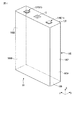
図1は、本実施形態における二次電池装置に適用可能な電池セル10の外観を概略的に示す斜視図である。
FIG. 1 is a perspective view schematically showing an external appearance of a
電池セル10の外面は、例えばアルミニウムなどの金属容器によって構成されている。このような電池セル10の外形は、第1方向Xの長さが第1方向Xに直交する第2方向Yの長さ及び第1方向X及び第2方向Yに直交する第3方向Zの長さよりも短い略直方体である。この電池セル10は、セル端子11が設けられた上面10T、この上面10Tに対向する底面10B、及び、上面10Tと底面10Bとを繋ぐ側面10Sを有している。上面10T及び底面10Bは、XY平面に平行であり、第2方向Yを長手方向とする略長方形状である。側面10Sは、XZ平面と平行な一対の側面10S1及び10S2、及び、YZ平面と平行な一対の側面10S3及び10S4からなる。
The outer surface of the
上面10Tに設けられたセル端子11は、正極端子11P及び負極端子11Nからなる。これらの正極端子11P及び負極端子11Nは、例えばアルミニウムなどの導電材料によって形成されている。また、正極端子11P及び負極端子11Nは、第2方向Yに並んでいる。図1に示した例では、正極端子11P及び負極端子11Nは、略四角形状であり、上面10Tから突出している。
The
また、この上面10Tには、局所的に肉薄に形成された防爆弁12が設けられている。この防爆弁12は、例えば略四角形状であり、正極端子11Pと負極端子11Nとの間に位置している。電池セル10の内部には、電解液が充填されており、電池セル10の内部圧力が過度に高まると、防爆弁12が開弁し、防爆弁12から高温のガス(電解液の気化成分)が噴出される。噴出したガスには、気化せずに液状のままの電解液が含まれることもある。
The
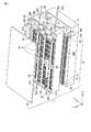
図2は、本実施形態における二次電池装置1を上方から見た分解斜視図である。なお、この図2においては、二次電池装置1を構成する部材の一部を省略している。
FIG. 2 is an exploded perspective view of the
二次電池装置1は、その外形が略直方体であり、複数の電池セル10、第1支持枠20、第2支持枠30、トップカバー40などを備えている。図示した例の二次電池装置1は、合計90個の電池セル10を備えている。つまり、二次電池装置1の長手方向である第1方向Xに沿った1列につき30個の電池セル10が並んでいる。また、このような電池セル10は、第2方向Yに沿って3列に並んでいる。第1方向Xに沿って並んだ30個の電池セル10は、各々のセル端子11及び防爆弁12が第1方向Xに平行な一直線上に並び且つXY平面と平行な同一平面上に位置するように配列されている。第2方向Yに並んだ3個の電池セル10についても、各々のセル端子11及び防爆弁12がXY平面と平行な同一平面上に位置するように配列されている。
The
第1支持枠20は、XY平面において、第1方向Xに沿った長さが第2方向Yに沿った長さよりも長い長方形状に形成されている。このような第1支持枠20は、上面10Tを上方に向けた電池セル10の各々の底面10B及び側面10Sを支持する。すなわち、第1支持枠20は、電池セル10の各々を支持する第1電池支持部21を有している。このような第1電池支持部21には、各電池セル10が嵌め込まれている。各電池セル10の上面10Tは、第1電池支持部21から突出している。また、図示した例では、第1支持枠20は、第1電池支持部21に隣接して各種制御回路を収容するための回路収容部22を有している。なお、この回路収容部22については詳述しない。
The
第2支持枠30は、第1支持枠20と同様にXY平面において、第1方向Xに沿った長さが第2方向Yに沿った長さよりも長い長方形状に形成されている。この第2支持枠30は、第1支持枠20の第3方向Zに沿った上方に位置し、複数の電池セル10の各々の上面10Tを支持する。すなわち、第2支持枠30は、電池セル10の各々を支持する第2電池支持部31を有している。このような第2電池支持部31には、第1電池支持部21から突出した各電池セル10の上面10Tが嵌め込まれる。この第2電池支持部31には、嵌め込まれた電池セル10の各々の2つのセル端子11をそれぞれ露出する開口311及び312が形成されている。これらの開口311及び312は、第2方向Yに並んでいる。
Similarly to the
また、この第2電池支持部31には、第1方向Xに沿って延出した凹所31Aが形成されている。この凹所31Aは、第1方向Xに沿って延出した一対のリブ31B及び31Cの間に形成されている。凹所31Aには、嵌め込まれた電池セル10の各々の防爆弁12と対向する開口313が形成されている。このような凹所31Aは、リブ31B及び31Cに跨って配置されたカバー32によって塞がれている。このような凹所31A及びカバー32は、開口313と連通する第1管路D1を構成する。この第1管路D1は、第1方向Xに沿って延出している。図示した例では、第2電池支持部31には、3つの第1管路D1が互いに平行に形成されている。
The second
また、図示した例では、第2支持枠30は、第2電池支持部31に隣接して設けられた液溜部33を有している。第2電池支持部31及び液溜部33は、第1方向Xに並んでいる。この液溜部33は、XY平面と平行な底部33Bを有している。
In the illustrated example, the
第2支持枠30において、これらの第2電池支持部31及び液溜部33は、第1方向Xに沿って延出した一対の側壁35A及び35Bと、第2方向Yに沿って延出した一対の側壁35Cおよび35Dとによって囲まれている。第2電池支持部31と液溜部33との間は、側壁35Aと側壁35Bとを繋ぎ第2方向Yに沿って延出した仕切板36によって仕切られている。仕切板36には、第1管路D1に連通した開口361が形成されている。また、液溜部33を挟んで仕切板36に向かい合う第2支持枠30の側壁35Dには、開口351が形成されている。仕切板36の開口361と、側壁35Dの開口351とは、液溜部33を挟んで対向しており、例えば、両者は第1方向Xに沿って同軸上に位置している。
In the
このような第2支持枠30に対し、例えばパイプPが接続されている。このパイプPは、例えば、仕切板36の開口361に嵌め込まれ液溜部33を経由して側壁35Dの開口351を貫通し、第1管路D1に繋がった第2管路D2を構成している。このようなパイプPは、第1方向Xに沿って延出し、二次電池装置1の外部に引き出されている。図示した例では、3本のパイプPが互いに平行に配置されている。これらのパイプPは、二次電池装置1の外部に設けられた排出口Doutに接続されている。つまり、パイプPによって構成される第2管路D2は、第1管路D1と排出口Doutとを繋いでいる。液溜部33は、第2管路D2の中途、つまり第1管路D1と接続位置と排出口Doutとの間に設けられている。排出口Doutの設置位置は、二次電池装置1の外部であれば特に制限はないが、例えば、排出口Doutは二次電池装置1を搭載した車体の外に向けて設置される。
For example, a pipe P is connected to the
なお、第2管路D2の構造については、特にこの例に限らず、例えば、3つの開口361に各々嵌め込まれた3本のパイプPを液溜部33の上方で1本にパイプに接続し、側壁35Dに形成された1つの開口351を貫通して二次電池装置1の外部に引き出されても良い。
The structure of the second conduit D2 is not particularly limited to this example. For example, three pipes P respectively fitted in the three
上述した第1管路D1及び第2管路D2は、各電池セル10の防爆弁12に対向する開口313と二次電池装置1の外部に設けられた排出口Doutとの間に排出経路を形成する。これらの第1管路D1、第2管路D2、及び、排出口Doutは排出管Dを構成する。第1管路D1及び第2管路D2は、上述した例のように互いに異なる部材を連結する構成に限らず、一連の部材によって構成しても良い。また、外部への排出経路として、側壁35A乃至35Dのいずれかに設けられた開口351から二次電池装置1の重力方向下側に引き出す構成であっても良い。
The first conduit D1 and the second conduit D2 described above provide a discharge path between the opening 313 facing the explosion-
トップカバー40は、第2支持枠30の第3方向Zに沿った上方に位置し、第2支持枠30の上面を覆っている。つまり、このトップカバー40は、第2電池支持部31及び液溜部33を塞いでいる。
The
図3は、図2に示した二次電池装置1のうち、電池セル10を支持した第1支持枠20を上方から見た平面図である。
FIG. 3 is a plan view of the
第1電池支持部21には、90個の電池セル10が支持されている。第1方向Xに並んだ30個の電池セル10のセル端子11について、図示した例では、互いに隣接する電池セル10のセル端子は極性が異なるように並んでいる。つまり、第1方向Xに沿って正極端子11P及び負極端子11Nが交互に並んでいる。また、第1方向Xに並んだ30個の電池セル10の防爆弁12については、第1方向Xに沿って一直線状に並んでいる。
The first
この第1支持枠20において、第1電池支持部21及び回路収容部22は、第1方向Xに並んでいる。
In the
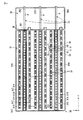
図4は、図2に示した二次電池装置1のうち、電池セル10を支持した第2支持枠30を上方から見た平面図である。なお、この図4においては、第1管路D1を形成するカバーの図示を省略している。
4 is a plan view of the
第2電池支持部31は、側壁35A、側壁35B、側壁35C、及び、仕切板36によって囲まれている。図中の破線で示した電池セル10は、第2支持枠30の第2電池支持部31に嵌め込まれている。これらの電池セル10の各々のセル端子11は、第2支持枠30から露出し、バスバー50と接続されている。図示した例では、バスバー50は、第1方向Xに延出し、第1方向Xに隣接する2つの電池セル10を電気に直列に接続している。第1方向Xに並んだ30個の電池セル10は、複数のバスバー50を介して直列に接続されている。
The second
第1管路D1を形成する凹所31Aは、第1電池支持部21において、リブ31Bとリブ31Cとの間に形成されている。凹所31Aの底部には、開口313が形成され、図示を省略した電池セルの防爆弁と対向している。第2方向Yに沿って延出した仕切板36には、第1方向に沿って延出した第1管路D1の各々と交差する位置に開口361が形成されている。
The
液溜部33は、側壁35A、側壁35B、側壁35D、及び、仕切板36によって囲まれ、これらによって囲まれた内側に底部33Bを有している。つまり、液溜部33は、上部が開口した箱状に形成されている。このような液溜部33には、液体を溜め置くことが可能である。なお、液溜部33は、一時的に溜め置いた液体を二次電池装置1の外部に排出するように構成されても良く、この場合、例えば、側壁35A、側壁35B、側壁35D、もしくは、底部33Bに排出口が設けられ、この排出口に接続されたドレインを介して液体を外部に排出可能である。
The
第2管路D2を構成するパイプPは、液溜部33を跨いで、仕切板36の開口361に嵌め込まれるとともに側壁35の開口351を貫通している。
The pipe P that constitutes the second pipeline D2 straddles the
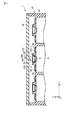
図5は、図2に示した二次電池装置1のうち、第2支持枠30の第2電池支持部31に支持された電池セル10を含む第2方向Yに沿った断面図である。
5 is a cross-sectional view along the second direction Y including the
第2電池支持部31は、電池セル10の上面10T側から嵌め込まれている。トップカバー40は、第2電池支持部31の上方を覆っている。図示したように、第2電池支持部31は、第2方向Yに沿って3列にわたって同様の構造を有している。
The second
すなわち、第2電池支持部31の開口311から露出した電池セル10のセル端子11、及び、開口312から露出した電池セル10のセル端子11は、それぞれバスバー50に接続されている。電池セル10の防爆弁12と対向する開口313と開口311との間にはリブ31Bが形成されている。また、電池セル10の防爆弁12と対向する開口313と開口312との間にはリブ31Cが形成されている。凹所31Aは、リブ31Bとリブ31Cとの間に形成されている。このような凹所31Aは、カバー32によって覆われている。このカバー32は、開口313を介して防爆弁12と向かい合っている。第1管路D1は、凹所31Aを形成するリブ31B及び31Cとカバー32とによって囲まれた空間に相当し、開口313と連通している。
That is, the
図示した例では、カバー32は、耐熱材料によって形成され、例えば、鉄、ニッケル、コバルト、モリブデン、チタン、バナジウム、アルミニウムの少なくとも1つを含む金属もしくはそれらを主材とした合金(例えばステンレスなど)、あるいは、セラミックによって形成されている。第2支持枠30は、たとえば、ポリカーボネイトなどのプラスチックによって形成されており、ここに示した例では、カバー32のみが耐熱材料によって形成されているが、第2支持枠30自体を上記の耐熱材料によって形成しても良い。この場合、第1管路D1を構成する全体が耐熱材料によって形成される。また、第2支持枠30に形成された凹所31Aの内壁のみが耐熱材料によって形成(例えば、プラスチック製の第2支持枠のうち凹所31Aの第1管路D1を形成する内面に耐熱材料を貼り付けるなど)されても良い。さらに、第1管路D1のみに留まらず、第2管路D2を構成するパイプPも含めて、排出管Dの全体が上記の耐熱材料によって形成されても良い。
In the illustrated example, the
第1管路D1の形態は、図5に示した例に限らない。以下に、図6及び図7を参照しながら、第1管路D1の他の形態について説明する。なお、図6及び図7では、図5に示した例と同一の構成については同一の参照符号を付して詳細な説明を省略する。 The form of the 1st pipe line D1 is not restricted to the example shown in FIG. Below, the other form of the 1st pipe line D1 is demonstrated, referring FIG.6 and FIG.7. 6 and 7, the same components as those in the example shown in FIG. 5 are denoted by the same reference numerals, and detailed description thereof is omitted.
図6に示す例では、カバー32は、YZ平面における断面がコの字型をなし、第1方向Xに沿って延在している。このようなカバー32は、リブ31Bとリブ31Cとの間に嵌め込まれている。このような例においては、第1管路D1は、凹所31Aとカバー32とによって囲まれた空間に相当し、防爆弁12と対向する開口313と連通している。このような例においても、カバー32は、上記したような耐熱材料によって形成されている。
In the example shown in FIG. 6, the
図7に示す例では、カバー32に代えて管状部材60を適用している。すなわち、この管状部材60は、YZ平面における断面がロの字型をなし、第1方向Xに沿って延在している。このような管状部材60は、凹所31Aを形成するリブ31Bとリブ31Cとの間に嵌め込まれている。また、この管状部材60には、凹所31Aに形成された開口313と対向する開口61が形成されている。このような例においては、第1管路D1は、凹所31Aに嵌め込まれた管状部材60の内部空間に相当し、開口61を介して防爆弁12と対向する開口313と連通している。このような例においても、管状部材60は、上記したような耐熱材料によって形成されている。
In the example shown in FIG. 7, a
いずれにしても、少なくとも第1管路D1における防爆弁12と向かい合う内壁は、上記した耐熱材料によって形成されており、他の部分については必ずしも耐熱材料によって形成されていなくても良い。カバー32の他の形態として、図示を省略するが、例えば、プラスチックなどで形成した平板状の下地材の表面に上記した耐熱材料を貼り付けた構成も適用可能である。
In any case, at least the inner wall facing the explosion-
図8は、図2に示した二次電池装置1のうち、第2支持枠30の第2電池支持部31及び液溜部33の第1方向Xに沿った断面図である。なお、図示した例は、図5に示した第1管路D1を適用した構成に相当する。
FIG. 8 is a cross-sectional view of the
仕切板36に形成された開口361は、第2電池支持部31の側から液溜部33の側まで第1方向Xに沿って貫通している。パイプPは、仕切板36の開口361に挿入されることによって接続されても良いが、図示した例では、液溜部33の側の開口361に形成されたリング状の突起362をくわえ込むことによって接続されている。このパイプPは、側壁35Dの開口351を貫通し、二次電池装置1の外部に引き出されており、排出口Doutに接続されている。このようなパイプPの内側に第2管路D2が形成される。
The
また、パイプPにおいて、液溜部33の直上の位置には、開孔DAが形成されている。このような開孔DAは、第2管路D2の重力方向下側に形成されており、液溜部33の底部33Bと向かい合っている。これにより、第2管路D2は、開孔DAを介して液溜部33と連通している。この液溜部33は、図示したように、トップカバー40によって密閉されていることが望ましい。
In the pipe P, an opening DA is formed at a position immediately above the
このような構成において、電池セル10の内部短絡や過充電などにより電池セル10が発熱し、電池セル10の内部圧力が設定値を越えると、防爆弁12から高温のガスが噴出する。噴出した高温のガスは、排出管Dを構成する第1管路D1から開口361を介して第2管路D2を経由し、排出口Doutから二次電池装置1の外部に排出される。
In such a configuration, when the
ここで、排出管Dのうち、第1管路D1における防爆弁12と向かい合うカバー32は、上記した耐熱材料によって形成されている。このため、防爆弁12から第3方向Zに沿って略直上に吹き上げた高温のガスによる第1管路D1の破損、特にカバー32の破損を抑制することが可能となり、排出管Dの途中から高温のガスが二次電池装置1の内部に漏れ出すことを防止できる。なお、少なくとも第1管路D1における防爆弁12と向かい合う内壁が上記した耐熱材料によって形成されていれば、上記の効果は得られる。
Here, in the discharge pipe D, the
また、高温のガスが温度の低い排出管Dや他の物質例えば熱伝導性の良好な部材に触れると、ガスが冷却されて液化し、液体である電解液へと変化する。この電解液についても、高温のガスと同様に、第1管路D1及び第2管路D2を経由して排出口Doutから二次電池装置1の外部に排出される。排出口Doutは、電池セル10の防爆弁12と同じ高さもしくはそれよりも低い位置つまり重力方向下側に設けられており、電解液は排出口Doutから二次電池装置1の外部へと排出される。
Further, when the high-temperature gas touches the discharge pipe D having a low temperature or another substance such as a member having good thermal conductivity, the gas is cooled and liquefied to change into a liquid electrolyte. Similarly to the high-temperature gas, this electrolytic solution is also discharged from the discharge port Dout to the outside of the
特に、本実施形態においては、第2管路D2が開孔DAを介して液溜部33と連通しているため、高温のガスとともに電池セル10から噴出した液状の電解液や、噴出した高温のガスが液化することによって生成された電解液は、排出口Doutに至る途中で開孔DAから液溜部33に排出される。このため、電解液が排出口Doutから排出されるまでの排出管Dの途中で詰まることが防止でき、電池セル10から噴出したガスの二次電池装置外までの排気経路を確保することが可能となる。なお、液溜部33は、本実施形態のように二次電池装置1の内部に設けるのではなく、二次電池装置1の外部に設けても良い。
In particular, in the present embodiment, since the second pipe line D2 communicates with the
また、液溜部33が密閉された構造であるため、液溜部33に排出された電解液が二次電池装置1の内部に漏れ出たり、二次電池装置1の周囲に飛散したりすることも防止できる。この液溜部33は、電池セル10の防爆弁12よりも低い位置つまり重力方向下側に設けられることが望ましく、この場合、排出管Dを通る電解液の開孔DAから液溜部33への排出が重力によって促進される。なお、液溜部33は、電池セル10の内部短絡や過充電で想定される電解液の噴出量よりも大きな容積を確保することがより望ましい。また、液溜部33には、スポンジ等で代表される液体吸収材料を配置し、後で電解液を吸収した液体吸収材料を回収するように構成してもよい。
Moreover, since the
これにより、二次電池装置1及びこの二次電池装置1を搭載した車両などの機器を安全に使用することが可能となる。
Thereby, it becomes possible to use the
次に、第2支持枠30などを省略した構成の二次電池装置1について説明する。
Next, the
図9に示した例では、二次電池装置1は、2つの電池セル101及び102と、排出管Dと、液溜部33とを備えている。電池セル101の正極端子11Pと電池セル102の負極端子11Nとは、バスバー50を介して電気的に接続されている。なお、電池セルは3個以上であっても良い。排出管Dは、2つの電池セル101及び102の上面10Tの上に配置されるとともに、ほぼ直角に折れ曲がり、電池セル102の側面10Sに沿って重力方向下側に向かって排出口Doutまで延出している。排出口Doutは、電池セル101及び102の上面10Tより重力方向下側に設けられている。液溜部33は、電池セル101及び102の上面10T及び排出口Doutより重力方向下側に設けられている。なお、詳述しないが、液溜部33には、液体吸収材料が配置されても良い。
In the example shown in FIG. 9, the
図10は、図9に示した二次電池装置1の分解斜視図である。
FIG. 10 is an exploded perspective view of the
電池セル101及び102の上面10Tには、それぞれ防爆弁12が設けられている。排出管Dについて、電池セル101及び102の上面10Tと向かい合う面には、2つの開口OPが形成されている。このような排出管Dは、開口OPのそれぞれが防爆弁12と対向するように設置される。液溜部33は、排出管Dの開口OPから排出口Doutまでの間の中途に設けられている。
Explosion-
このような構成によれば、電池セル101及び102の少なくとも一方から噴出された高温のガスが液化して生成された電解液は、排出管Dを通り、防爆弁12及び排出口Doutより低い位置の液溜部33に導かれる。このため、電解液は液溜部33に溜まる一方で、高温のガスの排出口Doutへの排出が妨げられず、排出口Doutから主としてガスのみが排出される。
According to such a configuration, the electrolytic solution generated by liquefying the high-temperature gas ejected from at least one of the
このように、電池セルから噴出した高温のガスについては排出管Dを通して排出口Doutから二次電池装置1の外部へ排出され、電解液については液溜部33に収納することで、二次電池装置1及びこの二次電池装置1を搭載した車両などの機器を安全に使用することが可能となる。
As described above, the high-temperature gas ejected from the battery cell is discharged from the discharge port Dout to the outside of the
なお、本実施形態においては、各種センサを設置しても良い。 In the present embodiment, various sensors may be installed.
例えば、排出管Dの内部または排出口Doutの外部などに温度センサを備えても良い。このような温度センサにより、瞬時に温度上昇を検知したのに基づいて電池セルから高温のガスが噴出したことを検知することができる。これにより、電池セル10の防爆弁12の開放を検知して二次電池装置1の使用を制限し、また充放電動作を停止することが可能になり、安全性を向上することができる。
For example, a temperature sensor may be provided inside the discharge pipe D or outside the discharge port Dout. With such a temperature sensor, it is possible to detect that hot gas has been ejected from the battery cell based on instantaneously detecting a temperature rise. Thereby, it is possible to detect the opening of the explosion-
また、排出管Dの内部または排出口Doutの外部などにガスセンサを備えても良い。ガスセンサとしては、酸素、水素、一酸化炭素、二酸化炭素などのガスを検出可能なセンサが適用可能である。このようなガスセンサにより、電解液が蒸発したガス成分を検知したのに基づいて電池セルからガスが噴出したことを検知することができる。これにより、電池セル10の防爆弁12の開放を検知して二次電池装置1の使用を制限し、また充放電動作を停止することが可能になる。
Further, a gas sensor may be provided inside the discharge pipe D or outside the discharge port Dout. As the gas sensor, a sensor capable of detecting a gas such as oxygen, hydrogen, carbon monoxide, carbon dioxide, or the like is applicable. With such a gas sensor, it is possible to detect that gas has been ejected from the battery cell based on the detection of the gas component evaporated from the electrolyte. Thereby, it is possible to limit the use of the
また、排出管Dの内部または液溜部33などに液体センサを備えても良い。このような液体センサにより、電解液を検知したのに基づいて電池セルからガスが放出され且つ液溜部33に電解液が蓄積されたことを検知することができる。これにより、電池セル10の防爆弁12の開放を検知して二次電池装置1の使用を制限し、また充放電動作を停止することが可能になる。
Further, a liquid sensor may be provided in the discharge pipe D or in the
また、本実施形態においては、排出管Dは、断熱材で覆っても良い。二次電池装置1の内部には、各電池セルの電圧を計測するための装置やまた電池セルの温度を計側する装置などが設けられ、また、複数の電線や部材が接続されている。二次電池装置1の内部に配置された電線などの各種部材は、必ずしも熱に強い材料で構築されているわけではない。このため、電池セルから高温のガスが噴出した場合には、排出管Dが高温となり、排出管Dに接した各種部材が溶けて機能を失う恐れがある。このため、排出管Dを断熱材で覆うことにより、高温のガスの熱を遮断する。これにより、二次電池装置1の内部の電線などの各種部材を熱から保護することができる。なお、排出管Dを断熱材で覆う代わりに、排出管Dの周囲に配置された敗戦などの各種部材を断熱材で覆っても良いし、排出管及び各種部材の双方を断熱材で覆っても良い。
In the present embodiment, the discharge pipe D may be covered with a heat insulating material. Inside the
なお、この発明は、上記実施形態そのものに限定されるものではなく、その実施の段階ではその要旨を逸脱しない範囲で構成要素を変形して具体化できる。また、上記実施形態に開示されている複数の構成要素の適宜な組み合せにより種々の発明を形成できる。例えば、実施形態に示される全構成要素から幾つかの構成要素を削除してもよい。更に、異なる実施形態に亘る構成要素を適宜組み合せてもよい。 In addition, this invention is not limited to the said embodiment itself, In the stage of implementation, it can change and implement a component within the range which does not deviate from the summary. In addition, various inventions can be formed by appropriately combining a plurality of constituent elements disclosed in the embodiment. For example, some components may be deleted from all the components shown in the embodiment. Furthermore, you may combine suitably the component covering different embodiment.
1…二次電池装置
10…電池セル
11…セル端子(11P…正極端子 11N…負極端子) 12…防爆弁
20…第1支持枠 21…電池支持部 22…回路収容部
30…第2支持枠 31…電池支持部 32…カバー 33…液溜部
60…管状部材 61…開口
D…排出管 D1…第1管路 D2…第2管路 Dout…排出口
P…パイプ DA…開孔 OP…開口
DESCRIPTION OF
Claims (4)
複数の前記電池セルの各々の防爆弁と対向する開口が形成されるとともに排出口まで延出した管路と、
前記管路の前記開口から前記排出口までの中途に設けられた液溜部と、
を備えたことを特徴とする二次電池装置。 A plurality of battery cells each having a surface provided with an explosion-proof valve;
A pipe line that is formed with an opening facing each explosion-proof valve of the plurality of battery cells and extends to the discharge port;
A liquid reservoir provided in the middle from the opening of the conduit to the outlet;
A secondary battery device comprising:
複数の前記電池セルの各々の面の前記電池セルの各々の前記防爆弁に対向する開口が形成された電池支持部を有する支持枠と、
前記電池支持部に位置し前記開口に連通する管路と、
前記電池支持部の外に位置し前記管路に連通する液溜部と、
を備えたことを特徴とする二次電池装置。 A plurality of battery cells each having a surface provided with an explosion-proof valve;
A support frame having a battery support portion formed with an opening facing each of the explosion-proof valves of each of the battery cells on each surface of the plurality of battery cells;
A conduit located in the battery support and communicating with the opening;
A liquid reservoir located outside the battery support and communicating with the conduit;
A secondary battery device comprising:
Priority Applications (1)
| Application Number | Priority Date | Filing Date | Title |
|---|---|---|---|
| JP2009286676A JP2011129372A (en) | 2009-12-17 | 2009-12-17 | Secondary battery device |
Applications Claiming Priority (1)
| Application Number | Priority Date | Filing Date | Title |
|---|---|---|---|
| JP2009286676A JP2011129372A (en) | 2009-12-17 | 2009-12-17 | Secondary battery device |
Publications (1)
| Publication Number | Publication Date |
|---|---|
| JP2011129372A true JP2011129372A (en) | 2011-06-30 |
Family
ID=44291750
Family Applications (1)
| Application Number | Title | Priority Date | Filing Date |
|---|---|---|---|
| JP2009286676A Pending JP2011129372A (en) | 2009-12-17 | 2009-12-17 | Secondary battery device |
Country Status (1)
| Country | Link |
|---|---|
| JP (1) | JP2011129372A (en) |
Cited By (18)
| Publication number | Priority date | Publication date | Assignee | Title |
|---|---|---|---|---|
| JP2013026091A (en) * | 2011-07-24 | 2013-02-04 | Toyota Industries Corp | Square secondary battery cell with cover |
| WO2013161655A1 (en) * | 2012-04-27 | 2013-10-31 | 三洋電機株式会社 | Power-supply device, vehicle provided therewith, and electricity-storage device |
| JP2014523622A (en) * | 2011-07-07 | 2014-09-11 | フェデラル エクスプレス コーポレイション | Battery cooling method and system |
| WO2014139710A1 (en) * | 2013-03-11 | 2014-09-18 | Robert Bosch Gmbh | Degassing system for battery modules |
| DE102014213936A1 (en) | 2014-07-17 | 2016-02-11 | Robert Bosch Gmbh | Device for increasing the safety when using battery systems |
| JP2017059476A (en) * | 2015-09-18 | 2017-03-23 | 積水化学工業株式会社 | Power storage system and building |
| US10003054B2 (en) | 2014-07-31 | 2018-06-19 | Gs Yuasa International Ltd. | Power source pack |
| WO2019148628A1 (en) * | 2018-01-31 | 2019-08-08 | 宁德时代新能源科技股份有限公司 | Battery module |
| JP2020077553A (en) * | 2018-11-08 | 2020-05-21 | 株式会社豊田自動織機 | Power storage device |
| JP2020187941A (en) * | 2019-05-15 | 2020-11-19 | 三菱自動車工業株式会社 | Abnormality detection device for battery pack |
| CN111969134A (en) * | 2019-05-20 | 2020-11-20 | 奥迪股份公司 | Energy accumulator, motor vehicle and housing cover arrangement |
| CN112331981A (en) * | 2019-10-15 | 2021-02-05 | 宁德时代新能源科技股份有限公司 | Battery packs and vehicles |
| JP2021132022A (en) * | 2020-02-21 | 2021-09-09 | 株式会社Gsユアサ | Power storage device |
| CN113506944A (en) * | 2021-09-07 | 2021-10-15 | 江苏翌强能源设备有限公司 | Safe explosion-proof new forms of energy electric energy storage device |
| CN114079110A (en) * | 2020-08-11 | 2022-02-22 | 北京好风光储能技术有限公司 | Large-scale horizontal energy storage battery and energy storage container |
| KR20220024852A (en) * | 2019-10-29 | 2022-03-03 | 티쎈크로프 마리네 지스템스 게엠베하 | Battery module with monitoring of thermal runaway of individual cells |
| CN115224434A (en) * | 2022-06-24 | 2022-10-21 | 湘潭大学 | A lithium-ion battery explosion-proof valve safety device |
| JP2025528860A (en) * | 2022-12-02 | 2025-09-02 | エルジー エナジー ソリューション リミテッド | Battery pack |
Citations (2)
| Publication number | Priority date | Publication date | Assignee | Title |
|---|---|---|---|---|
| JPS5551817U (en) * | 1978-09-30 | 1980-04-05 | ||
| JP2007012485A (en) * | 2005-06-30 | 2007-01-18 | Sanyo Electric Co Ltd | Battery with cap and power supply |
-
2009
- 2009-12-17 JP JP2009286676A patent/JP2011129372A/en active Pending
Patent Citations (2)
| Publication number | Priority date | Publication date | Assignee | Title |
|---|---|---|---|---|
| JPS5551817U (en) * | 1978-09-30 | 1980-04-05 | ||
| JP2007012485A (en) * | 2005-06-30 | 2007-01-18 | Sanyo Electric Co Ltd | Battery with cap and power supply |
Cited By (31)
| Publication number | Priority date | Publication date | Assignee | Title |
|---|---|---|---|---|
| JP2014523622A (en) * | 2011-07-07 | 2014-09-11 | フェデラル エクスプレス コーポレイション | Battery cooling method and system |
| JP2013026091A (en) * | 2011-07-24 | 2013-02-04 | Toyota Industries Corp | Square secondary battery cell with cover |
| WO2013161655A1 (en) * | 2012-04-27 | 2013-10-31 | 三洋電機株式会社 | Power-supply device, vehicle provided therewith, and electricity-storage device |
| CN105027323B (en) * | 2013-03-11 | 2020-03-13 | 罗伯特·博世有限公司 | Exhaust system for battery module |
| WO2014139710A1 (en) * | 2013-03-11 | 2014-09-18 | Robert Bosch Gmbh | Degassing system for battery modules |
| CN105027323A (en) * | 2013-03-11 | 2015-11-04 | 罗伯特·博世有限公司 | Degassing system for battery modules |
| DE102014213936A1 (en) | 2014-07-17 | 2016-02-11 | Robert Bosch Gmbh | Device for increasing the safety when using battery systems |
| US10003054B2 (en) | 2014-07-31 | 2018-06-19 | Gs Yuasa International Ltd. | Power source pack |
| JP2017059476A (en) * | 2015-09-18 | 2017-03-23 | 積水化学工業株式会社 | Power storage system and building |
| WO2019148628A1 (en) * | 2018-01-31 | 2019-08-08 | 宁德时代新能源科技股份有限公司 | Battery module |
| JP2020077553A (en) * | 2018-11-08 | 2020-05-21 | 株式会社豊田自動織機 | Power storage device |
| JP7107819B2 (en) | 2018-11-08 | 2022-07-27 | 株式会社豊田自動織機 | power storage device |
| JP2020187941A (en) * | 2019-05-15 | 2020-11-19 | 三菱自動車工業株式会社 | Abnormality detection device for battery pack |
| JP7328614B2 (en) | 2019-05-15 | 2023-08-17 | 三菱自動車工業株式会社 | Abnormality detection device for battery pack |
| CN111969134A (en) * | 2019-05-20 | 2020-11-20 | 奥迪股份公司 | Energy accumulator, motor vehicle and housing cover arrangement |
| US11362397B2 (en) * | 2019-05-20 | 2022-06-14 | Audi Ag | Energy storage device, motor vehicle, and housing cover assembly |
| US11387519B2 (en) | 2019-10-15 | 2022-07-12 | Contemporary Amperex Technology Co., Limited | Battery pack and vehicle |
| CN112331981B (en) * | 2019-10-15 | 2021-09-17 | 宁德时代新能源科技股份有限公司 | Battery pack and vehicle |
| US12166226B2 (en) | 2019-10-15 | 2024-12-10 | Contemporary Amperex Technology (Hong Kong) Limited | Battery pack and vehicle |
| CN112331981A (en) * | 2019-10-15 | 2021-02-05 | 宁德时代新能源科技股份有限公司 | Battery packs and vehicles |
| KR20220024852A (en) * | 2019-10-29 | 2022-03-03 | 티쎈크로프 마리네 지스템스 게엠베하 | Battery module with monitoring of thermal runaway of individual cells |
| KR102797592B1 (en) * | 2019-10-29 | 2025-04-18 | 티쎈크로프 마리네 지스템스 게엠베하 | Battery module with monitoring of thermal runaway of individual cells |
| JP2021132022A (en) * | 2020-02-21 | 2021-09-09 | 株式会社Gsユアサ | Power storage device |
| JP7581630B2 (en) | 2020-02-21 | 2024-11-13 | 株式会社Gsユアサ | Power storage device |
| CN114079110B (en) * | 2020-08-11 | 2023-11-14 | 好风光储能技术(成都)有限公司 | Large-scale horizontal energy storage battery and energy storage container |
| CN114079110A (en) * | 2020-08-11 | 2022-02-22 | 北京好风光储能技术有限公司 | Large-scale horizontal energy storage battery and energy storage container |
| CN113506944A (en) * | 2021-09-07 | 2021-10-15 | 江苏翌强能源设备有限公司 | Safe explosion-proof new forms of energy electric energy storage device |
| CN113506944B (en) * | 2021-09-07 | 2021-11-12 | 江苏翌强能源设备有限公司 | Safe explosion-proof new forms of energy electric energy storage device |
| CN115224434B (en) * | 2022-06-24 | 2023-08-25 | 湘潭大学 | A lithium-ion battery explosion-proof valve safety device |
| CN115224434A (en) * | 2022-06-24 | 2022-10-21 | 湘潭大学 | A lithium-ion battery explosion-proof valve safety device |
| JP2025528860A (en) * | 2022-12-02 | 2025-09-02 | エルジー エナジー ソリューション リミテッド | Battery pack |
Similar Documents
| Publication | Publication Date | Title |
|---|---|---|
| JP2011129372A (en) | Secondary battery device | |
| CN101212032B (en) | Battery pack | |
| CN103081164B (en) | Battery module | |
| EP2597700B1 (en) | Battery pack | |
| JP6025030B2 (en) | Power storage device | |
| JP6157460B2 (en) | Power storage module | |
| JP6798982B2 (en) | Battery system and car | |
| US8053098B2 (en) | Power storage unit that effectively controls pressure and vehicle | |
| JP2023537636A (en) | A battery pack that reduces the temperature of venting gas and has a structure that blocks external discharge of sparks. | |
| JP7271686B2 (en) | battery pack | |
| JP7326494B2 (en) | Battery module including busbar plate, battery pack and electronic device including same | |
| CN105518898B (en) | Battery module | |
| CN103262295B (en) | Electrical storage device | |
| ES3014080T3 (en) | Battery module, battery rack, and power storage device | |
| JP5929670B2 (en) | Battery module and battery pack | |
| US20240047820A1 (en) | Battery module having structure for blocking oxygen inflow during thermal propagation | |
| CN102696132A (en) | Battery module | |
| JPWO2019064924A1 (en) | Electrical connection member storage case and battery module | |
| JP2010015953A (en) | Energy storage device and vehicle | |
| JP7852515B2 (en) | Energy storage device | |
| JP2007273353A (en) | Battery structure | |
| KR102772824B1 (en) | Battery pack with improved safety | |
| KR102754518B1 (en) | Battery pack with improved safety | |
| WO2026007942A1 (en) | Battery pack and electric device | |
| KR102952461B1 (en) | Battery Module Comprising Busbar Plate and Battery Pack Having the Same and Electric Device |
Legal Events
| Date | Code | Title | Description |
|---|---|---|---|
| A621 | Written request for application examination |
Free format text: JAPANESE INTERMEDIATE CODE: A621 Effective date: 20121210 |
|
| A977 | Report on retrieval |
Free format text: JAPANESE INTERMEDIATE CODE: A971007 Effective date: 20131113 |
|
| A131 | Notification of reasons for refusal |
Free format text: JAPANESE INTERMEDIATE CODE: A131 Effective date: 20131126 |
|
| RD04 | Notification of resignation of power of attorney |
Free format text: JAPANESE INTERMEDIATE CODE: A7424 Effective date: 20131205 |
|
| RD04 | Notification of resignation of power of attorney |
Free format text: JAPANESE INTERMEDIATE CODE: A7424 Effective date: 20131212 |
|
| RD04 | Notification of resignation of power of attorney |
Free format text: JAPANESE INTERMEDIATE CODE: A7424 Effective date: 20131219 |
|
| RD04 | Notification of resignation of power of attorney |
Free format text: JAPANESE INTERMEDIATE CODE: A7424 Effective date: 20131226 |
|
| RD04 | Notification of resignation of power of attorney |
Free format text: JAPANESE INTERMEDIATE CODE: A7424 Effective date: 20140109 |
|
| RD04 | Notification of resignation of power of attorney |
Free format text: JAPANESE INTERMEDIATE CODE: A7424 Effective date: 20140116 |
|
| A02 | Decision of refusal |
Free format text: JAPANESE INTERMEDIATE CODE: A02 Effective date: 20140318 |