JP2011107589A - Stereoscopic display apparatus - Google Patents
Stereoscopic display apparatus Download PDFInfo
- Publication number
- JP2011107589A JP2011107589A JP2009264985A JP2009264985A JP2011107589A JP 2011107589 A JP2011107589 A JP 2011107589A JP 2009264985 A JP2009264985 A JP 2009264985A JP 2009264985 A JP2009264985 A JP 2009264985A JP 2011107589 A JP2011107589 A JP 2011107589A
- Authority
- JP
- Japan
- Prior art keywords
- dimensional display
- image
- lens
- light
- polarization state
- Prior art date
- Legal status (The legal status is an assumption and is not a legal conclusion. Google has not performed a legal analysis and makes no representation as to the accuracy of the status listed.)
- Pending
Links
Images


Classifications
-
- H—ELECTRICITY
- H04—ELECTRIC COMMUNICATION TECHNIQUE
- H04N—PICTORIAL COMMUNICATION, e.g. TELEVISION
- H04N13/00—Stereoscopic video systems; Multi-view video systems; Details thereof
- H04N13/30—Image reproducers
- H04N13/356—Image reproducers having separate monoscopic and stereoscopic modes
-
- G—PHYSICS
- G02—OPTICS
- G02B—OPTICAL ELEMENTS, SYSTEMS OR APPARATUS
- G02B30/00—Optical systems or apparatus for producing three-dimensional [3D] effects, e.g. stereoscopic images
- G02B30/20—Optical systems or apparatus for producing three-dimensional [3D] effects, e.g. stereoscopic images by providing first and second parallax images to an observer's left and right eyes
- G02B30/22—Optical systems or apparatus for producing three-dimensional [3D] effects, e.g. stereoscopic images by providing first and second parallax images to an observer's left and right eyes of the stereoscopic type
- G02B30/25—Optical systems or apparatus for producing three-dimensional [3D] effects, e.g. stereoscopic images by providing first and second parallax images to an observer's left and right eyes of the stereoscopic type using polarisation techniques
-
- G—PHYSICS
- G02—OPTICS
- G02B—OPTICAL ELEMENTS, SYSTEMS OR APPARATUS
- G02B30/00—Optical systems or apparatus for producing three-dimensional [3D] effects, e.g. stereoscopic images
- G02B30/20—Optical systems or apparatus for producing three-dimensional [3D] effects, e.g. stereoscopic images by providing first and second parallax images to an observer's left and right eyes
- G02B30/26—Optical systems or apparatus for producing three-dimensional [3D] effects, e.g. stereoscopic images by providing first and second parallax images to an observer's left and right eyes of the autostereoscopic type
- G02B30/27—Optical systems or apparatus for producing three-dimensional [3D] effects, e.g. stereoscopic images by providing first and second parallax images to an observer's left and right eyes of the autostereoscopic type involving lenticular arrays
- G02B30/28—Optical systems or apparatus for producing three-dimensional [3D] effects, e.g. stereoscopic images by providing first and second parallax images to an observer's left and right eyes of the autostereoscopic type involving lenticular arrays involving active lenticular arrays
-
- H—ELECTRICITY
- H04—ELECTRIC COMMUNICATION TECHNIQUE
- H04N—PICTORIAL COMMUNICATION, e.g. TELEVISION
- H04N13/00—Stereoscopic video systems; Multi-view video systems; Details thereof
- H04N13/30—Image reproducers
- H04N13/302—Image reproducers for viewing without the aid of special glasses, i.e. using autostereoscopic displays
- H04N13/305—Image reproducers for viewing without the aid of special glasses, i.e. using autostereoscopic displays using lenticular lenses, e.g. arrangements of cylindrical lenses
-
- H—ELECTRICITY
- H04—ELECTRIC COMMUNICATION TECHNIQUE
- H04N—PICTORIAL COMMUNICATION, e.g. TELEVISION
- H04N13/00—Stereoscopic video systems; Multi-view video systems; Details thereof
- H04N13/30—Image reproducers
- H04N13/332—Displays for viewing with the aid of special glasses or head-mounted displays [HMD]
- H04N13/337—Displays for viewing with the aid of special glasses or head-mounted displays [HMD] using polarisation multiplexing
Landscapes
- Physics & Mathematics (AREA)
- Engineering & Computer Science (AREA)
- Multimedia (AREA)
- Signal Processing (AREA)
- General Physics & Mathematics (AREA)
- Optics & Photonics (AREA)
- Mechanical Light Control Or Optical Switches (AREA)
- Testing, Inspecting, Measuring Of Stereoscopic Televisions And Televisions (AREA)
- Stereoscopic And Panoramic Photography (AREA)
- Liquid Crystal (AREA)
Abstract
【課題】2次元表示と3次元表示とを切り替え可能であると共に、3次元表示の方式を裸眼方式と眼鏡方式とに切り替えることができるようにする。
【解決手段】2次元表示部(表示パネル2)に2次元表示用の画像表示を行った状態で可変レンズアレイ素子1によるレンズ効果をオフ状態にすることで2次元表示を行う。2次元表示部に3次元表示用の左眼用画像と右眼用画像とを表示した状態で可変レンズアレイ素子1によるレンズ効果をオン状態にすることで、裸眼方式による3次元表示を行う。2次元表示部に3次元表示用の左眼用画像と右眼用画像とを表示した状態で可変レンズアレイ素子1によるレンズ効果をオフ状態にし、偏光状態変換部5によって左眼用画像による光を第1の偏光状態にすると共に右眼用画像による光を第2の偏光状態に変換して出射し、変換後の左眼用画像と右眼用画像とを偏光眼鏡を介して観察することで眼鏡方式による3次元表示を行う。
【選択図】図1To switch between a two-dimensional display and a three-dimensional display and to switch a three-dimensional display method between a naked eye method and a glasses method.
Two-dimensional display is performed by turning off a lens effect by a variable lens array element in a state where an image for two-dimensional display is displayed on a two-dimensional display unit (display panel). By turning on the lens effect of the variable lens array element 1 while displaying the left-eye image and the right-eye image for three-dimensional display on the two-dimensional display unit, three-dimensional display by the naked eye method is performed. The lens effect by the variable lens array element 1 is turned off in a state where the left-eye image and the right-eye image for three-dimensional display are displayed on the two-dimensional display unit, and the light from the left-eye image is displayed by the polarization state conversion unit 5. Is converted into the first polarization state, the light from the right-eye image is converted into the second polarization state and emitted, and the converted left-eye image and right-eye image are observed through the polarizing glasses. 3D display is performed by the glasses method.
[Selection] Figure 1
Description
本発明は、両眼視差を利用した3次元表示を行う立体表示装置に関する。 The present invention relates to a stereoscopic display device that performs three-dimensional display using binocular parallax.
従来より、観察者の左眼と右眼とに視差のある別々の画像(視差画像)を呈示することで立体視を実現する立体表示装置が知られている。このような立体表示装置の方式としては、眼鏡方式と裸眼方式とがある。眼鏡方式は、立体視用の特殊な眼鏡を装着することで立体視を実現する。特許文献3には、立体視用の眼鏡として、偏光フィルタを用いる方式が開示されている。
2. Description of the Related Art Conventionally, stereoscopic display devices that realize stereoscopic viewing by presenting separate images (parallax images) with parallax in the left eye and right eye of an observer are known. As a method of such a stereoscopic display device, there are a spectacle method and a naked eye method. The glasses method realizes stereoscopic viewing by wearing special glasses for stereoscopic viewing.
一方、裸眼方式は、特殊な眼鏡を装着することなく、裸眼で立体視が可能なものであり、例えばパララックスバリア方式やレンチキュラ方式が知られている。パララックスバリア方式では、視差分離手段としてパララックスバリアと呼ばれる構造物を2次元表示パネルに対向配置し、2次元表示パネルに表示された左右の視差画像をパララックスバリアによって水平方向に視差分離することで立体視が行われる。レンチキュラ方式では、視差分離手段としてレンチキュラレンズを2次元表示パネルに対向配置し、2次元表示パネルに表示された左右の視差画像をレンチキュラレンズによって水平方向に視差分離することで立体視が行われる。また、液晶レンズや液体レンズによる可変式のレンチキュラレンズを用いることで、2次元表示とレンチキュラ方式による3次元表示とを切り替え可能にした表示装置が知られている(特許文献1,2参照)。 On the other hand, the naked-eye method enables stereoscopic viewing with the naked eye without wearing special glasses. For example, a parallax barrier method and a lenticular method are known. In the parallax barrier method, a structure called a parallax barrier is disposed as a parallax separation unit so as to face a two-dimensional display panel, and left and right parallax images displayed on the two-dimensional display panel are separated in a horizontal direction by the parallax barrier. Thus, stereoscopic viewing is performed. In the lenticular method, stereoscopic viewing is performed by disposing a lenticular lens as a parallax separating unit facing a two-dimensional display panel and separating the left and right parallax images displayed on the two-dimensional display panel in the horizontal direction by the lenticular lens. There is also known a display device that can switch between two-dimensional display and three-dimensional display using a lenticular method by using a variable lenticular lens using a liquid crystal lens or a liquid lens (see Patent Documents 1 and 2).
しかしながら、パララックスバリア方式やレンチキュラ方式の場合、立体視できる範囲(視域)が狭いため、観賞する位置や距離が限定され、多人数で同時に観賞できないという問題がある。一方、眼鏡方式の場合、観賞する位置や距離の制約は小さく、多人数で同時に観賞できるものの、専用の眼鏡が必要になるという問題がある。従って、1つの立体表示装置で、観賞人数や視聴環境に応じて3次元表示の方式を切り替えることができれば便利である。 However, in the case of the parallax barrier method or the lenticular method, since the range (viewing area) in which stereoscopic viewing is possible is narrow, there is a problem that the viewing position and distance are limited, and a large number of people cannot watch at the same time. On the other hand, in the case of the glasses system, there are problems that restrictions on the viewing position and distance are small and that a large number of people can watch at the same time, but dedicated glasses are required. Therefore, it is convenient if one 3D display device can switch the 3D display method according to the number of viewers and the viewing environment.
本発明はかかる問題点に鑑みてなされたもので、その目的は、2次元表示と3次元表示とを切り替え可能であると共に、3次元表示の方式を裸眼方式と眼鏡方式とに切り替えることができるようにした立体表示装置を提供することにある。 The present invention has been made in view of such problems, and the object thereof is to switch between two-dimensional display and three-dimensional display and to switch the three-dimensional display method between the naked eye method and the glasses method. An object of the present invention is to provide such a stereoscopic display device.
本発明による立体表示装置は、2次元表示用の画像表示と3次元表示用の画像表示とを行い、3次元表示用の画像表示を行う場合には、互いに視差のある左眼用画像と右眼用画像とを空間的に分割して1画面内に表示する2次元表示部と、2次元表示部に対向配置され、2次元表示部に表示された画像による光を、所定の画像領域ごとに互いに偏光状態が異なる第1の偏光状態と第2の偏光状態とに変換する偏光状態変換部と、偏光状態変換部の光出射側、または2次元表示部と偏光状態変換部との間に配置されると共に、2次元表示部に表示された画像による光線に対するレンズ効果をオン状態とオフ状態とに可変制御することが可能に構成された可変レンズアレイ素子と、第1の偏光状態とされた光のみを透過する第1の偏光フィルタと第2の偏光状態とされた光のみを透過する第2の偏光フィルタとを有する偏光眼鏡とを備えたものである。
そして、2次元表示部に2次元表示用の画像表示を行った状態で可変レンズアレイ素子によるレンズ効果をオフ状態にし、2次元表示部からの表示画像光を可変レンズアレイ素子で屈折させることなく透過させることで2次元表示を行い、2次元表示部に3次元表示用の左眼用画像と右眼用画像とを表示した状態で可変レンズアレイ素子によるレンズ効果をオン状態にし、2次元表示部に表示された左眼用画像による光線と右眼用画像による光線とを裸眼による立体視が可能となるように屈折させて光学的に分離することで、裸眼方式による3次元表示を行うようにしたものである。さらに、2次元表示部に3次元表示用の左眼用画像と右眼用画像とを表示した状態で可変レンズアレイ素子によるレンズ効果をオフ状態にし、可変レンズアレイ素子では左眼用画像による光線と右眼用画像による光線とを屈折させることなく透過させる一方、偏光状態変換部では左眼用画像による光を第1の偏光状態にすると共に右眼用画像による光を第2の偏光状態となるように変換して出射し、その変換後の左眼用画像と右眼用画像とを偏光眼鏡を介して観察することで眼鏡方式による3次元表示を行うようにしたものである。
The stereoscopic display device according to the present invention performs image display for two-dimensional display and image display for three-dimensional display, and when performing image display for three-dimensional display, a left-eye image having a parallax and a right image are displayed. A two-dimensional display unit that spatially divides an ophthalmic image and displays it in one screen, and light from the image displayed on the two-dimensional display unit that is disposed opposite to the two-dimensional display unit, for each predetermined image area A polarization state converter that converts the first and second polarization states having different polarization states from each other, and a light exit side of the polarization state converter, or between the two-dimensional display unit and the polarization state converter. A variable lens array element configured to be variably controlled between an on state and an off state, and a first polarization state. A first polarizing filter that transmits only the reflected light; It is obtained by a polarized glasses and a second polarization filter which transmits only light with a polarization state of two.
Then, the lens effect of the variable lens array element is turned off in a state where the image for two-dimensional display is displayed on the two-dimensional display unit, and the display image light from the two-dimensional display unit is not refracted by the variable lens array element. 2D display is performed by transmitting, and the lens effect by the variable lens array element is turned on while the left-eye image and the right-eye image for 3D display are displayed on the 2D display unit. 3D display by the naked-eye method is performed by refracting and optically separating the light beam from the left-eye image and the light beam from the right-eye image displayed on the screen so that stereoscopic vision by the naked eye is possible It is a thing. Further, the lens effect by the variable lens array element is turned off in a state where the left-eye image and the right-eye image for three-dimensional display are displayed on the two-dimensional display unit. And the light from the right-eye image are transmitted without being refracted, while the polarization state converting unit changes the light from the left-eye image to the first polarization state and the light from the right-eye image to the second polarization state. In this way, the image is converted and emitted, and the converted image for the left eye and the image for the right eye are observed through polarized glasses, thereby performing three-dimensional display by the glasses method.
本発明による立体表示装置では、2次元表示部に2次元表示用の画像表示を行った状態で可変レンズアレイ素子によるレンズ効果をオフ状態にすることで、2次元表示が行われる。また、2次元表示部に3次元表示用の左眼用画像と右眼用画像とを表示した状態で可変レンズアレイ素子によるレンズ効果をオン状態にすることで、裸眼方式による3次元表示が行われる。また、2次元表示部に3次元表示用の左眼用画像と右眼用画像とを表示した状態で可変レンズアレイ素子によるレンズ効果をオフ状態にし、かつ、偏光状態変換部によって左眼用画像による光を第1の偏光状態にすると共に右眼用画像による光を第2の偏光状態となるように変換して出射し、その変換後の左眼用画像と右眼用画像とを偏光眼鏡を介して観察することで眼鏡方式による3次元表示が行われる。 In the stereoscopic display device according to the present invention, two-dimensional display is performed by turning off the lens effect of the variable lens array element in a state where an image for two-dimensional display is displayed on the two-dimensional display unit. In addition, when the left-eye image and the right-eye image for three-dimensional display are displayed on the two-dimensional display unit, the lens effect by the variable lens array element is turned on, thereby performing three-dimensional display by the naked eye method. Is called. Further, the left-eye image and the right-eye image for three-dimensional display are displayed on the two-dimensional display unit, the lens effect by the variable lens array element is turned off, and the left-eye image is displayed by the polarization state conversion unit. The light of the right eye is converted into the first polarization state and the light of the right eye image is converted and emitted so as to be in the second polarization state, and the converted left eye image and right eye image are polarized glasses. 3D display by the glasses method is performed by observing through the screen.
本発明の立体表示装置によれば、偏光状態変換部と可変レンズアレイ素子と偏光眼鏡とを適切に組み合わせると共に、2次元表示部に表示された画像内容に応じて可変レンズアレイ素子のレンズ効果をオン状態とオフ状態とに可変制御するようにしたので、2次元表示と3次元表示とを切り替え可能であると共に、3次元表示の方式を裸眼方式と眼鏡方式とに切り替えることができる。これにより、視聴環境に適した3次元表示が可能となる。例えば観賞する人数が1人または2人以上の少数の場合には、裸眼方式による3次元表示で対応可能であり、この場合、3次元表示用の専用眼鏡が不要となる。また、眼鏡方式による3次元表示を行うことで、多人数での観賞や見る位置を自由に選んでの観賞が可能となる。 According to the stereoscopic display device of the present invention, the polarization state conversion unit, the variable lens array element, and the polarizing glasses are appropriately combined, and the lens effect of the variable lens array element can be obtained according to the image content displayed on the two-dimensional display unit. Since the on-state and the off-state are variably controlled, the two-dimensional display and the three-dimensional display can be switched, and the three-dimensional display system can be switched between the naked eye system and the eyeglass system. As a result, three-dimensional display suitable for the viewing environment is possible. For example, when the number of viewers is one or a small number of two or more, it can be handled by three-dimensional display by the naked eye method. In this case, dedicated glasses for three-dimensional display are not necessary. In addition, by performing a three-dimensional display using a glasses method, viewing by a large number of people and viewing by freely selecting a viewing position can be performed.
以下、本発明の実施の形態について図面を参照して詳細に説明する。 Hereinafter, embodiments of the present invention will be described in detail with reference to the drawings.
<第1の実施の形態>
[立体表示装置の基本構成]
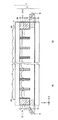
図1は、本発明の第1の実施の形態に係る立体表示装置の全体構成を示している。この立体表示装置は、2次元表示モードと3次元表示モードとの2つの表示モードへの切り替えが可能であると共に、さらに、3次元表示モードを裸眼方式と眼鏡方式とに切り替えることが可能となっている。図4は、この立体表示装置において眼鏡方式で3次元表示を行っている状態を模式的に示している。図5は裸眼方式で3次元表示を行っている状態を模式的に示している。この立体表示装置は、2次元表示部としての表示パネル2と、この表示パネル2の表示面側に対向するように配置された偏光状態変換部5と可変レンズアレイ素子1とを備えている。また、図4に示したように、眼鏡方式で3次元表示を行う際に使用される偏光眼鏡40を備えている。
<First Embodiment>
[Basic configuration of stereoscopic display device]
FIG. 1 shows the overall configuration of a stereoscopic display device according to the first embodiment of the present invention. This stereoscopic display device can be switched between two display modes of a two-dimensional display mode and a three-dimensional display mode, and can further switch the three-dimensional display mode between a naked eye method and a glasses method. ing. FIG. 4 schematically shows a state in which a three-dimensional display is performed by the glasses method in this stereoscopic display device. FIG. 5 schematically shows a state where three-dimensional display is performed by the naked eye method. The stereoscopic display device includes a
表示パネル2は、複数の画素がマトリクス状に配置され2次元的な画像表示を行うものである。表示パネル2は、表示した画像による光を特定の方向に偏光した直線偏光の状態で出射するように構成されている。図1等では、表示パネル2から、水平方向(図1のX軸方向)に直線偏光した状態で表示画像光が出射されている例を示している。表示パネル2は、例えば透過型の液晶表示ディスプレイで構成されている。液晶ディスプレイの場合、液晶パネル本体を、例えば互いの偏光方向がクロスニコルとなるように2枚の偏光板で挟んだ構造となっており、表示画像光は出射側の偏光板の偏光方向で規定される方向に偏光している。なお、ディスプレイの構造自体が直線偏光の光を出射するものでなくとも、表示面に対向するように偏光板を配置すれば他の構造のディスプレイを用いても良い。例えば、表示パネル2として、有機EL(Electro-Luminescence)ディスプレイ、またはプラズマディスプレイパネルなどを偏光板と組み合わせて用いるようにしても良い。
The
表示パネル2は、2次元表示用の画像表示と3次元表示用の画像表示とを行うようになっている。2次元表示用の画像表示は、通常の2次元画像データに基づいて2次元マトリクス表示を行う。3次元表示を行う場合には3次元画像データに基づく表示を行う。3次元画像データとは、例えば、3次元表示における複数の視野角方向に対応した複数の視差画像を含むデータである。本実施の形態では、3次元画像データとして、互いに視差のある左眼用画像Lと右眼用画像Rとを含む視差画像データを用いる。表示パネル2は、3次元表示用の画像表示を行う場合には、互いに視差のある左眼用画像Lと右眼用画像Rとを空間的に分割して1画面内に合成して表示するようになっている。表示パネル2は、裸眼方式による3次元表示を行う場合には、図5に示したように、左眼用画像と右眼用画像とが水平方向に交互に現れるような画像表示を行うようになっている。眼鏡方式による3次元表示を行う場合には、図4に示したように、左眼用画像Lと右眼用画像Rとが垂直方向に交互に現れるような画像表示を行うようになっている。
The
偏光状態変換部5は、表示パネル2に表示された画像による光を、所定の画像領域ごとに互いに偏光状態が異なる第1の偏光状態と第2の偏光状態とに変換するものである。偏光状態変換部5は、表示パネル2に表示された画像による光を、眼鏡方式による3次元表示を行う場合における左眼用画像Lと右眼用画像Rとに対応する領域ごとに、垂直方向に交互に偏光状態の変換を行うようになっている。
The polarization
偏光状態変換部5は、第1の位相差板5Aと第2の位相差板5Bとを有している。第1の位相差板5Aと第2の位相差板5Bは、水平方向に延在する短冊状の位相差板であり、垂直方向に交互に複数配置されている。第1の位相差板5Aは、表示パネル2において眼鏡方式による3次元表示を行う場合に表示する左眼用画像Lの表示領域に対応する位置に設けられている。第2の位相差板5Bは、表示パネル2において眼鏡方式による3次元表示を行う場合に表示する右眼用画像Rの表示領域に対応する位置に設けられている。
The polarization
第1の位相差板5Aは、表示パネル2から出射された直線偏光の光を第1の円偏光に変換して第1の偏光状態として出射するようになっている。第2の位相差板5Bは、直線偏光の光を第1の円偏光とは回転方向が異なる第2の円偏光に変換して第2の偏光状態として出射するようになっている。より具体的には、第1の位相差板5Aと第2の位相差板5Bは、1/4波長板で構成されている。そして、第1の位相差板5Aの遅相軸A1と第2の位相差板5Bの遅相軸B1とが、表示パネル2から出射された直線偏光の方向(X軸方向)に対して、互いに異なる方向に45°傾いた状態とされている。例えば、第1の位相差板5Aの遅相軸A1が左肩上がりに45°傾いた状態、第2の位相差板5Bの遅相軸B1が右肩上がりに45°傾いた状態とされている。これにより、第1の位相差板5Aでは表示パネル2から出射された直線偏光の光を左回りの円偏光に変換し、第2の位相差板5Bでは表示パネル2から出射された直線偏光の光を右回りの円偏光に変換するようになっている。第1の位相差板5Aと第2の位相差板5Bは、眼鏡方式による3次元表示を行う場合に表示する左眼用画像Lと右眼用画像Rとに対応する領域に設けられているので、結果的に、左眼用画像Lは左回りの円偏光、右眼用画像Rは左回りの円偏光に変換される。
The
偏光眼鏡40は、左眼9L用の第1の偏光フィルタ41Lと、右眼9R用の第2の偏光フィルタ41Rとを有している。第1の偏光フィルタ41Lは、偏光状態変換部5の第1の位相差板5Aによって第1の偏光状態とされた光のみを透過するものである。第2の偏光フィルタ41Rは、第2の位相差板5Bによって第2の偏光状態とされた光のみを透過するものである。
The
[可変レンズアレイ素子1の全体構成]
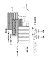
図2(A),(B)は可変レンズアレイ素子1の構造を示している。可変レンズアレイ素子1は、表示モードに応じてレンズ効果を電気的にオン・オフ制御することで、表示パネル2からの光線の通過状態を選択的に変化させるものである。図2(A)は可変レンズアレイ素子1を全体としてレンズ効果をオフした状態、図2(B)は可変レンズアレイ素子1を全体としてレンズ効果をオンにした状態での構成を示している。可変レンズアレイ素子1は、表示パネル2に対向する側から順に、液体レンチキュラレンズ3と、固定レンチキュラレンズ4とを備えている。液体レンチキュラレンズ3は、電気的にレンズ効果のオン・オフ制御が可能な複数の可変レンズを有している。
[Overall Configuration of Variable Lens Array Element 1]
2A and 2B show the structure of the variable lens array element 1. FIG. The variable lens array element 1 selectively changes the passage state of light rays from the
固定レンチキュラレンズ4は、複数の可変レンズに対応して設けられた複数の固定レンズを有し、複数の固定レンズがそれぞれ、対応する可変レンズのレンズ効果がオン状態となったときのそのレンズ効果を相殺するような屈折力を有している。より具体的には、固定レンチキュラレンズ4は、固定レンズとしてシリンドリカルレンズ(円筒レンズ)4Aを複数、並列配置したシリンドリカルレンズアレイの構成となっている。固定レンチキュラレンズ4において、各シリンドリカルレンズ4Aは、表示パネル2の表示面に対して縦方向に延在し、左右方向に正の屈折力を有するように配置されている。各シリンドリカルレンズ4Aの横方向のレンズピッチは、表示パネル2に表示する左眼用画像Lと右眼用画像Rとの1組分の画素幅(例えば2画素)の大きさに対応している。
The fixed lenticular lens 4 has a plurality of fixed lenses provided corresponding to the plurality of variable lenses, and each of the plurality of fixed lenses has its lens effect when the lens effect of the corresponding variable lens is turned on. It has a refractive power that cancels out. More specifically, the fixed lenticular lens 4 has a configuration of a cylindrical lens array in which a plurality of cylindrical lenses (cylindrical lenses) 4A are arranged in parallel as fixed lenses. In the fixed lenticular lens 4, each cylindrical lens 4 </ b> A extends in the vertical direction with respect to the display surface of the
[液体レンチキュラレンズ3の構成]
液体レンチキュラレンズ3は、間隔を空けて互いに対向配置された第1の基板10および第2の基板20と、それら第1の基板10および第2の基板20の間に配置された液体層とを備えている。液体層は、シリコーンオイル(絶縁オイル)15と電解液16とからなる。第1の基板10および第2の基板20は、例えばガラス材料または樹脂材料よりなる透明基板である。第1の基板10と第2の基板20との間の外周部には、隔壁12および隔壁13が形成されている。第1の基板10と第2の基板20との間において、シリンドリカルレンズ4Aのレンズピッチに応じた位置にも隔壁12が形成されている。このレンズピッチに応じた位置の隔壁12は、その上下方向の長さが、第1の基板10と第2の基板20との間の間隔よりも短く形成され、第1の基板10との間に所定間隔を空けて形成されている。そして隣接した2つの隔壁12の間の液体層によって1つの可変レンズが形成されている。この1つの可変レンズが、固定レンチキュラレンズ4の1つのシリンドリカルレンズ4Aに対応している。第1の基板10の液体層に接する側の表面には、親水性導電膜11がほぼ全面に一様に成膜されている。隔壁12の表面には、後述するように隔壁12側から順に、導電膜14−1および絶縁・撥水膜14−2が成膜されている。
[Configuration of Liquid Lenticular Lens 3]
The liquid
この液体レンチキュラレンズ3は、印加電圧に応じてレンズ効果がオン・オフ制御されるエレクトロウェッティング方式の液体レンズアレイとなっている。図3(A),(B)を参照して、この液体レンチキュラレンズ3の基本構造および動作原理について説明する。ここでは基本原理を説明するため、図3(A),(B)では1つの可変レンズ(液体レンズ)についての構成を示す。なお、図2(A),(B)に示した構造に対応する部分には同一の符号を付す。また、図3(A)は液体レンズ単体でのレンズ効果がオンの状態(所定の負の屈折力が発生する状態)、図3(B)は液体レンズ単体でのレンズ効果がオフの状態(屈折力の無い状態)を示す。
The liquid
エレクトロウェッティング方式の可変レンズでは、印加電圧に応じて液体と固体表面の間の濡れ性が変化することを利用し、屈折率の異なる2種類の液体の界面形状を変化させることによってレンズ効果の制御を行っている。図3(A),(B)に示した可変レンズの構造では、第1の基板10の表面に親水性導電膜11が成膜されると共に隔壁12の表面に導電膜14−1および絶縁・撥水膜14−2が成膜されている。絶縁・撥水膜14−2は例えばパリレン膜からなる。そして、第1の基板10と第2の基板20との間において、第2の基板20および絶縁・撥水膜14−2側にシリコーンオイル15が注入されると共に、親水性膜11側に電解液16が注入され、封止されている。親水性導電膜11と導電膜14−1は、電源6に電気的に接続されて電圧が印加されるようになっている。ここで、図3(B)は電源6によって電圧が印加されている状態(電気的にオンの状態)であり、図3(A)は電圧が印加されていない状態(電気的にオフの状態)である。
The electrowetting type variable lens utilizes the fact that the wettability between the liquid and the solid surface changes according to the applied voltage, and changes the interface shape of two types of liquids with different refractive indexes to change the lens effect. Control is in progress. In the variable lens structure shown in FIGS. 3A and 3B, the hydrophilic
電解液16は印加電圧の2乗に比例して隔壁12の表面(絶縁・撥水膜14−2)に対する濡れ性が向上するという性質がある。このため、印加電圧が0のときの隔壁12の表面との接触角をθ0、0でないときの隔壁12の表面との接触角をθVとすると、θ0>θVの関係が成り立つ。さらに、レンズ効果がゼロとなる(θV=90°、シリコーンオイル15と電解液16との界面形状が平面となる)ような所定の印加電圧V90を見い出すことができる。このことから、印加電圧を0と所定電圧V90とで切り替えることにより、レンズ効果のオン/オフの切り替え制御を行うことができる。ここで、電解液16の屈折率n2に対してシリコーンオイル15の屈折率n1が高いものとすると、図3(A)に示した印加電圧が0のときに負の屈折力のレンズ効果が発生する。
The
すなわち、液体レンチキュラレンズ3による可変レンズは、印加電圧がゼロとされることによって電気的にオフ状態となったときにレンズ効果がオン状態(図3(A))となる。また、印加電圧が所定電圧V90とされることによって電気的にオン状態となったときにレンズ効果がオフ状態(図3(B))となる。このような電気的なオン/オフ状態とレンズ効果のオン/オフ状態との関係は、エレクトロウェッティング方式の液体レンズに固有のものである。なお、シリコーンオイル15と電解液16の比重を等しくする等の方法により、2種類の液体に及ぼす重力の効果を等しくすることができるため、ここでは、印加電圧による濡れ性のみにより界面形状が決まるものとし、重力の影響は受けないものとする。
That is, the lens effect of the variable lens by the liquid
[可変レンズアレイ素子1全体としてのレンズ作用]
この可変レンズアレイ素子1では、図2(A)に示したように電源6によって液体レンチキュラレンズ3に電圧が印加されていない状態(電気的にオフの状態)では、液体レンチキュラレンズ3における複数の可変レンズのレンズ効果がオン状態となる。この液体レンチキュラレンズ3における各可変レンズのレンズ効果は、固定レンチキュラレンズ4における対応する固定レンズ(シリンドリカルレンズ4A)によって相殺される。すなわち、液体レンチキュラレンズ3と固定レンチキュラレンズ4とを組み合わせた全体でのレンズ効果がオフ状態となる。
[Lens Action as Variable Lens Array Element 1 as a Whole]
In the variable lens array element 1, as shown in FIG. 2A, in a state where no voltage is applied to the liquid
一方、図2(B)に示したように電源6によって液体レンチキュラレンズ3に所定電圧が印加された状態(電気的にオンの状態)では、液体レンチキュラレンズ3における複数の可変レンズのレンズ効果がオフ状態となる。この状態では、液体レンチキュラレンズ3において液体層を構成するシリコーンオイル15と電解液16との界面形状が、個々の可変レンズの部分において平面となるように電圧値が調整されている。この状態では、液体レンチキュラレンズ3のレンズ効果が単独で無効とされ、固定レンチキュラレンズ4によるレンズ効果のみが有効となる。すなわち、液体レンチキュラレンズ3と固定レンチキュラレンズ4とを組み合わせた全体でのレンズ効果がオン状態となる。
On the other hand, when a predetermined voltage is applied to the liquid
このように、可変レンズアレイ素子1では、液体レンチキュラレンズ3のレンズ効果を相殺するような屈折力を有する固定レンチキュラレンズ4を備えるようにしたので、液体レンチキュラレンズ3のレンズ効果の電気的なオン/オフ特性を反転させることができる。この可変レンズアレイ素子1では、液体レンチキュラレンズ3と固定レンチキュラレンズ4とを組み合わせた全体でのレンズ効果が、液体レンチキュラレンズ3のレンズ効果がオン状態(所定の負の屈折力が発生する状態)となったときにオフ状態(屈折力の無い状態)となる。かつ、液体レンチキュラレンズ3のレンズ効果がオフ状態となったときに全体でのレンズ効果がオン状態となる。すなわち、可変レンズアレイ素子1全体でのレンズ効果の電気的なオン/オフ特性が、液体レンチキュラレンズ3単体での特性とは反転した状態となる。
Thus, since the variable lens array element 1 includes the fixed lenticular lens 4 having a refractive power that cancels the lens effect of the liquid
[立体表示装置の動作および効果]
この立体表示装置では、以下のようにして、2次元表示モードでの表示と、眼鏡方式による3次元表示モードでの表示と、裸眼方式による3次元表示モードでの表示との切り替え表示を行う。
[Operation and effect of stereoscopic display device]
In this stereoscopic display device, display is switched between the display in the two-dimensional display mode, the display in the three-dimensional display mode by the glasses method, and the display in the three-dimensional display mode by the naked eye method as follows.
(1)2次元表示モード
表示パネル2に2次元表示用の画像表示(2次元マトリクス表示)を行った状態で可変レンズアレイ素子1によるレンズ効果をオフ状態にする。表示パネル2からの表示画像光を可変レンズアレイ素子1で屈折させることなく透過させることでそのまま2次元表示を行う。なお、表示パネル2の表示画像からの光は、偏光状態変換部5において第1の位相差板5Aと第2の位相差板5Bとが設けられた領域に対応する画素領域ごとに偏光状態が第1の偏光状態(左回り円偏光)と第2の偏光状態(右回り円偏光)とに変換される。しかしながら、裸眼ではこの偏光の差は認識されないので、2次元表示の観察には影響を与えない。
(1) Two-dimensional display mode The lens effect of the variable lens array element 1 is turned off in a state where image display for two-dimensional display (two-dimensional matrix display) is performed on the
(2)眼鏡方式による3次元表示モード(図4)
表示パネル2に左眼用画像Lと右眼用画像Rとが垂直方向に交互に現れるように表示する。可変レンズアレイ素子1によるレンズ効果はオフ状態にする。偏光状態変換部5では左眼用画像Lによる光を第1の偏光状態(左回り円偏光)にすると共に右眼用画像Rによる光を第2の偏光状態(右回り円偏光)となるように変換して出射する。可変レンズアレイ素子1では、その変換後の左眼用画像Lによる光線と右眼用画像Rによる光線とを屈折させることなく透過させる。その透過した左眼用画像Lと右眼用画像Rとを偏光眼鏡40を介して観察することで、眼鏡方式による3次元表示が行われる。より具体的には、偏光状態変換部5の第1の位相差板5Aにおいて第1の偏光状態とされた光のみが偏光眼鏡40の第1の偏光フィルタ41Lを透過することで、観察者の左眼9Lには左眼用画像Lのみが知覚される。また、偏光状態変換部5の第2の位相差板5Bにおいて第2の偏光状態とされた光のみが偏光眼鏡40の第2の偏光フィルタ41Rを透過することで、観察者の右眼9Rには右眼用画像Rのみが知覚される。これにより、両眼視差での立体視が可能となる。
(2) 3D display mode using glasses (Fig. 4)
The
(3)裸眼方式による3次元表示モード(図5)
表示パネル2に左眼用画像Lと右眼用画像Rとが水平方向に交互に現れるように表示する。可変レンズアレイ素子1によるレンズ効果はオン状態にする。可変レンズアレイ素子1では、表示パネル2に表示された左眼用画像Lによる光線と右眼用画像Rによる光線とを裸眼による立体視が可能となるように屈折させて光学的に分離する。すなわち、可変レンズアレイ素子1では、左眼用画像Lと右眼用画像Rとがそれぞれ、適切に観察者9の左眼9Lと右眼9Rとに選択的に入射するように、屈折により光学的に光線分離を行う。これにより、両眼視差での立体視が可能となる。なお、この裸眼方式による3次元表示モードにおいても、表示パネル2の表示画像からの光は、偏光状態変換部5において第1の位相差板5Aと第2の位相差板5Bとが設けられた領域に対応する画素領域ごとに偏光状態が第1の偏光状態と第2の偏光状態とに変換される。しかしながら、裸眼ではこの偏光の差は認識されないので、裸眼方式による3次元表示の観察には影響を与えない。また、仮に偏光眼鏡40を使用していたとしても3次元表示の観察には影響を与えない。この場合、既に可変レンズアレイ素子1によって左右の視差分離がなされているので、偏光眼鏡40を介して観察者9の左眼9Lには左眼用画像Lのみが、右眼9Rには右眼用画像Rのみが選択的に入射することで立体像が知覚される。
(3) Three-dimensional display mode using the naked eye method (Fig. 5)
The
このように本実施の形態によれば、偏光状態変換部5と可変レンズアレイ素子1と偏光眼鏡40とを適切に組み合わせると共に、表示パネル2に表示された画像内容に応じて可変レンズアレイ素子1のレンズ効果をオン・オフ制御するようにしたので、2次元表示と3次元表示とを切り替え可能であると共に、3次元表示の方式を裸眼方式と眼鏡方式とに切り替えることができる。これにより、視聴環境に適した3次元表示が可能となる。例えば観賞する人数が1人または2人以上の少数の場合には、裸眼方式による3次元表示で対応可能であり、この場合、3次元表示用の専用眼鏡が不要となる。また、眼鏡方式による3次元表示を行うことで、多人数での観賞や見る位置を自由に選んでの観賞が可能となる。
As described above, according to the present embodiment, the
<第2の実施の形態>
次に、本発明の第2の実施の形態に係る立体表示装置について説明する。なお、上記第1の実施の形態に係る立体表示装置と実質的に同一の構成部分には同一の符号を付し、適宜説明を省略する。
<Second Embodiment>
Next, a stereoscopic display device according to a second embodiment of the present invention will be described. In addition, the same code | symbol is attached | subjected to the substantially same component as the three-dimensional display apparatus concerning the said 1st Embodiment, and description is abbreviate | omitted suitably.
図6は、本発明の第2の実施の形態に係る立体表示装置における可変レンズアレイ素子1Aの構造を示している。本実施の形態に係る立体表示装置は、図1における液体レンズを用いた可変レンズアレイ素子1に変えて、液晶レンズ方式による可変レンズアレイ素子1Aを備えたものである。可変レンズアレイ素子1Aの構造が異なるのみで、その他の構成は上記第1の実施の形態と同様である。
FIG. 6 shows the structure of the variable
[可変レンズアレイ素子1Aの全体構成]
可変レンズアレイ素子1Aは、液晶レンズ方式による可変レンズアレイであり、電気的にレンズ効果のオン・オフ制御を行うことが可能なものである。可変レンズアレイ素子1Aは、表示モードに応じてレンズ効果を制御することで、表示パネル2からの光線の通過状態を選択的に変化させるようになっている。
[Overall Configuration of Variable
The variable
可変レンズアレイ素子1Aは、図6に示したように間隔dを空けて互いに対向配置された第1の基板10Aおよび第2の基板20Aと、それら第1の基板10Aおよび第2の基板20Aの間に配置された液晶層30とを備えている。第1の基板10Aおよび第2の基板20Aは、例えばガラス材料または樹脂材料よりなる透明基板である。第1の基板10A上における第2の基板20Aに対向する側には、ITO膜などの透明な導電膜からなる第1の電極21がほぼ全面に一様に形成されている。第1の基板10A上にはまた、第1の電極21を介して液晶層30に接するように第1の配向膜23が形成されている。第2の基板20A上における第1の基板10Aに対向する側には、ITO膜などの透明な導電膜からなる第2の電極22Yが部分的に形成されている。第2の基板20A上にはまた、第2の電極22Yを介して液晶層30に接するように第2の配向膜24が形成されている。
As shown in FIG. 6, the variable
この可変レンズアレイ素子1Aにおいて、そのレンズ効果発生の基本原理を、図8(A),(B)に示す。なお、図8(A),(B)では基本原理を説明するため、可変レンズアレイ素子1Aの構成を簡略化して示している。液晶層30は、液晶分子31を含み、第1の電極21と第2の電極22Yとに印加される電圧に応じて液晶分子31の配列方向が変化することでレンズ効果が制御されるようになっている。液晶分子31は、屈折率異方性を有し、例えば長手方向と短手方向とで通過光線に対して屈折率の異なる屈折率楕円体の構造を有している。液晶層30は、第1の電極21と第2の電極22Yとに印加される電圧の状態に応じて、レンズ効果の無い状態と、レンズ効果が発生する状態とに電気的に切り替わるようになっている。
In this variable
この可変レンズアレイ素子1Aでは、図8(A)に示したように、印加電圧が0Vの通常の状態では、液晶分子31が第1の配向膜23および第2の配向膜24によって規定される所定の方向に一様に配列される。このため、通過光線の波面201は平面波となり、レンズ効果の無い状態となる。一方、この可変レンズアレイ素子1Aでは、複数の第2の電極22Yが、所定の間隔で離間配置されているため、第1の電極21と第2の電極22Yとの間に所定の駆動電圧を印加すると、液晶層30内での電界分布に偏りが生ずる。すなわち、第2の電極22Yが形成されている領域に対応する部分では駆動電圧に応じて電界強度が強くなり、複数の第2の電極22Y間の開口の中心部に行くほど電界強度が弱くなるような電界が発生する。このため、図8(B)に示したように、液晶分子31の配列が電界強度分布に応じて変化する。これにより、通過光線の波面202が変化し、レンズ効果が発生する状態となる。
In the variable
[可変レンズアレイ素子1Aの電極構造]
図7(A)は可変レンズアレイ素子1Aの電極部分の平面構成例を示している。図7(B)は図7(A)に示した電極構造である場合に形成されるレンズ形状を光学的に等価に示している。第2の電極22Yは、幅Lxの電極幅を有して縦方向に延在している。そして、図7(A)に示したように第2の電極22Yは、レンズ効果を発生させたときのレンズピッチpに相当する周期間隔で複数、並列的に配置されている。レンズ効果を発生させる場合には、液晶層30を挟む上下の電極間で、液晶分子31の配列に変化を生じさせることが可能となるような所定の電位差を与えるようにする。第1の電極21は全面に形成され、第2の電極22Yは横方向に間隔を空けて部分的に形成されているので、第2の電極22Yに所定の駆動電圧を印加すると、図8(B)に示した原理で、液晶層30内での電界分布に偏りが生ずる。すなわち、第2の電極22Yが形成されている領域に対応する部分では駆動電圧に応じて電界強度が強くなり、第2の電極22Yから横方向に離れるほど電界強度が弱くなるような電界が発生する。すなわち、横方向(X軸方向)にレンズ効果が発生するように電界分布が変化する。すなわち、等価的には、図7(B)に示したように、Y軸方向に延在しX軸方向に屈折力のあるシリンドリカルレンズ31Yが、X軸方向に複数、並列配置されたようなレンズ状態となる。
[Electrode Structure of Variable
FIG. 7A shows a planar configuration example of the electrode portion of the variable
なお、2次元表示と3次元表示との切り替え動作、および3次元表示の裸眼方式と眼鏡方式との切り替え動作は、基本的に上記第1の実施の形態と同様である。 The switching operation between the two-dimensional display and the three-dimensional display, and the switching operation between the naked-eye method and the glasses method for the three-dimensional display are basically the same as those in the first embodiment.
<変形例>
本発明は、上記各実施の形態に限定されず種々の変形実施が可能である。
例えば上記各実施の形態では、偏光状態変換部5の光出射側に可変レンズアレイ素子1,1Aを配置するものとして説明したが、図9に示したように、表示パネル2と偏光状態変換部5との間に可変レンズアレイ素子1,1Aを配置するようにしても良い。
<Modification>
The present invention is not limited to the above embodiments, and various modifications can be made.
For example, in each of the embodiments described above, the variable
また、上記各実施の形態では、眼鏡方式による3次元表示を行う場合に、表示パネル2において左眼用画像Lと右眼用画像Rとが垂直方向に交互に現れるような表示にしたが、裸眼方式による3次元表示と同様の表示を行うようにしても良い。すなわち、表示パネル2において左眼用画像Lと右眼用画像Rとが水平方向に交互に現れるような表示にしても良い。この場合、図10に示したように、左眼用画像Lと右眼用画像Rとの表示領域に対応するように、偏光状態変換部5における第1の位相差板5Aと第2の位相差板5Bとを水平方向に交互に配置する。この場合、偏光状態変換部5によって、表示パネル2に表示された画像による光の偏光状態が、左眼用画像Lと右眼用画像Rとに対応する領域ごとに、水平方向に交互に第1の偏光状態と第2の偏光状態とに変換される。その後、図4の表示例と同様に、偏光眼鏡40を介して観察することで、観察者の左眼9Lには左眼用画像Lのみが知覚され、右眼9Rには右眼用画像Rのみが知覚されることで、両眼視差での立体視が可能となる。
Further, in each of the above embodiments, when performing the three-dimensional display by the glasses method, the
また、上記各実施の形態では、眼鏡方式による3次元表示を行う場合に、表示パネル2から出射された直線偏光の光を、偏光状態変換部5によって互いに回転方向の異なる円偏光に変換するようにしたが、これとは異なる変換を行うようにしても良い。例えば、互いに偏光方向が異なる直線偏光に変換するようにしても良い。図11に、その変形例の一例を示す。図11の変形例では、図4の構成に対して偏光状態変換部5に代えて偏光状態変換部51を備えている。また、偏光眼鏡40に代えて偏光眼鏡40Aを備えている。
Further, in each of the above embodiments, when performing three-dimensional display by the glasses method, linearly polarized light emitted from the
偏光状態変換部51は、透過部5Dと位相差板5Cとを有している。透過部5Dと位相差板5Cは、水平方向に延在する短冊状となっており、垂直方向に交互に複数設けられている。透過部5Dは、表示パネル2において眼鏡方式による3次元表示を行う場合に表示する左眼用画像Lの表示領域に対応する位置に設けられている。位相差板5Cは、表示パネル2において眼鏡方式による3次元表示を行う場合に表示する右眼用画像Rの表示領域に対応する位置に設けられている。なお、右眼用画像Rの表示領域に対応する位置に透過部5Dを設け、左眼用画像Lの表示領域に対応する位置に位相差板5Cを設けるようにしても良い。ここで、表示パネル2に表示した画像による光を、第1の偏光方向(X軸方向)に偏光した直線偏光とすると、透過部5Dは表示パネル2から出射された第1の偏光方向の直線偏光の光を、偏光方向を変えることなくそのままの偏光状態で第1の偏光状態として出射するようになっている。位相差板5Cは、1/2波長板で構成されている。位相差板5Cは、表示パネル2から出射された第1の偏光方向の直線偏光の光を、第1の偏光方向とは偏光方向が90°異なる第2の偏光方向(Y軸方向)の直線偏光に変換して第2の偏光状態として出射するようになっている。これにより、左眼用画像Lは透過部5Dによって第1の偏光方向の直線偏光、右眼用画像Rは位相差板5Cによって第2の偏光方向の直線偏光に変換される。これに合わせて、偏光眼鏡40Aにおける左眼9L用の第1の偏光フィルタ41Lを第1の偏光方向の直線偏光のみを透過するフィルタとし、右眼9R用の第2の偏光フィルタ41Rを第2の偏光方向の直線偏光のみを透過するフィルタとする。これにより、偏光眼鏡40Aを介して観察者9の左眼9Lには左眼用画像Lのみが、右眼9Rには右眼用画像Rのみが選択的に入射することで立体像が知覚される。
The polarization state conversion unit 51 includes a transmission unit 5D and a phase difference plate 5C. The transmission part 5D and the phase difference plate 5C have a strip shape extending in the horizontal direction, and a plurality of the transmission parts 5D and the phase difference plate 5C are alternately provided in the vertical direction. The transmissive portion 5D is provided at a position corresponding to the display area of the left-eye image L displayed when the
1,1A…可変レンズアレイ素子、2…表示パネル、3…液体レンチキュラレンズ(可変レンチキュラレンズ)、4…固定レンチキュラレンズ、4A…シリンドリカルレンズ(固定レンズ)、5,51…偏光状態変換部、5A…第1の位相差板(1/4波長板)、5B…第2の位相差板(1/4波長板)、5C…位相差板(1/2波長板)、5D…透過部、A1,B1…遅相軸、6…電源、L…左眼用画像、R…右眼用画像、9L…左眼、9R…右眼、10,10A…第1の基板、11…親水性導電膜、12,13…隔壁、14−1…導電膜、14−2…絶縁・撥水膜、15…シリコーンオイル、16…電解液、20,20A…第2の基板、21…第1の電極、22Y…第2の電極、23…第1の配向膜、24…第2の配向膜、30…液晶層、31…液晶分子、40,40A…偏光眼鏡、41L…第1の偏光フィルタ、41R…第2の偏光フィルタ。
DESCRIPTION OF
Claims (8)
前記2次元表示部に対向配置され、前記2次元表示部に表示された画像による光を、所定の画像領域ごとに互いに偏光状態が異なる第1の偏光状態と第2の偏光状態とに変換する偏光状態変換部と、
前記偏光状態変換部の光出射側、または前記2次元表示部と前記偏光状態変換部との間に配置されると共に、前記2次元表示部に表示された画像による光線に対するレンズ効果をオン状態とオフ状態とに可変制御することが可能に構成された可変レンズアレイ素子と、
前記第1の偏光状態とされた光のみを透過する第1の偏光フィルタと前記第2の偏光状態とされた光のみを透過する第2の偏光フィルタとを有する偏光眼鏡と
を備え、
前記2次元表示部に2次元表示用の画像表示を行った状態で前記可変レンズアレイ素子によるレンズ効果をオフ状態にし、前記2次元表示部からの表示画像光を前記可変レンズアレイ素子で屈折させることなく透過させることで2次元表示を行い、
前記2次元表示部に3次元表示用の左眼用画像と右眼用画像とを表示した状態で前記可変レンズアレイ素子によるレンズ効果をオン状態にし、前記2次元表示部に表示された前記左眼用画像による光線と前記右眼用画像による光線とを裸眼による立体視が可能となるように屈折させて光学的に分離することで、裸眼方式による3次元表示を行い、
前記2次元表示部に3次元表示用の左眼用画像と右眼用画像とを表示した状態で前記可変レンズアレイ素子によるレンズ効果をオフ状態にし、前記可変レンズアレイ素子では前記左眼用画像による光線と前記右眼用画像による光線とを屈折させることなく透過させる一方、前記偏光状態変換部では前記左眼用画像による光を前記第1の偏光状態にすると共に前記右眼用画像による光を前記第2の偏光状態となるように変換して出射し、その変換後の左眼用画像と右眼用画像とを前記偏光眼鏡を介して観察することで眼鏡方式による3次元表示を行う
ようになされている立体表示装置。 When performing image display for two-dimensional display and image display for three-dimensional display, and performing image display for three-dimensional display, a left-eye image and a right-eye image that have parallax are spatially separated. A two-dimensional display unit that divides and displays within one screen;
Light from an image that is disposed opposite to the two-dimensional display unit and displayed on the two-dimensional display unit is converted into a first polarization state and a second polarization state that have different polarization states for each predetermined image region. A polarization state converter,
It is disposed on the light exit side of the polarization state conversion unit, or between the two-dimensional display unit and the polarization state conversion unit, and the lens effect on the light beam by the image displayed on the two-dimensional display unit is turned on. A variable lens array element configured to be variably controlled to an off state;
Polarizing glasses having a first polarizing filter that transmits only the light in the first polarization state and a second polarizing filter that transmits only the light in the second polarization state, and
The lens effect by the variable lens array element is turned off in a state where an image for two-dimensional display is displayed on the two-dimensional display unit, and the display image light from the two-dimensional display unit is refracted by the variable lens array element. 2D display by transmitting without
While the left-eye image and right-eye image for 3D display are displayed on the 2D display unit, the lens effect by the variable lens array element is turned on, and the left image displayed on the 2D display unit is displayed. By refraction and optical separation of the light beam for the eye image and the light beam for the right eye image so as to enable stereoscopic viewing with the naked eye, three-dimensional display by the naked eye method is performed,
The left-eye image for the left eye and the right-eye image for three-dimensional display are displayed on the two-dimensional display unit, and the lens effect by the variable lens array element is turned off. In the variable lens array element, the left-eye image is displayed. The light from the right eye and the light from the right eye image are transmitted without being refracted, while the polarization state converting unit changes the light from the left eye image to the first polarization state and the light from the right eye image. Is converted into the second polarization state and emitted, and the converted left-eye image and right-eye image are observed through the polarized glasses, thereby performing a three-dimensional display using a glasses method. A stereoscopic display device that is configured as described above.
前記偏光状態変換部は、前記2次元表示部に表示された画像による光を、前記眼鏡方式による3次元表示を行う場合における前記左眼用画像と前記右眼用画像とに対応する領域ごとに、垂直方向に交互に偏光状態の変換を行うようになされている
請求項1に記載の立体表示装置。 The two-dimensional display unit performs image display such that the left-eye image and the right-eye image alternately appear in the horizontal direction when performing the three-dimensional display by the naked eye method, and the glasses method. In the case of performing three-dimensional display, image display such that the left-eye image and the right-eye image alternately appear in the vertical direction is performed.
The polarization state conversion unit is configured for each region corresponding to the image for the left eye and the image for the right eye in the case of performing the three-dimensional display by the glasses method with respect to the light from the image displayed on the two-dimensional display unit. The stereoscopic display device according to claim 1, wherein the polarization state is alternately converted in the vertical direction.
前記偏光状態変換部は、前記2次元表示部に表示された画像による光を、前記眼鏡方式による3次元表示を行う場合における前記左眼用画像と前記右眼用画像とに対応する領域ごとに、水平方向に交互に偏光状態の変換を行うようになされている
請求項1に記載の立体表示装置。 In the two-dimensional display unit, the left-eye image and the right-eye image are horizontally aligned in both the case of performing the three-dimensional display by the naked eye method and the case of performing the three-dimensional display by the glasses method. It is designed to display images that appear alternately,
The polarization state conversion unit is configured for each region corresponding to the image for the left eye and the image for the right eye in the case of performing the three-dimensional display by the glasses method with respect to the light from the image displayed on the two-dimensional display unit. The stereoscopic display device according to claim 1, wherein the polarization state is alternately converted in the horizontal direction.
前記偏光状態変換部は、前記2次元表示部から出射された直線偏光の光を第1の円偏光に変換して前記第1の偏光状態として出射する第1の位相差板と、前記直線偏光の光を前記第1の円偏光とは回転方向が異なる第2の円偏光に変換して前記第2の偏光状態として出射する第2の位相差板とを有する
請求項1ないし3のいずれか1項に記載の立体表示装置。 The two-dimensional display unit is configured to emit light from a displayed image in a state of linearly polarized light polarized in a specific direction,
The polarization state conversion unit converts a linearly polarized light emitted from the two-dimensional display unit into a first circularly polarized light and emits the first polarization state as the first polarization plate, and the linearly polarized light 4. A second retardation plate that converts the first light into a second circularly polarized light having a rotation direction different from that of the first circularly polarized light and emits the light as the second polarization state. 5. Item 3. A stereoscopic display device according to item 1.
前記偏光状態変換部は、前記2次元表示部から出射された第1の偏光方向の直線偏光の光を偏光方向を変えることなくそのままの偏光状態で前記第1の偏光状態として出射する透過部と、前記第1の偏光方向の直線偏光の光を前記第1の偏光方向とは偏光方向が異なる第2の偏光方向の直線偏光に変換して前記第2の偏光状態として出射する位相差板とを有する
請求項1ないし3のいずれか1項に記載の立体表示装置。 The two-dimensional display unit is configured to emit light from the displayed image in a linearly polarized state polarized in the first polarization direction,
The polarization state conversion unit includes a transmission unit that emits the linearly polarized light having the first polarization direction emitted from the two-dimensional display unit as the first polarization state in the same polarization state without changing the polarization direction; A phase difference plate that converts linearly polarized light having the first polarization direction into linearly polarized light having a second polarization direction different from the first polarization direction and exits as the second polarization state; The stereoscopic display device according to any one of claims 1 to 3.
電気的にレンズの屈折力を調整することが可能な複数の可変レンズを含む可変レンチキュラレンズと、
前記複数の可変レンズに対応して設けられた複数の固定レンズを含み、前記複数の固定レンズがそれぞれ、対応する可変レンズが所定の屈折力となったときのその所定の屈折力を相殺するような屈折力を有する固定レンチキュラレンズとを有するものである
請求項1ないし3のいずれか1項に記載の立体表示装置。 The variable lens array element is:
A variable lenticular lens including a plurality of variable lenses capable of electrically adjusting the refractive power of the lens;
A plurality of fixed lenses provided corresponding to the plurality of variable lenses, and each of the plurality of fixed lenses cancels the predetermined refractive power when the corresponding variable lens has a predetermined refractive power. The stereoscopic display device according to claim 1, further comprising a fixed lenticular lens having an appropriate refractive power.
前記固定レンチキュラレンズにおいて前記複数の固定レンズはそれぞれ、対応する可変レンズのレンズ効果がオン状態となり、前記所定の屈折力となったときのそのレンズ効果を相殺するような屈折力を有し、
前記可変レンチキュラレンズと前記固定レンチキュラレンズとを組み合わせた全体でのレンズ効果が、前記可変レンチキュラレンズのレンズ効果がオン状態となったときにオフ状態となり、前記可変レンチキュラレンズのレンズ効果がオフ状態となったときにオン状態となるように構成されている
請求項6に記載の立体表示装置。 The variable lenticular lens is an electrowetting type liquid lenticular lens in which a lens effect is controlled to be turned on / off according to an applied voltage, and each of the plurality of variable lenses has an electrically controlled lens effect on / off control. By being made, it is configured to be able to adjust the refractive power to two states, a state having no refractive power and a state having a predetermined refractive power,
In the fixed lenticular lens, each of the plurality of fixed lenses has a refractive power that cancels the lens effect when the lens effect of the corresponding variable lens is turned on and becomes the predetermined refractive power,
The overall lens effect combining the variable lenticular lens and the fixed lenticular lens is turned off when the lens effect of the variable lenticular lens is turned on, and the lens effect of the variable lenticular lens is turned off. The three-dimensional display device according to claim 6, wherein the stereoscopic display device is configured to be in an on state when it is turned.
請求項1ないし3のいずれか1項に記載の立体表示装置。 The variable lens array element includes a liquid crystal layer including a plurality of liquid crystal molecules, and a first electrode and a second electrode arranged to face each other with the liquid crystal layer interposed therebetween, and the first electrode and the first electrode 4. The lens effect is electrically turned on / off by electrically changing the arrangement of the liquid crystal molecules in accordance with a change in voltage applied by the two electrodes. The stereoscopic display device according to claim 1.
Priority Applications (3)
| Application Number | Priority Date | Filing Date | Title |
|---|---|---|---|
| JP2009264985A JP2011107589A (en) | 2009-11-20 | 2009-11-20 | Stereoscopic display apparatus |
| CN201010549645.2A CN102073142B (en) | 2009-11-20 | 2010-11-15 | Stereoscopic display unit |
| US12/945,977 US8786683B2 (en) | 2009-11-20 | 2010-11-15 | Stereoscopic display unit |
Applications Claiming Priority (1)
| Application Number | Priority Date | Filing Date | Title |
|---|---|---|---|
| JP2009264985A JP2011107589A (en) | 2009-11-20 | 2009-11-20 | Stereoscopic display apparatus |
Publications (1)
| Publication Number | Publication Date |
|---|---|
| JP2011107589A true JP2011107589A (en) | 2011-06-02 |
Family
ID=44031747
Family Applications (1)
| Application Number | Title | Priority Date | Filing Date |
|---|---|---|---|
| JP2009264985A Pending JP2011107589A (en) | 2009-11-20 | 2009-11-20 | Stereoscopic display apparatus |
Country Status (3)
| Country | Link |
|---|---|
| US (1) | US8786683B2 (en) |
| JP (1) | JP2011107589A (en) |
| CN (1) | CN102073142B (en) |
Cited By (4)
| Publication number | Priority date | Publication date | Assignee | Title |
|---|---|---|---|---|
| JP2014106530A (en) * | 2012-11-26 | 2014-06-09 | Lg Display Co Ltd | Display device including line light source and method of driving the same |
| KR20150033004A (en) * | 2013-09-23 | 2015-04-01 | 엘지디스플레이 주식회사 | Stereoscopic Image Display Device |
| WO2016047009A1 (en) * | 2014-09-26 | 2016-03-31 | パナソニックIpマネジメント株式会社 | Head-up display and moving body |
| KR101857210B1 (en) * | 2011-12-15 | 2018-05-11 | 한국전자통신연구원 | Image display apparatus |
Families Citing this family (38)
| Publication number | Priority date | Publication date | Assignee | Title |
|---|---|---|---|---|
| JP5516363B2 (en) * | 2010-11-22 | 2014-06-11 | ソニー株式会社 | Stereoscopic display device and method |
| JP5058354B1 (en) * | 2011-04-19 | 2012-10-24 | 株式会社東芝 | Electronic device, display control method and program |
| CN102809862B (en) * | 2011-05-30 | 2015-12-09 | 群创光电股份有限公司 | Display device and method for displaying images |
| JP5588399B2 (en) * | 2011-06-28 | 2014-09-10 | 株式会社ジャパンディスプレイ | Display device and variable lens array |
| TWI432782B (en) * | 2011-08-02 | 2014-04-01 | Au Optronics Corp | Stereo display device and switching panel used in stereo display device |
| KR101472180B1 (en) * | 2011-08-09 | 2014-12-15 | 주식회사 엘지화학 | Optical filter |
| JP2014207492A (en) * | 2011-08-22 | 2014-10-30 | パナソニック株式会社 | Stereoscopic image display device |
| JP5639983B2 (en) * | 2011-10-25 | 2014-12-10 | 株式会社ジャパンディスプレイ | 3D image display device |
| TW201334510A (en) * | 2012-02-07 | 2013-08-16 | Wintek Corp | Naked eye type and glasses type switchable stereoscopic display device |
| JP5762998B2 (en) * | 2012-03-07 | 2015-08-12 | 株式会社ジャパンディスプレイ | Display device and electronic device |
| CN102778757B (en) * | 2012-07-27 | 2014-10-15 | 京东方科技集团股份有限公司 | Three-dimensional (3D) display device and manufacturing method thereof |
| TWI471608B (en) * | 2012-09-03 | 2015-02-01 | Wintek Corp | Naked eye type and glasses type switchable stereoscopic display device |
| CN103698956A (en) * | 2012-09-28 | 2014-04-02 | 东莞万士达液晶显示器有限公司 | Glasses and glasses switchable stereoscopic display device |
| CN102866508A (en) * | 2012-10-12 | 2013-01-09 | 福州大学 | Light-emitting diode (LED) naked eye three-dimensional display device capable of achieving two-dimensional/three-dimensional (2D/3D) switching and manufacturing method thereof |
| CN104755995B (en) * | 2012-10-26 | 2017-10-24 | 皇家飞利浦有限公司 | Auto-stereoscopic display device with transparent operation pattern |
| CN102937744B (en) * | 2012-10-29 | 2014-12-03 | 京东方科技集团股份有限公司 | Slit grating, preparation method thereof and display device |
| JP6028975B2 (en) * | 2012-12-05 | 2016-11-24 | Nltテクノロジー株式会社 | Stereoscopic image display device |
| CN103852935B (en) * | 2012-12-06 | 2017-08-29 | 联想(北京)有限公司 | A kind of display methods and electronic equipment |
| CN103149707B (en) * | 2013-02-25 | 2016-05-18 | 京东方科技集团股份有限公司 | Phase delaying device and driving method thereof, display unit |
| TWI484221B (en) * | 2013-06-25 | 2015-05-11 | Au Optronics Corp | 2d/3d switchable display device and manufacturing method thereof |
| KR102098151B1 (en) | 2013-11-26 | 2020-04-08 | 엘지디스플레이 주식회사 | Stereoscopic 3 dimension display device |
| CN103698930B (en) * | 2013-12-09 | 2016-09-28 | 深圳超多维光电子有限公司 | A kind of 3 d display device |
| KR102118577B1 (en) | 2013-12-24 | 2020-06-04 | 삼성디스플레이 주식회사 | Image controlling panel for display device |
| KR20170089833A (en) | 2014-07-22 | 2017-08-04 | 바르코 인코포레이티드 | Display systems and methods employing time multiplexing of projection screens and projectors |
| EP3172621A4 (en) | 2014-07-22 | 2018-05-23 | Barco Inc. | Display systems and methods employing polarizing reflective screens |
| CA2955935A1 (en) | 2014-07-22 | 2016-01-28 | Barco, Inc. | Display systems and methods employing wavelength multiplexing of colors |
| KR20170080626A (en) | 2014-10-27 | 2017-07-10 | 바르코 인코포레이티드 | Display systems and methods employing screens with an array of micro-lenses or micro-mirrors |
| CN105933696A (en) * | 2016-05-20 | 2016-09-07 | 深圳市奥拓电子股份有限公司 | Passive circular polarization 3D LED display screen module, passive circular polarization 3D LED display device and passive circular polarization 3D LED display system |
| CN105892077B (en) * | 2016-06-15 | 2018-10-30 | 上海天马微电子有限公司 | Suspension display panel and display device |
| JP6237942B1 (en) * | 2017-01-30 | 2017-11-29 | 富士通株式会社 | Immersion cooling device |
| JP7054735B2 (en) * | 2018-07-27 | 2022-04-14 | 京セラ株式会社 | Display devices, heads-up displays, and mobiles |
| CN112243121A (en) * | 2019-07-18 | 2021-01-19 | 格相科技(北京)有限公司 | Multi-mode display method of naked eye 3D display |
| US11686938B2 (en) | 2020-12-16 | 2023-06-27 | Samsung Electronics Co., Ltd. | Augmented reality device for providing 3D augmented reality and operating method of the same |
| CN112666720B (en) * | 2021-01-07 | 2025-02-18 | 深圳菲尔泰光电有限公司 | A 2D/3D switchable non-polarized light display screen and polarization state conversion device |
| CN112882265A (en) * | 2021-01-21 | 2021-06-01 | 维沃移动通信有限公司 | Display panel, electronic equipment, display method and system |
| CN113438464A (en) * | 2021-06-22 | 2021-09-24 | 纵深视觉科技(南京)有限责任公司 | Switching control method, medium and system for naked eye 3D display mode |
| CN114527581B (en) * | 2022-03-02 | 2023-09-05 | 北京京东方技术开发有限公司 | Display system and display control method thereof |
| CN118444493B (en) * | 2024-07-05 | 2025-08-19 | 量晶显示(浙江)科技有限公司 | Manufacturing method of 3D display unit and manufacturing method of 3D display |
Family Cites Families (36)
| Publication number | Priority date | Publication date | Assignee | Title |
|---|---|---|---|---|
| JPH0830732B2 (en) * | 1990-03-19 | 1996-03-27 | 日本無線株式会社 | Three-dimensional display radar |
| JPH05122733A (en) * | 1991-10-28 | 1993-05-18 | Nippon Hoso Kyokai <Nhk> | 3D image display device |
| US5982538A (en) * | 1994-01-28 | 1999-11-09 | Mitsubishi Denki Kabushiki Kaisha | Stereoscopic image projection apparatus and telecentric zoom lens |
| GB2321815A (en) * | 1997-02-04 | 1998-08-05 | Sharp Kk | Autostereoscopic display with viewer position indicator |
| GB9623682D0 (en) * | 1996-11-14 | 1997-01-08 | Philips Electronics Nv | Autostereoscopic display apparatus |
| JP3767962B2 (en) | 1997-02-19 | 2006-04-19 | シャープ株式会社 | Video display system |
| JP2000102038A (en) | 1998-09-18 | 2000-04-07 | Sanyo Electric Co Ltd | Two-dimensional video image and three-dimensional video image compatible type video display device |
| US7683926B2 (en) * | 1999-02-25 | 2010-03-23 | Visionsense Ltd. | Optical device |
| JP4739676B2 (en) | 2002-02-20 | 2011-08-03 | コーニンクレッカ フィリップス エレクトロニクス エヌ ヴィ | Display device |
| GB2393344A (en) * | 2002-09-17 | 2004-03-24 | Sharp Kk | Autostereoscopic display |
| TWI243960B (en) * | 2004-06-25 | 2005-11-21 | Ind Tech Res Inst | The autostereoscopic projection screen |
| KR101113235B1 (en) * | 2004-11-29 | 2012-02-29 | 삼성전자주식회사 | Autostereoscopic display |
| US20060176557A1 (en) * | 2005-02-09 | 2006-08-10 | Adrian Travis | 2D/3D compatible display system |
| KR20060135450A (en) * | 2005-06-25 | 2006-12-29 | 삼성전자주식회사 | 2-D combined stereoscopic display |
| KR101071137B1 (en) * | 2005-06-29 | 2011-10-10 | 엘지디스플레이 주식회사 | lenticular type 3 dimension display device |
| KR100647517B1 (en) * | 2005-08-26 | 2006-11-23 | (주)마스터이미지 | Cell structure parallax-barrier and stereoscopic image display device using the same |
| EP1969861A2 (en) * | 2005-12-15 | 2008-09-17 | Michael Mehrle | Stereoscopic imaging apparatus incorporating a parallax barrier |
| EP1994767B1 (en) * | 2006-03-03 | 2011-02-23 | Koninklijke Philips Electronics N.V. | Autostereoscopic display device using controllable liquid crystal lens array for 3d/2d mode switching |
| US8388138B1 (en) * | 2007-03-11 | 2013-03-05 | Simon Boothroyd | Projection display systems |
| KR101350475B1 (en) * | 2007-04-12 | 2014-01-15 | 삼성전자주식회사 | Highly efficient 2D/3D switchable display device |
| GB0718626D0 (en) * | 2007-05-16 | 2007-11-07 | Seereal Technologies Sa | Holograms |
| US20120268451A1 (en) * | 2007-06-25 | 2012-10-25 | Industrial Technology Research Institute | Three-dimensional (3d) display |
| CN101387758A (en) * | 2007-09-14 | 2009-03-18 | 北京超多维科技有限公司 | 2D-3D convertible stereo display device |
| US20090219985A1 (en) * | 2008-02-28 | 2009-09-03 | Vasanth Swaminathan | Systems and Methods for Processing Multiple Projections of Video Data in a Single Video File |
| US20090262125A1 (en) * | 2008-04-18 | 2009-10-22 | Vasanth Swaminathan | Rendering A Multiple Viewpoint Image Into A Single Frame Buffer Using Off-Screen Rendering Surfaces |
| BRPI0904620A2 (en) * | 2008-09-30 | 2020-08-18 | Panasonic Corporation | recording medium, playback device, lsi system, playback method, glasses, and display device for 3d images |
| JP4802231B2 (en) * | 2008-10-10 | 2011-10-26 | 東芝テック株式会社 | Electronic menu device and program thereof |
| EP2521367B1 (en) * | 2009-02-19 | 2014-05-14 | Panasonic Corporation | Playback device |
| US20110080462A1 (en) * | 2009-10-02 | 2011-04-07 | Panasonic Corporation | Playback device, integrated circuit, playback method, and program for stereoscopic video playback |
| CN101795420B (en) * | 2010-04-07 | 2012-12-26 | 昆山龙腾光电有限公司 | Stereo image displaying system and control method thereof |
| US8564740B2 (en) * | 2010-05-24 | 2013-10-22 | 3M Innovative Properties Company | Directional backlight with reduced crosstalk |
| KR101660410B1 (en) * | 2010-10-22 | 2016-09-28 | 삼성전자주식회사 | Changeable liquid lens array and method of manufacturing the same |
| TW201226985A (en) * | 2010-12-31 | 2012-07-01 | Au Optronics Corp | Display system |
| GB2488978A (en) * | 2011-03-07 | 2012-09-19 | Sharp Kk | Switching lenses for multi-view displays |
| KR101813614B1 (en) * | 2011-03-31 | 2018-01-02 | 삼성디스플레이 주식회사 | Lenticular unit for 2 dimension/3 dimension autostereoscopic display |
| KR20120130397A (en) * | 2011-05-23 | 2012-12-03 | 삼성디스플레이 주식회사 | Lens module and display device having the same |
-
2009
- 2009-11-20 JP JP2009264985A patent/JP2011107589A/en active Pending
-
2010
- 2010-11-15 US US12/945,977 patent/US8786683B2/en not_active Expired - Fee Related
- 2010-11-15 CN CN201010549645.2A patent/CN102073142B/en not_active Expired - Fee Related
Cited By (6)
| Publication number | Priority date | Publication date | Assignee | Title |
|---|---|---|---|---|
| KR101857210B1 (en) * | 2011-12-15 | 2018-05-11 | 한국전자통신연구원 | Image display apparatus |
| JP2014106530A (en) * | 2012-11-26 | 2014-06-09 | Lg Display Co Ltd | Display device including line light source and method of driving the same |
| US9646543B2 (en) | 2012-11-26 | 2017-05-09 | Lg Display Co., Ltd. | Display device including line light source and method of driving the same |
| KR20150033004A (en) * | 2013-09-23 | 2015-04-01 | 엘지디스플레이 주식회사 | Stereoscopic Image Display Device |
| KR102081121B1 (en) | 2013-09-23 | 2020-02-25 | 엘지디스플레이 주식회사 | Stereoscopic Image Display Device |
| WO2016047009A1 (en) * | 2014-09-26 | 2016-03-31 | パナソニックIpマネジメント株式会社 | Head-up display and moving body |
Also Published As
| Publication number | Publication date |
|---|---|
| CN102073142B (en) | 2014-06-25 |
| US20110122128A1 (en) | 2011-05-26 |
| US8786683B2 (en) | 2014-07-22 |
| CN102073142A (en) | 2011-05-25 |
Similar Documents
| Publication | Publication Date | Title |
|---|---|---|
| JP2011107589A (en) | Stereoscopic display apparatus | |
| JP4725654B2 (en) | Lens array device and image display device | |
| JP5142356B2 (en) | Stereoscopic image conversion panel | |
| US8319828B2 (en) | Highly efficient 2D-3D switchable display device | |
| CN101833170B (en) | Stereoscopic display device | |
| KR101472052B1 (en) | Display device | |
| JP5528846B2 (en) | Liquid crystal lens and display device | |
| US10527862B2 (en) | Multiview display device | |
| KR101122199B1 (en) | 2D-3D switchable autostereoscopic display apparatus | |
| TWI574096B (en) | Beam-shaping device | |
| KR101528143B1 (en) | Stereoscopic display device using liquid crystal electric field lens | |
| TWI472802B (en) | Display device | |
| US20120026161A1 (en) | Stereoscopic display | |
| RU2542593C2 (en) | Auto stereoscopic display device | |
| CN101218833B (en) | Autostereoscopic display apparatus | |
| JP5944616B2 (en) | Optical unit and display device including the same | |
| US9772500B2 (en) | Double-layered liquid crystal lens and 3D display apparatus | |
| CN105093541A (en) | Display device | |
| JP2009501355A5 (en) | ||
| US20080169997A1 (en) | Multi-dimensional image selectable display device | |
| CN102226858B (en) | Stereo display equipment | |
| EP4660690A1 (en) | Display control method and apparatus |