JP2011002532A - Image forming apparatus and image forming method - Google Patents
Image forming apparatus and image forming method Download PDFInfo
- Publication number
- JP2011002532A JP2011002532A JP2009143946A JP2009143946A JP2011002532A JP 2011002532 A JP2011002532 A JP 2011002532A JP 2009143946 A JP2009143946 A JP 2009143946A JP 2009143946 A JP2009143946 A JP 2009143946A JP 2011002532 A JP2011002532 A JP 2011002532A
- Authority
- JP
- Japan
- Prior art keywords
- image
- transfer
- signal
- belt
- intermediate transfer
- Prior art date
- Legal status (The legal status is an assumption and is not a legal conclusion. Google has not performed a legal analysis and makes no representation as to the accuracy of the status listed.)
- Pending
Links
- 238000000034 method Methods 0.000 title claims description 7
- 239000000463 material Substances 0.000 claims abstract description 110
- 230000002093 peripheral effect Effects 0.000 claims abstract description 10
- 238000001514 detection method Methods 0.000 claims description 19
- 230000015572 biosynthetic process Effects 0.000 claims description 3
- 108091008695 photoreceptors Proteins 0.000 description 13
- 210000000078 claw Anatomy 0.000 description 8
- 238000010586 diagram Methods 0.000 description 8
- 239000010410 layer Substances 0.000 description 5
- 239000003086 colorant Substances 0.000 description 4
- 230000007547 defect Effects 0.000 description 3
- 230000003111 delayed effect Effects 0.000 description 3
- 230000003287 optical effect Effects 0.000 description 3
- 238000004140 cleaning Methods 0.000 description 2
- 230000008602 contraction Effects 0.000 description 2
- 230000000694 effects Effects 0.000 description 2
- 239000007788 liquid Substances 0.000 description 2
- 230000001360 synchronised effect Effects 0.000 description 2
- 230000005540 biological transmission Effects 0.000 description 1
- 230000001934 delay Effects 0.000 description 1
- 230000003472 neutralizing effect Effects 0.000 description 1
- 239000011347 resin Substances 0.000 description 1
- 229920005989 resin Polymers 0.000 description 1
- 239000007787 solid Substances 0.000 description 1
- 239000002344 surface layer Substances 0.000 description 1
- 239000002699 waste material Substances 0.000 description 1
Images


Landscapes
- Electrostatic Charge, Transfer And Separation In Electrography (AREA)
- Control Or Security For Electrophotography (AREA)
Abstract
【課題】転写材に対する画像の転写ずれの発生を抑制して、画像を転写材の所定位置に高精度に転写する。
【解決手段】トナー像を担持する中間転写ベルト8と、周面に凹部14を有するとともに中間転写ベルト8に転写材20を圧接して二次転写ニップ11aを形成し、前記二次転写ニップ11aで中間転写ベルト8に担持されたトナー像を転写材20に転写する二次転写ローラー12と、中間転写ベルト8の位置を検出する中間転写ベルト位置検出器28と、二次転写ローラー12の回転位置を検出するエンコーダー26とを有する画像形成装置1である。
【選択図】図1An image is transferred to a predetermined position of a transfer material with high accuracy while suppressing occurrence of image transfer deviation with respect to the transfer material.
A secondary transfer nip 11a is formed by pressing an intermediate transfer belt 8 carrying a toner image, a recess 14 on a peripheral surface thereof, and a transfer material 20 being pressed against the intermediate transfer belt 8 to form a secondary transfer nip 11a. The secondary transfer roller 12 that transfers the toner image carried on the intermediate transfer belt 8 to the transfer material 20, the intermediate transfer belt position detector 28 that detects the position of the intermediate transfer belt 8, and the rotation of the secondary transfer roller 12. The image forming apparatus 1 includes an encoder 26 that detects a position.
[Selection] Figure 1
Description
本発明は、転写紙等の転写材にトナー像を転写することで画像を形成する電子写真方式の画像形成装置および画像形成方法に関する。 The present invention relates to an electrophotographic image forming apparatus and an image forming method for forming an image by transferring a toner image onto a transfer material such as transfer paper.
従来、電子写真方式の画像形成装置においては、感光体のトナー像を中間転写ベルトに転写し、中間転写ベルトに転写されたトナー像を転写紙等の転写材に転写する画像形成装置が多々開発されている。中間転写ベルトを有する従来の画像形成装置として、中間転写ベルトにマークを形成するとともに、このマークをセンサーで検出して得られた中間転写ベルトの移動(回転)位置に基づいて感光体に像を書き込むことで、各色の転写ずれをなくしたカラー画像形成装置が提案されている(例えば、特許文献1参照)。 Conventionally, in an electrophotographic image forming apparatus, many image forming apparatuses that transfer a toner image on a photoreceptor to an intermediate transfer belt and transfer the toner image transferred to the intermediate transfer belt onto a transfer material such as transfer paper have been developed. Has been. As a conventional image forming apparatus having an intermediate transfer belt, a mark is formed on the intermediate transfer belt, and an image is formed on the photoreceptor based on the movement (rotation) position of the intermediate transfer belt obtained by detecting the mark with a sensor. There has been proposed a color image forming apparatus that eliminates transfer deviation of each color by writing (see, for example, Patent Document 1).
また、感光体ベルトに形成したベルトマークを検出して感光体ベルトに1色目の像および基準マークの各書込みを行い、更に、基準マークを中間転写ベルトに転写するとともに中間転写ベルトに転写された基準マークに基づいて感光体ベルトに2色目以降の像を書き込むことで、各色の転写ずれをなくした多色画像形成装置が提案されている(例えば、特許文献2参照)。
このように、特許文献1および2に記載の画像形成装置では、中間転写ベルトの移動(回転)位置に基づいて像の書込みを行うことで、転写ずれつまりトナー像の位置のずれをなくしている。
Further, the belt mark formed on the photosensitive belt is detected, and each image of the first color and the reference mark are written on the photosensitive belt. Further, the reference mark is transferred to the intermediate transfer belt and transferred to the intermediate transfer belt. There has been proposed a multicolor image forming apparatus that eliminates the transfer deviation of each color by writing the second and subsequent color images on the photosensitive belt based on the reference mark (see, for example, Patent Document 2).
As described above, in the image forming apparatuses described in Patent Documents 1 and 2, the image is written based on the movement (rotation) position of the intermediate transfer belt, thereby eliminating the transfer deviation, that is, the toner image position deviation. .
一方、転写ドラムに形成された凹部内に転写材把持部材を配設し、この転写材把持部材で転写材を把持した状態で、トナー像を転写材に転写する画像形成装置が提案されている(例えば、特許文献3参照)。 On the other hand, an image forming apparatus has been proposed in which a transfer material gripping member is disposed in a recess formed in the transfer drum, and the toner image is transferred to the transfer material in a state where the transfer material is gripped by the transfer material gripping member. (For example, refer to Patent Document 3).
しかし、前述の特許文献1および2に記載の画像形成装置では、中間転写ベルトの伸び縮みや中間転写ベルトに対する中間転写ベルト駆動ローラーのすべり等によって、トナー像の位置が定まり難い。このため、転写材に対する画像の転写ずれが生じてしまい、トナー像を転写材の所定位置に高精度に転写することは難しい。 However, in the image forming apparatuses described in Patent Documents 1 and 2, it is difficult to determine the position of the toner image due to expansion / contraction of the intermediate transfer belt, slippage of the intermediate transfer belt driving roller with respect to the intermediate transfer belt, and the like. For this reason, an image transfer deviation occurs with respect to the transfer material, and it is difficult to transfer the toner image to a predetermined position of the transfer material with high accuracy.
また、前述の特許文献3に記載の画像形成装置では、転写ドラムに形成された凹部においては転写を行うことはできない。このため、転写ドラムの凹部が転写ニップの位置に来た時に、感光体のトナー像が転写ニップの位置に到達すると、転写材に対する画像の転写ずれが生じてしまい、同様にトナー像を転写材の所定位置に高精度に転写することは難しい。 Further, in the image forming apparatus described in Patent Document 3 described above, transfer cannot be performed in the concave portion formed on the transfer drum. For this reason, if the toner image on the photoconductor reaches the transfer nip position when the concave portion of the transfer drum reaches the transfer nip position, the transfer of the image with respect to the transfer material will occur. Similarly, the toner image is transferred to the transfer material. It is difficult to transfer to a predetermined position with high accuracy.
本発明はこのような事情に鑑みてなされたものであって、その目的は、転写材に対する画像の転写ずれの発生を抑制して、画像を転写材の所定位置に高精度に転写することができる画像形成装置および画像形成方法を提供することである。 The present invention has been made in view of such circumstances, and an object thereof is to suppress the occurrence of transfer deviation of an image with respect to a transfer material and to transfer the image to a predetermined position of the transfer material with high accuracy. An image forming apparatus and an image forming method are provided.
前述の課題を解決するために、本発明に係る画像形成装置および画像形成方法では、像担持体ベルトに担持された像の位置および転写ローラーに形成された凹部の位置が、それぞれ検出される。したがって、これらの像位置および凹部位置により、転写ローラーが凹部を有していても、像担持体ベルトの像を転写材の所定位置に高精度に転写することが可能となる。
特に、凹部位置に基づいて転写材の送給タイミングを制御することで、転写材を転写ローラーの凹部に供給されるのを防止することが可能となる。
In order to solve the above-described problems, in the image forming apparatus and the image forming method according to the present invention, the position of the image carried on the image carrier belt and the position of the recess formed on the transfer roller are detected. Therefore, it is possible to transfer the image of the image carrier belt to a predetermined position of the transfer material with high accuracy even if the transfer roller has a recess due to the image position and the recess position.
In particular, it is possible to prevent the transfer material from being supplied to the recess of the transfer roller by controlling the feeding timing of the transfer material based on the position of the recess.
また、転写ローラーの凹部の位置に基づいて転写材の供給を制御するにあたって、凹部の位置が所定の関係に設定されている像担持体ベルトの位置に対してずれたときは、この位置ずれを補正して凹部の位置を基準とした転写材の供給開始のタイミングを制御している。その場合、この位置ずれの影響により生じる、転写材に対する像の転写ずれが抑制されるように転写材の給送開始タイミングを調整する。これにより、凹部の検出位置に位置ずれが生じても、転写材の先端位置に対する像転写位置をより高精度に制御することが可能となる。その結果、像担持体ベルトの像を転写材の所定位置に更に高精度に転写することができる。 Further, when controlling the supply of the transfer material based on the position of the recess of the transfer roller, if the position of the recess is deviated from the position of the image carrier belt set in a predetermined relationship, The timing of starting the supply of the transfer material based on the position of the recess is corrected and controlled. In that case, the feeding start timing of the transfer material is adjusted so as to suppress the transfer deviation of the image with respect to the transfer material, which is caused by the influence of the positional deviation. As a result, even if a position shift occurs in the detection position of the recess, the image transfer position with respect to the leading end position of the transfer material can be controlled with higher accuracy. As a result, the image on the image carrier belt can be transferred to a predetermined position of the transfer material with higher accuracy.
更に、像担持体ベルトの位置に基づいて、像書込部の像書込み開始のタイミングが制御される。これにより、像担持体ベルトの所定位置に像が担持される。しかも、像担持体ベルトの所定位置が転写ローラーの凹部の位置に基づいて制御可能となる。これにより、像担持体ベルトの所定位置に担持された像を転写材の所定位置に高精度に転写することが可能となる。 Further, the image writing start timing of the image writing unit is controlled based on the position of the image carrier belt. As a result, the image is carried at a predetermined position of the image carrier belt. In addition, the predetermined position of the image carrier belt can be controlled based on the position of the concave portion of the transfer roller. As a result, it is possible to transfer the image carried on the predetermined position of the image carrier belt to the predetermined position of the transfer material with high accuracy.
更に、像担持体ベルトの位置に基づいて像書込部による像書込み開始のタイミングを制御するにあたって、像担持体ベルトの位置が所定の関係に設定されている転写ローラーの凹部の位置に対してずれたときは、この位置ずれを補正して像担持体ベルトの位置を基準とした像書込部による像書込みのタイミングを制御して調整している。その場合、この位置ずれの影響により生じる、転写材に対する像の転写ずれが抑制されるように像書込部の像書込み開始タイミングを調整する。これにより、像担持体ベルトの検出位置に位置ずれが生じても、転写材の先端位置に対する像転写位置をより高精度に制御することが可能となる。その結果、像担持体ベルトの像を転写材の所定位置に更に高精度に転写することができる。 Furthermore, in controlling the timing of image writing start by the image writing unit based on the position of the image carrier belt, the position of the image carrier belt is set to a position of the concave portion of the transfer roller in which the position is set to a predetermined relationship. When there is a deviation, the positional deviation is corrected and the timing of image writing by the image writing unit based on the position of the image carrier belt is controlled and adjusted. In this case, the image writing start timing of the image writing unit is adjusted so that the transfer deviation of the image with respect to the transfer material caused by the influence of the positional deviation is suppressed. As a result, even if a position shift occurs at the detection position of the image carrier belt, the image transfer position relative to the leading end position of the transfer material can be controlled with higher accuracy. As a result, the image on the image carrier belt can be transferred to a predetermined position of the transfer material with higher accuracy.
以下、図面を用いて本発明を実施するための形態について説明する。
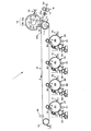
図1は、本発明にかかる画像形成装置の実施の形態の一例の一部を模式的にかつ部分的に示す図である。
この例の画像形成装置1は、固形分トナーとキャリアー液とを含む液体現像剤を用いて画像形成を行う。図1に示すように、画像形成装置1は、水平またはほぼ水平にタンデムに配置されたイエロー(Y)、マゼンタ(M)、シアン(C)およびブラック(K)の潜像担持体である感光体2Y,2M,2C,2Kを備えている。ここで、各感光体2Y,2M,
2C,2Kにおいて、2Yはイエローの感光体、2Mはマゼンタの感光体、2Cはシアン
の感光体、2Kはブラックの感光体を表す。また、他の部材についても同じように、部材の符号にそれぞれ各色のY,M,C,Kを添えて各色の部材を表す。
Hereinafter, embodiments for carrying out the present invention will be described with reference to the drawings.
FIG. 1 is a diagram schematically and partially showing a part of an embodiment of an image forming apparatus according to the present invention.
In this example, the image forming apparatus 1 forms an image using a liquid developer containing solid toner and a carrier liquid. As shown in FIG. 1, the image forming apparatus 1 is a photosensitive that is a latent image carrier of yellow (Y), magenta (M), cyan (C), and black (K) arranged in tandem horizontally or substantially horizontally. The
In 2C and 2K, 2Y represents a yellow photoreceptor, 2M represents a magenta photoreceptor, 2C represents a cyan photoreceptor, and 2K represents a black photoreceptor. Similarly, the members of the respective colors are represented by adding Y, M, C, and K of the respective colors to the reference numerals of the members.
各感光体2Y,2M,2C,2Kの周囲には、それぞれ、帯電部3Y,3M,3C,3Kが設けられている。また、各帯電部3Y,3M,3C,3Kから、それぞれ、各感光体2Y,2M,2C,2Kの回転方向αに向かって、順に、像書込部である露光部4Y,4M,4C,4K
、現像部5Y,5M,5C,5K、一次転写部6Y,6M,6C,6K、図示しない除電部、および感光体クリーニング部7Y,7M,7C,7Kが配設されている。
The developing
また、画像形成装置1は、転写ベルトであるとともに像担持体ベルトである無端状の中間転写ベルト8を備えている。この中間転写ベルト8は、各感光体2Y,2M,2C,2K
の上方に配置されている。そして、中間転写ベルト8は各一次転写部6Y,6M,6C,6
Kで各感光体2Y,2M,2C,2Kに圧接されている。
The image forming apparatus 1 also includes an endless
It is arranged above. The
K is pressed against each of the
図示しないが、中間転写ベルト8は、例えば樹脂等の可撓性の基材と、この基材の表面に形成されたゴム層等の弾性層と、この弾性層の表面に形成された表層とを有する3層構造の比較的柔らかい弾性ベルトに形成されている。もちろん、中間転写ベルト8はこれに限定されることはない。この中間転写ベルト8は図示しないモーターの駆動力が伝達される中間転写ベルト駆動ローラー9および中間転写ベルトテンションローラー10に張架されている。そして、図1に示すように中間転写ベルト8はテンションを付与された状態で、回転(移動)方向βに回転するようにされている。
なお、各色Y、M、C、Kに対応する感光体等の部材の配置順は、図1に示す例に限定されることはなく、任意に設定することができる。
Although not shown, the
Note that the arrangement order of members such as photoconductors corresponding to the respective colors Y, M, C, and K is not limited to the example shown in FIG. 1 and can be arbitrarily set.
中間転写ベルト8の中間転写ベルト駆動ローラー9側には転写装置である二次転写部11が設けられている。二次転写部11は、二次転写ローラー12および二次転写ローラークリーニング部13を備えている。
On the intermediate transfer
二次転写ローラー12は、その外周面に二次転写ローラー12の軸方向に延設された凹部14を有するとともに、凹部14を除く基材12aの円弧部の外周面に巻かれたゴムシート等のシート状の弾性部材12bを有している。その場合、図示しないが弾性部材12bの両端部は凹部14の側壁に固定されている。この弾性部材12bにより二次転写ローラー12の円弧部の外周面に抵抗層が形成されている。
The
また、二次転写ローラー12は、図示しないスプリング等の付勢手段の付勢力により弾性部材12bが中間転写ベルト8に圧接される。これにより、図1に示すように中間転写ベルト8と二次転写ローラー12の弾性部材12bとの間に二次転写ニップ11aが形成される。このとき、中間転写ベルト駆動ローラー9は二次転写ローラー12の押圧に対するバックアップローラーとして機能する。
Further, in the
更に、二次転写ローラー12には転写バイアスが印加される。そして、二次転写ローラー12は、中間転写ベルト8の移動方向βの移動時に回転方向γに回転するとともに転写バイアスが印加されることにより、二次転写ニップ11aで、中間転写ベルト8に転写されたトナー像を転写紙等の転写材に転写する。
Further, a transfer bias is applied to the
凹部14内には、転写材把持部材であるグリッパー15、グリッパー15が着座する転写材把持部材受け部材であるグリッパー支持部16、および転写材剥離部材である突き出し爪17が配設されている。図示しないが、グリッパー15は二次転写ローラー12の軸方向に沿って所定数配設されており、各グリッパー15は櫛歯状に構成されている。また、グリッパー支持部16は各グリッパー15に対応して配設されるとともに、突き出し爪17はグリッパー15の櫛歯の間および両端に位置する櫛歯の外側に配設されている。
In the
画像形成装置1は、転写材を二次転写ニップ11aの方へ給送するゲートローラー18(転写材送給部に相当)および転写材をガイドする転写材供給ガイド19を有する。中間転写ベルト8に担持されたトナー像が二次転写される際に、ゲートローラー18は転写材を二次転写ニップ11aの方へ供給する。
The image forming apparatus 1 includes a gate roller 18 (corresponding to a transfer material feeding unit) that feeds a transfer material toward the secondary transfer nip 11a, and a transfer
そして、凹部14が二次転写ニップ11aに到達する直前に、グリッパー15はグリッパー支持部16に向かって回動してゲートローラー18から給送方向δに給送されてくる転写材20の先端部20aをグリッパー支持部16との間に把持する。また、グリッパー15は、二次転写ニップ11aを通過した後、グリッパー支持部16から離間する方向に回動して転写材20の先端部20aの把持を解放する。更に、グリッパー15による転写材把持の解放に相前後して、各突き出し爪17が突き出し位置に突き出される。これにより、転写材20の先端部の背面(転写材のトナー像の転写面と反対側の面)が各突き出し爪17から突き出される。こうして、転写材20が二次転写ローラー12から剥離される。その後、各突き出し爪17は凹部14内に戻る。これらのグリッパー15および突き出し爪17の各作動は、それぞれ二次転写ローラー12が回転することで図示しないグリッパー制御カムおよび突き出し爪制御カムによって制御される。
Then, immediately before the
図2(a)および(b)に示すように、中間転写ベルト駆動ローラー9および二次転写ローラー12は、同一の中間転写ベルト・二次転写ローラー駆動モーター21によって回転駆動される。すなわち、中間転写ベルト・二次転写ローラー駆動モーター21の駆動力が、中間転写ベルト・二次転写ローラー駆動モーター21の回転軸に一体回転可能に取り付けられたモーターギア22および中間転写ベルト駆動ローラー9の回転軸9aに一体回転可能に取り付けられた中間転写ベルト駆動ローラー駆動ギア23を介して中間転写ベルト駆動ローラー9に伝達される。これにより、中間転写ベルト駆動ローラー9が図2(a)において矢印で示す反時計回りに回転する。また、中間転写ベルト・二次転写ローラー駆動モーター21の駆動力が、モーターギア22、中間ギア24、および二次転写ローラー12の回転軸12cに一体回転可能に取り付けられた二次転写ローラー駆動ギア25を介して二次転写ローラー12に伝達される。これにより、二次転写ローラー12が図2(a)において矢印で示す時計回りに回転する。
As shown in FIGS. 2A and 2B, the intermediate transfer
図1に示すように、二次転写ローラー12の一端側には、二次転写ローラー12の回転位置を検出する二次転写ローラー位置検出器(転写ローラー位置検出部に相当)であるエンコーダー26およびコードホイール27がこのエンコーダー26に隣接して設けられている。コードホイール27はスリット(切欠)27aを有する円板から構成され、二次転写ローラー12の回転軸(不図示)に二次転写ローラー12と一体回転するように設けられている。これらのエンコーダー26およびコードホイール27は従来公知のものを用いることができる。そして、エンコーダー26はコードホイール27のスリット27aの回
転位置を検出して二次転写ローラー12の二次転写ローラー位置信号を出力する。すなわち、二次転写ローラー12の回転位置が検出される。その場合、凹部14は二次転写ローラー12に一体に設けられることから、二次転写ローラー12の回転位置と凹部14の回転位置とは相対的に変化することはなく、両回転位置は一義的に決まる。したがって、エンコーダー26が出力する二次転写ローラー位置信号は凹部14の凹部位置信号であり、これらのエンコーダー26およびコードホイール27は凹部14の回転位置を検出する凹部位置検出器となっている。
As shown in FIG. 1, on one end side of the
また、中間転写ベルト8の回転(移動)位置を検出する中間転写ベルト位置検出器28(ベルト位置検出部に相当)が、中間転写ベルトテンションローラー10の近傍に配設されている。この中間転写ベルト位置検出器28は、例えば公知の光反射型センサーあるい光透過型センサー等の図示しない光学センサーと、図3(a)および(b)に示すように中間転写ベルト8の一側縁に中間転写ベルト8の移動方向βに等ピッチの間隔を置いて、あるいは中間転写ベルト8の一側縁の所定位置に中間転写ベルト8と一体にこの中間転写ベルト8の移動方向βと直交またはほぼ直交する方向に突設された所定数の中間転写ベルト位置検出マーク28aとを有している。なお、中間転写ベルト位置検出マーク28aは、図3(a)および(b)に示す例以外に、中間転写ベルト8の像担持領域(一次転写領域)外の領域に、中間転写ベルト8の移動位置を検出可能であれば他の中間転写ベルト位置検出マークで構成することもできる。そして、中間転写ベルト8の移動時に光学センサーがこれらの中間転写ベルト位置検出マーク28aを検出し、中間転写ベルト位置検出器28は、光学センサーが検出した中間転写ベルト位置検出マークに基づいて中間転写ベルト8の中間転写ベルト位置信号を出力する。すなわち、中間転写ベルト位置検出器28により、中間転写ベルト8の位置が検出される。
Further, an intermediate transfer belt position detector 28 (corresponding to a belt position detection unit) that detects the rotation (movement) position of the
図4は、中間転写ベルト・二次転写ローラー駆動モーターおよびゲートローラー駆動モーターの制御のブロック図である。
図4に示すように、中間転写ベルト・二次転写ローラー駆動モーター21は画像形成装置1の電子制御部(制御部)29で制御される。また、ゲートローラー18を駆動するゲートローラー駆動モーター30も制御部29で制御される。その場合、制御部29は、エンコーダー26からの二次転写ローラー位置信号および中間転写ベルト位置検出器28からの中間転写ベルト位置信号に基づいて、ゲートローラー駆動モーター30を駆動制御する。これにより、転写材20が二次転写ローラー12の凹部14以外の転写画像領域に確実に位置するようにされる。したがって、転写が行われない凹部14の領域に転写材20が位置することにより生じる転写不良が防止される。
FIG. 4 is a block diagram of control of the intermediate transfer belt / secondary transfer roller driving motor and the gate roller driving motor.
As shown in FIG. 4, the intermediate transfer belt / secondary transfer
次に、本実施形態における中間転写ベルト8の回転位置および二次転写ローラー12の凹部14の回転位置に基づいて、ゲートローラー18の回転のシーケンス制御について説明する。この例の画像形成装置1では、基本的に二次転写ローラー12の凹部14の回転位置に基づいて、ゲートローラー18による転写材20の送給タイミングを制御している。
Next, based on the rotation position of the
図5は、この例の画像形成装置1における転写材20の送給タイミングの基本的なシーケンス制御である第1実施例を示す図である。制御部29は画像形成指令信号により、中間転写ベルト・二次転写ローラー駆動モーター21を回転駆動する。そして、図5に示すように制御部29は、エンコーダー26からの1回目の凹部位置信号(ON信号)が供給されると、この凹部位置信号(ON信号)に基づいて、凹部14が二次転写ローラー12の回転方向γで二次転写ニップ11aに到達する直前に来たとき、1枚目の転写材20の先端部20aがこの凹部14に到達するタイミングでゲートローラー駆動モーター30にゲートローラー信号(ON信号)を出力する。すると、ゲートローラー駆動モーター30が回転駆動する。これにより、1枚目の転写材20の送給のためにゲートローラー18が
回転される。
FIG. 5 is a diagram showing a first embodiment which is basic sequence control of the feeding timing of the
次に、制御部29は、エンコーダー26からの次の2回目の凹部位置信号(ON信号)が供給された後においてゲートローラー18の回転開始から所定時間経過後、つまりゲートローラー18の回転が所定回転量になると、ゲートローラー信号(ON信号)の出力を停止する(ゲートローラー信号:OFF)。すると、1枚目の転写材20の送給のためのゲートローラー18の回転が停止する。このときには、1枚目の転写材20はグリッパー15によって確実に把持されて二次転写ローラー12の凹部以外の転写画像領域の外周面にガイドされて二次転写ニップ11aの方へ搬送される。2回目の凹部位置信号(ON信号)が供給された後、前述の1回目の凹部位置信号(ON信号)の場合と同様のタイミングで、ゲートローラー18が回転され、2枚目の転写材20の送給が行われる。更に、制御部29はエンコーダー26からの3回目の凹部位置信号(ON信号)が供給されると、前述と同様にしてゲートローラー18の回転を制御する。そして、制御部29はエンコーダー26からの次の凹部位置信号(ON信号)が供給されない場合には、直前のゲートローラー18の回転が所定回転量になった後、ゲートローラー18の回転を停止するとともにゲートローラー18の回転停止から所定時間経過後に中間転写ベルト・二次転写ローラー駆動モーター21を回転を停止する。これにより、画像形成装置1の画像形成作動が終了する。
Next, after the next second recess position signal (ON signal) is supplied from the
この第1実施例における転写材20の送給のシーケンス制御時は、中間転写ベルト位置検出器28からの中間転写ベルト位置信号(ON信号)に対して常に一定の関係(一定のタイミング)で、例えば中間転写ベルト位置信号(ON信号)の出力後の一定時間経過後に、エンコーダー26からの凹部位置信号(ON信号)が制御部29に供給される。したがって、中間転写ベルト位置信号(ON信号)に基づいた凹部位置信号(ON信号)が制御部29に供給される。そして、制御部29はこの凹部位置信号(ON信号)に基づいてゲートローラー駆動モーター30へゲートローラー信号(ON信号)を出力する。これにより、ゲートローラー18は転写材20を給送開始する。したがって、転写材20の画像形成可能領域が二次転写ローラー12の凹部14以外の転写画像領域に確実に位置するとともに、中間転写ベルト8に一次転写されたトナー像が二次転写時に転写材20の画像形成可能領域に確実に位置するようになる。その結果、転写が行われない凹部14の領域に転写材20が位置することおよび中間転写ベルト8のトナー像が転写材20の画像形成可能領域外に位置することにより生じる転写不良が防止される。
During the transfer sequence control of the
この例の画像形成装置1では、給送されてきた転写材20の先端部20aがグリッパー15で把持された状態で二次転写が行われる。そして、グリッパー15による転写材把持部が二次転写ニップ11aを通過すると、グリッパー15による転写材20の把持が解放されるとともに、転写材20は二次転写ローラー12から剥離するようになるが、このとき突き出し爪17により突き出されて二次転写ローラー12からより確実に剥離される。図示しないが、二次転写ローラー12から剥離した転写材20は従来の画像形成装置と同様に定着部に搬送されて転写材のトナー像が定着された後、排転写材トレイに排出される。
In the image forming apparatus 1 of this example, the secondary transfer is performed in a state where the
この第1実施例の画像形成装置1によれば、二次転写ローラー12に形成された凹部14の位置が中間転写ベルト8の移動(回転)位置に基づいて制御されるとともに、制御された凹部14の位置に基づいて、ゲートローラー18からの転写材20の供給開始のタイミングが制御される。したがって、凹部14の位置に対して転写材33の位置を制御可能となり、凹部14が二次転写ニップ11aの位置に来た時は、転写材20が二次転写ニップ11aの位置、つまり凹部14に給送されないようにすることができる。これにより、転写材20に対するトナー像の転写ずれの発生を抑制することができる。その結果、中間転写ベルト8に転写されたトナー像を転写材20の所定位置に高精度に転写することが可
能となる。
According to the image forming apparatus 1 of the first embodiment, the position of the
図6は、この例の画像形成装置1において二次転写ローラー12の凹部14の回転位置信号(ON信号)にずれを生じた場合のゲートローラー18による転写材20の送給のシーケンス制御である第2実施例を示す図である。この図6に示す第2実施例は、例えば二次転写ローラー12の仮想周長(凹部14がないものとしたときの二次転写ローラー12の周長)が300mmに対して中間転写ベルト8の周長が600mmであり、この中間転写ベルト8に300mm間隔で中間転写ベルト位置検出マーク28aが形成されているときの例である。このとき、中間転写ベルト8の周長が二次転写ローラー12の仮想周長の整数倍(2倍)であるため、中間転写ベルト位置信号が凹部位置信号と同期する。なお、これらの周長および中間転写ベルト位置検出マーク28aの配設位置は、前述の第1実施例でも同様である。
FIG. 6 is a sequence control of feeding the
図6に示すように、この第2実施例の転写材20の送給のシーケンス制御では、基本的には前述の第1実施例のシーケンス制御が行われる。ところで、二次転写ローラー12の凹部14が二次転写ニップ11a位置を通過する時の速度変化等により、エンコーダー26からの二次転写ローラー12の凹部位置信号(ON信号)の出力タイミングに、通常時の出力タイミングに対してずれを生じる場合が考えられる。このように凹部位置信号(ON信号)の出力タイミングにずれが生じると、第1実施例における通常時(ずれが発生していない時)の出力タイミングでゲートローラー信号(ON信号)が出力されると、転写材20が二次転写ローラー12の所定位置に給送されず、中間転写ベルト8のトナー像が転写材20の正規の位置に転写されなくなる。
As shown in FIG. 6, in the sequence control for feeding the
そこで、この第2実施例では、前述の第1実施例のシーケンス制御の実行中に、制御部29がエンコーダー26からの凹部位置信号(ON信号)と中間転写ベルト位置検出器28からの中間転写ベルト位置信号(ON信号)とを常時対比する。そして、制御部29は、凹部位置信号(ON信号)が中間転写ベルト位置信号(ON信号)に対して前述の一定の関係で供給されず、両信号の一定の関係の間に時間(出力タイミング)のずれを生じたか否かを判断する。制御部29は、例えば転写材の送給のある枚数のとき、凹部位置信号(ON信号)のタイミングが中間転写ベルト位置信号(ON信号)のタイミングに対してずれを生じたと判断すると、このずれに基づいてゲートローラー信号(ON信号)の出力タイミングを制御する。
Therefore, in the second embodiment, the
例えば、図6において凹部位置信号(ON信号)が中間転写ベルト位置信号(ON信号)の出力より前に出力され、両信号の一定の関係の間に出力タイミングのずれt1を生じ
たとする。このとき、凹部位置信号(ON信号)の出力タイミングが中間転写ベルト位置信号(ON信号)の出力タイミングより早いため、中間転写ベルト位置信号(ON信号)に関係なく転写材送給を行って二次転写を行うと、転写材20の先端部20aの余白幅が大きくなってしまう。
For example, in FIG. 6, it is assumed that the recess position signal (ON signal) is output before the output of the intermediate transfer belt position signal (ON signal), and an output timing shift t 1 occurs between the two signals in a certain relationship. At this time, since the output timing of the recess position signal (ON signal) is earlier than the output timing of the intermediate transfer belt position signal (ON signal), the transfer material is fed regardless of the intermediate transfer belt position signal (ON signal). When the next transfer is performed, the margin width of the
そこで、このずれt1が予め設定された基準量t0以上であるときは、制御部29は、凹部位置信号(ON信号)の出力タイミングに基準量t0以上のずれt1が発生したと判断してゲートローラー信号(ON信号)の出力タイミングを遅らせる。すなわち、制御部29は、ゲートローラー信号(ON信号)の出力タイミングを、基本的なシーケンス制御における凹部位置信号(ON信号)に基づく図6に二点鎖線で示す出力タイミングより時間t2だけ遅らせた図6に実線で示す出力タイミングに制御する。その場合、時間t2は、0より大きいとともにずれt1以下でずれt1に対応して設定される(0<t2≦t1)。このようにして、ゲートローラー信号(ON信号)の出力タイミングが凹部位置信号(ON信号)の出力タイミングのずれt1に基づいて調整(補正)され、調整(補正)されたゲート
ローラー信号(ON信号)の出力タイミングでゲートローラー18による転写材20の転
写材の送給開始タイミングが制御される。これにより、凹部位置信号(ON信号)の出力タイミングに基準量t0以上のずれt1が発生しても、転写材20の先端位置に対する画像転写位置を制御することが可能となる。その結果、中間転写ベルト8のトナー像が転写材20の所定位置により高精度に二次転写されるとともに、転写材20の先端部20aの余白幅の増大が抑制される。
Therefore, when the deviation t 1 is greater than or equal to the preset reference amount t 0 , the
また、凹部位置信号(ON信号)が中間転写ベルト位置信号(ON信号)の出力から一定の関係より遅く出力され、基準量t0以上の出力タイミングのずれt1′を生じたとする。この場合には、制御部29は、ゲートローラー信号(ON信号)の出力タイミングを、通常時の出力タイミングより早めた出力タイミングに制御する。
この第2実施例の他の構成は、第1実施例と同様である。
Further, it is assumed that the concave portion position signal (ON signal) is output later than a certain relationship from the output of the intermediate transfer belt position signal (ON signal), resulting in an output timing shift t 1 ′ greater than the reference amount t 0 . In this case, the
Other configurations of the second embodiment are the same as those of the first embodiment.
この第2実施例によれば、凹部14の回転位置に基づいて転写材20の供給を制御するにあたって、凹部14の位置が中間転写ベルト8の移動(回転)位置と常時対比している。そして、凹部14の位置が中間転写ベルト8の移動(回転)位置に対してずれたときは、凹部14の位置を基準とした転写材20の供給開始のタイミングをこの位置ずれを補正して制御している。その場合、この位置ずれの影響により生じる、転写材に対するトナー像の転写ずれが抑制されるように、ゲートローラー18の給送開始タイミングが調整(補正)される。これにより、凹部14の位置に位置ずれが生じても、転写材20の先端位置に対する画像転写位置をより高精度に制御することが可能となる。その結果、中間転写ベルト8に転写されたトナー像を転写材20の所定位置に高精度に転写することができる。
この第2実施例の他の作用効果は、第1実施例と同様である。
According to the second embodiment, when the supply of the
Other functions and effects of the second embodiment are the same as those of the first embodiment.
次に、本発明の画像形成装置の実施の形態の他の例である第3実施例について説明する。
図7は、第3実施例における中間転写ベルト・二次転写ローラー駆動モーターおよび露光部の制御のブロック図である。
Next, a third example which is another example of the embodiment of the image forming apparatus of the present invention will be described.
FIG. 7 is a block diagram of control of the intermediate transfer belt / secondary transfer roller drive motor and the exposure unit in the third embodiment.
この第3実施例の画像形成装置1では、中間転写ベルト位置信号(ON信号)に基づいて、露光部4Y,4M,4C,4Kの露光開始タイミング(像書込み開始タイミング)を制
御している。すなわち、図7に示すように第3例の制御部29には、第1および第2実施例とは異なり露光部4Y,4M,4C,4Kが接続されるとともにゲートローラー駆動モー
ター30は接続されない。
In the image forming apparatus 1 of the third embodiment, the exposure start timing (image writing start timing) of the
図8は、この例の画像形成装置1において中間転写ベルト8の位置信号(ON信号)にずれを生じた場合の各露光部4Y,4M,4C,4Kによる像の書込みのシーケンス制御で
ある第3実施例を示す図である。この図8に示す第3実施例は、例えば二次転写ローラー12の仮想周長が600mmに対して中間転写ベルト8の周長が900mmであり、この中間転写ベルト8に300mm間隔で中間転写ベルト位置検出マーク28aが形成されているときの例である。この例では、中間転写ベルト8の周長が二次転写ローラー12の仮想周長の整数倍ではないが、両者の周長が互いに同じ公約数を有する関係にあるため、第1および第2実施例と同様に中間転写ベルト位置信号が凹部位置信号と同期する。
FIG. 8 is a sequence control of image writing by the
図8に示すようにこの第3実施例の画像形成装置1では、中間転写ベルト位置信号に基づいて露光部4Y,4M,4C,4Kの露光開始タイミングのシーケンス制御が実行される
。すなわち、制御部29は画像形成指令信号により、中間転写ベルト・二次転写ローラー駆動モーター21を回転駆動する。そして、図6に示すように制御部29は、中間転写ベルト位置検出器28からの1回目の中間転写ベルト位置信号(ON信号)が供給されると、この中間転写ベルト位置信号(ON信号)に基づいて、中間転写ベルト8の所定位置に各感光体2Y,2M,2C,2Kの各トナー像が一次転写されるタイミングで各露光部4Y,
4M,4C,4Kにそれぞれ露光開始信号(ON信号)を出力する。すると、各露光部4Y,4M,4C,4Kはそれぞれ各露光開始信号(ON信号)により、1回目の各感光体2Y,2M,2C,2Kに対して露光を開始し、各感光体2Y,2M,2C,2Kがそれぞれ書き込
む潜像応じて所定時間露光される。そして、制御部29は2回目以降の露光について、露光開始信号(ON信号)を所定(図8に示す例では1つおき)の中間転写ベルト位置信号(ON信号)に基づいて同様に出力する。
As shown in FIG. 8, in the image forming apparatus 1 of the third embodiment, sequence control of the exposure start timing of the
Exposure start signals (ON signals) are output to 4M, 4C, and 4K, respectively. Then, each of the
この第3実施例における露光開始のシーケンス制御時は、エンコーダー26からの凹部位置信号(ON信号)に対して常に一定の関係(一定のタイミング)で、例えば凹部位置信号(ON信号)の出力後の一定時間経過後に、中間転写ベルト位置検出器28からの中間転写ベルト位置信号(ON信号)が制御部29に供給される。したがって、凹部位置信号(ON信号)に基づいた中間転写ベルト位置信号(ON信号)が制御部29に供給される。そして、制御部29はこの中間転写ベルト位置信号(ON信号)に基づいて各露光部4Y,4M,4C,4Kへそれぞれ露光開始信号(ON信号)を出力する。これにより、各
露光部4Y,4M,4C,4Kはそれぞれ対応する感光体2Y,2M,2C,2Kに対して露光を開始し、各感光体2Y,2M,2C,2Kにそれぞれ潜像が書き込まれる。したがって、
転写が行われない二次転写ローラー12の凹部14の領域外に中間転写ベルト8のトナー像が確実に位置するようになる。その結果、中間転写ベルト8に一次転写されたトナー像が転写材20に確実に二次転写され、転写不良が防止される。
In the sequence control of the exposure start in the third embodiment, it is always in a constant relation (constant timing) with respect to the concave position signal (ON signal) from the
As a result, the toner image on the
ところで、中間転写ベルト8の伸び縮みや中間転写ベルト駆動ローラー9に対する中間転写ベルト8のすべり等により、中間転写ベルト位置検出器28からの中間転写ベルト位置信号(ON信号)の出力タイミングにずれが生じる場合が考えられる。そこで、この第3実施例では、前述の露光開始のシーケンス制御の実行中に、制御部29が中間転写ベルト位置信号(ON信号)の出力タイミングと凹部位置信号(ON信号)の出力タイミングとを常時対比する。そして、制御部29は、中間転写ベルト位置信号(ON信号)の出力タイミングが凹部位置信号(ON信号)の出力タイミングに対して前述の一定の関係で供給されず、両信号の出力タイミングの一定の関係の間にずれを生じたか否かを判断する。制御部29は、例えばある露光回数のとき、中間転写ベルト位置信号(ON信号)のタイミングが凹部位置信号(ON信号)のタイミングに対してずれを生じたとすると、このずれに基づいて各露光部4Y,4M,4C,4Kの各露光開始信号の出力タイミングを制御す
る。
By the way, the output timing of the intermediate transfer belt position signal (ON signal) from the intermediate transfer
例えば、図8において中間転写ベルト位置信号(ON信号)の出力が凹部位置信号(ON信号)より前に出力され、両信号の一定の関係の間に出力タイミングのずれt3を生じ
たとする。このずれt3が予め設定された基準量t0′以上であると、制御部29は、中間転写ベルト位置信号(ON信号)の出力タイミングに基準量t0′以上のずれt3が発生したと判断して露光開始信号(ON信号)の出力タイミングを遅らせる。すなわち、制御部29は、露光開始信号(ON信号)の出力タイミングを、通常時(ずれを生じない時)のシーケンス制御における中間転写ベルト位置信号(ON信号)に基づく図8に二点鎖線で示す出力タイミングより時間t4だけ遅らせた図8に実線で示す出力タイミングに制御す
る。その場合、時間t4は、0より大きいとともにずれt3以下でずれt3に対応して設定
される(0<t4≦t3)。このようにして、各露光開始信号(ON信号)の出力タイミングが中間転写ベルト位置信号(ON信号)の出力タイミングのずれt3に基づいて調整(
補正)され、調整(補正)された露光開始信号(ON信号)の出力タイミングで各露光開始が制御される。
For example, in FIG. 8, it is assumed that the output of the intermediate transfer belt position signal (ON signal) is output before the recess position signal (ON signal), and an output timing shift t 3 occurs between the two signals in a certain relationship. If the deviation t 3 is greater than or equal to a preset reference amount t 0 ′, the
Each exposure start is controlled at the output timing of the exposure start signal (ON signal) that has been corrected and adjusted (corrected).
また、中間転写ベルト位置信号(ON信号)が凹部位置信号(ON信号)の出力から一定の関係より遅く出力され、基準量t0′以上の出力タイミングのずれt3′を生じたとする。この場合には、制御部29は、露光開始信号(ON信号)の出力タイミングを、通常
時の出力タイミングより早めた出力タイミングに制御する。
Further, it is assumed that the intermediate transfer belt position signal (ON signal) is output later than a certain relationship from the output of the recess position signal (ON signal), and an output timing shift t 3 ′ greater than the reference amount t 0 ′ occurs. In this case, the
この第3実施例の画像形成装置1によれば、中間転写ベルト8の移動(回転)位置が二次転写ローラー12に形成された凹部14の位置に基づいて制御されるとともに、制御された中間転写ベルト8の位置に基づいて、各露光装置4Y,4M,4C,4Kの露光開始の
タイミングがそれぞれ制御される。したがって、中間転写ベルト8の所定位置に転写されるように、各露光装置4Y,4M,4C,4Kによる各感光体2Y,2M,2C,2Kの露光開始(つまり、各感光体2Y,2M,2C,2Kへの像書込開始)のタイミングを制御するこ
とが可能となる。これにより、各色のトナー像の色ずれの発生を抑制することができる。そして、中間転写ベルト8の位置が二次転写ローラー12の凹部14の回転位置に基づいて制御されることで、中間転写ベルト8に色ずれが抑制されて転写されたトナー像を転写材20の所定位置に高精度に転写することが可能となる。
According to the image forming apparatus 1 of the third embodiment, the movement (rotation) position of the
また、中間転写ベルト8の位置に基づいて各露光装置4Y,4M,4C,4Kによる露光
開始のタイミングを制御するにあたって、中間転写ベルト8の移動位置が凹部14の位置と常時対比されている。そして、中間転写ベルト8の位置が凹部14の位置に対してずれたときは、中間転写ベルト8の位置を基準とした各露光装置4Y,4M,4C,4Kによる
露光開始のタイミングを、この位置ずれを補正して制御している。その場合、この位置ずれの影響により生じる、転写材に対するトナー像の転写ずれが抑制されるように、各露光装置4Y,4M,4C,4Kによる露光開始のタイミングが調整される。これにより、中間
転写ベルト8の位置に位置ずれが生じても、転写材20の先端位置に対する画像転写位置をより高精度に制御することが可能となる。その結果、中間転写ベルト8に転写されたトナー像を転写材20の所定位置に高精度に転写することが可能となる。
この第3実施例の他の構成および他の作用効果は、第2実施例と同様である。
Further, when the exposure start timing by the
Other configurations and other functions and effects of the third embodiment are the same as those of the second embodiment.
なお、本発明の画像形成装置および画像形成方法は、前述の実施の形態の各例に限定されることはない。例えば、前述の例では、像担持体として中間転写ベルト8を用いているが、中間転写ドラムを用いることもできるし、像担持体として感光体とすることもできる。像担持体に感光体を用いる場合は、感光体のトナー像が転写材に直接転写されることになる。また、前述の各例の画像形成装置では、タンデム型の画像形成装置としているが、他の形式の画像形成装置でもよいし、単色の画像形成装置でもよい。要は、本発明は特許請求の範囲に記載されている事項の範囲内で種々の設計変更が可能である。
The image forming apparatus and the image forming method of the present invention are not limited to the examples of the above-described embodiments. For example, in the above-described example, the
1…画像形成装置、2Y,2M,2C,2K…感光体、5Y,5M,5C,5K…現像部、6Y,6M,6C,6K…一次転写部、8…中間転写ベルト、9…ベルト駆動ローラー、11…
二次転写部、11a…二次転写ニップ、12…二次転写ローラー、14…凹部、18…ゲートローラー、20…転写材、21…中間転写ベルト・二次転写ローラー駆動モーター、26…エンコーダー、27…コードホイール、28…中間転写ベルト位置検出器、28a…中間転写ベルト位置検出マーク、29…電子制御部(制御部)、30…ゲートローラー駆動モーター
DESCRIPTION OF SYMBOLS 1 ... Image forming apparatus, 2Y, 2M, 2C, 2K ... Photoconductor, 5Y, 5M, 5C, 5K ... Developing part, 6Y, 6M, 6C, 6K ... Primary transfer part, 8 ... Intermediate transfer belt, 9 ... Belt drive Roller, 11 ...
Secondary transfer section, 11a ... secondary transfer nip, 12 ... secondary transfer roller, 14 ... concave, 18 ... gate roller, 20 ... transfer material, 21 ... intermediate transfer belt / secondary transfer roller drive motor, 26 ... encoder, DESCRIPTION OF
Claims (7)
周面に凹部を有するとともに、前記像担持体ベルトに転写材を圧接して転写ニップを形成し、前記転写ニップで前記像担持体ベルトに担持された前記像を前記転写材に転写する転写ローラーと、
前記像担持体ベルトの位置を検出するベルト位置検出部と、
前記転写ローラーの回転位置を検出する転写ローラー位置検出部と、
を有することを特徴とする画像形成装置。 An image carrier belt carrying an image;
A transfer roller having a recess on the peripheral surface, forming a transfer nip by pressing a transfer material against the image carrier belt, and transferring the image carried on the image carrier belt to the transfer material at the transfer nip When,
A belt position detector for detecting the position of the image carrier belt;
A transfer roller position detector for detecting the rotation position of the transfer roller;
An image forming apparatus comprising:
前記転写ローラー位置検出部で検出された前記転写ローラーの回転位置に基づいて前記転写材給送部の前記転写材の給送を制御する制御部と、
を有する請求項1に記載の画像形成装置。 A transfer material feeding section for feeding the transfer material to the transfer nip;
A control unit that controls feeding of the transfer material of the transfer material feeding unit based on the rotational position of the transfer roller detected by the transfer roller position detection unit;
The image forming apparatus according to claim 1, comprising:
前記像書込部で潜像が書き込まれる潜像担持体と、
前記潜像担持体に書き込まれた前記潜像を現像する現像部と、
前記現像部で現像された像を前記像担持体ベルトに転写する転写部と、
前記ベルト位置検出部で検出された前記像担持体ベルトの位置に基づいて前記像書込部の像書込みを制御する制御部と、
を有する請求項1に記載の画像形成装置。 An image writing unit for writing a latent image;
A latent image carrier on which a latent image is written by the image writing unit;
A developing unit for developing the latent image written on the latent image carrier;
A transfer unit that transfers the image developed by the developing unit to the image carrier belt;
A control unit for controlling image writing of the image writing unit based on the position of the image carrier belt detected by the belt position detection unit;
The image forming apparatus according to claim 1, comprising:
検出された前記転写ローラーの回転位置に基づいて制御して転写材を前記転写ニップに給送し、
給送された前記転写材へ前記像担持体ベルトに担持された像を転写することを特徴とする画像形成方法。 Detecting the rotational position of the transfer roller that forms a transfer nip with the image carrier belt and has a recess,
Control based on the detected rotational position of the transfer roller to feed the transfer material to the transfer nip,
An image forming method, wherein the image carried on the image carrier belt is transferred to the fed transfer material.
検出された前記像担持体ベルトの位置と検出された前記転写ローラーの回転位置とに基づいて、前記転写材を前記転写ニップに給送するタイミングを制御により調整する請求項6に記載の画像形成方法。 Detect the position of the image carrier belt that carries the image,
The image formation according to claim 6, wherein the timing for feeding the transfer material to the transfer nip is adjusted by control based on the detected position of the image carrier belt and the detected rotational position of the transfer roller. Method.
Priority Applications (1)
| Application Number | Priority Date | Filing Date | Title |
|---|---|---|---|
| JP2009143946A JP2011002532A (en) | 2009-06-17 | 2009-06-17 | Image forming apparatus and image forming method |
Applications Claiming Priority (1)
| Application Number | Priority Date | Filing Date | Title |
|---|---|---|---|
| JP2009143946A JP2011002532A (en) | 2009-06-17 | 2009-06-17 | Image forming apparatus and image forming method |
Publications (1)
| Publication Number | Publication Date |
|---|---|
| JP2011002532A true JP2011002532A (en) | 2011-01-06 |
Family
ID=43560550
Family Applications (1)
| Application Number | Title | Priority Date | Filing Date |
|---|---|---|---|
| JP2009143946A Pending JP2011002532A (en) | 2009-06-17 | 2009-06-17 | Image forming apparatus and image forming method |
Country Status (1)
| Country | Link |
|---|---|
| JP (1) | JP2011002532A (en) |
Cited By (32)
| Publication number | Priority date | Publication date | Assignee | Title |
|---|---|---|---|---|
| CN104220935A (en) * | 2012-03-05 | 2014-12-17 | 兰达公司 | Control apparatus and method for digital printing system |
| US9884479B2 (en) | 2012-03-05 | 2018-02-06 | Landa Corporation Ltd. | Apparatus and method for control or monitoring a printing system |
| US10357985B2 (en) | 2012-03-05 | 2019-07-23 | Landa Corporation Ltd. | Printing system |
| US10357963B2 (en) | 2012-03-05 | 2019-07-23 | Landa Corporation Ltd. | Digital printing process |
| US10427399B2 (en) | 2015-04-14 | 2019-10-01 | Landa Corporation Ltd. | Apparatus for threading an intermediate transfer member of a printing system |
| US10434761B2 (en) | 2012-03-05 | 2019-10-08 | Landa Corporation Ltd. | Digital printing process |
| US10477188B2 (en) | 2016-02-18 | 2019-11-12 | Landa Corporation Ltd. | System and method for generating videos |
| US10569533B2 (en) | 2012-03-15 | 2020-02-25 | Landa Corporation Ltd. | Endless flexible belt for a printing system |
| US10569532B2 (en) | 2012-03-05 | 2020-02-25 | Landa Corporation Ltd. | Digital printing system |
| US10569534B2 (en) | 2012-03-05 | 2020-02-25 | Landa Corporation Ltd. | Digital printing system |
| US10596804B2 (en) | 2015-03-20 | 2020-03-24 | Landa Corporation Ltd. | Indirect printing system |
| US10632740B2 (en) | 2010-04-23 | 2020-04-28 | Landa Corporation Ltd. | Digital printing process |
| US10642198B2 (en) | 2012-03-05 | 2020-05-05 | Landa Corporation Ltd. | Intermediate transfer members for use with indirect printing systems and protonatable intermediate transfer members for use with indirect printing systems |
| US10759953B2 (en) | 2013-09-11 | 2020-09-01 | Landa Corporation Ltd. | Ink formulations and film constructions thereof |
| US10800936B2 (en) | 2012-03-05 | 2020-10-13 | Landa Corporation Ltd. | Ink film constructions |
| US10889128B2 (en) | 2016-05-30 | 2021-01-12 | Landa Corporation Ltd. | Intermediate transfer member |
| US10926532B2 (en) | 2017-10-19 | 2021-02-23 | Landa Corporation Ltd. | Endless flexible belt for a printing system |
| US10933661B2 (en) | 2016-05-30 | 2021-03-02 | Landa Corporation Ltd. | Digital printing process |
| US10994528B1 (en) | 2018-08-02 | 2021-05-04 | Landa Corporation Ltd. | Digital printing system with flexible intermediate transfer member |
| US11267239B2 (en) | 2017-11-19 | 2022-03-08 | Landa Corporation Ltd. | Digital printing system |
| US11318734B2 (en) | 2018-10-08 | 2022-05-03 | Landa Corporation Ltd. | Friction reduction means for printing systems and method |
| US11321028B2 (en) | 2019-12-11 | 2022-05-03 | Landa Corporation Ltd. | Correcting registration errors in digital printing |
| US11465426B2 (en) | 2018-06-26 | 2022-10-11 | Landa Corporation Ltd. | Intermediate transfer member for a digital printing system |
| US11511536B2 (en) | 2017-11-27 | 2022-11-29 | Landa Corporation Ltd. | Calibration of runout error in a digital printing system |
| US11679615B2 (en) | 2017-12-07 | 2023-06-20 | Landa Corporation Ltd. | Digital printing process and method |
| US11707943B2 (en) | 2017-12-06 | 2023-07-25 | Landa Corporation Ltd. | Method and apparatus for digital printing |
| US11787170B2 (en) | 2018-12-24 | 2023-10-17 | Landa Corporation Ltd. | Digital printing system |
| US11833813B2 (en) | 2019-11-25 | 2023-12-05 | Landa Corporation Ltd. | Drying ink in digital printing using infrared radiation |
| US12001902B2 (en) | 2018-08-13 | 2024-06-04 | Landa Corporation Ltd. | Correcting distortions in digital printing by implanting dummy pixels in a digital image |
| US12011920B2 (en) | 2019-12-29 | 2024-06-18 | Landa Corporation Ltd. | Printing method and system |
| US12358277B2 (en) | 2019-03-31 | 2025-07-15 | Landa Corporation Ltd. | Systems and methods for preventing or minimizing printing defects in printing processes |
| US12430453B2 (en) | 2021-02-02 | 2025-09-30 | Landa Corporation Ltd. | Mitigating distortions in printed images |
-
2009
- 2009-06-17 JP JP2009143946A patent/JP2011002532A/en active Pending
Cited By (35)
| Publication number | Priority date | Publication date | Assignee | Title |
|---|---|---|---|---|
| US10632740B2 (en) | 2010-04-23 | 2020-04-28 | Landa Corporation Ltd. | Digital printing process |
| CN104220935A (en) * | 2012-03-05 | 2014-12-17 | 兰达公司 | Control apparatus and method for digital printing system |
| US10569532B2 (en) | 2012-03-05 | 2020-02-25 | Landa Corporation Ltd. | Digital printing system |
| CN109940988A (en) * | 2012-03-05 | 2019-06-28 | 兰达公司 | Control device and method for digital printing system |
| US10357985B2 (en) | 2012-03-05 | 2019-07-23 | Landa Corporation Ltd. | Printing system |
| US10357963B2 (en) | 2012-03-05 | 2019-07-23 | Landa Corporation Ltd. | Digital printing process |
| US10642198B2 (en) | 2012-03-05 | 2020-05-05 | Landa Corporation Ltd. | Intermediate transfer members for use with indirect printing systems and protonatable intermediate transfer members for use with indirect printing systems |
| US9884479B2 (en) | 2012-03-05 | 2018-02-06 | Landa Corporation Ltd. | Apparatus and method for control or monitoring a printing system |
| JP2015515394A (en) * | 2012-03-05 | 2015-05-28 | ランダ コーポレイション リミテッド | Control apparatus and method for digital printing system |
| US10518526B2 (en) | 2012-03-05 | 2019-12-31 | Landa Corporation Ltd. | Apparatus and method for control or monitoring a printing system |
| US10800936B2 (en) | 2012-03-05 | 2020-10-13 | Landa Corporation Ltd. | Ink film constructions |
| US10434761B2 (en) | 2012-03-05 | 2019-10-08 | Landa Corporation Ltd. | Digital printing process |
| US10569534B2 (en) | 2012-03-05 | 2020-02-25 | Landa Corporation Ltd. | Digital printing system |
| US10569533B2 (en) | 2012-03-15 | 2020-02-25 | Landa Corporation Ltd. | Endless flexible belt for a printing system |
| US10759953B2 (en) | 2013-09-11 | 2020-09-01 | Landa Corporation Ltd. | Ink formulations and film constructions thereof |
| US10596804B2 (en) | 2015-03-20 | 2020-03-24 | Landa Corporation Ltd. | Indirect printing system |
| US10427399B2 (en) | 2015-04-14 | 2019-10-01 | Landa Corporation Ltd. | Apparatus for threading an intermediate transfer member of a printing system |
| US10477188B2 (en) | 2016-02-18 | 2019-11-12 | Landa Corporation Ltd. | System and method for generating videos |
| US10933661B2 (en) | 2016-05-30 | 2021-03-02 | Landa Corporation Ltd. | Digital printing process |
| US10889128B2 (en) | 2016-05-30 | 2021-01-12 | Landa Corporation Ltd. | Intermediate transfer member |
| US10926532B2 (en) | 2017-10-19 | 2021-02-23 | Landa Corporation Ltd. | Endless flexible belt for a printing system |
| US11267239B2 (en) | 2017-11-19 | 2022-03-08 | Landa Corporation Ltd. | Digital printing system |
| US11511536B2 (en) | 2017-11-27 | 2022-11-29 | Landa Corporation Ltd. | Calibration of runout error in a digital printing system |
| US11707943B2 (en) | 2017-12-06 | 2023-07-25 | Landa Corporation Ltd. | Method and apparatus for digital printing |
| US11679615B2 (en) | 2017-12-07 | 2023-06-20 | Landa Corporation Ltd. | Digital printing process and method |
| US11465426B2 (en) | 2018-06-26 | 2022-10-11 | Landa Corporation Ltd. | Intermediate transfer member for a digital printing system |
| US10994528B1 (en) | 2018-08-02 | 2021-05-04 | Landa Corporation Ltd. | Digital printing system with flexible intermediate transfer member |
| US12001902B2 (en) | 2018-08-13 | 2024-06-04 | Landa Corporation Ltd. | Correcting distortions in digital printing by implanting dummy pixels in a digital image |
| US11318734B2 (en) | 2018-10-08 | 2022-05-03 | Landa Corporation Ltd. | Friction reduction means for printing systems and method |
| US11787170B2 (en) | 2018-12-24 | 2023-10-17 | Landa Corporation Ltd. | Digital printing system |
| US12358277B2 (en) | 2019-03-31 | 2025-07-15 | Landa Corporation Ltd. | Systems and methods for preventing or minimizing printing defects in printing processes |
| US11833813B2 (en) | 2019-11-25 | 2023-12-05 | Landa Corporation Ltd. | Drying ink in digital printing using infrared radiation |
| US11321028B2 (en) | 2019-12-11 | 2022-05-03 | Landa Corporation Ltd. | Correcting registration errors in digital printing |
| US12011920B2 (en) | 2019-12-29 | 2024-06-18 | Landa Corporation Ltd. | Printing method and system |
| US12430453B2 (en) | 2021-02-02 | 2025-09-30 | Landa Corporation Ltd. | Mitigating distortions in printed images |
Similar Documents
| Publication | Publication Date | Title |
|---|---|---|
| JP2011002532A (en) | Image forming apparatus and image forming method | |
| US8060003B2 (en) | Image forming apparatus wherein a setting unit sets an interval of image formation according to a size of a recording medium | |
| US7643781B2 (en) | Transfer device and image forming apparatus | |
| JP2006243212A (en) | Image forming apparatus | |
| CN101592896A (en) | Color image forming apparatus | |
| US8145108B2 (en) | Image forming apparatus | |
| JP2010249997A (en) | Image forming apparatus and image forming method | |
| JP2013020065A (en) | Image forming device | |
| JP2012088377A (en) | Image forming apparatus | |
| JP2011017765A (en) | Image forming apparatus and image forming method | |
| JP2011008058A (en) | Image forming apparatus and image forming method | |
| JP5188554B2 (en) | Color image forming apparatus | |
| JP2005121771A (en) | Image forming apparatus | |
| JP2005215482A (en) | Image forming apparatus | |
| JPH1172980A (en) | Image forming device | |
| JP2011008057A (en) | Image forming apparatus and image forming method | |
| JP3868318B2 (en) | Image forming apparatus | |
| JP4928285B2 (en) | Image forming apparatus | |
| JP4701915B2 (en) | Image forming apparatus | |
| JP2006201270A (en) | Image forming apparatus | |
| JP6041518B2 (en) | Image forming apparatus | |
| JP2004198624A (en) | Image forming device | |
| JP4476584B2 (en) | Image forming apparatus | |
| JP3733305B2 (en) | Image forming apparatus | |
| JP2009276582A (en) | Image forming apparatus |