JP2010525203A - Locking device - Google Patents
Locking device Download PDFInfo
- Publication number
- JP2010525203A JP2010525203A JP2010506127A JP2010506127A JP2010525203A JP 2010525203 A JP2010525203 A JP 2010525203A JP 2010506127 A JP2010506127 A JP 2010506127A JP 2010506127 A JP2010506127 A JP 2010506127A JP 2010525203 A JP2010525203 A JP 2010525203A
- Authority
- JP
- Japan
- Prior art keywords
- locking device
- cylinder core
- adapter
- end position
- extension
- Prior art date
- Legal status (The legal status is an assumption and is not a legal conclusion. Google has not performed a legal analysis and makes no representation as to the accuracy of the status listed.)
- Granted
Links
Images


Classifications
-
- E—FIXED CONSTRUCTIONS
- E05—LOCKS; KEYS; WINDOW OR DOOR FITTINGS; SAFES
- E05B—LOCKS; ACCESSORIES THEREFOR; HANDCUFFS
- E05B47/00—Operating or controlling locks or other fastening devices by electric or magnetic means
- E05B47/06—Controlling mechanically-operated bolts by electro-magnetically-operated detents
- E05B47/0657—Controlling mechanically-operated bolts by electro-magnetically-operated detents by locking the handle, spindle, follower or the like
- E05B47/0661—Controlling mechanically-operated bolts by electro-magnetically-operated detents by locking the handle, spindle, follower or the like axially, i.e. with an axially engaging blocking element
-
- E—FIXED CONSTRUCTIONS
- E05—LOCKS; KEYS; WINDOW OR DOOR FITTINGS; SAFES
- E05B—LOCKS; ACCESSORIES THEREFOR; HANDCUFFS
- E05B47/00—Operating or controlling locks or other fastening devices by electric or magnetic means
-
- E—FIXED CONSTRUCTIONS
- E05—LOCKS; KEYS; WINDOW OR DOOR FITTINGS; SAFES
- E05B—LOCKS; ACCESSORIES THEREFOR; HANDCUFFS
- E05B47/00—Operating or controlling locks or other fastening devices by electric or magnetic means
- E05B47/06—Controlling mechanically-operated bolts by electro-magnetically-operated detents
-
- E—FIXED CONSTRUCTIONS
- E05—LOCKS; KEYS; WINDOW OR DOOR FITTINGS; SAFES
- E05B—LOCKS; ACCESSORIES THEREFOR; HANDCUFFS
- E05B47/00—Operating or controlling locks or other fastening devices by electric or magnetic means
- E05B47/0001—Operating or controlling locks or other fastening devices by electric or magnetic means with electric actuators; Constructional features thereof
- E05B2047/0014—Constructional features of actuators or power transmissions therefor
- E05B2047/0018—Details of actuator transmissions
- E05B2047/0024—Cams
-
- E—FIXED CONSTRUCTIONS
- E05—LOCKS; KEYS; WINDOW OR DOOR FITTINGS; SAFES
- E05B—LOCKS; ACCESSORIES THEREFOR; HANDCUFFS
- E05B47/00—Operating or controlling locks or other fastening devices by electric or magnetic means
- E05B47/0001—Operating or controlling locks or other fastening devices by electric or magnetic means with electric actuators; Constructional features thereof
- E05B47/0012—Operating or controlling locks or other fastening devices by electric or magnetic means with electric actuators; Constructional features thereof with rotary electromotors
-
- Y—GENERAL TAGGING OF NEW TECHNOLOGICAL DEVELOPMENTS; GENERAL TAGGING OF CROSS-SECTIONAL TECHNOLOGIES SPANNING OVER SEVERAL SECTIONS OF THE IPC; TECHNICAL SUBJECTS COVERED BY FORMER USPC CROSS-REFERENCE ART COLLECTIONS [XRACs] AND DIGESTS
- Y10—TECHNICAL SUBJECTS COVERED BY FORMER USPC
- Y10T—TECHNICAL SUBJECTS COVERED BY FORMER US CLASSIFICATION
- Y10T70/00—Locks
- Y10T70/50—Special application
- Y10T70/5093—For closures
- Y10T70/554—Cover, lid, cap, encasing shield
- Y10T70/5562—Removable
-
- Y—GENERAL TAGGING OF NEW TECHNOLOGICAL DEVELOPMENTS; GENERAL TAGGING OF CROSS-SECTIONAL TECHNOLOGIES SPANNING OVER SEVERAL SECTIONS OF THE IPC; TECHNICAL SUBJECTS COVERED BY FORMER USPC CROSS-REFERENCE ART COLLECTIONS [XRACs] AND DIGESTS
- Y10—TECHNICAL SUBJECTS COVERED BY FORMER USPC
- Y10T—TECHNICAL SUBJECTS COVERED BY FORMER US CLASSIFICATION
- Y10T70/00—Locks
- Y10T70/50—Special application
- Y10T70/5611—For control and machine elements
- Y10T70/5757—Handle, handwheel or knob
- Y10T70/5765—Rotary or swinging
- Y10T70/577—Locked stationary
-
- Y—GENERAL TAGGING OF NEW TECHNOLOGICAL DEVELOPMENTS; GENERAL TAGGING OF CROSS-SECTIONAL TECHNOLOGIES SPANNING OVER SEVERAL SECTIONS OF THE IPC; TECHNICAL SUBJECTS COVERED BY FORMER USPC CROSS-REFERENCE ART COLLECTIONS [XRACs] AND DIGESTS
- Y10—TECHNICAL SUBJECTS COVERED BY FORMER USPC
- Y10T—TECHNICAL SUBJECTS COVERED BY FORMER US CLASSIFICATION
- Y10T70/00—Locks
- Y10T70/70—Operating mechanism
- Y10T70/7051—Using a powered device [e.g., motor]
- Y10T70/7062—Electrical type [e.g., solenoid]
- Y10T70/7068—Actuated after correct combination recognized [e.g., numerical, alphabetical, or magnet[s] pattern]
-
- Y—GENERAL TAGGING OF NEW TECHNOLOGICAL DEVELOPMENTS; GENERAL TAGGING OF CROSS-SECTIONAL TECHNOLOGIES SPANNING OVER SEVERAL SECTIONS OF THE IPC; TECHNICAL SUBJECTS COVERED BY FORMER USPC CROSS-REFERENCE ART COLLECTIONS [XRACs] AND DIGESTS
- Y10—TECHNICAL SUBJECTS COVERED BY FORMER USPC
- Y10T—TECHNICAL SUBJECTS COVERED BY FORMER US CLASSIFICATION
- Y10T70/00—Locks
- Y10T70/70—Operating mechanism
- Y10T70/7051—Using a powered device [e.g., motor]
- Y10T70/7062—Electrical type [e.g., solenoid]
- Y10T70/713—Dogging manual operator
-
- Y—GENERAL TAGGING OF NEW TECHNOLOGICAL DEVELOPMENTS; GENERAL TAGGING OF CROSS-SECTIONAL TECHNOLOGIES SPANNING OVER SEVERAL SECTIONS OF THE IPC; TECHNICAL SUBJECTS COVERED BY FORMER USPC CROSS-REFERENCE ART COLLECTIONS [XRACs] AND DIGESTS
- Y10—TECHNICAL SUBJECTS COVERED BY FORMER USPC
- Y10T—TECHNICAL SUBJECTS COVERED BY FORMER US CLASSIFICATION
- Y10T70/00—Locks
- Y10T70/80—Parts, attachments, accessories and adjuncts
Landscapes
- Lock And Its Accessories (AREA)
Abstract
施錠装置は、シリンダコア(20)及び延長部(40、50)を相互に連結する2つの軸方向可動部品(61、62)を備えた連結手段を備え、自由回転作動状態が作動モードの一つにおいて提供され、別の作動モードにおいては延長部がシリンダコアとともに回転する。The locking device includes connection means including two axially movable parts (61, 62) for connecting the cylinder core (20) and the extensions (40, 50) to each other, and the free rotation operation state is one of the operation modes. In another mode of operation, the extension rotates with the cylinder core.
Description
本発明は施錠装置に関し、より詳細には、シリンダコアとテールピースとの間の自由回転機能を有するモジュラーロックシリンダに関する。 The present invention relates to a locking device, and more particularly to a modular lock cylinder having a free rotation function between a cylinder core and a tail piece.
ロックシリンダは、シリンダコアから、例えばロックケース内のロック機構を作動させるために設けられるテールピースに回転運動を伝えるように構成される。シリンダコアは、例えばキーやノブによって回転させることができる。多くのロックシリンダには、許可されたユーザだけがロックシリンダを作動させることができるように、妨害機構が設けられる。この妨害機構は、例えば誤ったキーがロックシリンダに挿入された場合に、シリンダコアの回転を防止する。 The lock cylinder is configured to transmit a rotational movement from the cylinder core to a tail piece provided for operating a lock mechanism in the lock case, for example. The cylinder core can be rotated by, for example, a key or a knob. Many lock cylinders are provided with an obstruction mechanism so that only authorized users can operate the lock cylinder. This obstruction mechanism prevents rotation of the cylinder core, for example, when an incorrect key is inserted into the lock cylinder.
シリンダコアの回転を防止する妨害機構に代えて、テールピースとシリンダコアの係合又は連結を解除する構成を設けることができる。この場合、誤ったキーがロックシリンダに挿入されると、シリンダコアは、テールピースを回転させることなく、自由に回転することができる。これにより、施錠装置がスパナ又はバールによって容易にこじ開けられることを阻止する。 Instead of the obstruction mechanism for preventing the rotation of the cylinder core, a configuration for releasing the engagement or connection between the tail piece and the cylinder core can be provided. In this case, if an incorrect key is inserted into the lock cylinder, the cylinder core can rotate freely without rotating the tailpiece. This prevents the locking device from being easily pry open by a spanner or bar.
錠業界はコスト削減の要求に直面しており、またこの要求を満たす一つの方法として、異なる施錠構成に同じ種類の構成部品を使用することが挙げられる。しかしこれは、施錠装置を構成する様々な部品の設計において、モジュール性を必要とする。これは特に、電子式又は電気機械式施錠装置についていえることであり、電子部品のコストは、大規模生産により劇的に減少する。 The lock industry is faced with cost reduction requirements and one way to meet this requirement is to use the same type of components in different locking configurations. However, this requires modularity in the design of the various parts that make up the locking device. This is especially true for electronic or electromechanical locking devices, where the cost of electronic components is dramatically reduced by large-scale production.
本発明の目的は、当初に言及された種類の施錠装置において、施錠装置の2つの部品間の自由回転を許容し、防止するように構成された連結機構の、単純であるが、信頼できる構成を有する施錠装置を提供することにある。 It is an object of the present invention to provide a simple but reliable configuration of a coupling mechanism configured to allow and prevent free rotation between two parts of a locking device in a locking device of the type mentioned at the outset. It is providing the locking device which has.
本発明は、シリンダコアとテールピースとの間の相互連結手段が、2つの軸方向可動部品として設けられていることの実現化に基づく。
本発明によれば、請求項1に定義される施錠装置が提供される。
したがって、相互連結手段に加わる力が、作動モードを制御するアクチュエータには伝わらない施錠装置が提供される。これにより、このアクチュエータは、小さな力のための寸法を有することができるため、施錠装置の寸法を小さくし、コストを低減することができる。
The invention is based on the realization that the interconnection means between the cylinder core and the tailpiece are provided as two axially movable parts.
According to the invention, a locking device as defined in claim 1 is provided.
Accordingly, a locking device is provided in which the force applied to the interconnection means is not transmitted to the actuator that controls the operation mode. Thereby, since this actuator can have the dimension for small force, the dimension of a locking device can be made small and cost can be reduced.
好ましい実施形態では、延長部は、延長部とシリンダコアとの間の確実な連結を達成するように、連結手段と協働するように構成される少なくとも1つのフランジを備える。
別の好ましい実施形態では、連結手段の第1部品が、施錠装置のスムーズな作動を提供するために、延長部の方向を向いた傾斜面を有する。
In a preferred embodiment, the extension comprises at least one flange configured to cooperate with the connecting means so as to achieve a secure connection between the extension and the cylinder core.
In another preferred embodiment, the first part of the coupling means has an inclined surface facing the extension in order to provide a smooth operation of the locking device.
さらに、妨害手段が、アクチュエータ上に肩部を備え、第2部品が、アクチュエータの肩部と共働するように構成されたピンを備え、肩部が、第2部品の外端位置から内端位置への移動を選択的に妨げるように構成されることが好ましい。このように、第1部品にかかる荷重は、アクチュエータに伝えられない。 Further, the obstruction means comprises a shoulder on the actuator, the second part comprises a pin configured to cooperate with the shoulder of the actuator, the shoulder from the outer end position of the second part to the inner end It is preferably configured to selectively prevent movement to a position. As described above, the load applied to the first component is not transmitted to the actuator.
さらなる好ましい実施形態は、従属請求項によって定義される。 Further preferred embodiments are defined by the dependent claims.
本発明について、添付の図面を参照して、例を挙げて説明する。
以下に、本発明の好ましい実施形態について詳細に説明する。この説明では、上側や下側のように方向についての言及がなされる。これらの言及は、本発明を限定するものではなく、単に図面中の方向を示すためのものであることが理解されよう。
The present invention will now be described by way of example with reference to the accompanying drawings.
Hereinafter, preferred embodiments of the present invention will be described in detail. In this description, reference is made to directions such as upper and lower. It will be understood that these references are not intended to limit the invention, but merely to show directions in the drawings.
全体が符号1にて示される施錠装置は、シリンダハウジングの全長にわたって軸方向に延びる円形キャビティ、すなわちボア12を有するシリンダハウジング10を備える。長手方向軸線を有する円柱状シリンダコア20は、後述するように、キャビティ内に回転可能に配置される。ノブ30は、シリンダコア20の外端部に連結固定され、マイクロプロセッサ、制御電子回路、アンテナ等(図示しない)のような電子認証手段を備える。
The locking device, generally designated 1, comprises a
アダプタ40はシリンダハウジングの10のキャビティ12に挿入されるように構成される。したがって、アダプタは、シリンダハウジングのキャビティ内での回転を可能にする、全体として円柱形状を有する。アダプタには、シリンダコア20の方向を向いたアダプタの第1端部44近傍において、円周溝42が設けられる。この溝及びアダプタの該端部は、アダプタ40の方向を向いたシリンダコア20の端部24に設けられた凹部22と協働するように構成される。すなわち、アダプタ端部とシリンダコア端部が、継ぎ手のように軸方向において相互に作用する。
The
アダプタ40には、1つ以上のフランジ46、好ましくは均等に離間された3つのフランジが設けられる(図4参照)。これらのフランジは、シリンダコア20の可動連結手段と協働するように構成される。
The
連結手段が軸方向において延出位置にある場合(すなわち、軸方向においてフランジ46と重なり合うように連結手段が延びているとき)には、アダプタとシリンダコアとの間の相互自由回転が妨げられる。連結手段が軸方向において後退位置にある場合には、アダプタとシリンダコアとの間の相互自由回転が可能である。
When the connecting means is in the extended position in the axial direction (that is, when the connecting means extends so as to overlap the
アダプタ端部とシリンダコア端部との係合は、アダプタ及びシリンダコア間の相互軸方向移動を防ぐ一方で、自由回転作動モードにおいて両者の相互回転運動は許容する。したがって、施錠装置の組み付け中に、アダプタの端部44は、アダプタ40をシリンダハウジング10のキャビティ12に挿入する前に、シリンダコアの凹部22に挿入される。このように、アダプタとシリンダコアは、シリンダハウジングに挿入される前に単一ユニットを形成する。
While the engagement between the adapter end and the cylinder core end prevents mutual axial movement between the adapter and the cylinder core, they allow mutual reciprocal motion in the free rotation mode of operation. Thus, during assembly of the locking device, the
テールピース50は、2個のねじ52によって、アダプタの第1端部とは反対側に位置するアダプタ端面に連結される。このテールピースは、シリンダハウジングの10のキャビティ12の直径よりも大きな、好ましくはシリンダハウジングの10のキャビティ12の直径よりもわずかに大きな直径を有する。これは、アダプタ40及びシリンダコア20が相互に連結されて、テールピース50がアダプタに連結されたときに、これらの部品を備えた構成が、シリンダハウジング10内での軸方向の移動が起こらないように固定されることを意味する。
The
一体化されたカップリング54は、テールピース50の端面上に配置され、例えばロックケースに設けられたロック機構と協働するように構成される。このため、アダプタ40及びテールピース50の組合せは、シリンダコアとロック機構と間のブリッジとして機能する延長部を構成する。
The
シリンダコアとテールピースと間にアダプタを設けることにより、様々なタイプのシリンダハウジングにおいて、様々なタイプのテールピースとともに、単一タイプのシリンダコアを使用することができる。このことにより、アダプタ自体の費用は比較的安価であるため、全体の生産費が削減される。 By providing an adapter between the cylinder core and the tail piece, a single type of cylinder core can be used with various types of tail pieces in various types of cylinder housings. This reduces the overall production cost because the cost of the adapter itself is relatively low.
施錠装置1の作動について説明する。第1の作動モードにおいては、シリンダコア20に設けられた連結手段が後退させられており、自由回転作動状態となる。これは、ノブ30が回されると、シリンダコア20はノブ30とともに回転するが、アダプタ及びテールピースは回転しないことを意味し、施錠装置がロック状態となる。連結手段が、例えば遠隔制御で制御される電子装置によって延出位置に移動されると、アダプタ及びテールピースはノブとともに回り、施錠装置が非施錠状態となる。
The operation of the locking device 1 will be described. In the first operation mode, the connecting means provided in the
シリンダコア20とアダプタ40との間の連結機構の作動について、図5乃至17を参照して詳細に説明する。この連結機構は2つの部品、すなわち外側摺動体61及び内側摺動体62を備える。外側摺動体61及び内側摺動体62は、摺動体がアダプタ40及びテールピース50の方向を向くシリンダコアの内端面から延びる外端位置と、摺動体がシリンダコアの内端面28から後退した内端位置との間において、シリンダコア20の長手方向溝26内で軸方向に可動に設けられる。外側摺動体61は、ばね63によってアダプタ40の方向に付勢され、アダプタの方向を向く端面61aにおいて傾斜が付けられている。この傾斜があることによって、外側摺動体がシリンダコアの内端面28から突出したとしても、後述するようにシリンダコア20がアダプタ40に対して相対回転したときに、アダプタのフランジ46がばね63の力に抗して外側摺動体を押す。内側摺動体62は、妨害手段の一部として作用するように構成された、下方に延びるピン62aを備える(以下を参照)。
The operation of the coupling mechanism between the
電気モータ64は、モータのシャフトに配置された回転アクチュエータ65を備える。このアクチュエータは、内側摺動体62のピン62aと相互作用するように構成された肩部65aを備えており、これにより上述した妨害手段の一部を構成する。モータ64の作動は、ノブ30に設けられる電子認証手段によって制御される。
The
いわゆるノッキング(振動を生じさせることによりアクチュエータ65の位置を調整すること)による施錠装置の認証されていない操作を防止するために、アクチュエータ65の回転を減衰させるために減衰ばね68が配置されている。この機能は、アッサ アーベー社(ASSA AB) に譲渡された国際公開第2006/118519号に開示される減衰ばねに類似している。
In order to prevent unauthorized operation of the locking device by so-called knocking (adjusting the position of the
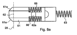
外側摺動体61及び内側摺動体62はそれぞれ、以下のように協働する(図8a及び8b参照)。図8及び8aには、摺動体を下方から、すなわちシリンダコア20の内部から見た図が示されている。内側摺動体62は、外側摺動体61の底面に設けられた溝内に配置されるため、軸方向に移動するように案内される。内側摺動体62は、2つの弾性手段(図示される実施形態ではばね66)によって、外側摺動体61に対して、図8aに示される位置にばね付勢される。すなわち、内側摺動体62の休止位置においては、内側摺動体62の外端部は外側摺動体61の外端面から突出しない。
The outer sliding
内側摺動体62が、例えば内側摺動体ピン62a及びアクチュエータ肩部65aの協働によって、移動しないように保持されているとしても、外側摺動体61は依然として、図8aに示される位置から右側に自由に移動することができる。この移動中に、ばね66は図8bに示されるように圧縮されて、内側摺動体62の外端部が外側摺動体61の外端部から突出する。
Even though the
自由回転作動(すなわち施錠装置1のロック位置)について、主として図9a、9b乃至14a、14bを参照しながら説明する。図9aは施錠装置1の上面図を示し、図9bは、図9aの施錠装置の円で囲まれた部分の拡大図を示す。シリンダコア20の長手方向溝26内に設けられた外側摺動体61は、アダプタ40の端部に設けられたフランジ46の1つと整合する。このフランジ46によって、外側摺動体は、ばね63が圧縮される内端位置で保持される。
The free rotation operation (that is, the lock position of the locking device 1) will be described with reference mainly to FIGS. 9a, 9b to 14a, 14b. 9a shows a top view of the locking device 1 and FIG. 9b shows an enlarged view of the circled portion of the locking device of FIG. 9a. The outer sliding
肩部65aが内側摺動体62のタップ62aの動きを妨げない回転位置にアクチュエータ65がある(図11b参照)ため、図8a及び8bについて上で説明されたように、この内側摺動体は、外側摺動体に対して相対移動する。
Since the
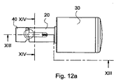
ノブ30がシリンダコア20とともに回転すると、外側摺動体61及び内側摺動体62は、フランジ46と整合した状態から抜け出して移動する。これは、両摺動体が図12b(図8aに対応する)に示す延出位置に移動できることを意味する。このとき、両摺動体の外端部は、シリンダコア20の内端面28から延出する。この移動は、ばね63の力によって生じるものである。
When the
シリンダコア20が図12bに示されている位置から回転すると、外側摺動体の外端部が最終的にはアダプタのフランジ46の別の一つと接触する。次いで、外側摺動体61及び内側摺動体62が、外側摺動体61の傾斜端面61aによって、図9a及び9bに示される内端位置に押される。この移動は、内側摺動体62が外側摺動体61とともに移動するため、ばね63の力に抗して行なわれる。
As the
摺動体61、62は、回転中にフランジ46と接触する度に、ばね63のみの力に抗して、各摺動体の外端位置からに内端位置へと押されるため、使用者は、ノブ30が回されると、シリンダコア20とアダプタ40との間の自由回転を経験する。したがって、ノブ30が回されるときに、アダプタ40はほぼ静止した状態を保ち、これにより、施錠装置1の施錠作動状態を提供する。
Each time the sliding
図15a、b乃至17a、bを参照して、施錠装置1の非施錠作動状態について説明する。前述された施錠作動状態と非施錠作動状態の一つの基本的な違いは、アクチュエータ65が非施錠作動中は回転位置を有することであり、その肩部65aが内側摺動体62のピン62aと整合することにより、例えば図12a、b及び図15a、bで示されている、内側摺動体の外端位置からの摺動が妨げられる。図16bには、肩部65aが、アダプタ40から見てピン62aの「背後」に位置する様子を示しており、これにより、上述した外端位置からの移動を防止し、又は阻止する。
With reference to FIG. 15a, b thru | or 17a, b, the non-locking operation state of the locking device 1 is demonstrated. One fundamental difference between the locked and unlocked operating states described above is that the
外側摺動体61の移動は、アクチュエータによっては防がれないことに注意されたい。これは、外側摺動体61がノブ30及びシリンダコア20の回転中にフランジ46の一つと接触するときに、該外側摺動体が、図9a、b乃至14a、bについて上述したが、今回は外側摺動体ばね63および内側摺動体ばね66の組み合わされた力に抗して、施錠作動状態又は自由回転作動状態にあるときのような内端位置へと押されることを意味する。
It should be noted that the movement of the outer sliding
内側摺動体62が外端位置に残る(図8bに対応する図15a、bを参照)ため、アダプタのフランジ46が内側摺動体62に当接すると、内側摺動体は、シリンダコア20とアダプタ40の間のそれ以上の相対回転を阻止する。これは、内側摺動体が、回転方向にほぼ直交する当接面をフランジに対して露出するためである。図15bの矢印方向にシリンダコア20をさらに回転させると、シリンダコアの内側摺動体62とアダプタのフランジ46との間の相互作用によって、アダプタ40の対応する回転がもたらされる。これにより、テールピース50によってアダプタ40に接続される上述したロック機構が非施錠作動位置とされる。
Since the inner sliding
アダプタ65の肩部65aに加えられる唯一の力が、内側摺動体のばね66のばね力であることは理解されよう。これらの内側摺動体ばね66は比較的弱く形成することができるため(これらの唯一の機能は、外側摺動体がその外端位置から移動されたときに内側摺動体62を外側摺動体61に対して確実に相対移動させることである)、アクチュエータ65に及ぼされる力は相対的に小さく、これは、アクチュエータの寸法において有利である。
It will be appreciated that the only force applied to the
アクチュエータ65が図16b及び17bに示される位置から図13b及び14bに示される位置に移動されると、内側摺動体ばね66は、内側摺動体62を、相対的に外側摺動体61に向かった位置に移動させ、このとき、内側摺動体62の外端と外側摺動体61の外端は同一平面上に位置する。すなわち、肩部65a及びピン62aが係合状態でなくなるようにアクチュエータを移動させることにより、施錠装置1が自由回転作動状態に戻る。
When the
本発明による施錠装置の好ましい実施形態について説明してきたが、当業者であれば、添付の特許請求の範囲の範囲内において、該実施形態に変更を加え得ることは理解されよう。このため、ノブ作動式施錠装置について図示し、説明してきたが、本発明の技術思想は、キー操作式ロックシリンダのような他の種類のロックシリンダにも適用することができることは理解されよう。 Having described preferred embodiments of the locking device according to the present invention, those skilled in the art will appreciate that modifications may be made to the embodiments within the scope of the appended claims. Thus, although the knob actuated locking device has been illustrated and described, it will be appreciated that the technical idea of the present invention can be applied to other types of lock cylinders such as key operated lock cylinders.
記載されるロックにおいて提供される摺動構成は、アダプタの介在なく、ロック機構に直接作用することができる。したがって、本発明の技術思想は、連結手段が、ハンドル等によって回転可能なシリンダコア又は同様の構成と、ロック機構に作用するテールピースとの間に作用する、任意の実施形態を包含するものである。 The sliding arrangement provided in the described lock can act directly on the locking mechanism without the intervention of an adapter. Therefore, the technical idea of the present invention encompasses any embodiment in which the connecting means acts between a cylinder core or similar structure that can be rotated by a handle or the like and a tailpiece that acts on the locking mechanism. is there.
Claims (10)
連結手段が、
前記シリンダコアの内端面から延出する外端位置と、該シリンダコアの内端面から延出しない内端位置との間で軸方向に移動可能な第1部品(61)であって、延長部と係合している間は、該第1部品を外端位置から内端位置へ移動させる構成を有する第1部品(61)と、
前記シリンダコアの内端面から延出する外端位置と、該シリンダコアの内端面から延出しない内端位置との間で軸方向に移動可能な第2部品(62)と、
前記第2部品の外端位置からの移動を阻止する阻止位置と、前記第2部品の外端位置からの移動を許容する非阻止位置との間で移動可能な妨害手段(65、65a)と、
前記妨害手段が非阻止位置にあるときに、前記第2部品が前記第1部品の移動に追従するように、前記連結手段の第1部品と第2部品との間に配置される弾性手段(66)と
を備える、施錠装置。 A cylinder housing (10), a substantially cylindrical cylinder core (20) having a longitudinal axis and rotatably accommodated in the cylinder housing, and an extension configured to cooperate with a locking mechanism (40, 50), wherein the cylinder core has an inner end face (28) facing the direction of the extension part,
The connecting means is
A first part (61) movable in an axial direction between an outer end position extending from an inner end face of the cylinder core and an inner end position not extending from the inner end face of the cylinder core, the extension part A first part (61) having a configuration for moving the first part from the outer end position to the inner end position while being engaged with;
A second part (62) movable in an axial direction between an outer end position extending from the inner end face of the cylinder core and an inner end position not extending from the inner end face of the cylinder core;
Interfering means (65, 65a) movable between a blocking position for preventing movement of the second part from the outer end position and a non-blocking position for allowing movement of the second part from the outer end position. ,
Elastic means (between the first part and the second part of the connecting means) so that the second part follows the movement of the first part when the blocking means is in the non-blocking position; 66).
Applications Claiming Priority (3)
| Application Number | Priority Date | Filing Date | Title |
|---|---|---|---|
| SE0701025-9 | 2007-04-27 | ||
| SE0701025 | 2007-04-27 | ||
| PCT/SE2008/000291 WO2008133574A1 (en) | 2007-04-27 | 2008-04-25 | Lock device |
Publications (2)
| Publication Number | Publication Date |
|---|---|
| JP2010525203A true JP2010525203A (en) | 2010-07-22 |
| JP5496878B2 JP5496878B2 (en) | 2014-05-21 |
Family
ID=39925914
Family Applications (1)
| Application Number | Title | Priority Date | Filing Date |
|---|---|---|---|
| JP2010506127A Expired - Fee Related JP5496878B2 (en) | 2007-04-27 | 2008-04-25 | Locking device |
Country Status (10)
| Country | Link |
|---|---|
| US (1) | US8459071B2 (en) |
| EP (1) | EP2140085B1 (en) |
| JP (1) | JP5496878B2 (en) |
| KR (1) | KR101503780B1 (en) |
| CN (1) | CN101668914B (en) |
| AU (1) | AU2008244687B2 (en) |
| CA (1) | CA2683126A1 (en) |
| IL (1) | IL201747A (en) |
| NZ (1) | NZ579688A (en) |
| WO (1) | WO2008133574A1 (en) |
Cited By (1)
| Publication number | Priority date | Publication date | Assignee | Title |
|---|---|---|---|---|
| JP2022107574A (en) * | 2020-01-21 | 2022-07-22 | ラチ システムズ,インコーポレイテッド | Lock mechanism |
Families Citing this family (11)
| Publication number | Priority date | Publication date | Assignee | Title |
|---|---|---|---|---|
| US8800402B2 (en) | 2010-03-04 | 2014-08-12 | Vingcard Elsafe As | Motor mechanism |
| CA2708700C (en) * | 2010-06-29 | 2016-11-22 | Wesko Systems Limited | Releasable tenon for locking system |
| WO2012171899A1 (en) | 2011-06-16 | 2012-12-20 | Futurama Innovation Ab | Torque transmitting arrangement |
| TWI473931B (en) * | 2012-01-12 | 2015-02-21 | Meir Avgamim | Computer security lock for trapezoidal security slot |
| TWI745456B (en) | 2016-10-19 | 2021-11-11 | 美商貝斯特艾瑟斯解決方案股份有限公司 | Electromechanical core apparatus, system, and methods of operating an electromechanical core apparatus |
| WO2019051337A1 (en) | 2017-09-08 | 2019-03-14 | Dormakaba Usa Inc. | Electro-mechanical lock core |
| US11466473B2 (en) | 2018-04-13 | 2022-10-11 | Dormakaba Usa Inc | Electro-mechanical lock core |
| CN112752891B (en) | 2018-04-13 | 2022-08-05 | 多玛卡巴美国公司 | Electromechanical lock cylinder |
| SE545664C2 (en) * | 2020-01-23 | 2023-11-28 | Assa Abloy Ab | Actuating device with electromechanical coupling device including blocker, holder and manually actuated release mechanism, and lock device |
| US12152409B2 (en) | 2022-04-15 | 2024-11-26 | Security People, Inc. | Electronic mortise lock cylinder |
| US11655653B1 (en) | 2022-04-15 | 2023-05-23 | Digilock Asia Ltd. | Electronically operated lock cylinder |
Citations (1)
| Publication number | Priority date | Publication date | Assignee | Title |
|---|---|---|---|---|
| JP2005023782A (en) * | 2003-06-12 | 2005-01-27 | Nobuyo Sakai | Electric cylinder for cylinder door lock operation and cylinder door lock |
Family Cites Families (21)
| Publication number | Priority date | Publication date | Assignee | Title |
|---|---|---|---|---|
| AU566903B2 (en) * | 1982-11-26 | 1987-11-05 | Bauer Kaba Ag | Electromagnetic cylinder lock |
| AT381132B (en) * | 1984-10-04 | 1986-08-25 | Evva Werke | LOCKING CYLINDER WITH A HOUSING AND A CORE |
| AT380301B (en) * | 1984-11-26 | 1986-05-12 | Evva Werke | LOCKING CYLINDERS WITH A HOUSING AND A ROTATING, ONE OR MULTIPLE LOCKING, IN PARTICULAR MAGNETIC ROTORS CARRYING A CORE |
| CH668616A5 (en) * | 1985-12-19 | 1989-01-13 | Bauer Kaba Ag | LOCKING DEVICE FOR A MECHANICAL / ELECTRONIC LOCKING SYSTEM. |
| CN87203432U (en) * | 1987-07-07 | 1988-03-23 | 刘冰 | Spring lock core being capable of drawout and replacing keys |
| SE505493C2 (en) * | 1992-03-26 | 1997-09-08 | Assa Ab | Cylinder |
| DE19807553C1 (en) * | 1998-02-23 | 1999-07-01 | Keso Gmbh | Lock cylinder operating drive |
| DE19824713A1 (en) * | 1998-06-03 | 1999-12-16 | Dom Sicherheitstechnik | Door lock cylinder with internal rotating members |
| DE19834691A1 (en) * | 1998-07-31 | 2000-02-03 | Wilke Heinrich Hewi Gmbh | Locking system |
| SE515562C2 (en) * | 1998-09-23 | 2001-08-27 | Lars Mattsson | Device for assisting in access control to premises and spaces |
| ES2205952B1 (en) * | 1999-07-27 | 2005-04-16 | Talleres De Escoriaza, S.A. | LOCK CYLINDER |
| DE60110103T2 (en) * | 2000-08-22 | 2006-06-01 | Kowalczyk, Piotr Leonard | LOCK |
| US6460903B1 (en) * | 2000-10-31 | 2002-10-08 | Summit Automation Co., Ltd | Locking mechanism of electronic lock |
| GB0201110D0 (en) * | 2002-01-18 | 2002-03-06 | Squire Henry & Sons | Lock cylinder assembly |
| US6865916B2 (en) * | 2002-08-28 | 2005-03-15 | Ilan Goldman | Door cylinder lock |
| US6725693B2 (en) | 2002-08-30 | 2004-04-27 | Jer Ming Yu | Door lock with a clutch having a cam-styled axle sleeve |
| CN2607420Y (en) * | 2003-03-26 | 2004-03-24 | 李明芳 | Handle auto-lock |
| US20040255628A1 (en) * | 2003-05-09 | 2004-12-23 | Herbert Meyerle | Door lock system and method |
| TW200427915A (en) * | 2003-06-12 | 2004-12-16 | Nobuyo Sakai | Electric cylinder for actuating a door lock and a cylinder door lock |
| ATE542008T1 (en) * | 2004-03-11 | 2012-02-15 | Keso Ag | ELECTROMECHANICAL LOCKING CYLINDER |
| ES2331865B1 (en) * | 2008-07-15 | 2010-10-28 | Salto Systems, S.L. | CLUTCH MECHANISM APPLICABLE TO ELECTROMECHANICAL CYLINDERS OF LOCKS. |
-
2008
- 2008-04-25 NZ NZ579688A patent/NZ579688A/en unknown
- 2008-04-25 US US12/596,870 patent/US8459071B2/en not_active Expired - Fee Related
- 2008-04-25 AU AU2008244687A patent/AU2008244687B2/en not_active Ceased
- 2008-04-25 WO PCT/SE2008/000291 patent/WO2008133574A1/en not_active Ceased
- 2008-04-25 EP EP08741865.3A patent/EP2140085B1/en active Active
- 2008-04-25 CA CA 2683126 patent/CA2683126A1/en not_active Abandoned
- 2008-04-25 CN CN2008800137558A patent/CN101668914B/en not_active Expired - Fee Related
- 2008-04-25 KR KR1020097020602A patent/KR101503780B1/en not_active Expired - Fee Related
- 2008-04-25 JP JP2010506127A patent/JP5496878B2/en not_active Expired - Fee Related
-
2009
- 2009-10-25 IL IL201747A patent/IL201747A/en active IP Right Grant
Patent Citations (1)
| Publication number | Priority date | Publication date | Assignee | Title |
|---|---|---|---|---|
| JP2005023782A (en) * | 2003-06-12 | 2005-01-27 | Nobuyo Sakai | Electric cylinder for cylinder door lock operation and cylinder door lock |
Cited By (1)
| Publication number | Priority date | Publication date | Assignee | Title |
|---|---|---|---|---|
| JP2022107574A (en) * | 2020-01-21 | 2022-07-22 | ラチ システムズ,インコーポレイテッド | Lock mechanism |
Also Published As
| Publication number | Publication date |
|---|---|
| JP5496878B2 (en) | 2014-05-21 |
| KR101503780B1 (en) | 2015-03-18 |
| AU2008244687A1 (en) | 2008-11-06 |
| EP2140085A1 (en) | 2010-01-06 |
| CA2683126A1 (en) | 2008-11-06 |
| KR20100015334A (en) | 2010-02-12 |
| IL201747A0 (en) | 2010-06-16 |
| EP2140085B1 (en) | 2016-01-13 |
| IL201747A (en) | 2015-09-24 |
| NZ579688A (en) | 2011-12-22 |
| US8459071B2 (en) | 2013-06-11 |
| CN101668914A (en) | 2010-03-10 |
| AU2008244687B2 (en) | 2014-06-26 |
| EP2140085A4 (en) | 2014-10-08 |
| WO2008133574A1 (en) | 2008-11-06 |
| CN101668914B (en) | 2012-10-17 |
| US20100139341A1 (en) | 2010-06-10 |
Similar Documents
| Publication | Publication Date | Title |
|---|---|---|
| JP5496878B2 (en) | Locking device | |
| JP6386545B2 (en) | Handle device | |
| EP2599943B1 (en) | Electronic door lock device for connecting clutch easily | |
| JP5119273B2 (en) | Locking device | |
| JP2008303699A (en) | Key equipped with swing bolt and its actuator assembly | |
| CN109790725B (en) | handle device | |
| TWI429821B (en) | Lock assembly | |
| JP5006963B2 (en) | Actuator for vehicle door latch device | |
| US20230417077A1 (en) | Locking device with a catch arrangement | |
| US20240011325A1 (en) | Locking device for mechanical and non-mechanical activation of a locking bolt | |
| SE2050711A1 (en) | Adapter for a locking device | |
| IE20070399A1 (en) | Cylinder assembly | |
| AU2014216016B2 (en) | Electronic door lock device for connecting clutch easily | |
| JP4651523B2 (en) | Actuator for vehicle door latch device |
Legal Events
| Date | Code | Title | Description |
|---|---|---|---|
| A621 | Written request for application examination |
Free format text: JAPANESE INTERMEDIATE CODE: A621 Effective date: 20110330 |
|
| RD04 | Notification of resignation of power of attorney |
Free format text: JAPANESE INTERMEDIATE CODE: A7424 Effective date: 20120119 |
|
| A977 | Report on retrieval |
Free format text: JAPANESE INTERMEDIATE CODE: A971007 Effective date: 20121026 |
|
| A131 | Notification of reasons for refusal |
Free format text: JAPANESE INTERMEDIATE CODE: A131 Effective date: 20130108 |
|
| A521 | Request for written amendment filed |
Free format text: JAPANESE INTERMEDIATE CODE: A523 Effective date: 20130405 |
|
| TRDD | Decision of grant or rejection written | ||
| A01 | Written decision to grant a patent or to grant a registration (utility model) |
Free format text: JAPANESE INTERMEDIATE CODE: A01 Effective date: 20140204 |
|
| A61 | First payment of annual fees (during grant procedure) |
Free format text: JAPANESE INTERMEDIATE CODE: A61 Effective date: 20140305 |
|
| R150 | Certificate of patent or registration of utility model |
Ref document number: 5496878 Country of ref document: JP Free format text: JAPANESE INTERMEDIATE CODE: R150 |
|
| R250 | Receipt of annual fees |
Free format text: JAPANESE INTERMEDIATE CODE: R250 |
|
| R250 | Receipt of annual fees |
Free format text: JAPANESE INTERMEDIATE CODE: R250 |
|
| R250 | Receipt of annual fees |
Free format text: JAPANESE INTERMEDIATE CODE: R250 |
|
| R250 | Receipt of annual fees |
Free format text: JAPANESE INTERMEDIATE CODE: R250 |
|
| LAPS | Cancellation because of no payment of annual fees |