JP2010253493A - Parallel seam welding method and parallel seam welding apparatus - Google Patents

Parallel seam welding method and parallel seam welding apparatus Download PDF

Info

Publication number
JP2010253493A
JP2010253493A JP2009104460A JP2009104460A JP2010253493A JP 2010253493 A JP2010253493 A JP 2010253493A JP 2009104460 A JP2009104460 A JP 2009104460A JP 2009104460 A JP2009104460 A JP 2009104460A JP 2010253493 A JP2010253493 A JP 2010253493A
Authority
JP
Japan
Prior art keywords
lid
package
parallel seam
welding
roller
Prior art date
Legal status (The legal status is an assumption and is not a legal conclusion. Google has not performed a legal analysis and makes no representation as to the accuracy of the status listed.)
Withdrawn
Application number
JP2009104460A
Other languages
Japanese (ja)
Inventor
Jun Matsuda
純 松田
Akio Komatsu
秋男 小松
Current Assignee (The listed assignees may be inaccurate. Google has not performed a legal analysis and makes no representation or warranty as to the accuracy of the list.)
Origin Electric Co Ltd
Original Assignee
Origin Electric Co Ltd
Priority date (The priority date is an assumption and is not a legal conclusion. Google has not performed a legal analysis and makes no representation as to the accuracy of the date listed.)
Filing date
Publication date
Application filed by Origin Electric Co Ltd filed Critical Origin Electric Co Ltd
Priority to JP2009104460A priority Critical patent/JP2010253493A/en
Publication of JP2010253493A publication Critical patent/JP2010253493A/en
Withdrawn legal-status Critical Current

Links

Images

Landscapes

  • Laser Beam Processing (AREA)
  • Resistance Welding (AREA)

Abstract

【課題】リッドとパッケージとの溶接不良を無くし、信頼性の高い封止構造を得る。
【解決手段】一対のローラー電極によって、リッドの対向する2辺における一方の端部をスポット溶接してリッドをパッケージに仮付けし、その仮付けした端部の最外側は仮付け前の位置の高さからは低くなっており、仮付けを行った後、ローラー電極を仮付け下端部から他方の端部に向けて、あるいはローラー電極を仮付けした箇所から引き上げてリッドの他方の端部に移動させ、そこから仮付けした端部に向けてパラレルシーム溶接を行い、次に、リッドの他方の2辺をパラレルシーム溶接してパッケージを封止する。
【選択図】図1
The present invention eliminates poor welding between a lid and a package, and provides a highly reliable sealing structure.
A pair of roller electrodes spot welds one end of two opposite sides of the lid to temporarily attach the lid to the package, and the outermost portion of the temporarily attached end is located at a position before provisional attachment. After the temporary attachment, the roller electrode is directed from the lower end of the temporary attachment toward the other end or pulled up from the place where the roller electrode is temporarily attached to the other end of the lid. Then, parallel seam welding is performed toward the temporarily attached end portion, and then the other two sides of the lid are parallel seam welded to seal the package.
[Selection] Figure 1

Description

この発明は、水晶振動子などの電子部品のチップを収納したパッケージの開口部に、金属材料からなる4角形状のリッド(蓋)をシーム溶接してパッケージを封止するパラレルシーム溶接方法及びパラレルシーム溶接装置に関する。   The present invention relates to a parallel seam welding method and a parallel seam welding method in which a rectangular lid (lid) made of a metal material is seam welded to an opening of a package containing a chip of an electronic component such as a crystal resonator and the package is sealed. The present invention relates to a seam welding apparatus.

一般に、水晶振動子のチップや半導体チップなどを収納してなるパッケージの開口部にリッドを接合して封止する方法としてパラレルシーム接合方法が用いられている。このパラレルシーム接合方法は広く知られているので詳しくは説明しないが、従来から金属材料からなるシールリングが開口部に固定されたセラミック製のパッケージを用い、そのパッケージの開口部にコバールなどからなるリッドをパラレルシーム接合して、パッケージを封止してきた。しかし、この封止構造の場合には、厚手のシールリングを用いているので、パッケージ全体の高さを低くできず、また、低コスト化も難しいなどの問題から、シールリングをもたないパッケージを用いた封止構造が普及してきている。   In general, a parallel seam bonding method is used as a method of bonding and sealing a lid to an opening of a package containing a crystal resonator chip or a semiconductor chip. This parallel seam joining method is widely known and will not be described in detail. Conventionally, a ceramic package in which a seal ring made of a metal material is fixed to an opening, and the opening of the package is made of Kovar or the like. The lid has been parallel seam bonded to seal the package. However, in the case of this sealing structure, since a thick seal ring is used, the package does not have a seal ring because the overall height of the package cannot be reduced and it is difficult to reduce the cost. Sealing structures using sapphire have become widespread.

このシールリングをもたないパッケージの開口部にリッドを接合するシーム接合方法は、一般にダイレクトパラレルシーム方法と呼ばれている。最近のダイレクトパラレルシーム方法の場合には、例えば100μm程度の薄いリッドにAg−Cu合金などからなるろう材層を予めクラッドさせておき、そのろう材層を溶融させてリッドをパッケージに接合している。しかし、ろう材層をクラッドによってリッドに形成しているために、ろう材層の厚みはメッキ膜のように数μmの厚さにはできず、一般的には十数μmを超える厚みとなっている。   This seam joining method for joining a lid to an opening of a package having no seal ring is generally called a direct parallel seam method. In the case of the recent direct parallel seam method, for example, a brazing material layer made of an Ag—Cu alloy or the like is clad in advance on a thin lid of about 100 μm, and the brazing material layer is melted to bond the lid to the package. Yes. However, since the brazing material layer is formed on the lid by the clad, the thickness of the brazing material layer cannot be as small as several μm as in the case of a plating film, and generally exceeds 10 μm. ing.

このような厚みを有するろう材層がクラッドされたリッドをパッケージにダイレクトパラレルシーム方法によって接合する際の問題を解決する従来方法が既に開示されている(例えば、特許文献1参照)。この特許文献1の発明は、リッドの対向する2辺のほぼ中央付近をスポット接合してリッドをパッケージに仮付けした後、パラレルシーム接合するときに、リッドの仮付けした2辺とは別の2辺を先ずパラレルシーム接合し、次に仮付けした2辺をパラレルシーム接合することを特徴としている。このようにすることによって、前記別の2辺をシーム接合する段階で仮付けした箇所が溶融しないので、接合不良を低減できるというものである。   There has already been disclosed a conventional method for solving the problem in bonding a lid clad with a brazing filler metal layer having such a thickness to a package by a direct parallel seam method (see, for example, Patent Document 1). The invention of this Patent Document 1 is different from the two sides where the lid is temporarily attached, when spot-joining the vicinity of the center of two opposite sides of the lid and temporarily attaching the lid to the package and then performing parallel seam joining. Two sides are first joined in parallel seam, and then the two temporarily attached sides are joined in parallel seam. By doing in this way, since the location temporarily attached in the stage which carries out the seam joining of said another 2 sides does not fuse | melt, it can reduce joining failure.

しかし、この従来のパラレルシーム接合の場合、特許文献1の発明が目的とする問題点を解決することはできるが、本発明者が鋭意研究を行った結果、特許文献1の発明ではダイレクトパラレルシーム方法による基本的な問題点を解決することはできず、歩留まりが低く、かつ信頼性の低い封止構造であることが分かった。詳しくは後述するが、仮付けの工程で仮付け箇所のろう材層が溶融し、そしてその溶融したろう材層の周りのろう材層が軟化するのに伴い、ろう材層が十数μm〜30μmと厚いこととリッドの母材が薄いことに起因して、仮付けした箇所及びその近傍のリッドがシールリングを用いた場合に比べて大きく凹むことが接合不良の原因であることをつきとめた。つまり、ろう材層が数μm程度の厚みならば、仮付けした箇所のリッドの凹みは実質的に問題にならないが、現在のろう材層は十数μm〜30μmと厚いために、仮付けした箇所のリッドがろう材層の溶融によって最大で10μm以上も沈んで凹むので、パラレルシーム接合時に、ローラー電極とその凹み箇所との接触面積が大きくなり、パルス状の溶接電流の電流密度が減少する箇所が生じる場合がある。この電流密度が減少したろう材層の箇所が溶融不良となり、この溶融不良の箇所が溶接不良を引き起こす。 However, in the case of this conventional parallel seam joining, although the problem that the invention of Patent Document 1 aims at can be solved, as a result of the present inventor's earnest research, the invention of Patent Document 1 is directed to a direct parallel seam. It was found that the basic problem with the method could not be solved, and the sealing structure had a low yield and low reliability. As will be described in detail later, the brazing filler metal layer melts in the tacking step, and the brazing filler metal layer around the molten brazing filler metal layer softens, so that the brazing filler metal layer has a thickness of more than 10 μm. It has been found that due to the fact that it is as thick as 30 μm and the base material of the lid is thin, it is the cause of the poor bonding that the part where the temporary attachment is made and the lid in the vicinity thereof are greatly recessed as compared with the case where a seal ring is used. . In other words, if the brazing material layer has a thickness of about several μm, the dent of the lid at the temporarily attached position is not substantially a problem, but the current brazing material layer is ten and several μm to 30 μm thick, so it was temporarily attached. Since the lid of the part sinks and sinks at a maximum of 10 μm or more due to the melting of the brazing material layer, the contact area between the roller electrode and the recessed part increases during parallel seam joining, and the current density of the pulsed welding current decreases. There may be places. The location of the brazing filler metal layer where the current density is reduced becomes poorly fused, and this poorly fused location causes poor welding.

次に、従来のダイレクトパラレルシーム方法の内、後述する本発明と係わりがあると判断される可能性のある従来発明について説明する(例えば、特許文献2参照)。特許文献2に開示されている発明は、4角形状のリッドの仮付けに関する発明であって、4角形状のリッドの対角線上にある一対の角部を一対のローラー電極でスポット溶接して仮付けするものである。一般にリッドをパッケージに仮付けするときには、リッドをパッケージに位置合わせし、リッドの中央部を吸着ノズルで抑えた状態で、一対のローラー電極でリッドを仮付けする。したがって、リッドが非常に小さい場合には、前記吸着ノズルが邪魔になるので、一対のローラー電極を対角線上の角部に位置させて仮付けした方がローラー電極間の間隔を広くでき、更に小型のパッケージとリッドとをダイレクトパラレルシームできるというメリットがある。特許文献2の発明は、より小型のパッケージのダイレクトパラレルシーム方法が可能であるという目的を達成するためになされたものである。   Next, of the conventional direct parallel seam methods, a conventional invention that may be determined to be related to the present invention described later will be described (for example, see Patent Document 2). The invention disclosed in Patent Document 2 is an invention related to the provisional attachment of a quadrilateral lid, in which a pair of corners on the diagonal line of the quadrilateral lid are spot welded with a pair of roller electrodes to temporarily It is a thing to attach. In general, when a lid is temporarily attached to a package, the lid is aligned with the package, and the lid is temporarily attached with a pair of roller electrodes in a state where a central portion of the lid is held by a suction nozzle. Therefore, when the lid is very small, the suction nozzle is in the way, so it is possible to widen the interval between the roller electrodes by temporarily placing the pair of roller electrodes at the corners on the diagonal line, and further reducing the size. There is an advantage that the direct parallel seam of the package and lid can be. The invention of Patent Document 2 has been made in order to achieve the object that a direct parallel seam method for a smaller package is possible.

しかし、特許文献2の発明は次のような問題点を有している。つまり、パラレルシーム接合では一対のローラー電極が平行に位置して同じ方向に同一速度で移動しながら、ローラー電極間に通電して接合するものであるが、特許文献2の発明を実現するためには、リッドの仮付け時にはそれぞれのローラー電極を対角線上に位置するリッドの角部に移動させねばならず、また、対角頂点に合致するようにローラー電極を角度θだけ回転させねばならず、そしてパラレルシーム接合をするときにはパラレルの位置にローラー電極を戻さねばならないために、ローラー電極の移動に要する時間が増えるので総体的に接合時間が長くなるという問題がある。また、ローラー電極の動きが複雑になるために、その位置検出、制御などが複雑になり、コストがアップするなどの問題がある。   However, the invention of Patent Document 2 has the following problems. In other words, in parallel seam bonding, a pair of roller electrodes are positioned in parallel and moved at the same speed in the same direction while energizing and bonding between the roller electrodes. To achieve the invention of Patent Document 2 Means that when the lid is temporarily attached, each roller electrode must be moved to the corner of the lid located diagonally, and the roller electrode must be rotated by an angle θ so as to coincide with the diagonal vertex, When parallel seam bonding is performed, the roller electrode must be returned to the parallel position, which increases the time required to move the roller electrode, resulting in a problem that the bonding time is generally increased. In addition, since the movement of the roller electrode is complicated, there are problems such as complicated detection and control of the position and an increase in cost.

特開2006−114710号公報JP 2006-114710 A 特開2003−001428号公報JP 2003-001428 A

本発明が解決しようとする問題点は、ダイレクトパラレルシーム方法においては、リッドにクラッドされたろう材層が厚いので、リッドをパッケージに仮付けするとき、仮付けした箇所のろう材層が溶融することによってリッドが凹み、この凹みに起因して溶接不良になる箇所が発生することにある。   The problem to be solved by the present invention is that, in the direct parallel seam method, the brazing material layer clad on the lid is thick, and therefore, when the lid is temporarily attached to the package, the brazing material layer at the temporarily attached portion is melted. In this case, the lid is recessed, and a portion where welding is poor due to the recess is generated.

本発明では、ろう材層がクラッドされている4角形のリッドをパッケージに仮付けする仮付け方法が、リッドの対向する一方の2辺の同一側に位置する一方の端部をスポット溶接することにより行われ、パラレルシーム溶接は仮付けされた一方の端部から他方の端部に向けて、あるいは前記他方の端部から仮付けされた一方の端部に向けて行われる。   In the present invention, a temporary attachment method in which a rectangular lid clad with a brazing material layer is temporarily attached to a package includes spot welding of one end located on the same side of one of the two opposite sides of the lid. The parallel seam welding is performed from one temporarily attached end to the other end, or from the other end to the one temporarily attached end.

本発明によれば、仮付け箇所におけるろう材層が一旦溶融したことにより生じたリッドの凹みによる影響を最小限に抑制できる。したがって、リッドとパッケージとの間のろう材層を全周に渡って一様に溶融させることができるので、リッドとパッケージとの溶接箇所に溶接不良が発生せず、歩留まりが高く、かつ信頼性の高い封止構造を提供することができる。また、ローラー電極を複雑に動かす必要が無いので、複雑な制御を行うことはなく、また、機構も複雑に変更することがないので、コストをアップすることはなく、パラレルシーム溶接全体に要する時間も長くなることはない。   According to the present invention, it is possible to minimize the influence due to the depression of the lid generated by once melting the brazing filler metal layer at the temporary attachment location. Therefore, the brazing filler metal layer between the lid and the package can be uniformly melted over the entire circumference, so that no weld failure occurs at the welded portion between the lid and the package, the yield is high, and reliability. High sealing structure can be provided. In addition, since it is not necessary to move the roller electrode in a complicated manner, complicated control is not performed, and the mechanism is not changed in a complicated manner, so that the cost is not increased and the time required for the entire parallel seam welding is reduced. Will not be long.

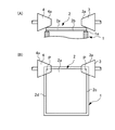
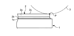
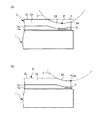
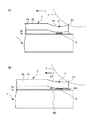
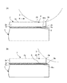
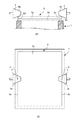
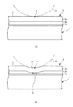
本発明の実施例1に係るパラレルシーム溶接を説明するための図である。It is a figure for demonstrating the parallel seam welding which concerns on Example 1 of this invention. 本発明の実施例1に係るパラレルシーム溶接を説明するための図である。It is a figure for demonstrating the parallel seam welding which concerns on Example 1 of this invention. 本発明の実施例1に係るパラレルシーム溶接における仮付けを説明するための図である。It is a figure for demonstrating the temporary attachment in the parallel seam welding which concerns on Example 1 of this invention. 本発明の実施例1に係るパラレルシーム溶接における仮付けした端部における通電の一例を説明するための図である。It is a figure for demonstrating an example of the electricity supply in the temporarily attached edge part in the parallel seam welding which concerns on Example 1 of this invention. 本発明の実施例2に係るパラレルシーム溶接を説明するための図である。It is a figure for demonstrating the parallel seam welding which concerns on Example 2 of this invention. 従来のパラレルシーム溶接を説明するための図である。It is a figure for demonstrating the conventional parallel seam welding. 従来のパラレルシーム溶接における仮付けを説明するための図である。It is a figure for demonstrating the temporary attachment in the conventional parallel seam welding.

先ず、本発明の実施例を説明する前に、一般的なダイレクトパラレルシーム溶接方法によってリッドをパッケージの開口部に溶接する場合における基本的な溶接メカニズム及びその問題点などについて詳述する。図6及び図7によって、ダイレクトパラレルシーム溶接における一般的な仮付けなどについて説明する。図6(A)に示すように、セラミック製のパッケージ1の開口部周縁にはシールリングが備えられておらず、メタライズ層1aが形成されている。パッケージ1の開口部周縁に形成されたメタライズ層1aに位置合わせしてリッド2が配置される。封止構造全体の高さをできるだけ低くするために、リッド2は、薄いコバールなどの母材2aの一方の面に銀ろうなどのようなろう材層2bをクラッドさせたものからなる。このろう材層2bは、前述したように母材2aにクラッドする関係上から、十数μm〜30μmの厚さである。ろう材層2bがパッケージ1のメタライズ層1a上に位置するようにリッド2を位置合わせしてパッケージ1に載せ、図示しない公知の保持手段でその状態を保持する。   First, before describing an embodiment of the present invention, a basic welding mechanism and its problems in the case where a lid is welded to an opening of a package by a general direct parallel seam welding method will be described in detail. With reference to FIGS. 6 and 7, general tacking in direct parallel seam welding will be described. As shown in FIG. 6A, the periphery of the opening of the ceramic package 1 is not provided with a seal ring, and a metallized layer 1a is formed. A lid 2 is arranged in alignment with the metallized layer 1 a formed on the periphery of the opening of the package 1. In order to make the height of the entire sealing structure as low as possible, the lid 2 is composed of a brazing material layer 2b such as silver brazing clad on one surface of a base material 2a such as a thin Kovar. The brazing filler metal layer 2b has a thickness of tens of μm to 30 μm because it is clad on the base material 2a as described above. The lid 2 is aligned and placed on the package 1 so that the brazing material layer 2b is positioned on the metallized layer 1a of the package 1, and the state is held by a known holding means (not shown).

一般的な仮付けの工程では、図6(B)に示すように、一般的な構造の一対のローラー電極3、4がリッド2の対向する一方の2辺2c、2dのほぼ中央付近に押し当てられる。このとき、図7(A)に示すように、ローラー電極3、4は2辺2c、2dとほぼ点接触で接触する。以下ではこの接触箇所を点接触箇所Pと言う。その一定位置に止まった状態で、ローラー電極3と4との間にパルス状の電流が1サイクル以上通電される。このパルス状の電流が流れるとき、ローラー電極3とリッド2との間の接触抵抗、及びローラー電極4とリッド2との間の接触抵抗によって、ローラー電極3とリッド2との間の点接触箇所P及びローラー電極4とリッド2との間の点接触箇所Pが発熱し、その発熱がリッド2の母材2aを通してろう材層2b及びメタライズ層1aに伝達され、点接触箇所Pの近傍のろう材層2bを溶融させると共に、少なくともメタライズ層1aの表面部分を溶融又は軟化させる。ろう材層2bが溶融することによって、図7(B)に示すような仮付けスポットSが形成され、リッド2がパッケージ1にスポット溶接、つまり仮付けされる。この仮付けスポットSはパラレルシーム溶接時に形成される溶接スポットに比べて小さい。   In a general tacking process, as shown in FIG. 6B, a pair of roller electrodes 3 and 4 having a general structure is pushed near the center of the two opposite sides 2c and 2d of the lid 2. Hit. At this time, as shown in FIG. 7A, the roller electrodes 3 and 4 are in contact with the two sides 2c and 2d in almost point contact. Hereinafter, this contact location is referred to as a point contact location P. A pulsed current is passed between the roller electrodes 3 and 4 for one cycle or more while staying at the fixed position. When this pulsating current flows, the point contact point between the roller electrode 3 and the lid 2 due to the contact resistance between the roller electrode 3 and the lid 2 and the contact resistance between the roller electrode 4 and the lid 2. P and the point contact point P between the roller electrode 4 and the lid 2 generate heat, and the generated heat is transmitted to the brazing material layer 2b and the metallized layer 1a through the base material 2a of the lid 2, and the solder near the point contact point P The material layer 2b is melted and at least the surface portion of the metallized layer 1a is melted or softened. When the brazing filler metal layer 2b is melted, a temporary attachment spot S as shown in FIG. 7B is formed, and the lid 2 is spot welded to the package 1, that is, temporarily attached. The tack spot S is smaller than a welding spot formed during parallel seam welding.

この理由は、リッド2がパッケージ1に仮付けされていさえすればよいという考え方が基本的にある上に、仮付けはパラレルシームに先立って最初に行われるので、パッケージ1とリッド2とが室温状態、つまり低い温度にあるので、ろう材層2b及びメタライズ層1aの温度が上昇し難く、また、蓄熱現象の問題をできるだけ避けるために必要以上に大きな電流を流さないからである。   This is because the basic idea is that the lid 2 only needs to be temporarily attached to the package 1, and since the attachment is first performed prior to the parallel seam, the package 1 and the lid 2 are kept at room temperature. This is because the temperature of the brazing filler metal layer 2b and the metallized layer 1a is not easily raised because it is in a state, that is, at a low temperature, and more current than necessary is not passed to avoid the problem of the heat storage phenomenon as much as possible.

一対のローラー電極3、4はテーパー面3a、4aを有し、そのテーパー面3a、4aがリッド2の対向する2辺2c、2dに押し当てられる。ここで、2辺2c、2dはリッド2の平面と厚み方向の面とが直交する縁に形成される直線状のものであるので、ローラー電極3、4とリッド2の2辺2c、2dとの接触は、前述したように点接触になる。このように、点接触の状態でローラー電極3、4がリッド2の2辺2c、2dに押し当てられているので、前述したように、ローラー電極3、4とリッド2の2辺2c、2dとの点接触箇所Pの近傍のろう材層2bが溶融ないしは軟化すると、ローラー電極3、4の加圧力によって薄いリッド2の母材2aの2辺2c、2dにおける仮付けした部分はローラー電極3、4のテーパー面3a、4aの曲面(円の一部)に従って沈み込む。以下では、仮付けにより沈んでリッド2の辺2c、2dの凹んだ部分を仮付け箇所2Xと言い、部分的に拡大した仮付け箇所2Xを図7に示している。このように凹んだ仮付け箇所2Xがリッド2の2辺2c、2dの端部以外の箇所にあることが、溶接不良の原因になることを本発明者はつきとめた。   The pair of roller electrodes 3, 4 have tapered surfaces 3 a, 4 a, and the tapered surfaces 3 a, 4 a are pressed against the two opposite sides 2 c, 2 d of the lid 2. Here, since the two sides 2c and 2d are linear ones formed on the edge where the plane of the lid 2 and the surface in the thickness direction are orthogonal to each other, the two sides 2c and 2d of the roller electrodes 3 and 4 and the lid 2 This contact is a point contact as described above. Thus, since the roller electrodes 3 and 4 are pressed against the two sides 2c and 2d of the lid 2 in a point contact state, the roller electrodes 3 and 4 and the two sides 2c and 2d of the lid 2 as described above. When the brazing filler metal layer 2b in the vicinity of the point contact point P is melted or softened, the temporarily attached portions on the two sides 2c and 2d of the base material 2a of the thin lid 2 by the pressing force of the roller electrodes 3 and 4 become the roller electrode 3 4 taper surfaces 3a and 4a sink according to the curved surface (a part of a circle). In the following, the portion of the lid 2 that has been sunk due to the temporary attachment and is recessed in the sides 2c and 2d is referred to as a temporary attachment portion 2X, and a partially enlarged temporary attachment portion 2X is shown in FIG. The present inventor has found that such a recessed temporary attachment location 2X is in a location other than the ends of the two sides 2c and 2d of the lid 2, which causes welding failure.

パラレルシーム溶接では、一般に仮付け後に一対のローラー電極3、4を点接触箇所Pから上方に引き上げ、リッド2の対向する2辺2c、2dの一方の端部に移動させてから押し当る。その位置でローラー電極3と4との間にパルス状の電流の通電を開始すると共に、通電しながらローラー電極3、4を一定速度で他方の端部に向けて移行させる。前述したように、このときローラー電極3、4とリッド2の2辺2c、2dとの接触は点接触であり、ローラー電極3と4との間にパルス状の電流を流す度にその点接触箇所Pを電流密度の高い電流が流れるので、ローラー電極3、4とリッド2との点接触箇所Pの近傍のろう材層2bが溶融し、仮付けスポットSに比べて大きな溶接スポットが形成される。図示しないが、ダイレクトパラレルシーム溶接では、隣り合う溶接スポットが部分的に互いに重なり合って形成され、ろう材層2bが連続して溶融するように、ローラー電極3、4の移動速度及びパルス状の電流の幅、周波数などの条件が設定されている。   In the parallel seam welding, the pair of roller electrodes 3 and 4 are generally lifted upward from the point contact point P after temporary attachment, moved to one end of the two opposite sides 2c and 2d of the lid 2, and then pressed. At that position, energization of a pulsed current is started between the roller electrodes 3 and 4, and the roller electrodes 3 and 4 are moved toward the other end at a constant speed while being energized. As described above, at this time, the contact between the roller electrodes 3 and 4 and the two sides 2c and 2d of the lid 2 is a point contact, and every time a pulsed current flows between the roller electrodes 3 and 4, the point contact occurs. Since a current having a high current density flows through the spot P, the brazing filler metal layer 2b in the vicinity of the point contact spot P between the roller electrodes 3 and 4 and the lid 2 is melted, and a welding spot larger than the tack spot S is formed. The Although not shown, in direct parallel seam welding, adjacent welding spots are formed so as to partially overlap each other, and the moving speed of the roller electrodes 3 and 4 and the pulsed current so that the brazing filler metal layer 2b is continuously melted. Conditions such as width and frequency are set.

したがって、仮付け箇所2Xを除いては、ローラー電極3、4とリッド2の対向する2辺2c、2dとの接触は点接触であり、この点接触の状態で好ましい溶接スポットが形成されるようにパルス状の溶接電流が設定されている。しかし、ローラー電極3、4が対向する2辺2c、2dの中央付近の仮付け箇所2Xに至ると、仮付け箇所2Xがローラー電極3、4の円形と同様な円弧で凹んでいるために、仮付け箇所2Xではローラー電極3、4とリッド2の対向する2辺2c、2dとの接触は面接触となる。特に、ローラー電極3、4が図7(B)に示す位置で、仮付け箇所2Xの凹みに一致した状態でパルス状の溶接電流の通電が行われると、前記面接触の面積は最大となり、この状態では溶接電流の電流密度が小さいので、ローラー電極3、4とリッド2の2辺2c、2dとの接触箇所での発熱が小さく、ろう材層2bが溶融しないので、仮付け時に形成された仮付けスポットSの面積は大きくならず、ほとんどそのままである。   Therefore, except for the tacking location 2X, the contact between the roller electrodes 3 and 4 and the two sides 2c and 2d facing the lid 2 is a point contact, and a preferable welding spot is formed in this point contact state. The pulsed welding current is set in However, when the roller electrodes 3 and 4 reach the temporary attachment location 2X near the center of the two opposite sides 2c and 2d, the temporary attachment location 2X is recessed with an arc similar to the circular shape of the roller electrodes 3 and 4, In the tacking location 2X, the contact between the roller electrodes 3 and 4 and the two opposite sides 2c and 2d of the lid 2 is a surface contact. In particular, when energization of a pulsed welding current is performed in a state where the roller electrodes 3 and 4 are in the position shown in FIG. In this state, since the current density of the welding current is small, the heat generation at the contact point between the roller electrodes 3 and 4 and the two sides 2c and 2d of the lid 2 is small, and the brazing material layer 2b is not melted. The area of the tack spot S does not increase and remains almost the same.

また前述したように、溶接電流の通電による発熱はリッド2の母材2aとローラー電極3、4との接触面で発生し、母材2aを通して拡がってろう材層2bとメタライズ層1aの温度を上昇させるのであるが、ローラー電極3、4が凹んだ仮付け箇所2Xにあるときには発熱が小さい。したがって、伝導される熱量も小さくなるので、特に仮付けスポットS以降における仮付け箇所2Xのろう材層2bとメタライズ層1aの温度上昇が低くなる。一方、ローラー電極3、4は一定の速度で移行し、また、パルス状の溶接電流のパルス幅、振幅もほぼ一定であるので、ローラー電極3、4が仮付けスポットSを通過した後の凹んだ仮付け箇所2X内でパルス状の溶接電流が通電される場合には、前述の理由から、ろう材層2bがほとんど溶融せず、実質的に溶接スポットが形成されない場合が多い。   In addition, as described above, heat generated by energization of the welding current is generated at the contact surface between the base material 2a of the lid 2 and the roller electrodes 3 and 4, and spreads through the base material 2a to increase the temperature of the brazing material layer 2b and the metallized layer 1a. Although it raises, heat_generation | fever is small when it exists in the temporary attachment location 2X in which the roller electrodes 3 and 4 were dented. Accordingly, the amount of heat conducted is also reduced, and the temperature rise of the brazing material layer 2b and the metallized layer 1a at the tacking spot 2X particularly after the tacking spot S is reduced. On the other hand, since the roller electrodes 3 and 4 move at a constant speed and the pulse width and amplitude of the pulsed welding current are also substantially constant, the recesses after the roller electrodes 3 and 4 have passed through the tack spot S. However, when a pulsed welding current is applied in the tacking location 2X, the brazing filler metal layer 2b is hardly melted for the reasons described above, and a welding spot is not substantially formed in many cases.

また、溶接スポットが形成されても発熱が小さいためにその大きさは小さい。そして凹んだ仮付け箇所2Xでこのようなことが生じると、溶接進行方向に伝導される熱量が小さいために、ローラー電極3、4の進行方向のリッド2、ろう材層2bとメタライズ層1aの温度が高くならない。したがって、凹んだ仮付け箇所2Xから脱出した後の幾つかのパルス状の溶接電流で形成される溶接スポットは小さく、仮付けスポットSとこれに隣り合ってパラレルシーム溶接時に形成される溶接スポットとの間、また、隣り合ってパラレルシーム溶接時に形成される溶接スポットと溶接スポットとの間に、溶接スポットが重り合わない箇所が発生し、これが溶接不良を招くことになると考えられる。   Further, even if a welding spot is formed, the size of the welding spot is small because the heat generation is small. And when such a thing occurs in the recessed tacking part 2X, since the amount of heat conducted in the welding progress direction is small, the lid 2, the brazing material layer 2b and the metallized layer 1a in the traveling direction of the roller electrodes 3, 4 The temperature does not rise. Therefore, the welding spot formed by several pulsed welding currents after exiting from the recessed tacking portion 2X is small, and the tacking spot S and the welding spot formed at the time of parallel seam welding adjacent to the tacking spot S In addition, it is considered that a spot where the welding spots do not overlap each other is generated between the welding spots formed adjacent to each other during the parallel seam welding.

[実施例1]
前述した結果から、溶接結果に悪影響を及ぼす前記現象が発生しない位置に、仮付けにより凹む仮付け箇所2Xが存在すれば、パッケージの開口部全周にわたって一様にろう材層2bが溶融し、所望の封止構造を得ることができるものと考えた。実施例1では、凹んだ仮付け箇所2Xに生じる発熱の伝導なども考慮し、リッド2の対向する一方の2辺2c、2dの同一側の一方の端部で所定の仮付けを行い、仮付けした後にローラー電極3、4を仮付けした箇所の近傍の外側からリッド2の2辺2c、2dの反対側にある他方の端部に向けてパラレルシーム溶接を行う。なお、パラレルシーム溶接は不活性ガス中又は絶縁ガス中、あるいは真空中で行われる。
[Example 1]
From the results described above, if there is a temporary attachment portion 2X that is recessed by temporary attachment at a position where the phenomenon that adversely affects the welding result does not occur, the brazing filler metal layer 2b is uniformly melted over the entire periphery of the opening of the package, It was considered that a desired sealing structure could be obtained. In the first embodiment, in consideration of conduction of heat generated in the recessed tacking portion 2X, predetermined tacking is performed at one end portion on the same side of the two sides 2c and 2d facing each other. After the attachment, parallel seam welding is performed from the outside near the portion where the roller electrodes 3 and 4 are temporarily attached to the other end on the opposite side of the two sides 2c and 2d of the lid 2. The parallel seam welding is performed in an inert gas, an insulating gas, or in a vacuum.

図1〜図4によって本発明に係るダイレクトパラレルシーム方法の実施例1について説明する。図1(A)に示すように、セラミック製のパッケージ1の開口部周縁にはシールリングが備えられておらず、開口部周縁に沿って連続してメタライズ層1aが形成されている。メタライズ層1aには更にメッキ層が形成されているが、図示していない。不図示の吸着ノズルのような保持手段によって、リッド2がパッケージ1のメタライズ層1aに位置合わせして載せられ、保持される。リッド2は、薄いコバールなどの母材2aの一方の面に比較的融点の低い銀ろうなどのようなろう材層2bをクラッドさせたものからなる。このろう材層2bは、前述したように薄い母材2aに予めろう材層2bをクラッドさせる関係上から、例えば十数μm〜30μmの厚みを有している。リッド2をパッケージ1に載せた状態では、ろう材層2bがパッケージ1のメタライズ層1aに接している。   A first embodiment of the direct parallel seam method according to the present invention will be described with reference to FIGS. As shown in FIG. 1A, the periphery of the opening of the ceramic package 1 is not provided with a seal ring, and a metallized layer 1a is continuously formed along the periphery of the opening. Although a plating layer is further formed on the metallized layer 1a, it is not shown. The lid 2 is placed in alignment with the metallized layer 1a of the package 1 and held by holding means such as a suction nozzle (not shown). The lid 2 is formed by cladding a brazing material layer 2b such as silver brazing having a relatively low melting point on one surface of a base material 2a such as thin Kovar. As described above, the brazing material layer 2b has a thickness of, for example, a few tens of μm to 30 μm because the thin base material 2a is previously clad with the brazing material layer 2b. In a state where the lid 2 is placed on the package 1, the brazing material layer 2 b is in contact with the metallized layer 1 a of the package 1.

この状態で仮付け工程が行われる。本発明の実施例1では、図1(B)に示すように、パラレルの位置にある一対のローラー電極3、4はテーパー面3a、4aを有し、そのテーパー面3a、4aがリッド2の対向する2辺2c、2dの一方の端部に押し当てられる。ここで、前述したように、ローラー電極3、4とリッド2の2辺2c、2dとは端部における点接触箇所Pで接触する。図2では、点接触箇所Pにおけるローラー電極3の円形状輪郭を破線で示し、点接触箇所Pは辺2cの最外側近傍の端部に位置する。図示しないが、以下、ローラー電極4とリッド2の辺2dとについても同様であり、後述する辺2dにおける点接触箇所、凹んだ仮付け箇所、仮付けスポット、溶接スポットなどについても同様である。このように、ローラー電極3、4がリッド2の一対の2辺2c、2dの一方の端部に点接触で押し当てられ、一定位置に保持された状態で仮付けのためのパルス状の電流がローラー電極3と4との間に一つ以上通電され、双方の点接触箇所Pを仮付け可能な大きな電流が流れる。   A temporary attachment process is performed in this state. In the first embodiment of the present invention, as shown in FIG. 1B, the pair of roller electrodes 3 and 4 in parallel positions have tapered surfaces 3a and 4a, and the tapered surfaces 3a and 4a are formed on the lid 2. It is pressed against one end of the two opposite sides 2c, 2d. Here, as described above, the roller electrodes 3 and 4 and the two sides 2c and 2d of the lid 2 are in contact at the point contact point P at the end. In FIG. 2, the circular outline of the roller electrode 3 at the point contact point P is indicated by a broken line, and the point contact point P is located at the end near the outermost side of the side 2c. Although not shown in the drawings, the same applies to the roller electrode 4 and the side 2d of the lid 2, and the same applies to point contact locations, recessed temporary attachment locations, temporary attachment spots, welding spots, and the like on the side 2d described later. In this manner, the roller electrodes 3 and 4 are pressed against one end of the pair of two sides 2c and 2d of the lid 2 by point contact, and are held in a fixed position in a pulsed current for temporary attachment. One or more are energized between the roller electrodes 3 and 4, and a large current that can temporarily attach both point contact points P flows.

仮付け用の溶接電流が双方の点接触箇所Pを流れると、ローラー電極3とリッド2の辺2c、及びローラー電極4とリッド2の辺2dとの接触抵抗によって、双方の点接触箇所Pに発熱が起こり、その熱はリッド2の母材2aを通してろう材層2bに伝達され、さらにパッケージ1のメタライズ層1aに伝達される。この熱によって、図3に示すように、点接触箇所P近傍のろう材層2bが溶融ないしは軟化し、仮付けスポットSが形成されることによってリッド2がパッケージ1に仮付けされる。これに伴い、前述したようにろう材層2bの溶融ないしは軟化した部分のリッド2(母材2a)が沈むので、リッド2の2辺2c、2dの端部に凹んだ仮付け箇所2Xが形成される。   When the welding current for tacking flows through both point contact points P, the contact resistance between the roller electrode 3 and the side 2c of the lid 2 and the contact resistance between the roller electrode 4 and the side 2d of the lid 2 causes Heat generation occurs, and the heat is transmitted to the brazing material layer 2 b through the base material 2 a of the lid 2 and further to the metallized layer 1 a of the package 1. As shown in FIG. 3, the brazing filler metal layer 2 b near the point contact point P is melted or softened by this heat, and a temporary attachment spot S is formed, whereby the lid 2 is temporarily attached to the package 1. Along with this, the lid 2 (base material 2a) of the melted or softened portion of the brazing filler metal layer 2b sinks as described above, so that a temporary attachment portion 2X that is recessed at the ends of the two sides 2c and 2d of the lid 2 is formed. Is done.

図3(A)の場合は、リッド2の辺2cの端部の最外側よりも幾分内側に仮付けスポットSが形成されて仮付けが行われており、これに伴いリッド2の最外側箇所2eが沈み、図3(A)において一点鎖線Yで示すように、リッド2の辺2cの平坦な部分よりも低くなる程度に、辺2cの最外側箇所2eに近い箇所で仮付けをしている。このように、リッド2の対向する2辺2c、2dの一方の端部におけるそれぞれの最外側箇所2eに近い箇所で仮付けを行うことが大切である。望ましくは、リッドの最外側端部で行われるパラレルシーム溶接の最初(第1点目)の通電で形成される溶接スポットが仮付け時に形成された仮付けスポットの一部分に重なり合う位置に、仮付けスポットを形成する。   In the case of FIG. 3 (A), the tacking spot S is formed somewhat inside the outermost side of the end of the side 2c of the lid 2, and temporary tacking is performed. Accordingly, the outermost side of the lid 2 is formed. As shown by the one-dot chain line Y in FIG. 3 (A), the part 2e sinks, and temporary attachment is performed at a place close to the outermost part 2e of the side 2c so as to be lower than the flat part of the side 2c of the lid 2. ing. As described above, it is important to perform temporary attachment at a location close to each outermost location 2e at one end of the two opposite sides 2c and 2d of the lid 2. Desirably, tacking is performed at a position where a welding spot formed by energization at the beginning (first point) of parallel seam welding performed at the outermost end of the lid overlaps a part of the tacking spot formed at the time of tacking. A spot is formed.

図3(B)は、図2に示すようにローラー電極3がリッド2の辺2cの端部の最外側箇所2eで接触し、その最外側箇所2eで仮付けを行って仮付けスポットSを最外側箇所2eに形成した場合を示す。図3(B)の場合は、ローラー電極3がリッド2の辺2cと点接触箇所Pが辺2cの端部の最外側にあるので、パラレルシーム溶接が反対側に位置する端部から仮付けされた端部に向かって行われる場合に有効である。しかし、仮付けスポットSが冷えて固化した後(例えば十数ms程度以上経過後)に、ローラー電極3が仮付け位置から移行を開始し、仮付けスポットSと部分的に重なる位置に最初(第1点目)の溶接スポットが形成されるようにダイレクトパラレルシームを行ってもよい。なお、仮付け時において、点接触箇所Pでローラー電極3がリッド2の辺2cと点接触するとき、ローラー電極3はその半分以上の部分が辺2cの端部の最外側箇所2eから外側にはみ出していても良い。   In FIG. 3B, as shown in FIG. 2, the roller electrode 3 comes into contact with the outermost portion 2e at the end of the side 2c of the lid 2, and temporary attachment is performed at the outermost portion 2e. The case where it forms in the outermost part 2e is shown. In the case of FIG. 3 (B), since the roller electrode 3 has the side 2c of the lid 2 and the point contact point P is on the outermost side of the end of the side 2c, the parallel seam welding is temporarily attached from the end located on the opposite side. It is effective when it is performed toward the end portion. However, after the tacking spot S is cooled and solidified (for example, after about 10 ms or more), the roller electrode 3 starts to move from the tacking position and first (at a position partially overlapping the tacking spot S ( Direct parallel seam may be performed so that the first spot) welding spot is formed. At the time of temporary attachment, when the roller electrode 3 makes point contact with the side 2c of the lid 2 at the point contact point P, the roller electrode 3 has more than half of the roller electrode 3 outward from the outermost part 2e at the end of the side 2c. It may protrude.

図3(A)に示したように、仮付けが辺2cの最外側の幾分内側で行われた場合には、最外側のろう材層2が溶融せず、角部分(2e)が仮付けされていない場合がある。仮付け位置が図3(A)に示す位置の場合には、図4(A)に示すように、仮付け直後にローラー電極3を仮付け位置から外側(溶接進行方向とは逆方向)に移動させる。ローラー電極4も同様である。このとき、詳しくは図示しないが、一対のローラー電極3、4はそれらの回転中心点がリッド2の辺2c、2dの最外側箇所2eよりも外側に位置する。ローラー電極3、4が移動する間に仮付けスポットSは固化する。この移動は、ローラー電極3、4を凹んだ仮付け箇所2Xに接触させて、あるいは仮付け箇所2Xから一旦持ち上げて行われる。   As shown in FIG. 3A, when the tacking is performed somewhat inside the outermost side 2c, the outermost brazing filler metal layer 2 is not melted and the corner portion (2e) is temporarily attached. It may not be attached. When the temporary attachment position is the position shown in FIG. 3A, as shown in FIG. 4A, immediately after the temporary attachment, the roller electrode 3 is moved outward from the temporary attachment position (the direction opposite to the welding progress direction). Move. The same applies to the roller electrode 4. At this time, although not shown in detail, the pair of roller electrodes 3 and 4 have their rotation center points located outside the outermost part 2e of the sides 2c and 2d of the lid 2. The temporary attachment spot S is solidified while the roller electrodes 3 and 4 are moved. This movement is performed by bringing the roller electrodes 3 and 4 into contact with the recessed tacking location 2X or by temporarily lifting from the tacking location 2X.

そして、ローラー電極3、4がリッド2の辺2c、2dの最外側箇所2eと点接触すると直ぐにパラレルシーム溶接の第1点目の通電が行われる。パラレルシーム溶接の第1点目の通電によって、図4(A)に示すように、リッド2の最外側箇所2e近傍のろう材層2bが溶融し、仮付けスポットSの一部分を含む大きな領域で第1の溶接スポットW1が形成される。仮付け時に生じた熱によってリッド2の最外側箇所2e近傍のろう材層2bの温度が上昇していることもあって、パラレルシーム溶接の第1点目の通電時に生じる熱は、仮付けスポットSの領域に比べて大きな領域のろう材層2bを溶融させ、第1の溶接スポットW1を形成する。第1の溶接スポットW1は仮付けスポットSの一部分と重なり合う。   As soon as the roller electrodes 3 and 4 make point contact with the outermost portions 2e of the sides 2c and 2d of the lid 2, the first energization of the parallel seam welding is performed. By energizing the first point of the parallel seam welding, as shown in FIG. 4A, the brazing filler metal layer 2b in the vicinity of the outermost portion 2e of the lid 2 is melted, and in a large region including a part of the tack spot S. A first welding spot W1 is formed. Since the temperature of the brazing filler metal layer 2b in the vicinity of the outermost part 2e of the lid 2 is increased by the heat generated at the time of temporary attachment, the heat generated at the time of energization at the first point of the parallel seam welding is a temporary attachment spot. The brazing filler metal layer 2b in a larger area than the S area is melted to form the first welding spot W1. The first welding spot W1 overlaps a part of the tack spot S.

つまり、パラレルシーム溶接の第1点目の通電はリッド2の辺2c、2dの最外側箇所2eで行われるので、それぞれに形成される第1の溶接スポットW1の位置はほぼ一定であり、第1の溶接スポットW1と一部分が重なり合う位置にそれぞれの仮付けスポットSが形成されるように仮付けを行うのが好ましい。このように、実施例1では、パラレルシーム溶接の第1点目の通電がリッド2の辺2c、2dの最外側箇所2eで行われることを前提にして、仮付け時における一対のローラー電極3、4とリッド2の対向する2辺2c、2dとの点接触箇所Pの位置は決められる。なお、このとき、リッド2の角部の最外側のろう材層2bも溶融するので、角部の溶接強度が向上し、封止構造の信頼度が向上する。   That is, since the first energization of the parallel seam welding is performed at the outermost portion 2e of the sides 2c and 2d of the lid 2, the position of the first welding spot W1 formed on each side is substantially constant, It is preferable to perform temporary attachment so that each temporary attachment spot S is formed at a position where one welding spot W1 partially overlaps. As described above, in Example 1, the pair of roller electrodes 3 at the time of temporary attachment is premised on that the first energization of the parallel seam welding is performed at the outermost portion 2e of the sides 2c and 2d of the lid 2. 4, the position of the point contact point P between the two sides 2c and 2d of the lid 2 facing each other is determined. At this time, since the outermost brazing filler metal layer 2b at the corner of the lid 2 is also melted, the welding strength at the corner is improved and the reliability of the sealing structure is improved.

一対のローラー電極3、4が溶接進行方向(図4で左方向)に移動し、少なくともパラレルシーム溶接の第2点目の通電は凹んだ仮付け箇所2Xにかかった箇所で行われるものとする。通常のパラレルシーム溶接では、第2点目の通電が行われるときには、第1点目の通電で形成された第1の溶接スポットW1は固化している。つまり、通電の順番で形成される溶接スポットは溶融と固化とを順に繰り返しながらパラレルシーム溶接が行われるので、それぞれの溶接スポットが形成されるときには直ぐ前に形成された溶接スポットは固化している。ローラー電極3、4と2辺2c、2dが面接触となる。その面接触の面積が最大の場合であっても、図3(B)に一点鎖線で示してあるように、リッド2の最外側箇所2eは沈んでいるので、従来に比べて接触面積が小さいこと、前述したように、仮付け時に発生した熱及び第1点目の通電で生じた熱が伝導されることによって、第2点目が通電される箇所の母材2a、ろう材層2b、メタライズ層1aは室温よりもかなり高い温度に上昇していることから、ろう材層2bの大きな領域で溶融が行われ、第2点目の大きな溶接スポットW2が形成される。この溶接スポットW2は仮付けスポットSを含んで、第1の溶接スポットW1の一部分と互いに重なり合い、良好なシーム構造を形成する。なお、第3点目の通電などが凹んだ仮付け箇所2Xにかかった箇所で行われる場合があっても同様である。   The pair of roller electrodes 3 and 4 are moved in the welding progress direction (leftward in FIG. 4), and at least the second point of the parallel seam welding is energized at a place on the recessed temporary attachment place 2X. . In normal parallel seam welding, when energization at the second point is performed, the first welding spot W1 formed by energization at the first point is solidified. In other words, since the welding spot formed in the order of energization is performed by parallel seam welding while sequentially repeating melting and solidification, the welding spot formed immediately before each welding spot is solidified. . The roller electrodes 3 and 4 and the two sides 2c and 2d are in surface contact. Even when the area of the surface contact is maximum, the outermost part 2e of the lid 2 is sunk as shown by the one-dot chain line in FIG. In addition, as described above, the heat generated at the time of temporary attachment and the heat generated by the energization of the first point are conducted, whereby the base material 2a, the brazing material layer 2b, where the second point is energized, Since the metallized layer 1a has risen to a temperature considerably higher than room temperature, melting is performed in a large region of the brazing material layer 2b, and a second large welding spot W2 is formed. The welding spot W2 includes the tack spot S and overlaps with a part of the first welding spot W1 to form a good seam structure. The same applies to the case where the third energization or the like is performed at a portion of the tacked portion 2X that is recessed.

次に、通常のパラレルシーム溶接と同様にして、図4(A)に示すように第2点目のパルス状の溶接電流を通電すると、仮付けスポットS又は第1点目の溶接スポットW1と重なり合う箇所に第2点目の溶接スポットW2が形成される。第3点目以降のパルス状の溶接電流の通電によって形成されるそれぞれの溶接スポットについては特に説明しないが、第3点以降の通電は凹んだ仮付け箇所2Xの外側で行われるものとすると、途中には凹んだ仮付け箇所2Xが存在せず、一対のローラー電極3、4と2辺2c、2dとは点接触でパラレルシーム溶接が行われるので、他方の端部まで隣り合う溶接スポットが重なり合って溶接される。次に、一対のローラー電極3、4はリッド2の別の対向する2辺の端部に移動し、そこから通常のパラレルシーム溶接と同様に溶接が行われる。この2辺のパラレルシーム溶接に関しては従来のパラレルシーム溶接なので、説明を行わない。   Next, in the same manner as in ordinary parallel seam welding, when a second pulse-shaped welding current is applied as shown in FIG. 4A, the temporary spot S or the first spot welding spot W1 A second welding spot W2 is formed at the overlapping portion. The welding spots formed by the energization of the pulsed welding current after the third point will not be particularly described, but the energization after the third point is assumed to be performed outside the recessed temporary attachment location 2X. There is no recessed tacking spot 2X in the middle, and parallel seam welding is performed by point contact between the pair of roller electrodes 3, 4 and the two sides 2c, 2d, so that there is an adjacent welding spot to the other end. Overlapping and welding. Next, the pair of roller electrodes 3 and 4 move to the ends of the two opposite sides of the lid 2, and welding is performed therefrom in the same manner as in normal parallel seam welding. The parallel seam welding on the two sides is a conventional parallel seam welding and will not be described.

[実施例2]
この実施例2では、前述したようにリッド2の対向する2辺2c、2dの一方の端部で仮付けを行い、その端部とは反対側に位置する他方の端部からパラレルシーム溶接を行うものである。他方の端部でのパラレルシーム溶接は従来方法と同様でよいので説明を省略する。一対のローラー電極3、4を仮付けした端部から他方の端部に移動させ、ローラー電極3、4を図5で左側から右側(矢印Kの方向)に移行させてパラレルシーム溶接を行う。前記他方の端部から一方の端部における仮付け箇所に至るまでは、ローラー電極3、4と2辺2c、2dとが点接触の状態でパラレルシーム溶接が行われるので、全く問題がない。したがって、一対のローラー電極3、4が一方の端部における凹んだ仮付け箇所2Xに至ったときの通電に関連して、図5により説明する。
[Example 2]
In the second embodiment, as described above, temporary attachment is performed at one end of the two opposite sides 2c and 2d of the lid 2, and parallel seam welding is performed from the other end located on the opposite side of the end. Is what you do. Since the parallel seam welding at the other end may be the same as the conventional method, the description thereof is omitted. The pair of roller electrodes 3 and 4 are moved from the temporarily attached end portion to the other end portion, and the roller electrodes 3 and 4 are moved from the left side to the right side (in the direction of arrow K) in FIG. 5 to perform parallel seam welding. Since parallel seam welding is performed in a state of point contact between the roller electrodes 3 and 4 and the two sides 2c and 2d from the other end portion to the temporary attachment portion at the one end portion, there is no problem at all. Therefore, FIG. 5 demonstrates in connection with electricity supply when a pair of roller electrode 3 and 4 reaches the recessed attachment part 2X in one edge part.

図5(A)はローラー電極3が一方の端部における凹んだ仮付け箇所2Xに至った状態を示しており、そこに至るまでのろう材層2bとメタライズ層1aとが溶融して溶接層Wを形成している。溶接層Wはパラレルシーム溶接の通電の度に形成された溶接スポットが重なり合って形成されたものであり、連続した層を形成している。この溶接層Wによってリッド2はパッケージ1に良好に溶接される。   FIG. 5A shows a state in which the roller electrode 3 has reached the recessed tacking portion 2X at one end, and the brazing filler metal layer 2b and the metallized layer 1a are melted to reach the weld layer. W is formed. The weld layer W is formed by overlapping weld spots that are formed each time the parallel seam welding is energized, and forms a continuous layer. The lid 2 is well welded to the package 1 by the weld layer W.

仮付けが図3(A)に示す位置で行われた場合、図5(A)に示すように、ローラー電極3が一方の端部における凹んだ仮付け箇所2Xに至ると、ローラー電極3と辺2cとの接触は面接触になる。しかし、図3(A)において一点鎖線Yで示すように、仮付け時にリッド2の最外側箇所2eが沈み込んでいるので、前記面接触は最大の場合でも従来よりも小さこと、かつ凹んだ仮付け箇所2Xが端部に形成されているので、それまでのパラレルシーム溶接によって発熱した熱が外部に放熱され難く、仮付け箇所2Xのろう材層2bとメタライズ層1aの温度がかなり上昇していることなどの理由から、大きな領域のろう材層2bとメタライズ層1aが溶融し、溶接スポットWmを形成する。この溶接スポットWmは仮付けスポットSと部分的に重なり合う、又は仮付けスポットSを包含する大きな領域のものであり、それまでの通電で形成された溶接層Wと重なり合い、連続した溶接層Wを形成している。   When the temporary attachment is performed at the position shown in FIG. 3 (A), as shown in FIG. 5 (A), when the roller electrode 3 reaches the recessed temporary attachment part 2X at one end, The contact with the side 2c is a surface contact. However, as indicated by the alternate long and short dash line Y in FIG. 3A, the outermost portion 2e of the lid 2 is sunk at the time of temporary attachment, so that the surface contact is smaller than that in the conventional case and is recessed. Since the temporary attachment part 2X is formed at the end, the heat generated by the parallel seam welding so far is hardly dissipated to the outside, and the temperature of the brazing filler metal layer 2b and the metallized layer 1a at the temporary attachment part 2X rises considerably. For example, the brazing filler metal layer 2b and the metallized layer 1a in a large area are melted to form a welding spot Wm. The welding spot Wm partially overlaps the tack spot S or is a large area including the tack spot S, overlaps with the weld layer W formed by the current energization, and forms a continuous weld layer W. Forming.

次に、ローラー電極3をさらに右側(矢印Kの方向)に移行させ、図5(B)で示すように、ローラー電極3の一部分が辺2cの最外側箇所2eから飛び出した位置で通電が行われる。この通電で、角部のろう材層2bとメタライズ層1aが溶融し、最外側の溶接スポットWnを形成する。この最外側の溶接スポットWnはその直前の通電によって形成された溶接スポットWmと互いに重なり合い、最外側のろう材層2bまでも溶融させ、信頼性の高い封止構造を形成する。その後、一対のローラー電極3、4はリッド2の別の対向する2辺の端部に移動し、そこから通常のパラレルシーム溶接と同様に溶接が行われる。実施例2の場合には、仮付けが図3(B)に示したように、最外側で仮付けされていても前述と同様にパラレルシーム溶接を行うことができこのことは容易に理解できるので、説明を省略する。   Next, the roller electrode 3 is further moved to the right side (in the direction of the arrow K), and energization is performed at a position where a part of the roller electrode 3 protrudes from the outermost portion 2e of the side 2c as shown in FIG. Is called. By this energization, the brazing filler metal layer 2b and the metallized layer 1a are melted to form the outermost welding spot Wn. The outermost welding spot Wn overlaps with the welding spot Wm formed by the energization immediately before it, and the outermost brazing filler metal layer 2b is also melted to form a highly reliable sealing structure. Thereafter, the pair of roller electrodes 3 and 4 moves to the ends of the two opposite sides of the lid 2, and welding is performed therefrom in the same manner as normal parallel seam welding. In the case of Example 2, as shown in FIG. 3B, parallel seam welding can be performed in the same manner as described above even if the temporary attachment is performed on the outermost side, and this can be easily understood. Therefore, explanation is omitted.

したがって、リッド2の対向する2辺2c、2dの一方の端部で仮付けを行い、その仮付けした一方の端部から一対のローラー電極3、4を反対側の他の端部まで移動させ、その端部からパラレルシーム溶接を開始し、仮付けの行われた一方の端部までパラレルシームを行うことによって、仮付け時に対向する2辺2c、2dに形成される凹んだ仮付け箇所2Xに起因する溶接不良を確実に防ぐことができ、信頼性の高いパッケージの封止構造を得ることができる。   Therefore, temporary attachment is performed at one end of the two opposite sides 2c and 2d of the lid 2, and the pair of roller electrodes 3 and 4 are moved from the temporarily attached end to the other end on the opposite side. The parallel seam welding is started from the end portion, and the parallel seam is performed up to one end portion where the temporary attachment is performed, thereby forming the recessed temporary attachment portions 2X formed on the two sides 2c and 2d facing each other at the time of temporary attachment. It is possible to reliably prevent poor welding due to the above, and to obtain a highly reliable package sealing structure.

不活性ガス中又は絶縁ガス中、あるいは真空中で、水晶振動子あるいは半導体チップなどを封入してなるパッケージの封止構造を形成するのに適用できる。   The present invention can be applied to forming a package sealing structure in which a crystal resonator or a semiconductor chip is sealed in an inert gas, an insulating gas, or a vacuum.

1・・・パッケージ
1a・・・パッケージ1の開口部に形成されたメタライズ層
2・・・リッド
2a・・・リッド2の母材
2b・・・母材2aにクラッドされたろう材層
2c、2d・・・リッド2の互いに対向する辺
2e・・・辺2c(2d)の最外側箇所
2X・・・辺2c(2d)における仮付け箇所
3、4・・・一対のローラー電極
3a、4a・・・ローラー電極3、4の各テーパー面
P・・・ローラー電極3(4)と辺2c(2d)との点接触箇所
S・・・仮付けスポット
W・・・ろう材層2とメタライズ層1aとにより形成された溶接層
W1・・・第1の溶接スポット
W2・・・第2の溶接スポット
Wm・・・仮付け箇所2Xにおける通電により形成された溶接スポット
Wn・・・最外側に形成された溶接スポット
J・・・パラレルシーム溶接の方向を示す矢印
K・・・パラレルシーム溶接の方向を示す矢印
DESCRIPTION OF SYMBOLS 1 ... Package 1a ... Metallization layer formed in the opening part of the package 2 ... Lid 2a ... Base material of the lid 2 2b ... Brazing material layer 2c, 2d clad by the base material 2a ... the opposite sides 2d of the lid 2 ... the outermost part of the side 2c (2d) 2X ... the temporary attachment part in the side 2c (2d) 3, 4 ... a pair of roller electrodes 3a, 4a, .. Each tapered surface of the roller electrodes 3 and 4 P: Point contact point between the roller electrode 3 (4) and the side 2c (2d) S: Temporary spot W: Brazing material layer 2 and metallized layer Welded layer formed by 1a W1 ... 1st welding spot W2 ... 2nd welding spot Wm ... Welding spot formed by energization in temporary attachment part 2X Wn ... Formed on outermost side Welding spot J ・· Arrow indicating the direction of the arrow K · · · parallel seam welding showing the direction of the parallel seam welding

Claims (2)

電子部品のチップを収納している、シールリングを備えていないパッケージの開口部に、ろう材層がクラッドされている4角形のリッド(蓋)を載せ、前記リッドを前記パッケージに仮付けし、前記リッドのそれぞれ対向する2辺にローラー電極を押し当てて移行させながら前記ローラー電極の間に通電し、前記ろう材層を溶融させて前記リッドを前記パッケージに溶接するパラレルシーム溶接方法において、
前記仮付けは、互いにパラレルに位置する一対の前記ローラー電極を、前記リッドの対向する一方の2辺におけるそれぞれの一方の端部に位置させた状態で、前記ローラー電極の間にパルス状の電流を流してスポット溶接することにより行われ、
仮付けした前記一方の端部の最外側は、前記仮付けによって仮付け前の位置の高さからは低くなっており、
前記仮付けを行った後、前記ローラー電極を前記一方の端部から他方の端部に向けて、あるいは前記ローラー電極を前記仮付けした箇所から引き上げて前記リッドの前記他方の端部に移動させ、そこから前記一方の端部に向けて、前記ローラー電極を前記リッドの対向する前記一方の2辺に押し当てて移行させながらパラレルシーム溶接を行い、
次に、前記ローラー電極を前記リッドの対向する他方の2辺に押し当てて移行させながら、パラレルシーム溶接を行って前記パッケージを封止することを特徴とするパラレルシーム溶接方法。
A rectangular lid (lid) clad with a brazing filler metal layer is placed on an opening of a package that contains a chip of an electronic component and does not have a seal ring, and the lid is temporarily attached to the package, In a parallel seam welding method in which a roller electrode is pressed against and transferred to two opposite sides of the lid and energized between the roller electrodes to melt the brazing material layer and weld the lid to the package,
In the tacking, a pair of roller electrodes positioned in parallel with each other is positioned at one end of each of the two opposite sides of the lid, and a pulsed current is applied between the roller electrodes. Flow spot welding,
The outermost side of the one end portion that has been tacked is lowered from the height of the position before tacking by the tacking,
After performing the temporary attachment, the roller electrode is moved from the one end portion toward the other end portion, or the roller electrode is lifted from the temporary attachment portion and moved to the other end portion of the lid. The parallel seam welding is performed while moving the roller electrode against the two opposite sides of the lid toward the one end portion from the one side.
Next, a parallel seam welding method is performed in which the package is sealed by performing parallel seam welding while pressing the roller electrode against the other two opposite sides of the lid and shifting.
電子部品のチップを収納している、シールリングを備えていないパッケージの開口部に、ろう材層がクラッドされている4角形のリッド(蓋)を載せ、前記リッドを前記パッケージに仮付けし、前記リッドのそれぞれ対向する2辺にローラー電極を押し当てて移行させながら前記ローラー電極の間に通電し、前記ろう材層を溶融させて前記リッドを前記パッケージに溶接するパラレルシーム溶接装置において、
互いにパラレルに位置する一対の前記ローラー電極を、前記リッドの対向する一方の2辺におけるそれぞれの一方の端部に位置させ、前記ローラー電極の間に通電することにより前記一方の端部で前記仮付けを行い、
仮付けした前記一方の端部の最外側は、前記仮付けによって仮付け前の位置の高さからは低くなっており、
前記仮付けを行った後、前記ローラー電極は前記一方の端部から他方の端部に向けて、あるいは前記ローラー電極を前記仮付けした箇所から引き上げて前記リッドの前記他方の端部に移動し、そこから前記一方の端部に向けて、前記ローラー電極を前記リッドの対向する前記一方の2辺に押し当てて移行させながらパラレルシーム溶接を行い、
次に、前記ローラー電極を前記リッドの対向する他方の2辺に押し当てて移行させながら、パラレルシーム溶接を行って前記パッケージを封止することを特徴とするパラレルシーム溶接装置。
A rectangular lid (lid) clad with a brazing filler metal layer is placed on an opening of a package that contains a chip of an electronic component and does not have a seal ring, and the lid is temporarily attached to the package, In a parallel seam welding apparatus for energizing between the roller electrodes while pressing and moving the roller electrodes against two opposite sides of the lid, and melting the brazing material layer and welding the lid to the package,
A pair of the roller electrodes positioned in parallel with each other is positioned at one end of each of the two opposite sides of the lid and energized between the roller electrodes to cause the temporary electrode at the one end. Make
The outermost side of the one end portion that has been tacked is lowered from the height of the position before tacking by the tacking,
After the temporary attachment, the roller electrode moves from the one end toward the other end, or lifts the roller electrode from the temporary attachment and moves to the other end of the lid. The parallel seam welding is performed while moving the roller electrode against the two opposite sides of the lid toward the one end portion from the one side.
Next, parallel seam welding is performed to seal the package while pressing and moving the roller electrode against the other two opposite sides of the lid.
JP2009104460A 2009-04-22 2009-04-22 Parallel seam welding method and parallel seam welding apparatus Withdrawn JP2010253493A (en)

Priority Applications (1)

Application Number Priority Date Filing Date Title
JP2009104460A JP2010253493A (en) 2009-04-22 2009-04-22 Parallel seam welding method and parallel seam welding apparatus

Applications Claiming Priority (1)

Application Number Priority Date Filing Date Title
JP2009104460A JP2010253493A (en) 2009-04-22 2009-04-22 Parallel seam welding method and parallel seam welding apparatus

Publications (1)

Publication Number Publication Date
JP2010253493A true JP2010253493A (en) 2010-11-11

Family

ID=43315037

Family Applications (1)

Application Number Title Priority Date Filing Date
JP2009104460A Withdrawn JP2010253493A (en) 2009-04-22 2009-04-22 Parallel seam welding method and parallel seam welding apparatus

Country Status (1)

Country Link
JP (1) JP2010253493A (en)

Cited By (6)

* Cited by examiner, † Cited by third party
Publication number Priority date Publication date Assignee Title
CN102157405A (en) * 2010-12-22 2011-08-17 北京时代民芯科技有限公司 Melting sealing cap-sealing process-based chip vacuum eutectic welding method
JP5574207B1 (en) * 2013-11-29 2014-08-20 アキム株式会社 Seam welding method and apparatus
JP2014230015A (en) * 2013-05-21 2014-12-08 シチズンファインテックミヨタ株式会社 Method for manufacturing piezoelectric vibrator
WO2014208629A1 (en) * 2013-06-25 2014-12-31 本田技研工業株式会社 Seam welding method and vehicular body
CN105414848A (en) * 2015-12-18 2016-03-23 安徽华东光电技术研究所 Parallel seam welding tool structure
CN118218734A (en) * 2024-05-24 2024-06-21 合肥先进封装陶瓷有限公司 A ceramic package shell automatic positioning assembly device

Cited By (9)

* Cited by examiner, † Cited by third party
Publication number Priority date Publication date Assignee Title
CN102157405A (en) * 2010-12-22 2011-08-17 北京时代民芯科技有限公司 Melting sealing cap-sealing process-based chip vacuum eutectic welding method
JP2014230015A (en) * 2013-05-21 2014-12-08 シチズンファインテックミヨタ株式会社 Method for manufacturing piezoelectric vibrator
WO2014208629A1 (en) * 2013-06-25 2014-12-31 本田技研工業株式会社 Seam welding method and vehicular body
CN105377498A (en) * 2013-06-25 2016-03-02 本田技研工业株式会社 Seam welding method and vehicular body
JP6080325B2 (en) * 2013-06-25 2017-02-15 本田技研工業株式会社 Seam welding method and vehicle body
US10335890B2 (en) 2013-06-25 2019-07-02 Honda Motor Co., Ltd. Seam welding method and vehicle body
JP5574207B1 (en) * 2013-11-29 2014-08-20 アキム株式会社 Seam welding method and apparatus
CN105414848A (en) * 2015-12-18 2016-03-23 安徽华东光电技术研究所 Parallel seam welding tool structure
CN118218734A (en) * 2024-05-24 2024-06-21 合肥先进封装陶瓷有限公司 A ceramic package shell automatic positioning assembly device

Similar Documents

Publication Publication Date Title
CN211903865U (en) Vapor chamber
JP2010253493A (en) Parallel seam welding method and parallel seam welding apparatus
JP7124131B2 (en) Method and component assembly for joining two components
KR101151569B1 (en) Welding method of stainless steel
CN107293500A (en) A kind of system in package routing method and device
JP2008194707A (en) Laser welding jig and method for manufacturing semiconductor device using the same
JP2009226420A (en) Laser welding method
JP2008028286A (en) Manufacturing method of semiconductor device
JP2008066561A (en) Manufacturing method of semiconductor device
JP2012084588A (en) Connection structure of electrode in electronic parts
TWI307286B (en) Golf head and welding method thereof
JP2020093285A (en) How to join dissimilar metals
JP4974284B2 (en) Package sealing method
JP4572984B2 (en) Laser welding structure and laser welding method
JP2012081481A (en) Connection structure of electrode in electronic component
JP4159531B2 (en) Package sealing method
JP5239187B2 (en) Laser welding member and laser welding method
JP4722930B2 (en) Welding method with fillet of two welded parts and welded part having an inclined tapered edge region therefor
KR20120019618A (en) Tap piece for generating starting arc in arc welding
CN116060765A (en) Laser welding method, welding system, control device, program product and battery
KR101319375B1 (en) High frequency brazing apparatus for bonding between ferrous and nonferrous metal
JP2010034099A (en) Hermetic sealing method
JPH04162641A (en) Laser bonding method
JP2022026626A (en) Semiconductor device and manufacturing method therefor
CN114823942B (en) Semiconductor packaging structure and packaging method

Legal Events

Date Code Title Description
A300 Withdrawal of application because of no request for examination

Free format text: JAPANESE INTERMEDIATE CODE: A300

Effective date: 20120703