JP2010253205A - Manipulator - Google Patents

Manipulator Download PDF

Info

Publication number
JP2010253205A
JP2010253205A JP2009110054A JP2009110054A JP2010253205A JP 2010253205 A JP2010253205 A JP 2010253205A JP 2009110054 A JP2009110054 A JP 2009110054A JP 2009110054 A JP2009110054 A JP 2009110054A JP 2010253205 A JP2010253205 A JP 2010253205A
Authority
JP
Japan
Prior art keywords
axis
shaft
end effector
finger
finger hook
Prior art date
Legal status (The legal status is an assumption and is not a legal conclusion. Google has not performed a legal analysis and makes no representation as to the accuracy of the status listed.)
Withdrawn
Application number
JP2009110054A
Other languages
Japanese (ja)
Inventor
Makoto Jinno
誠 神野
Current Assignee (The listed assignees may be inaccurate. Google has not performed a legal analysis and makes no representation or warranty as to the accuracy of the list.)
Terumo Corp
Original Assignee
Terumo Corp
Priority date (The priority date is an assumption and is not a legal conclusion. Google has not performed a legal analysis and makes no representation as to the accuracy of the date listed.)
Filing date
Publication date
Application filed by Terumo Corp filed Critical Terumo Corp
Priority to JP2009110054A priority Critical patent/JP2010253205A/en
Publication of JP2010253205A publication Critical patent/JP2010253205A/en
Withdrawn legal-status Critical Current

Links

Images

Landscapes

  • Surgical Instruments (AREA)
  • Manipulator (AREA)
  • Transmission Devices (AREA)

Abstract

<P>PROBLEM TO BE SOLVED: To improve operability in an operational part for operating to mechanically drive an end effector to be opened and closed. <P>SOLUTION: A manipulator 10 includes the operational part 14b including a gripper axis input part 104, a distal-end working part 12 including at least one posture axis for changing the orientation of the end effector 1300, a connecting shaft 18 for connecting the operational part 14b with the distal-end working part 12, a motor 60, 62 for driving the posture axis, and an end effector driving mechanism 1320a which mechanically transmits the manual operation of the gripper axis input part 104 to drive the end effector 1300. The part 104 is equipped with a first finger putting part 108 and a second finger putting part 110 which open and close by using an opening and closing axis 106 as a reference. The first finger putting part 108 is fixed, and the second finger putting part 110 opens and closes relatively to the first finger putting part 108. The end effector 1300 closes by closing the first finger putting part 108 and the second finger putting part 110. <P>COPYRIGHT: (C)2011,JPO&INPIT

Description

本発明は、エンドエフェクタを含む先端動作部を有するマニピュレータに関する。   The present invention relates to a manipulator having a distal end working unit including an end effector.

腹腔鏡下手術においては、患者の腹部等に小さな孔をいくつかあけて内視鏡、マニピュレータ(又は鉗子)等を挿入し、術者が内視鏡の映像をモニタで見ながら手術を行っている。このような腹腔鏡下手術は、開腹を必要としないため患者への負担が少なく、術後の回復や退院までの日数が大幅に低減されることから、適用分野の拡大が期待されている。   In laparoscopic surgery, a small hole is made in the patient's abdomen, etc., and an endoscope, manipulator (or forceps), etc. are inserted, and the surgeon performs the operation while viewing the endoscope image on the monitor. Yes. Since such laparoscopic surgery does not require laparotomy, the burden on the patient is small, and the number of days until postoperative recovery and discharge is greatly reduced, and therefore, the application field is expected to expand.

一方、腹腔鏡下手術で用いるマニピュレータには、患部の位置及び大きさに応じて迅速且つ適切な手技が可能であることが望まれており、しかも患部切除、縫合及び結紮等の様々な手技が行われる。このため、本出願人は、操作の自由度が高くしかも簡便に操作することのできるマニピュレータの提案をしている(例えば、特許文献1、特許文献2及び特許文献3参照)。   On the other hand, manipulators used in laparoscopic surgery are desired to be capable of quick and appropriate procedures depending on the position and size of the affected area, and various techniques such as excision of the affected area, suturing and ligation are required. Done. For this reason, the present applicant has proposed a manipulator that has a high degree of freedom in operation and that can be easily operated (see, for example, Patent Document 1, Patent Document 2, and Patent Document 3).

これらのマニピュレータは、基本的な構成としては、腹腔内に挿入されて手技を行う先端動作部と、操作者(一般には医師)が把持及び操作を行う操作部と、先端動作部と操作部とを接続するシャフトとを有している。操作部には、操作者が把持するグリップハンドルと、先端動作部を駆動するための複数のモータと、先端動作部のグリッパの開閉動作を指示するトリガレバーと、その他の所定の部材が設けられている。   These manipulators, as a basic configuration, include a tip operation unit that is inserted into the abdominal cavity and performs a procedure, an operation unit that an operator (generally a doctor) holds and operates, a tip operation unit and an operation unit. And a shaft for connecting. The operation unit is provided with a grip handle held by the operator, a plurality of motors for driving the tip operating unit, a trigger lever for instructing an opening / closing operation of the gripper of the tip operating unit, and other predetermined members. ing.

特開2002−102248号公報JP 2002-102248 A 特開2008−104854号公報JP 2008-104854 A 特開2008−253463号公報JP 2008-253463 A

軟性鏡下・腹腔鏡下手術に用いられている従来の一般的な鉗子では、先端動作部に加わる外力や把持する把持力等は、直接的ではないが、鉗子本体を介して手元に反作用として伝わることから、操作者はこれらの力をある程度は感じ取ることができ、適度によい操作性が得られる。しかしながら、従来の鉗子は自由度が少なく(例えば1自由度である。)、組織を把持する方向や切断する方向、縫合針の刺入方向が限られていて不便であるとともに、操作に熟練性が要求される。   With conventional general forceps used for flexible and laparoscopic surgery, the external force applied to the distal end working part and the gripping force to grip are not direct, but as a reaction to the hand through the forceps body Accordingly, the operator can feel these forces to some extent, and moderately good operability can be obtained. However, the conventional forceps have a low degree of freedom (for example, one degree of freedom), and are inconvenient due to limited gripping direction, cutting direction, and inserting direction of the suture needle, and skill in operation. Is required.

より高い自由度を得るためには、例えば、マスタ・スレーブ方式の遠隔操作型手術ロボットを適用することが考えられる。該ロボットは、高い自由度を有するとともに、患部に対して任意の方向からのアプローチが可能で、操作性に優れるという利点があるものの、先端動作部に加わる外力や把持力等はマスタ側には伝わらない。   In order to obtain a higher degree of freedom, for example, it is conceivable to apply a master / slave remote operation type surgical robot. Although the robot has a high degree of freedom and has the advantage of being able to approach the affected part from any direction and having excellent operability, the external force and gripping force applied to the tip operating part are not applied to the master side. I don't get it.

マスタ・スレーブ方式のロボットにおいて、マスタ側で力感覚を得るためには、高感度な力覚センサシステムや高速なサンプリングタイムを有する計算機システムによる高度なバイラテラル制御が必須となり、高価で複雑なシステムとなる。また、バイラテラル制御は実用に値する十分な性能が得られていないのが現状である。   In order to obtain a force sensation on the master side in a master / slave robot, advanced bilateral control using a highly sensitive force sensor system and a computer system with a fast sampling time is essential, which is an expensive and complicated system. It becomes. In addition, bilateral control has not been able to obtain practically sufficient performance.

それに対して、本出願人は、特願2007−283323号において、高い自由度が得られ、操作者が先端動作部に加わる外力等をより確実に感知することができるようなマニピュレータを提案している。このマニピュレータでは、進退動作する部材に受動ワイヤを設け、複数のプーリを介して先端のグリッパを開閉できるようにしている。これにより、グリッパとトリガが機械的に接続され、グリッパの開閉力がトリガに伝えられるとともに、グリッパの把持力を高めることができる。   On the other hand, the present applicant has proposed a manipulator in Japanese Patent Application No. 2007-283323 in which a high degree of freedom can be obtained and an operator can more reliably sense external force applied to the tip action unit. Yes. In this manipulator, a passive wire is provided on a member that moves forward and backward so that the gripper at the tip can be opened and closed via a plurality of pulleys. As a result, the gripper and the trigger are mechanically connected, the opening / closing force of the gripper is transmitted to the trigger, and the gripping force of the gripper can be increased.

一方、グリッパに対して効率的に力を加えるため、その力を適度に調整するため、さらに、グリッパからトリガに伝えられた力をさらに操作者に適切に伝達するためにはグリッパに相当する箇所の構成が重要となってくる。   On the other hand, in order to efficiently apply force to the gripper, to adjust the force appropriately, and to further properly transmit the force transmitted from the gripper to the trigger, a place corresponding to the gripper The composition of becomes important.

本発明はこれに関連してなされたものであり、人手による操作力が機械的に伝達されて開閉するエンドエフェクタをより好適に操作することのできるマニピュレータを提供することを目的とする。   The present invention has been made in connection with this, and an object of the present invention is to provide a manipulator that can more suitably operate an end effector that opens and closes when a manual operation force is mechanically transmitted.

本発明に係るマニピュレータは、人手によって操作する入力部を含む操作部と、開閉するエンドエフェクタ軸、及び該エンドエフェクタ軸の向きを変える1以上の姿勢軸を含む先端動作部と、前記操作部と前記先端動作部を連結する連結シャフトと、前記姿勢軸を駆動する姿勢軸アクチュエータと、前記入力部の人手による操作を機械的に伝達して、前記エンドエフェクタ軸を駆動する操作伝達部とを有し、前記入力部は、開閉軸を基準にして開閉する第1指掛部及び第2指掛部を備え、前記第1指掛部は固定され、前記第2指掛部が前記第1指掛部に対して相対的に開閉動作し、前記第1指掛部と前記第2指掛部が閉じることによって前記エンドエフェクタ軸が閉じることを特徴とする。   A manipulator according to the present invention includes an operation unit including an input unit operated manually, an end effector shaft that opens and closes, a tip operation unit including one or more posture axes that change the orientation of the end effector shaft, and the operation unit. A connecting shaft for connecting the distal end working unit; a posture axis actuator for driving the posture axis; and an operation transmitting unit for mechanically transmitting a manual operation of the input unit to drive the end effector shaft. The input unit includes a first finger hooking portion and a second finger hooking portion that open and close with respect to an opening / closing axis, the first finger hooking portion is fixed, and the second finger hooking portion is the first finger hooking portion. The end effector shaft is closed by opening and closing relative to the hook and closing the first finger hook and the second finger hook.

このように、固定された第1指掛部に対して第2指掛部が接近して、閉じる操作をすることによって、力をかけやすくなり操作性が向上する。また、第1指掛部と第2指掛部が閉じることによってエンドエフェクタも閉じることから、直感的な操作が可能となる。   As described above, when the second finger hook portion approaches the fixed first finger hook portion and performs the closing operation, it is easy to apply a force and the operability is improved. In addition, since the end effector is also closed by closing the first finger hook portion and the second finger hook portion, an intuitive operation is possible.

前記第1指掛部及び前記第2指掛部には、それぞれ指挿入輪が設けられていてもよい。これにより、はさみの柄と似た構成となり、慣れがあり、扱いやすい。また、エンドエフェクタに加わる力を感じやすい。閉じ方向だけでなく、開く方向にも操作しやすい。   Each of the first finger hook portion and the second finger hook portion may be provided with a finger insertion ring. Thereby, it becomes a structure similar to the pattern of scissors, is accustomed, and is easy to handle. Also, it is easy to feel the force applied to the end effector. Easy to operate not only in the closing direction but also in the opening direction.

前記第1指掛部における前記指挿入輪は、前記第2指掛部における前記指挿入輪よりも広く、前記第1指掛部の延在方向に長くしてもよい。   The finger insertion ring in the first finger hook part may be wider than the finger insertion ring in the second finger hook part and may be longer in the extending direction of the first finger hook part.

前記第2指掛部で、前記第1指掛部に対向する側と逆の側は、前記開閉軸を中心として略径方向に延在する直線形状であってもよい。これにより、親指の根元側腹部で力を加えやすく、また、エンドエフェクタに加わる力を感じやすい。   In the second finger hook portion, a side opposite to the side facing the first finger hook portion may have a linear shape extending in a substantially radial direction around the opening / closing axis. Thereby, it is easy to apply force at the base side abdomen of the thumb, and it is easy to feel the force applied to the end effector.

前記先端動作部は、前記連結シャフトの基端側から先端側に延在する軸線と非平行に回動可能なピボット軸を有し、前記連結シャフトの軸に対して直交する軸を基準として回転し、前記ピボット軸に対して動作指令を与える操作つまみを有してもよい。   The distal end working unit has a pivot shaft that can rotate non-parallel to an axis extending from the proximal end side to the distal end side of the connection shaft, and rotates with reference to an axis orthogonal to the axis of the connection shaft. An operation knob for giving an operation command to the pivot shaft may be provided.

前記開閉軸は、前記連結シャフトの軸線上又はその近傍に設けられ、前記第1指掛部は、前記連結シャフトの軸線を基準として側方に延在し、前記第2指掛部は、前記第1指掛部よりも基端側斜め側方に延在していてもよい。これにより、手がシャフトの軸線と略直角な向きとなり、操作性が向上する。   The open / close shaft is provided on or near the axis of the connection shaft, the first finger hook portion extends laterally with respect to the axis of the connection shaft, and the second finger hook portion is You may extend in the base end side diagonal side rather than the 1st finger hook part. As a result, the hand is oriented substantially perpendicular to the axis of the shaft, and the operability is improved.

前記第2指掛部は、弾性体によって設定される非操作時の初期姿勢から、前記第1指掛部の方向へ接近して閉じられるようにしてもよい。   The second finger hook portion may be closed close to the first finger hook portion from a non-operating initial posture set by an elastic body.

前記開閉軸は、前記連結シャフトの軸線上又はその近傍に設けられ、前記第1指掛部は、前記連結シャフトの軸線方向に沿って基端側に延在し、前記第2指掛部は、基端側斜め側方に延在し、弾性体によって設定される非操作時の初期姿勢から、前記連結シャフトの軸線方向に接近して前記第1指掛部の方向へ閉じられてもよい。これにより、しっかりと握ることができて力を加えやすい。非操作時には、弾性体によって初期姿勢に戻すことができる。   The open / close shaft is provided on or near the axis of the connecting shaft, the first finger hooking portion extends to the base end side along the axial direction of the connecting shaft, and the second finger hooking portion is The base end side extends obliquely to the side, and may be closed in the direction of the first finger hook portion from the initial posture during non-operation set by the elastic body, approaching the axial direction of the connecting shaft. . As a result, it is easy to apply force by grasping firmly. When not operated, the elastic body can return to the initial posture.

前記姿勢軸アクチュエータは、前記エンドエフェクタ軸を回転させるロール軸アクチュエータと、前記ロール軸アクチュエータを動作させるためのロール回転指令入力手段とを有し、前記ロール回転指令入力手段は、前記連結シャフトの軸と略同軸の軸を基準として回転することにより指令信号を発するものであってもよい。   The posture axis actuator includes a roll axis actuator that rotates the end effector axis, and a roll rotation command input unit that operates the roll axis actuator, and the roll rotation command input unit includes an axis of the connection shaft. And a command signal may be generated by rotating about a substantially coaxial axis.

前記姿勢軸アクチュエータは、前記エンドエフェクタ軸を傾動させるヨー軸アクチュエータと、前記ヨー軸アクチュエータを動作させるためのヨー軸動作指令入力手段とを有し、前記ヨー軸動作指令入力手段は、前記ロール回転指令入力手段の基端側に設けられていてもよい。   The attitude axis actuator includes a yaw axis actuator for tilting the end effector axis, and a yaw axis operation command input means for operating the yaw axis actuator, and the yaw axis operation command input means is the roll rotation It may be provided on the base end side of the command input means.

前記ロール回転指令入力手段は、表面に複数の凹凸を有してもよい。   The roll rotation command input means may have a plurality of irregularities on the surface.

本発明に係るマニピュレータによれば、固定された第1指掛部に対して第2指掛部が接近して、閉じる操作をすることによって、力をかけやすくなり操作性が向上する。また、第1指掛部と第2指掛部が閉じることによってエンドエフェクタも閉じることから、直感的な操作が可能となる。   According to the manipulator according to the present invention, when the second finger hook portion approaches the fixed first finger hook portion and performs the closing operation, it is easy to apply a force and the operability is improved. In addition, since the end effector is also closed by closing the first finger hook portion and the second finger hook portion, an intuitive operation is possible.

マニピュレータの側面図である。It is a side view of a manipulator. マニピュレータの平面図である。It is a top view of a manipulator. 操作部の斜視図である。It is a perspective view of an operation part. 図4Aは、ロール軸入力部の正面図であり、図4Bは、変形例に係るロール軸入力部の正面図である。FIG. 4A is a front view of a roll shaft input unit, and FIG. 4B is a front view of a roll shaft input unit according to a modification. 第1の変形例に係る操作部の側面図である。It is a side view of the operation part which concerns on a 1st modification. 図5と異なる把持方法で把持された第1の変形例に係る操作部の側面図である。FIG. 6 is a side view of an operation unit according to a first modification gripped by a gripping method different from that in FIG. 5. 第2の変形例に係る操作部の側面図である。It is a side view of the operation part which concerns on a 2nd modification. モータがY2方向に突出している場合の操作部の側面図である。It is a side view of an operation part in case a motor protrudes in Y2 direction. トリガレバーを十分に引いたときの、先端動作部の模式側面図である。It is a model side view of a front-end | tip operation | movement part when fully pulling a trigger lever. トリガレバーを押し出したときの、先端動作部の模式側面図である。It is a model side view of a front-end | tip operation | movement part when a trigger lever is pushed out. 先端動作部の模式構造図である。It is a schematic structure figure of a tip operation part. 先端動作部の断面側面図である。It is a section side view of a tip operation part. 先端動作部の断面平面図である。It is a section top view of a tip operation part. 先端動作部で、グリッパを閉じた状態の断面側面図である。It is a section side view in the state where the gripper was closed in the tip operation part. 先端動作部の分解斜視図である。It is a disassembled perspective view of a front-end | tip operation | movement part. エンドエフェクタ駆動機構の一部を示す模式構造図である。It is a schematic structure figure which shows a part of end effector drive mechanism. トリガレバーを操作しないときの、エンドエフェクタ駆動機構の模式側面図である。It is a model side view of an end effector drive mechanism when not operating a trigger lever. 受動ワイヤの端部の接続箇所の模式断面平面図である。It is a schematic cross-sectional top view of the connection location of the edge part of a passive wire. 受動ワイヤの端部の接続箇所の模式断面側面図である。It is a schematic cross section side view of the connection location of the edge part of a passive wire. トリガレバーを押し出したときの、第2エンドエフェクタ駆動機構の一部断面平面図である。It is a partial cross section top view of the 2nd end effector drive mechanism when a trigger lever is pushed out. トリガレバーを十分に引いたとき、第2エンドエフェクタ駆動機構の一部断面平面図である。When a trigger lever is fully pulled, it is a partial cross section top view of a 2nd end effector drive mechanism. トリガレバーを押し出したときの、第2エンドエフェクタ駆動機構の一部断面側面図である。It is a partial cross section side view of the 2nd end effector drive mechanism when a trigger lever is pushed out. 変形例に係る先端動作部の模式構造図である。It is a schematic structure figure of the tip operation part concerning a modification.

以下、本発明に係るマニピュレータについて実施の形態を挙げ、添付の図1〜図23を参照しながら説明する。   Embodiments of the manipulator according to the present invention will be described below with reference to FIGS.

図1に示すように、本実施の形態に係るマニピュレータ10は、コントローラ11に接続されている。マニピュレータ10は、基本的には医療用である。   As shown in FIG. 1, the manipulator 10 according to the present embodiment is connected to a controller 11. The manipulator 10 is basically for medical use.

コントローラ11は、マニピュレータ10の電気的な制御をする部分であり、グリップハンドル(第1指掛部)26の下端部から延在するケーブルに対してコネクタを介して接続されている。コントローラ11は、マニピュレータ10を独立的に複数台同時に制御することができる。もちろん、1台のマニピュレータ10を制御するコントローラを用いてもよい。   The controller 11 is a part that electrically controls the manipulator 10, and is connected to a cable extending from the lower end of the grip handle (first finger hook) 26 via a connector. The controller 11 can control a plurality of manipulators 10 independently. Of course, a controller that controls one manipulator 10 may be used.

マニピュレータ10は、先端動作部12に生体の一部又は湾曲針等を把持して所定の処置を行うためのものであり、通常、把持鉗子やニードルドライバ(持針器)等とも呼ばれる。   The manipulator 10 is for holding a part of a living body or a curved needle or the like on the distal end working unit 12 to perform a predetermined treatment, and is usually called a grasping forceps or a needle driver (needle holder).

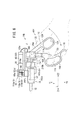
図1、図2及び図3に示すように、マニピュレータ10は、人手によって把持及び操作される操作部14aと、該操作部14aに固定された作業部16とを有する。作業部16は、作業を行う先端動作部12と、該先端動作部12と操作部14aとを連接する長尺で中空の連結シャフト18とを有する。先端動作部12及び連結シャフト18は細径に構成されており、患者の腹部等に設けられた円筒形状のトラカール20から体腔22内に挿入可能であり、複合入力部24の操作により体腔22内において患部切除、把持、縫合及び結紮等の様々な手技を行うことができる。操作部14aと作業部16とは一体構成であるが、条件に応じて分離可能な構成にしてもよい。   As shown in FIGS. 1, 2, and 3, the manipulator 10 includes an operation unit 14 a that is gripped and operated by a hand and a working unit 16 that is fixed to the operation unit 14 a. The working unit 16 includes a distal end working unit 12 that performs work, and a long and hollow connecting shaft 18 that connects the distal end working unit 12 and the operation unit 14a. The distal end working unit 12 and the connecting shaft 18 are configured to have a small diameter, and can be inserted into a body cavity 22 from a cylindrical trocar 20 provided in a patient's abdomen or the like. Various procedures such as excision of the affected area, grasping, suturing and ligation can be performed. The operation unit 14a and the working unit 16 are integrated, but may be configured to be separable according to conditions.

以下の説明では、図1及び図2における幅方向をX方向、高さ方向をY方向及び、連結シャフト18の延在方向をZ方向と規定する。また、先端側から見て右方をX1方向、左方をX2方向、上方向をY1方向、下方向をY2方向、前方をZ1方向、後方をZ2方向と規定する。さらに、特に断りのない限り、これらの方向の記載はマニピュレータ10が中立姿勢である場合を基準として表すものとする。これらの方向は説明の便宜上のものであり、マニピュレータ10は任意の向きで(例えば、上下を反転させて)使用可能であることはもちろんである。   In the following description, the width direction in FIGS. 1 and 2 is defined as the X direction, the height direction is defined as the Y direction, and the extending direction of the connecting shaft 18 is defined as the Z direction. Further, the right side when viewed from the front end side is defined as the X1 direction, the left side as the X2 direction, the upward direction as the Y1 direction, the downward direction as the Y2 direction, the forward direction as the Z1 direction, and the backward direction as the Z2 direction. Further, unless otherwise specified, the description of these directions is based on the case where the manipulator 10 is in a neutral posture. These directions are for convenience of explanation, and it is needless to say that the manipulator 10 can be used in any direction (for example, upside down).

操作部14aは、人手によって把持されるグリップハンドル26と、該グリップハンドル26の上部から延在するブリッジ28と、該ブリッジ28の先端に接続されたアクチュエータブロック30とを有する。グリップハンドル26は、人手によって把持されるのに適した長さであり、上部の傾斜面に複合入力部24を有する。グリップハンドル26は、ブリッジ28の端部から略Y2方向に向かって延在している。このような角度にすることにより、マニピュレータ10の全体を動かす際の操作性が高まるとともに、複合入力部24の操作性が高まることが確かめられている。   The operation unit 14 a includes a grip handle 26 that is gripped by a hand, a bridge 28 that extends from an upper portion of the grip handle 26, and an actuator block 30 that is connected to the tip of the bridge 28. The grip handle 26 has a length suitable for being manually gripped, and has a composite input portion 24 on an upper inclined surface. The grip handle 26 extends substantially in the Y2 direction from the end of the bridge 28. By making such an angle, it has been confirmed that the operability when moving the entire manipulator 10 is enhanced and the operability of the composite input unit 24 is enhanced.

作業部16は、アクチュエータブロック30に接続されているプーリボックス32と、プーリボックス32からZ1方向に延在している連結シャフト18と、該連結シャフト18の先端に設けられた先端動作部12と、プーリボックス32からZ2方向に延在する筒部34と、該筒部34の基端側に軸支されたトリガレバー(入力部、第2指掛部)36とを有する。   The working unit 16 includes a pulley box 32 connected to the actuator block 30, a connecting shaft 18 extending from the pulley box 32 in the Z1 direction, and a tip operating unit 12 provided at the tip of the connecting shaft 18. The cylinder portion 34 extends from the pulley box 32 in the Z2 direction, and the trigger lever (input portion, second finger hook portion) 36 is pivotally supported on the proximal end side of the cylinder portion 34.

先端動作部12は、ロール軸入力部(ロール回転指令入力手段)54、複合入力部(操作つまみ)24及びトリガレバー36の操作に基づいて3軸の動作が可能である。すなわち、基端側から順に、Y軸を基準に傾動するヨー軸動作、先端を指向する軸(中立姿勢時にはZ軸)を基準に回転するロール軸、及び開閉可能なグリッパ軸である。ヨー軸及びロール軸は、ヨー軸入力部56及びロール軸入力部54の左右方向の操作に基づいて、対応する所定のスイッチがオンになることによって電気的に駆動される。このとき、モータ60及び62は動作に応じて協働し、ロール軸アクチュエータ及び(又は)ヨー軸アクチュエータとして作用する。   The tip operation unit 12 can perform three-axis operation based on operations of the roll shaft input unit (roll rotation command input unit) 54, the composite input unit (operation knob) 24, and the trigger lever 36. That is, in order from the base end side, a yaw axis operation that tilts with respect to the Y axis, a roll axis that rotates with respect to an axis that points toward the tip (Z axis in the neutral posture), and a gripper axis that can be opened and closed. The yaw axis and the roll axis are electrically driven by turning on a predetermined switch corresponding to the left / right operation of the yaw axis input unit 56 and the roll axis input unit 54. At this time, the motors 60 and 62 cooperate in accordance with the operation, and act as a roll axis actuator and / or a yaw axis actuator.

グリッパ軸(エンドエフェクタ1300)はトリガレバー36の操作に基づいて機械的に駆動される。ここで機械的とはワイヤ、チェーン、タイミングベルト、リンク、ロッド、ギア等を介して駆動する方式であり、主に、動力伝達方向に非弾性な固体の機械部品を介して駆動する方式である。ワイヤやチェーン等は、張力により不可避的な多少の伸びが発生する場合があるが、これらは非弾性な固体の機械部品とする。   The gripper shaft (end effector 1300) is mechanically driven based on the operation of the trigger lever 36. Here, mechanical is a method of driving through wires, chains, timing belts, links, rods, gears, etc., and is a method of driving mainly through solid mechanical parts that are inelastic in the power transmission direction. . Wires, chains, and the like may inevitably have some elongation due to tension, but these are inelastic solid mechanical parts.

図3に示すように、複合入力部24は、ベースブロック50と、ベースブロック50の上に設けられたハウジング52と、ヨー軸入力部56と、3つのスイッチ操作子58a、58b及び58cとを有する。トリガレバー36を引き寄せる操作をするとロッド192aも一体的に引き寄せられる。トリガレバー36については、押し引き操作によってロッド192a及び192bを操作することができ、特に初期姿勢は設定されていないが、例えば、所定の弾性体によって設定される非操作時の初期姿勢から、グリップハンドル26の方向へ接近して閉じられるようにしてもよい。   As shown in FIG. 3, the composite input unit 24 includes a base block 50, a housing 52 provided on the base block 50, a yaw axis input unit 56, and three switch operators 58a, 58b and 58c. Have. When the operation of pulling the trigger lever 36 is performed, the rod 192a is also pulled together. Regarding the trigger lever 36, the rods 192a and 192b can be operated by pushing and pulling, and the initial posture is not particularly set. For example, from the initial posture when not operated, which is set by a predetermined elastic body, the grip You may make it close in the direction of the handle | steering-wheel 26 and close.

スイッチ操作子58bは、ロール軸入力部54及びヨー軸入力部56の有効及び無効の切換や、ピボット軸機構を所定の初期姿勢に戻す(一度押すと初期姿勢まで自動的に移動し、停止する。)、又は初期姿勢方向に移動させる(押しているときだけ初期姿勢方向に移動し、初期姿勢になったら自動的に停止する。)ためのスイッチとして用いることができる。   The switch operator 58b switches between valid and invalid of the roll axis input unit 54 and the yaw axis input unit 56, and returns the pivot shaft mechanism to a predetermined initial posture (when pressed once, it automatically moves to the initial posture and stops. .), Or a switch for moving in the initial posture direction (moving in the initial posture direction only when pressed, and automatically stopping when the initial posture is reached).

同様にスイッチ操作子58a及び58cは、ロール回転機構を所定の初期姿勢に戻す、又は初期姿勢方向に移動させるためのスイッチとして用いることができる。   Similarly, the switch operators 58a and 58c can be used as switches for returning the roll rotation mechanism to a predetermined initial posture or moving it in the initial posture direction.

図1及び図2に示すように、アクチュエータブロック30は、2つのモータ(姿勢軸アクチュエータ)100及び102と、該モータ60及び62を支持するアクチュエータブラケット90と、モータ60及び62の回転方向を変換して作業部16に伝達するギア機構部92とを有する。アクチュエータブロック30は、ブリッジ28の先端に接続されている。   As shown in FIGS. 1 and 2, the actuator block 30 includes two motors (attitude axis actuators) 100 and 102, an actuator bracket 90 that supports the motors 60 and 62, and a rotation direction of the motors 60 and 62. And a gear mechanism portion 92 that transmits the work portion 16. The actuator block 30 is connected to the tip of the bridge 28.

モータ60及び62は、円柱形状であり、アクチュエータブラケット90によってZ方向に延在する向きでX方向に並列している。Z1方向には出力軸60a、62aが設けられている。   The motors 60 and 62 have a cylindrical shape, and are arranged in parallel in the X direction with the actuator bracket 90 extending in the Z direction. Output shafts 60a and 62a are provided in the Z1 direction.

ギア機構部92は、アクチュエータブラケット90におけるZ1方向側の3つのプレートで囲まれた空間でX方向に対称構成として設けられている。   The gear mechanism 92 is provided as a symmetrical configuration in the X direction in a space surrounded by three plates on the Z1 direction side in the actuator bracket 90.

図1及び図2に示すように、ギア機構部92は、2本の駆動シャフト116a、116bと、2つの駆動傘歯車118a、118bと、2つの従動傘歯車120a、120bとを有する。   As shown in FIGS. 1 and 2, the gear mechanism 92 includes two drive shafts 116a and 116b, two drive bevel gears 118a and 118b, and two driven bevel gears 120a and 120b.

駆動シャフト116aは、上端及び中央部がベアリングに軸支され、下端は軸孔を貫通して所定量突出して、Y方向に延在している。駆動シャフト116a及び116bには、ワイヤ1052、1054(図11参照)が巻き掛けられており、後述するワイヤガイド部160a、160bを経由して連結シャフト18の中空部分を通って先端動作部12まで延在している。ワイヤ1052、ワイヤ1054はそれぞれ同種、同径のものを用いることができる。   The drive shaft 116a is pivotally supported by the bearing at the upper end and the central portion, and the lower end protrudes through the shaft hole by a predetermined amount and extends in the Y direction. Wires 1052 and 1054 (see FIG. 11) are wound around the drive shafts 116a and 116b. The wire shafts 160a and 160b, which will be described later, pass through the hollow portion of the connecting shaft 18 and reach the distal end working unit 12. It is extended. The wires 1052 and 1054 can be of the same type and the same diameter.

操作部14aにおける複合入力部24、トリガレバー36の位置、形態や操作方法などは、本構成に限定されない。例えば、複合入力部24の代わりに、操作ローラやボタン、ジョイスティックなどを設けてもよく、操作しやすい位置や方法を適宜選択して設計すればよい。   The positions, forms, operation methods, and the like of the composite input unit 24 and the trigger lever 36 in the operation unit 14a are not limited to this configuration. For example, instead of the composite input unit 24, an operation roller, a button, a joystick, or the like may be provided, and a position and a method that are easy to operate may be appropriately selected and designed.

トリガレバー36の人手による操作は機械的に伝達されてエンドエフェクタ1300の開閉が行われる。トリガレバー36とエンドエフェクタ1300との間で、人手による操作を機械的に伝達する手段である荷重リミッタ210a、トリガワイヤ210b、ロッド192a及び後述するエンドエフェクタ駆動機構1320a、1320b(図11参照)等は操作伝達部を形成している。   The manual operation of the trigger lever 36 is mechanically transmitted to open and close the end effector 1300. A load limiter 210a, a trigger wire 210b, a rod 192a, and end effector driving mechanisms 1320a and 1320b (see FIG. 11), which will be described later, are means for mechanically transmitting a manual operation between the trigger lever 36 and the end effector 1300. An operation transmission part is formed.

駆動傘歯車118aと従動傘歯車120aは互いに噛合し、出力軸60aの回転を90°変換して駆動シャフト116aに伝達している。   The drive bevel gear 118a and the driven bevel gear 120a mesh with each other, and the rotation of the output shaft 60a is converted by 90 ° and transmitted to the drive shaft 116a.

プーリボックス32は、第1の機能として、操作部14aのギア機構部92に接続されて、駆動シャフト116a及び116bの回転を連結シャフト18に中継する機能を有し、第2の機能として、筒部34に接続されて、トリガレバー36の操作を連結シャフト18に中継する機能を有し、第3の機能として、連結シャフト18内の気密状態を維持する機能を有する。   The pulley box 32 is connected to the gear mechanism 92 of the operation unit 14a as a first function, and has a function of relaying the rotation of the drive shafts 116a and 116b to the coupling shaft 18, and a cylinder as a second function. It is connected to the portion 34 and has a function of relaying the operation of the trigger lever 36 to the connecting shaft 18, and has a function of maintaining an airtight state in the connecting shaft 18 as a third function.

プーリボックス32は、その内部の空洞部にワイヤガイド部160a、160bと、シャフト支持部154とを有する。   The pulley box 32 has wire guide portions 160a and 160b and a shaft support portion 154 in the hollow portion inside thereof.

ワイヤガイド部160a、160bには円筒アイドラが設けられており、駆動シャフト116a、116bによって駆動されるワイヤ1052及び1054を連結シャフト18の内部へ案内している。   The wire guide portions 160a and 160b are provided with cylindrical idlers, and guide the wires 1052 and 1054 driven by the drive shafts 116a and 116b into the connection shaft 18.

このようなワイヤガイド部160a、160bを用いることにより、連結シャフト18は、モータ60及び62の径に依存することなく十分に細くでき、例えば、トラカール20に挿入するのに適した5mm〜10mm程度に設定することができる。   By using such wire guide portions 160a and 160b, the connecting shaft 18 can be made sufficiently thin without depending on the diameters of the motors 60 and 62. For example, about 5 mm to 10 mm suitable for insertion into the trocar 20 Can be set to

次に、筒部34とトリガレバー36の構成について説明する。   Next, the structure of the cylinder part 34 and the trigger lever 36 is demonstrated.

図1に示すように、トリガレバー36は、ブリッジ28のトリガ軸28bに回動自在に軸支されており、該トリガ軸28bに軸支されるアーム部200と、該アーム部200のY2側に設けられた指輪部202と、さらにY2側に設けられた指掛け突起204と、Z2方向側に突出したラチェット爪206とを有する。指輪部202は、主に人差し指が挿入され、指掛け突起204は、主に中指及び薬指を掛けるのに適している。   As shown in FIG. 1, the trigger lever 36 is pivotally supported by a trigger shaft 28b of a bridge 28, and includes an arm portion 200 that is pivotally supported by the trigger shaft 28b, and the Y2 side of the arm portion 200. A ring portion 202 provided on the Y2 side, a finger hooking projection 204 provided on the Y2 side, and a ratchet claw 206 protruding in the Z2 direction side. The ring portion 202 is mainly used for inserting an index finger, and the finger hooking projection 204 is suitable for mainly hanging the middle finger and the ring finger.

ラチェット爪206は、ラチェットリリース208と一体構成であり、図示しない弾性体によって、先端の爪を上方に向けて付勢している。トリガレバー36をZ2方向に大きく変位させると、ラチェット爪206は、グリップハンドル26内の係合部に係合して、閉状態にロックさせることができる。このロック状態はラチェットリリース208の操作によって解除される。   The ratchet pawl 206 is integrally formed with the ratchet release 208, and the tip pawl is urged upward by an elastic body (not shown). When the trigger lever 36 is greatly displaced in the Z2 direction, the ratchet pawl 206 can be engaged with the engaging portion in the grip handle 26 and locked in the closed state. This locked state is released by operating the ratchet release 208.

筒部34は、プーリボックス32とトリガレバー36との間に設けられた筒体210と、該筒体210の外側に設けられたロール軸入力部54と、ロール軸入力スイッチ212a、212bとを有する。   The cylindrical portion 34 includes a cylindrical body 210 provided between the pulley box 32 and the trigger lever 36, a roll shaft input portion 54 provided outside the cylindrical body 210, and roll shaft input switches 212a and 212b. Have.

該筒体210内には荷重リミッタ210a及びトリガワイヤ210bが設けられており、ロッド192a及び192bをアーム部200に中継している。荷重リミッタは、ロッド192aとアーム部200におけるトリガ軸28bよりも下の部分とを中継し、トリガワイヤはロッド192bとアーム部200におけるトリガ軸28bよりも上の部分とを中継している。   A load limiter 210 a and a trigger wire 210 b are provided in the cylindrical body 210, and the rods 192 a and 192 b are relayed to the arm unit 200. The load limiter relays the rod 192a and a portion of the arm portion 200 below the trigger shaft 28b, and the trigger wire relays the rod 192b and a portion of the arm portion 200 above the trigger shaft 28b.

ロール軸入力部54は、先端動作部12に対してロール方向(軸回転方向)の入力指令を与える手段であり、非操作時には図示しない弾性体によって所定の初期角度に維持されており、基端側から見て時計方向に回転させるとロール軸入力スイッチ212aがオンとなって先端動作部12のロール軸が所定速度で時計方向に回転する。基端側から見て反時計方向に回転させるとロール軸入力スイッチ212bがオンとなって先端動作部12のロール軸が所定速度で反時計方向に回転する。ロール軸入力部54は、連結シャフト18と同軸構成になっており、ロール軸の直感的な操作が可能である。ロール軸入力部54は、トリガレバー36から近い位置に設けられており、例えば親指及び人差し指による操作が可能である。   The roll shaft input unit 54 is a means for giving an input command in the roll direction (axial rotation direction) to the distal end working unit 12, and is maintained at a predetermined initial angle by an elastic body (not shown) when not operated. When rotated clockwise as viewed from the side, the roll shaft input switch 212a is turned on, and the roll shaft of the distal end working unit 12 rotates clockwise at a predetermined speed. When rotated counterclockwise as viewed from the base end side, the roll shaft input switch 212b is turned on, and the roll shaft of the distal end working unit 12 rotates counterclockwise at a predetermined speed. The roll shaft input unit 54 has a coaxial configuration with the connecting shaft 18 and allows intuitive operation of the roll shaft. The roll shaft input unit 54 is provided at a position close to the trigger lever 36 and can be operated with, for example, a thumb and an index finger.

図4Aに示すように、ロール軸入力部54は、正面視で変形六角形状であって、外側の6つの円弧部と、それらの各間に設けられた6つの円弧凹部とを有しており、指でつまみやすい。ロール軸入力部54は、例えば図4Bに示すように、4つの円弧部及び円弧凹部からなる変形四角形状(又は変形八角形状等)でもよい。ロール軸入力部54には、表面に複数の凹凸を有することにより、指を掛けやすく操作性が向上する。各凹凸は、回転軸方向(つまりZ方向)に延在する形状であるとよい。   As shown in FIG. 4A, the roll shaft input portion 54 has a deformed hexagonal shape when viewed from the front, and has six outer arc portions and six arc recess portions provided between them. Easy to pinch with fingers. For example, as shown in FIG. 4B, the roll shaft input unit 54 may have a deformed quadrangular shape (or a deformed octagonal shape or the like) including four arc portions and an arc concave portion. Since the roll shaft input portion 54 has a plurality of irregularities on the surface, it is easy to put a finger on it and the operability is improved. Each unevenness may have a shape extending in the rotation axis direction (that is, the Z direction).

このように構成される操作部14aでは、グリップハンドル26は本体部及び連結シャフト18に対して固定されており、トリガレバー36は、グリップハンドル26に対して相対的に開閉動作し、これらが閉じることによってエンドエフェクタ1300が閉じる。これによって、エンドエフェクタ1300に対して力をかけやすくなり操作性が向上する。また、トリガレバー36とグリップハンドル26が閉じることに応じてエンドエフェクタ1300も閉じることから、直感的な操作が可能となる。   In the operation portion 14a configured as described above, the grip handle 26 is fixed to the main body portion and the connection shaft 18, and the trigger lever 36 is opened / closed relative to the grip handle 26 to close them. As a result, the end effector 1300 is closed. This makes it easier to apply force to the end effector 1300 and improves operability. Further, since the end effector 1300 is also closed in response to the trigger lever 36 and the grip handle 26 being closed, an intuitive operation is possible.

また、ロール軸入力部54は、連結シャフト18の軸Jを略同軸の軸を基準として回転することにより指令信号を発することから、ロール軸の直感的な操作が可能である。   Further, since the roll axis input unit 54 generates a command signal by rotating the axis J of the connecting shaft 18 with respect to a substantially coaxial axis, an intuitive operation of the roll axis is possible.

通常のラパロ鉗子では、クリッパを長手方向に回転させるとき、シャフトそのものを回転させる場合もあるが、大きな角度に回転させる場合には人差し指で指掛け部を回し、シャフトの回転を行う。   In normal Rapallo forceps, when the clipper is rotated in the longitudinal direction, the shaft itself may be rotated. However, when the clipper is rotated at a large angle, the index finger is rotated with the index finger to rotate the shaft.

本願実施例のマニピュレータ10における操作部14aは、先端のグリッパの回転は、ロール軸によって行うが、ロール軸入力部54が連結シャフト18回りに回転する構成であることから、ラパロ鉗子と操作感及び操作方法が同様であり、操作を間違うことがなく、操作性が向上する。特に、ラパロ鉗子とマニピュレータ10とを併用する場合などに、操作方法が共通していると混乱がなくて好適である。   The operation unit 14a of the manipulator 10 according to the embodiment of the present invention is configured such that the rotation of the gripper at the tip is performed by the roll shaft, but the roll shaft input unit 54 is rotated around the connecting shaft 18, so The operation method is the same, the operation is not mistaken, and the operability is improved. In particular, when the Rapallo forceps and the manipulator 10 are used in combination, it is preferable that there is no confusion if the operation method is common.

また、ヨー軸入力部56は、使用していない(空いている)親指で操作することを想定しているため、人差し指で操作するロール軸入力部54よりも基端側に設けることにより自然な操作が可能となって好適である。   In addition, since the yaw axis input unit 56 is assumed to be operated with a thumb that is not used (free), it is natural to provide the base end side with respect to the roll axis input unit 54 operated with the index finger. The operation is possible, which is preferable.

ロール軸入力部54は、グリップハンドル26よりも適度に離れていることから、人差し指による操作が窮屈にならない。   Since the roll shaft input part 54 is appropriately separated from the grip handle 26, the operation with the index finger does not become tight.

次に、操作部14aについての2つの変形例について説明する。各変形例において、操作部14aと同じ箇所については同符号を付してその詳細な説明を省略する。   Next, two modified examples of the operation unit 14a will be described. In each modification, the same parts as those of the operation unit 14a are denoted by the same reference numerals, and detailed description thereof is omitted.

図5に示すように、第1変形例に係る操作部14bは、ロール軸入力部54と、ヨー軸入力部(操作つまみ)102と、グリッパ軸入力部104とを有する。   As illustrated in FIG. 5, the operation unit 14 b according to the first modification includes a roll shaft input unit 54, a yaw axis input unit (operation knob) 102, and a gripper shaft input unit 104.

ロール軸入力部54は、連結シャフト18と同軸状に設けられた回転体であり、回転操作の方向に応じて先端動作部12のロール軸が回転する。ヨー軸入力部102は、ブリッジ28の下方に設けられたノブであり、左右操作の方向に応じて先端動作部12のヨー軸が動作する。ヨー軸入力部102は、前記のヨー軸入力部56に相当する。ヨー軸入力部102の操作端子は下向きとなっている。   The roll shaft input unit 54 is a rotating body provided coaxially with the connecting shaft 18, and the roll shaft of the distal end working unit 12 rotates according to the direction of the rotation operation. The yaw axis input unit 102 is a knob provided below the bridge 28, and the yaw axis of the distal end operating unit 12 operates according to the direction of the left / right operation. The yaw axis input unit 102 corresponds to the yaw axis input unit 56 described above. The operation terminal of the yaw axis input unit 102 faces downward.

ロール軸入力部54及びヨー軸入力部102は、左右いずれの側からも操作が可能に設けられており、主に人差し指によって操作される。   The roll axis input unit 54 and the yaw axis input unit 102 are provided so as to be operable from either the left or right side, and are mainly operated by the index finger.

グリッパ軸入力部104は、前記のトリガレバー36に相当し、エンドエフェクタ1300に対して機械的に接続され、該エンドエフェクタ1300の開閉操作を行う部分である。   The gripper shaft input unit 104 corresponds to the trigger lever 36 and is a part that is mechanically connected to the end effector 1300 and opens and closes the end effector 1300.

グリッパ軸入力部104は、マニピュレータ10の最も基端側に設けられており、開閉軸106を基準にして開閉する第1指掛部108及び第2指掛部110を備える。開閉軸106は、連結シャフト18の軸線J上又はその近傍に設けられたX方向の軸であり、第2指掛部110はY−Z平面上で回転する。   The gripper shaft input unit 104 is provided on the most proximal side of the manipulator 10, and includes a first finger hooking portion 108 and a second finger hooking portion 110 that open and close based on the opening / closing shaft 106. The opening / closing shaft 106 is an axis in the X direction provided on or near the axis J of the connecting shaft 18, and the second finger hooking portion 110 rotates on the YZ plane.

第1指掛部108は、接続機構112を介して本体部分に固定され、開閉軸106を基準として略Y2方向に延在しており、順に、略Y2方向に延在するバー114と、指が2本挿入可能な第1指挿入輪116と、1本の指を掛けるのに適した円弧部118とを有する。   The first finger hook portion 108 is fixed to the main body portion via the connection mechanism 112, extends in the approximately Y2 direction with respect to the opening / closing shaft 106, and in turn, a bar 114 extending in the approximately Y2 direction and the finger Has a first finger insertion ring 116 into which two fingers can be inserted and an arc portion 118 suitable for hanging one finger.

第1指挿入輪116は、バー114の延在軸線よりもZ1側寄りに設けられており、Y方向に長く、Y1側よりもY2側がやや狭くなっており、Y2方向に向かってZ2方向に寄る緩やかな円弧形状である。円弧部118は、バー114のほぼ真下にある略半円形状部であって、Z1方向とY2方向の中間方向に開口している。第1指挿入輪116のZ2方向面で、円弧部118の上方部には、円弧凹部120が形成されている。   The first finger insertion wheel 116 is provided closer to the Z1 side than the extending axis of the bar 114, is longer in the Y direction, slightly narrower on the Y2 side than the Y1 side, and extends in the Z2 direction toward the Y2 direction. It has a gentle arc shape. The arc portion 118 is a substantially semicircular portion that is almost directly below the bar 114 and opens in the middle direction between the Z1 direction and the Y2 direction. An arc recess 120 is formed in the Z2 direction surface of the first finger insertion ring 116 and above the arc portion 118.

第1指掛部108は接続機構112の部分で着脱自在であり、異なる形状のものに交換可能である。   The first finger hook portion 108 is detachable at the connection mechanism 112 and can be replaced with a different shape.

第2指掛部110は、第1指掛部108よりも基端側斜め側方(Z2方向とY2方向の中間方向)に延在し、開閉軸106を基準として回動可能に形成され、ロッド192a(図11参照)をZ方向に進退させることによって、エンドエフェクタ1300を開閉させることができる。第2指掛部110は、開閉軸106から延在するバー122と、該バー122の先端に設けられた第2指挿入輪124と、開閉軸106のY1側に設けられたロッド接続部125aと、Y2側に設けられた円弧ガイド125bとを有する。   The second finger hooking portion 110 extends obliquely to the proximal side of the first finger hooking portion 108 (intermediate direction between the Z2 direction and the Y2 direction) and is formed to be rotatable with respect to the opening / closing shaft 106. The end effector 1300 can be opened and closed by moving the rod 192a (see FIG. 11) back and forth in the Z direction. The second finger hook 110 includes a bar 122 extending from the opening / closing shaft 106, a second finger insertion wheel 124 provided at the tip of the bar 122, and a rod connecting portion 125a provided on the Y1 side of the opening / closing shaft 106. And an arc guide 125b provided on the Y2 side.

第2指挿入輪124は、バー122の延在軸線よりも第1指挿入輪116に近い側に配置されており、その逆の側は、開閉軸106を中心として略外径方向に延在する直線部126が形成されている。   The second finger insertion wheel 124 is disposed closer to the first finger insertion wheel 116 than the extending axis of the bar 122, and the opposite side extends in the substantially outer diameter direction about the opening / closing shaft 106. A straight line portion 126 is formed.

ロッド接続部125aは、第2指掛部110を開いたときにブリッジ28の一部に当接してストッパとして作用するとともに、その基端部は荷重リミッタ210aを介してロッド192aと接続されている。   The rod connecting part 125a abuts against a part of the bridge 28 when the second finger hooking part 110 is opened and acts as a stopper, and its base end part is connected to the rod 192a via the load limiter 210a. .

円弧ガイド128は、トリガワイヤ210bをガイドして、ロッド192bに接続されている。   The arc guide 128 guides the trigger wire 210b and is connected to the rod 192b.

第1指挿入輪116は、第2指挿入輪124よりも広く、Y2方向に長いことから、図5のように把持することが容易となっている。つまり、第1指挿入輪116は主に中指及びくすり指を挿入するのに適し、円弧部118は主に小指を掛けるのに適し、第2指挿入輪124は主に親指を挿入するのに適している。直線部126は主に親指の根元腹部を当てるのに適している(図6参照)。   Since the first finger insertion ring 116 is wider than the second finger insertion ring 124 and is long in the Y2 direction, it is easy to grip as shown in FIG. That is, the first finger insertion ring 116 is mainly suitable for inserting the middle finger and the comb finger, the arc part 118 is mainly suitable for hanging a little finger, and the second finger insertion ring 124 is mainly used for inserting the thumb. Is suitable. The straight line portion 126 is suitable mainly for hitting the base of the thumb (see FIG. 6).

グリッパ軸入力部104は、例えば、図5に示すように把持されて、第2指挿入輪124に挿入された親指の作用下に開閉され、エンドエフェクタ1300を開閉させることができる。グリッパ軸入力部104を閉じたときには、第2指挿入輪124は円弧凹部120に入り込んで、十分に閉じる。   For example, the gripper shaft input unit 104 can be opened and closed under the action of the thumb inserted into the second finger insertion ring 124 as shown in FIG. 5 and the end effector 1300 can be opened and closed. When the gripper shaft input unit 104 is closed, the second finger insertion ring 124 enters the circular arc recess 120 and is sufficiently closed.

このようなグリッパ軸入力部104によれば、握力を掛けやすくなり操作性が向上する。また、第1指掛部108と第2指掛部110が閉じることによってエンドエフェクタ1300も閉じることから、直感的な操作が可能となる。第1指掛部108及び第2指掛部110には、第1指挿入輪116及び第2指挿入輪124が設けられていることからはさみの柄と似た構成で、慣れがあり、扱いやすく、特に、閉じ方向だけでなく、開く方向にも操作しやすいことから、対象物を押し広げる操作(例えば剥離操作)にも適用できる。   According to such a gripper shaft input unit 104, it is easy to apply a gripping force and the operability is improved. In addition, since the end effector 1300 is closed by closing the first finger hooking portion 108 and the second finger hooking portion 110, an intuitive operation is possible. The first finger hook portion 108 and the second finger hook portion 110 are provided with the first finger insertion ring 116 and the second finger insertion ring 124. In particular, since it is easy to operate not only in the closing direction but also in the opening direction, it can also be applied to an operation of expanding the object (for example, a peeling operation).

また、第1指挿入輪116及び第2指挿入輪124によって、指との接触面積が大きくなり、エンドエフェクタ1300に加わる力を感じやすい。   In addition, the first finger insertion wheel 116 and the second finger insertion wheel 124 increase the contact area with the finger, making it easy to feel the force applied to the end effector 1300.

第1指掛部108と第2指掛部110は、開閉軸106を基準として開閉することから、いわゆる梃子の原理により大きな力を発生させることができるとともに、エンドエフェクタ1300に加わる力が指に伝達されやすい。   Since the first finger hook portion 108 and the second finger hook portion 110 are opened and closed with the opening and closing shaft 106 as a reference, a large force can be generated by the so-called lever principle, and the force applied to the end effector 1300 is applied to the finger. Easy to be transmitted.

さらに、第1指掛部108は、連結シャフト18の軸線Jを基準として側方(Y2方向)に延在していることから、手が軸線Jと略直角な向きとなり、操作性が向上する。このことは、ピストルにおける銃身とグリッパとの位置関係からも了解されよう。   Furthermore, since the first finger hook portion 108 extends laterally (Y2 direction) with respect to the axis J of the connecting shaft 18, the hand is oriented substantially perpendicular to the axis J, and the operability is improved. . This can be understood from the positional relationship between the barrel and gripper in the pistol.

グリッパ軸入力部104は、図6に示すように、直線部126に親指の根元腹部を当てて把持することも可能である。これにより、第1指掛部108と第2指掛部110とをより強い力で閉じさせることができる。親指の根元腹部は、直線部126に対して広い面積で当接し、把持しやすいとともに、エンドエフェクタ1300に加わる力を知覚しやすい。   As shown in FIG. 6, the gripper shaft input unit 104 can also be gripped by placing the base abdomen of the thumb against the straight part 126. Thereby, the 1st finger hook part 108 and the 2nd finger hook part 110 can be closed by stronger force. The base abdomen of the thumb is in contact with the straight portion 126 over a wide area, is easy to grasp, and easily perceives the force applied to the end effector 1300.

図5及び図6に示す例に限らず、グリッパ軸入力部104は種々の持ち方が可能である。   The gripper shaft input unit 104 is not limited to the examples shown in FIGS. 5 and 6 and can be held in various ways.

次に、第2変形例に係る操作部14cについて説明する。   Next, the operation unit 14c according to the second modification will be described.

図7に示すように、操作部14cは、ロール軸入力部54と、ヨー軸入力部102と、グリッパ軸入力部130とを有する。グリッパ軸入力部130は、前記のトリガレバー36に相当する部分であって、エンドエフェクタ1300に対して機械的に接続され、該エンドエフェクタ1300の開閉操作を行う部分である。   As illustrated in FIG. 7, the operation unit 14 c includes a roll shaft input unit 54, a yaw axis input unit 102, and a gripper shaft input unit 130. The gripper shaft input portion 130 is a portion corresponding to the trigger lever 36 and is a portion that is mechanically connected to the end effector 1300 and opens and closes the end effector 1300.

グリッパ軸入力部130は、前記のトリガレバー36に相当する部分であって、エンドエフェクタ1300に対して機械的に接続され、該エンドエフェクタ1300の開閉操作を行う部分である。   The gripper shaft input portion 130 is a portion corresponding to the trigger lever 36 and is a portion that is mechanically connected to the end effector 1300 and opens and closes the end effector 1300.

グリッパ軸入力部130は、マニピュレータ10の最も基端側に設けられており、開閉軸106を基準にして開閉する第1指掛部132及び第2指掛部134を備える。   The gripper shaft input unit 130 is provided on the most proximal side of the manipulator 10, and includes a first finger hook portion 132 and a second finger hook portion 134 that open and close with respect to the opening / closing shaft 106.

第1指掛部132は、先端上面が緩やかな円弧状の長尺部材であって、本体部分に固定され、連結シャフト18の軸線J方向に沿って基端側(Z2側)に延在している。第1指掛部132は人手による主把持部であり、第2指掛部134よりもやや太く構成されている。   The first finger hook portion 132 is an elongated member having an arcuate shape with a gentle top surface, is fixed to the main body portion, and extends to the proximal end side (Z2 side) along the axis J direction of the connecting shaft 18. ing. The first finger hook portion 132 is a main grip portion that is manually operated, and is configured to be slightly thicker than the second finger hook portion 134.

第1指掛部132における先端部近傍には、ロール軸入力部54及びヨー軸入力部102がZ方向に並列して設けられており、例えば親指による操作が可能である。ロール軸入力部54は、ヨー軸入力部56よりもややZ1側に設けられており、連結シャフト18と同軸に配置されている。ヨー軸入力部102の操作端子は上向きとなっている。   A roll shaft input unit 54 and a yaw axis input unit 102 are provided in parallel in the Z direction in the vicinity of the tip of the first finger hook 132, and can be operated with a thumb, for example. The roll shaft input unit 54 is provided on the Z1 side slightly from the yaw axis input unit 56 and is disposed coaxially with the connecting shaft 18. The operation terminal of the yaw axis input unit 102 faces upward.

第2指掛部134は、第1指掛部132と略上下対称形状であって、開閉軸106を基準にして、基端側にやや斜め側方に延在しおり、図示しない弾性体によって弾性付勢され、非操作時の初期姿勢(実線部参照)として第1指掛部132からやや離間した角度に配置されている。第2指掛部134は、開閉軸106よりもY2側で荷重リミッタ210aに接続されるレバー部136と、Y1側でトリガワイヤ210bに接続される円弧ガイド部138とを有する。   The second finger hook portion 134 is substantially vertically symmetrical with the first finger hook portion 132 and extends slightly diagonally to the proximal end with respect to the opening / closing shaft 106, and is elastic by an elastic body (not shown). It is urged and is arranged at an angle slightly separated from the first finger hook portion 132 as an initial posture (see a solid line portion) when not operated. The second finger hook portion 134 has a lever portion 136 connected to the load limiter 210a on the Y2 side with respect to the opening and closing shaft 106, and an arc guide portion 138 connected to the trigger wire 210b on the Y1 side.

初期姿勢時には、エンドエフェクタ1300は開いている。第2指掛部134は、人手による操作で、初期姿勢から軸線J方向に接近して第1指掛部132の方向へ閉じられ(仮想線部参照)、これに応じてエンドエフェクタ1300も閉じる。   At the initial posture, the end effector 1300 is open. The second finger hanging portion 134 is manually operated to approach the axis J direction from the initial posture and is closed in the direction of the first finger hanging portion 132 (see the virtual line portion), and the end effector 1300 is also closed accordingly. .

このようなグリッパ軸入力部130では、しっかりと握ることができて力を加えやすい。また、非操作時には、弾性体によって初期姿勢に戻すことができる。ここでいう初期姿勢とは操作部としてのグリッパ軸入力部130に関するものであり、エンドエフェクタ1300に関して規定される基準姿勢とは別である。   In such a gripper shaft input unit 130, it is possible to grip firmly and to easily apply force. Further, when not operated, the elastic body can return to the initial posture. The initial posture here is related to the gripper shaft input unit 130 as an operation unit, and is different from the reference posture defined for the end effector 1300.

上述した操作部14a、14b及び14cは、開閉するエンドエフェクタ1300に対して好適であり、対象物を把持するグリッパ形式及び切断をする鋏み形式のいずれにも適用可能である。   The above-described operation units 14a, 14b, and 14c are suitable for the end effector 1300 that opens and closes, and can be applied to both a gripper type for gripping an object and a squeeze type for cutting.

上記の各操作部14a〜14cでは、モータ60及び62を上方部分においてZ方向に延在して、X方向に並列した形態で示したが、これに限らず、例えば、図8(操作部14bをベースにして示す。)に示すように、モータ60及び62は、X方向に並列させたままプーリボックス32からY2方向に突出して、駆動シャフト116a及び116bを直接的に駆動する形態でもよい。これによれば、傘歯車機構が不要の簡便構成となる。   In each of the operation units 14a to 14c described above, the motors 60 and 62 are shown extending in the Z direction in the upper portion and arranged in parallel in the X direction. The motors 60 and 62 may protrude in the Y2 direction from the pulley box 32 while being arranged in parallel in the X direction to directly drive the drive shafts 116a and 116b. According to this, it becomes a simple structure which does not require a bevel gear mechanism.

次に、先端動作部12の構成について説明する。   Next, the configuration of the distal end working unit 12 will be described.

図9に示すように、先端動作部12には、ロッド192a、受動ワイヤ1252a、アイドルプーリ1140a、ガイドプーリ1142a、受動プーリ1156aを含む第1エンドエフェクタ駆動機構1320aと、これに対応した第2エンドエフェクタ駆動機構1320bが設けられている。第1エンドエフェクタ駆動機構1320a及び第2エンドエフェクタ駆動機構1320bは、エンドエフェクタ1300を開閉させる基本的な構成である。   As shown in FIG. 9, the distal end working unit 12 includes a first end effector driving mechanism 1320a including a rod 192a, a passive wire 1252a, an idle pulley 1140a, a guide pulley 1142a, and a passive pulley 1156a, and a second end corresponding thereto. An effector driving mechanism 1320b is provided. The first end effector driving mechanism 1320a and the second end effector driving mechanism 1320b have a basic configuration for opening and closing the end effector 1300.

第1エンドエフェクタ駆動機構1320aにおける構成要素には符号にaを付し、第2エンドエフェクタ駆動機構1320bにおける構成要素には符号にbを付して区別する。第1エンドエフェクタ駆動機構1320aにおける構成要素と第2エンドエフェクタ駆動機構1320bにおける構成要素で同じ機能のものについては、煩雑とならないよう、代表的に第1エンドエフェクタ駆動機構1320aについてのみ説明する場合がある。   The components in the first end effector drive mechanism 1320a are identified by a and the components in the second end effector drive mechanism 1320b are identified by b. The components of the first end effector drive mechanism 1320a and the components of the second end effector drive mechanism 1320b that have the same function may be described typically only with respect to the first end effector drive mechanism 1320a so as not to become complicated. is there.

図9、図10においては、理解が容易となるように、第1エンドエフェクタ駆動機構1320aと第2エンドエフェクタ駆動機構1320bを紙面上で並列して示すが、実際のマニピュレータ10に適用する場合には、図11に示すように、各プーリの軸方向(つまりY方向)に並列させ、アイドルプーリ(円柱部材、伝達部材)1140a及び1140bと、ガイドプーリ(円柱部材、伝達部材)1142aと1142bの回転軸は、それぞれ同軸上に配置するとよい。つまり、アイドルプーリ1140a及び1140bは軸1110(図11参照)に共通的に軸支することができ、ガイドプーリ1142aと1142bは軸1112に共通的に軸支することができる。ガイドプーリ1142aとガイドプーリ1142bを同軸構成とすることにより、ヨー軸動作機構が簡便になる。   In FIG. 9 and FIG. 10, the first end effector drive mechanism 1320a and the second end effector drive mechanism 1320b are shown side by side on the paper for easy understanding, but when applied to an actual manipulator 10 As shown in FIG. 11, the pulleys are arranged in parallel in the axial direction (ie, the Y direction) of each pulley, and idle pulleys (columnar members, transmission members) 1140a and 1140b and guide pulleys (columnar members, transmission members) 1142a and 1142b. The rotation axes may be arranged on the same axis. That is, the idle pulleys 1140a and 1140b can be pivotally supported on the shaft 1110 (see FIG. 11), and the guide pulleys 1142a and 1142b can be pivotally supported on the shaft 1112. By making the guide pulley 1142a and the guide pulley 1142b coaxial, the yaw axis operation mechanism is simplified.

図12、図13、図14、図15に示すように、先端動作部12は、ワイヤ受動部1100と、複合機構部1102と、エンドエフェクタ1300とを有し、Y方向の第1回転軸Oyを中心にして、それよりも先の部分がヨー方向に回動する第1自由度と、第2回転軸Orを中心にしてロール方向に回動する第2自由度と、第3回転軸Ogを中心として先端のエンドエフェクタ1300を開閉させる第3自由度とを有する合計3自由度の機構となっている。   As shown in FIGS. 12, 13, 14, and 15, the distal end working unit 12 includes a wire passive unit 1100, a composite mechanism unit 1102, and an end effector 1300, and a first rotation axis Oy in the Y direction. , The first degree of freedom in which the portion ahead of it rotates in the yaw direction, the second degree of freedom in rotation in the roll direction around the second rotation axis Or, and the third rotation axis Og And a third degree of freedom mechanism that opens and closes the end effector 1300 at the tip.

第1自由度の機構である第1回転軸Oyは、連結シャフト18の基端側から先端側に延在する軸線Cと非平行に回動可能に設定するとよい。第2自由度の機構である第2回転軸Orは先端動作部12における先端部(つまりエンドエフェクタ1300)の延在方向の軸線を中心として回動可能な機構とし、先端部をロール回転可能に設定するとよい。   The first rotation axis Oy, which is a mechanism of the first degree of freedom, may be set so as to be rotatable in a non-parallel manner with the axis C extending from the proximal end side to the distal end side of the connecting shaft 18. The second rotation axis Or, which is a mechanism of the second degree of freedom, is a mechanism that can rotate about the axis in the extending direction of the distal end portion (that is, the end effector 1300) in the distal end working portion 12, and the distal end portion can be rotated by a roll. It is good to set.

第1自由度の機構(つまりヨー方向)は、例えば±90°又はそれ以上の稼動範囲を有する傾動機構(又は屈曲機構)である。第2自由度の機構(つまりロール方向)は、例えば±180°又はそれ以上の稼動範囲を有する回動機構である。第3自由度の機構(つまりエンドエフェクタ1300)は、例えば40°又はそれ以上開くことのできる開閉機構である。   The mechanism of the first degree of freedom (that is, the yaw direction) is a tilting mechanism (or a bending mechanism) having an operating range of ± 90 ° or more, for example. The mechanism of the second degree of freedom (that is, the roll direction) is a rotating mechanism having an operating range of ± 180 ° or more, for example. The mechanism of the third degree of freedom (that is, the end effector 1300) is an opening / closing mechanism that can be opened, for example, 40 ° or more.

エンドエフェクタ1300は、手術において実際の作業を行う部分であり、第1回転軸Oy及び第2回転軸Orは、作業を行い易いようにエンドエフェクタ1300の姿勢を変えるための姿勢変更機構を構成する姿勢軸である。一般に、エンドエフェクタ1300を開閉させる第3自由度に係る機構部はグリッパ(又はグリッパ軸)とも呼ばれ、ヨー方向に回動する第1自由度に係る機構部はヨー軸とも呼ばれ、ロール方向に回動する第2自由度に係る機構部はロール軸とも呼ばれる。   The end effector 1300 is a part that performs an actual work in the operation, and the first rotation axis Oy and the second rotation axis Or constitute a posture changing mechanism for changing the posture of the end effector 1300 so that the work can be easily performed. It is a posture axis. In general, a mechanism unit related to the third degree of freedom for opening and closing the end effector 1300 is also called a gripper (or a gripper shaft), and a mechanism unit related to the first degree of freedom rotating in the yaw direction is also called a yaw axis. The mechanism portion according to the second degree of freedom that rotates in the direction is also called a roll shaft.

ワイヤ受動部1100は、一対の舌片部1058の間に設けられており、ワイヤ1052、ワイヤ1054のそれぞれの往復動作を回転動作に変換して複合機構部1102に伝達する部分である。ワイヤ受動部1100は、軸孔1060a、1060aに挿入される軸1110と、軸孔1060b、1060bに挿入される軸1112とを有する。軸1110及び1112は、軸孔1060a、1060bに対して、例えば圧入若しくは溶接により固定される。軸1112は第1回転軸Oyの軸上に配置される。   The wire passive portion 1100 is provided between the pair of tongue pieces 1058, and is a portion that converts the reciprocating motions of the wires 1052 and 1054 into rotational motions and transmits them to the composite mechanism portion 1102. The wire passive portion 1100 includes a shaft 1110 inserted into the shaft holes 1060a and 1060a and a shaft 1112 inserted into the shaft holes 1060b and 1060b. The shafts 1110 and 1112 are fixed to the shaft holes 1060a and 1060b by, for example, press fitting or welding. The shaft 1112 is disposed on the axis of the first rotation axis Oy.

軸1112のY方向両端には、Y方向に対称形状の歯車体1126及び歯車体1130が設けられている。歯車体1126は、筒体1132と、該筒体1132の上部に同心状に設けられた歯車1134とを有する。歯車体1130は、歯車体1126と略同形状であって、該歯車体1126に対してY方向に配置されている。歯車体1130は、筒体1136と、該筒体1136の下部に同心状に設けられた歯車1138とを有する。歯車1134及び歯車1138は、後述するギア体1146のフェイスギア1165の上端部及び下端部に噛合する。   A gear body 1126 and a gear body 1130 that are symmetrical in the Y direction are provided at both ends of the shaft 1112 in the Y direction. The gear body 1126 includes a cylindrical body 1132 and a gear 1134 provided concentrically on the top of the cylindrical body 1132. The gear body 1130 has substantially the same shape as the gear body 1126, and is disposed in the Y direction with respect to the gear body 1126. The gear body 1130 includes a cylindrical body 1136 and a gear 1138 provided concentrically below the cylindrical body 1136. The gear 1134 and the gear 1138 mesh with an upper end portion and a lower end portion of a face gear 1165 of a gear body 1146 described later.

筒体1136は筒体1132と略同径、同形状である。筒体1132及び筒体1136には、ワイヤ1052及び1054が所定の固定手段によって一部が固定されて巻き掛けられている。ワイヤ1052及び1054の巻き掛けられる角度は、例えば1.5回転(540°)である。   The cylindrical body 1136 has substantially the same diameter and the same shape as the cylindrical body 1132. A part of the wires 1052 and 1054 is fixed and wound around the cylinder 1132 and the cylinder 1136 by a predetermined fixing means. The angle at which the wires 1052 and 1054 are wound is, for example, 1.5 rotations (540 °).

ワイヤ1052及び1054(図11参照)を回転動作させることにより、歯車体1126及び歯車体1130を軸1112に対して回転させることができる。歯車体1126と歯車体1130を同方向に同速度で回転させると、ギア体1146は軸1112を基準として揺動し、ヨー方向動作が行われる。歯車体1126と歯車体1130を逆方向に同速度で回転させると、ギア体1146は第2回転軸Orを基準として回転し、ロール回転動作が行われる。歯車体1126と歯車体1130を異なる速度で回転させると、ギア体1146は、ヨー方向動作とロール回転動作の複合動作が行われる。つまり、歯車体1126、歯車体1130及びギア体1146は差動機構(例えば、特許文献3における図23に示される構成に相当する。)を構成している。   The gear body 1126 and the gear body 1130 can be rotated with respect to the shaft 1112 by rotating the wires 1052 and 1054 (see FIG. 11). When the gear body 1126 and the gear body 1130 are rotated in the same direction and at the same speed, the gear body 1146 swings with respect to the shaft 1112 and the yaw operation is performed. When the gear body 1126 and the gear body 1130 are rotated in the opposite directions at the same speed, the gear body 1146 rotates on the basis of the second rotation axis Or, and a roll rotation operation is performed. When the gear body 1126 and the gear body 1130 are rotated at different speeds, the gear body 1146 performs a combined operation of the yaw direction operation and the roll rotation operation. That is, the gear body 1126, the gear body 1130, and the gear body 1146 constitute a differential mechanism (for example, corresponding to the configuration shown in FIG. 23 in Patent Document 3).

先端動作部12の機構は差動機構に限らず、例えば、ワイヤ1052が歯車1134を介してフェイスギア1165を駆動するのに対してワイヤ1054は主軸部材1144を直接的に回転駆動する形式(例えば、特許文献3における図7に示される構成に相当する。)としてもよい。   The mechanism of the distal end working unit 12 is not limited to a differential mechanism. For example, the wire 1052 drives the face gear 1165 via the gear 1134, whereas the wire 1054 directly rotates the main shaft member 1144 (for example, , Corresponding to the configuration shown in FIG.

軸1110の略中央部にはアイドルプーリ(円柱部材、伝達部材)1140aが回転自在に軸支されており、軸1112の略中央部にはガイドプーリ(円柱部材、伝達部材)1142aが回転自在に軸支されている。アイドルプーリ1140aは、ガイドプーリ1142aに巻きかける受動ワイヤ(可撓性部材、伝達部材)1252aの巻き掛け角度を常に一定(両側あわせて約180°)に保つためにある。アイドルプーリ1140aの代わりに、ガイドプーリ1142aに受動ワイヤ1252aを1巻き以上してもよい。アイドルプーリ1140a及びガイドプーリ1142aは、受動ワイヤ1252a(図17参照)に対するすべり、及び摩擦による摩耗を低減するために、表面を滑らかにし、又は摩擦の少ない材質を用いるとよい。ガイドプーリ1142aは、姿勢変更機構におけるヨー軸Oyに設けられている。   An idle pulley (cylindrical member, transmission member) 1140a is rotatably supported at a substantially central portion of the shaft 1110, and a guide pulley (cylindrical member, transmission member) 1142a is rotatable at a substantially central portion of the shaft 1112. It is pivotally supported. The idle pulley 1140a is provided to keep the winding angle of the passive wire (flexible member, transmission member) 1252a wound around the guide pulley 1142a constant at all times (approximately 180 ° on both sides). Instead of the idle pulley 1140a, the guide pulley 1142a may have one or more turns of the passive wire 1252a. The idle pulley 1140a and the guide pulley 1142a may be made of a material with a smooth surface or less friction in order to reduce slippage with respect to the passive wire 1252a (see FIG. 17) and wear due to friction. The guide pulley 1142a is provided on the yaw axis Oy in the posture changing mechanism.

軸1112における、歯車体1126とガイドプーリ1142aとの間、及びガイドプーリ1142aと歯車体1130との間には主軸部材1144が回転自在に軸支されている。主軸部材1144は、複合機構部1102に向けて突出する筒部を有する。主軸部材1144の軸心部には方形の孔1144aが設けられている。主軸部材1144のZ2方向端部には、ガイドプーリ1142aのY方向両面を保持するとともに軸1112が挿通する孔を有する2枚の補助板1144bが設けられている。補助板1144bはZ1方向に向かって幅広となる山形であって、糸等の異物の侵入を防止する。   A main shaft member 1144 is rotatably supported on the shaft 1112 between the gear body 1126 and the guide pulley 1142a and between the guide pulley 1142a and the gear body 1130. The main shaft member 1144 has a cylindrical portion that protrudes toward the composite mechanism portion 1102. A square hole 1144 a is provided in the axial center portion of the main shaft member 1144. Two auxiliary plates 1144b that hold both sides in the Y direction of the guide pulley 1142a and have a hole through which the shaft 1112 is inserted are provided at the end of the main shaft member 1144 in the Z2 direction. The auxiliary plate 1144b has a mountain shape that becomes wider in the Z1 direction and prevents intrusion of foreign matter such as yarn.

複合機構部1102は、エンドエフェクタ1300の開閉動作機構と、該エンドエフェクタ1300の姿勢を変化させる姿勢変更機構とを含む複合的な機構部である。   The composite mechanism unit 1102 is a composite mechanism unit including an opening / closing operation mechanism of the end effector 1300 and a posture changing mechanism that changes the posture of the end effector 1300.

複合機構部1102は、主軸部材1144の筒部周面に対して回転自在に嵌挿されたギア体1146と主軸部材1144の先端に設けられたナット体1148と、Z2方向端部が孔1144aに挿入される断面四角の伝達部材1152と、該伝達部材1152のZ2方向端部に対してピン1154により回転自在に軸支される受動プーリ(円柱部材、伝達部材)1156aと、受動板(伝達部材)1158と、円筒状のカバー1160とを有する。   The compound mechanism portion 1102 includes a gear body 1146 that is rotatably inserted into the circumferential surface of the cylindrical portion of the main shaft member 1144, a nut body 1148 provided at the tip of the main shaft member 1144, and an end portion in the Z2 direction in the hole 1144a. A square-shaped transmission member 1152 to be inserted, a passive pulley (cylindrical member, transmission member) 1156a rotatably supported by a pin 1154 with respect to the Z2 direction end of the transmission member 1152, and a passive plate (transmission member) ) 1158 and a cylindrical cover 1160.

主軸部材1144におけるギア体1146と当接する部分には、樹脂製のスラスト軸受部材1144cが設けられている。ナット体1148におけるギア体1146と当接する部分には、樹脂製のスラスト軸受部材1148aが設けられている。スラスト軸受部材1144c及び1148aは低摩擦材であって、当接部分の摩擦及びトルクを低減するとともに、フェイスギア1165に負荷が直接的にかかることを防止する。スラスト軸受部材1144c及び1148aは、いわゆる滑り軸受である。   A resin-made thrust bearing member 1144c is provided at a portion of the main shaft member 1144 that contacts the gear body 1146. A thrust bearing member 1148a made of resin is provided on a portion of the nut body 1148 that contacts the gear body 1146. The thrust bearing members 1144c and 1148a are low-friction materials, and reduce the friction and torque of the contact portion and prevent the load from being directly applied to the face gear 1165. The thrust bearing members 1144c and 1148a are so-called sliding bearings.

ギア体1146は、段付き筒形状であって、Z2方向の大径部1162と、Z1方向の小径部1164と、大径部1162のZ2方向端面に設けられたフェイスギア1165とを有する。フェイスギア1165は、歯車1134及び歯車1138に噛合する。ギア体1146は、ナット体1148が主軸部材1144に対する抜けることを防止する。大径部1162の外周には、ねじが設けてある。   The gear body 1146 has a stepped cylindrical shape, and includes a large diameter portion 1162 in the Z2 direction, a small diameter portion 1164 in the Z1 direction, and a face gear 1165 provided on the end surface of the large diameter portion 1162 in the Z2 direction. The face gear 1165 meshes with the gear 1134 and the gear 1138. The gear body 1146 prevents the nut body 1148 from coming off from the main shaft member 1144. A screw is provided on the outer periphery of the large diameter portion 1162.

受動板1158は、Z2方向の凹部1166と、該凹部1166の底面に設けられた係合部1168と、Y方向両面にそれぞれ設けられた軸方向のリブ1170と、リンク孔1172とを有する。係合部1168は、伝達部材1152の先端に設けられたきのこ状の突起1174に係合する形状である。この係合により、受動板1158と伝達部材1152は、相対的なロール軸の回転が可能になる。受動板1158の幅はカバー1160の内径に略等しい。   The passive plate 1158 includes a concave portion 1166 in the Z2 direction, an engaging portion 1168 provided on the bottom surface of the concave portion 1166, axial ribs 1170 provided on both sides in the Y direction, and link holes 1172. The engaging portion 1168 has a shape that engages with a mushroom-like protrusion 1174 provided at the tip of the transmission member 1152. By this engagement, the passive plate 1158 and the transmission member 1152 can rotate relative to each other. The width of the passive plate 1158 is substantially equal to the inner diameter of the cover 1160.

カバー1160は、複合機構部1102の略全体を覆う大きさであり、複合機構部1102及びエンドエフェクタ1300に異物(生体組織、薬剤、糸等)が入り込むことが防止される。カバー1160の内面には、受動板1158の2つのリブ1170が嵌る軸方向の2本の溝1175が対向する向きに設けられている。溝1175にリブ1170が嵌ることにより受動板1158が軸方向にガイドされる。受動板1158の係合部1168には突起1174が係合することから、受動プーリ1156aは孔1144a内において、受動板1158及び伝達部材1152とともに軸方向に進退可能であるとともに、伝達部材1152を基準としてロール回転が可能である。カバー1160は、ギア体1146の大径部1162に対して螺入、圧入等の手段により固定されている。   The cover 1160 is sized to cover substantially the entire composite mechanism section 1102 and prevents foreign matter (biological tissue, medicine, thread, etc.) from entering the composite mechanism section 1102 and the end effector 1300. Two axial grooves 1175 in which the two ribs 1170 of the passive plate 1158 are fitted are provided on the inner surface of the cover 1160 so as to face each other. The passive plate 1158 is guided in the axial direction by fitting the rib 1170 into the groove 1175. Since the protrusion 1174 engages with the engaging portion 1168 of the passive plate 1158, the passive pulley 1156 a can advance and retreat in the axial direction together with the passive plate 1158 and the transmission member 1152 in the hole 1144 a, and the transmission member 1152 can be used as a reference. As a result, roll rotation is possible. The cover 1160 is fixed to the large diameter portion 1162 of the gear body 1146 by means such as screwing or press fitting.

カバー1160は、ギア体1146と基部側で結合(螺合、圧入、溶接等)されており、ギア体1146の回転とともにカバー1160及びエンドエフェクタ1300はロール軸動作を行う。   The cover 1160 is coupled to the gear body 1146 on the base side (screwing, press-fitting, welding, etc.), and the cover 1160 and the end effector 1300 perform a roll axis operation as the gear body 1146 rotates.

レバー部1310と受動板1158は、グリッパリンク1220により連接されている。つまり、各グリッパリンク1220の一端の孔1220aは、孔1218とともにピン1222が挿入され、他端の孔1220bは、受動板1158のリンク孔1172とともにピン1224が挿入されて連接されている。   The lever portion 1310 and the passive plate 1158 are connected by a gripper link 1220. That is, the pin 1222 is inserted into the hole 1220 a at one end of each gripper link 1220 together with the hole 1218, and the pin 1224 is inserted into the hole 1220 b at the other end together with the link hole 1172 of the passive plate 1158.

図16に示すように、アイドルプーリ1140aは、同軸上の第1層アイドルプーリ(第1層アイドル円柱体)1232と第2層アイドルプーリ(第2層アイドル円柱体)1234の2枚が並列して構成されており、ガイドプーリ1142aは、同軸上の第1層ガイドプーリ(第1層ガイド円柱体)1236と第2層ガイドプーリ(第2層ガイド円柱体)1238の2枚が並列して構成されている。   As shown in FIG. 16, in the idle pulley 1140a, two coaxial first layer idle pulleys (first layer idle cylinders) 1232 and second layer idle pulleys (second layer idle cylinders) 1234 are arranged in parallel. The guide pulley 1142a is composed of a coaxial first layer guide pulley (first layer guide column) 1236 and a second layer guide pulley (second layer guide column) 1238 arranged in parallel. It is configured.

図17に示すように、ロッド192aのZ1方向端部は、ワイヤ係合部1250aによって受動ワイヤ(可撓性部材)1252aの両端部に接続されている。   As shown in FIG. 17, the end portion in the Z1 direction of the rod 192a is connected to both ends of a passive wire (flexible member) 1252a by a wire engaging portion 1250a.

図18及び図19に示すように、ワイヤ係合部1250aは、ロッド192aの先端部1414にローラ1416が設けられ、該ローラ1416に受動ワイヤ1252aが巻き掛けられている。ローラ1416はピン1418に軸支されており回転自在である。これにより、受動ワイヤ1252aはローラ1416に巻きかけられながら適度に進退し、ロッド192aをZ2方向に引くときに、特にヨー軸が屈曲しないような状態でも、受動ワイヤ1252aをX方向のバランスよく引くことができる。先端部1414は、ロッド192aに螺設されている。この実施例では、受動ワイヤ1252aのY方向一対の張力が均一となり、長寿命化を図ることができるとともに、上下両方のY方向一対の平行化を図ることができる。   As shown in FIGS. 18 and 19, in the wire engaging portion 1250a, a roller 1416 is provided at the tip portion 1414 of the rod 192a, and a passive wire 1252a is wound around the roller 1416. The roller 1416 is supported by a pin 1418 and is rotatable. As a result, the passive wire 1252a is appropriately advanced and retracted while being wound around the roller 1416, and when the rod 192a is pulled in the Z2 direction, the passive wire 1252a is pulled with a good balance in the X direction even when the yaw axis is not bent. be able to. The tip portion 1414 is screwed to the rod 192a. In this embodiment, the pair of tensions in the Y direction of the passive wire 1252a are uniform, and it is possible to extend the life of the passive wire 1252a, and it is possible to achieve a parallel pair of both the upper and lower Y directions.

図16及び図17に戻り、受動ワイヤ1252aは、一部がワイヤ係合部1250aに接続された環状の可撓性部材であり、ワイヤ以外にもロープ、樹脂線、ピアノ線及びチェーン等を用いることができる。ここで、環状とは広義であり、必ずしも全長にわたって可撓性部材が適用されている必要はなく、少なくとも各プーリに巻き掛けられる箇所が可撓性部材であればよく、直線部は剛体で接続されていてもよいことはもちろんである。   Returning to FIGS. 16 and 17, the passive wire 1252a is an annular flexible member partially connected to the wire engaging portion 1250a. In addition to the wire, a rope, a resin wire, a piano wire, a chain, or the like is used. be able to. Here, the term “annular” is used in a broad sense, and the flexible member does not necessarily have to be applied over the entire length. The flexible member may be at least a portion that is wound around each pulley, and the straight portion is connected by a rigid body. Of course, it may be done.

受動ワイヤ1252aは、駆動部材のロッド192aから、アイドルプーリ1140aのX1方向(第1の側方)を通り、X2方向(第2の側方)に向かい、ガイドプーリ1142aのX2方向の面を通り受動プーリ1156aのX2方向面に至る。受動ワイヤ1252aは、さらに、受動プーリ1156aのZ1方向面に半周巻き掛けられてX1方向面に至り、ガイドプーリ1142aのX1方向の面を通り、X2方向に向かいアイドルプーリ1140aのX2方向を通りワイヤ係合部1250aに至る経路で配設されている。   The passive wire 1252a passes from the rod 192a of the driving member through the X1 direction (first side) of the idle pulley 1140a, toward the X2 direction (second side), and through the surface of the guide pulley 1142a in the X2 direction. It reaches the X2 direction surface of the passive pulley 1156a. The passive wire 1252a is further wound halfway around the Z1 direction surface of the passive pulley 1156a to reach the X1 direction surface, passes through the X1 direction surface of the guide pulley 1142a, passes through the X2 direction, and passes through the X2 direction of the idle pulley 1140a. It is arrange | positioned by the path | route which reaches the engaging part 1250a.

つまり、受動ワイヤ1252aは、ワイヤ係合部1250aを基点及び終点とする一巡の経路を構成し、アイドルプーリ1140aの両側方を通り、受動プーリ1156aに巻き掛けられ、アイドルプーリ1140aとガイドプーリ1142aとの間で交差して、略8字形状をなす。これにより、ワイヤ係合部1250a及び受動ワイヤ1252aは、ロッド192aを介してトリガレバー36に対して機械的に接続されていることになる。   That is, the passive wire 1252a constitutes a circuit that has the wire engaging portion 1250a as a base point and an end point, passes through both sides of the idle pulley 1140a, is wound around the passive pulley 1156a, and the idle pulley 1140a and the guide pulley 1142a It intersects between the two to form an approximately 8-character shape. Thus, the wire engaging portion 1250a and the passive wire 1252a are mechanically connected to the trigger lever 36 via the rod 192a.

アイドルプーリ1140a、ガイドプーリ1142a及び受動プーリ1156aは略同径であり、受動ワイヤ1252aがあまり屈曲しないように、レイアウト上の可能な範囲で適度に大径にしている。ワイヤ係合部1250aは、受動ワイヤ1252aが過度に屈曲しないように、アイドルプーリ1140aよりも適度に離れた位置に設けられており、受動ワイヤ1252aの両端部はワイヤ係合部1250aを頂部として鋭角を形成している。アイドルプーリ1140aとガイドプーリ1142aとの間は狭く、例えば、受動ワイヤ1252aの幅と略等しい隙間が形成されている。   The idle pulley 1140a, the guide pulley 1142a, and the passive pulley 1156a have substantially the same diameter, and have an appropriately large diameter in a possible range in the layout so that the passive wire 1252a is not bent so much. The wire engaging portion 1250a is provided at a position moderately separated from the idle pulley 1140a so that the passive wire 1252a does not bend excessively, and both ends of the passive wire 1252a have an acute angle with the wire engaging portion 1250a as the top. Is forming. The gap between the idle pulley 1140a and the guide pulley 1142a is narrow, and for example, a gap substantially equal to the width of the passive wire 1252a is formed.

アイドルプーリ1140a、ガイドプーリ1142a及び受動プーリ1156aには、受動ワイヤ1252aの抜け止めのために、上面及び下面に小さいフランジを設け、又は側面を凹形状にしてもよい。   The idle pulley 1140a, the guide pulley 1142a, and the passive pulley 1156a may be provided with small flanges on the upper surface and the lower surface to prevent the passive wire 1252a from coming off, or the side surfaces may be concave.

図17から明らかなように、第1エンドエフェクタ駆動機構1320aでは、基端側から先端側に向かって、受動ワイヤ1252a、アイドルプーリ1140a、ガイドプーリ1142a及び受動プーリ1156aが中心線に沿って配置されている。エンドエフェクタ1300は、伝達部材1152等を介して受動プーリ1156aに連結されている。   As is clear from FIG. 17, in the first end effector driving mechanism 1320a, the passive wire 1252a, the idle pulley 1140a, the guide pulley 1142a, and the passive pulley 1156a are arranged along the center line from the proximal end side to the distal end side. ing. The end effector 1300 is coupled to the passive pulley 1156a via the transmission member 1152 and the like.

このように構成される第1エンドエフェクタ駆動機構1320aでは、ロッド192a(図17参照)をZ2方向に引き寄せると、平面視で、第1層アイドルプーリ1232及び第2層ガイドプーリ1238は反時計方向に回転し、第2層アイドルプーリ1234及び第1層ガイドプーリ1236は時計方向に回転する。このように、アイドルプーリ1140a及びガイドプーリ1142aは、それぞれ同軸上で2枚のプーリが並列する構成であることから、当接する受動ワイヤ1252aの動きに従って逆方向に回転可能であり、動作がスムーズである。   In the first end effector drive mechanism 1320a configured as described above, when the rod 192a (see FIG. 17) is pulled in the Z2 direction, the first layer idle pulley 1232 and the second layer guide pulley 1238 are counterclockwise in plan view. The second layer idle pulley 1234 and the first layer guide pulley 1236 rotate clockwise. As described above, the idle pulley 1140a and the guide pulley 1142a are configured such that two pulleys are coaxially arranged in parallel, and thus can rotate in the reverse direction according to the movement of the passive wire 1252a that comes into contact, and the operation is smooth. is there.

エンドエフェクタ1300は、一対のグリッパ1302が動作をするいわゆる両開き型である。エンドエフェクタ1300は、カバー1160に対して一体構成のグリッパベース1304と、該グリッパベース1304に設けられたピン1196を基準にして動作する一対のエンドエフェクタ部材1308と、一対のグリッパリンク1220とを有する。   The end effector 1300 is a so-called double-open type in which a pair of grippers 1302 operate. The end effector 1300 includes a gripper base 1304 that is integrally formed with the cover 1160, a pair of end effector members 1308 that operate based on pins 1196 provided on the gripper base 1304, and a pair of gripper links 1220. .

各エンドエフェクタ部材1308は、L字形状であって、Z1方向に延在するグリッパ1302と、該グリッパ1302に対して略35°に曲がって延在するレバー部1310とを有する。L字形状の屈曲部には、孔1216が設けられ、レバー部1310の端部近傍には孔1218が設けられている。孔1216にピン1196が挿入されることにより一対のエンドエフェクタ部材1308は第3回転軸Ogを中心として揺動自在となる。   Each end effector member 1308 is L-shaped, and has a gripper 1302 extending in the Z1 direction and a lever portion 1310 extending at approximately 35 ° with respect to the gripper 1302. A hole 1216 is provided in the L-shaped bent portion, and a hole 1218 is provided in the vicinity of the end of the lever portion 1310. By inserting the pin 1196 into the hole 1216, the pair of end effector members 1308 can swing around the third rotation axis Og.

各エンドエフェクタ部材1308は側方の1つのグリッパリンク1220によって、受動板1158のピン1224に連接されている。エンドエフェクタ1300の受動板1158ではリンク孔1172が図13のY方向に対称位置に2つ設けられており、一対のグリッパリンク1220は側面視で交差する配置である。   Each end effector member 1308 is connected to the pin 1224 of the passive plate 1158 by one side gripper link 1220. In the passive plate 1158 of the end effector 1300, two link holes 1172 are provided at symmetrical positions in the Y direction in FIG. 13, and the pair of gripper links 1220 are arranged so as to intersect in a side view.

図12、図13、図14及び図15に示すように、第2エンドエフェクタ駆動機構1320bは、第1エンドエフェクタ駆動機構1320a(図17参照)に対して、基本的には、折り返しプーリ(円柱部材、伝達部材)1350が付加された構成である。受動プーリ1156a及び受動プーリ1156bは同軸構成となっている。   As shown in FIGS. 12, 13, 14 and 15, the second end effector driving mechanism 1320b is basically a folding pulley (cylindrical) with respect to the first end effector driving mechanism 1320a (see FIG. 17). (Member, transmission member) 1350 is added. The passive pulley 1156a and the passive pulley 1156b have a coaxial configuration.

主軸部材1144には、ピン1352が挿入及び固定される径方向の軸孔1354が設けられている。軸孔1354は、孔1144aを経由して主軸部材1144の筒部を貫通している。   The main shaft member 1144 is provided with a radial shaft hole 1354 into which the pin 1352 is inserted and fixed. The shaft hole 1354 passes through the cylindrical portion of the main shaft member 1144 via the hole 1144a.

伝達部材1152には、ピン1352が挿通可能な幅で軸方向に延在する長孔1356が設けられている。伝達部材1152は、作業部16の軸心よりY1方向にややオフセットした位置に設けられるが、先端の突起1174だけは軸心に配置させるとよい(図17参照)。もちろん、伝達部材1152は中心に配置してもよい。   The transmission member 1152 is provided with a long hole 1356 extending in the axial direction with a width allowing the pin 1352 to be inserted. The transmission member 1152 is provided at a position slightly offset in the Y1 direction from the axis of the working unit 16, but only the protrusion 1174 at the tip may be disposed at the axis (see FIG. 17). Of course, the transmission member 1152 may be arranged at the center.

ピン1154は、伝達部材1152を通り抜けてY2方向に突出し受動プーリ1156bを軸支する。受動プーリ1156bは、受動ワイヤ1252bが2巻き可能な幅を有する。孔1144aは、受動プーリ1156a、1156b及び伝達部材1152が挿入可能な高さを有する。受動プーリ1156a及び1156bは、孔1144a内でピン1154によって同軸に軸支されており、独立的に回転自在である。   The pin 1154 passes through the transmission member 1152 and protrudes in the Y2 direction to pivotally support the passive pulley 1156b. The passive pulley 1156b has a width that allows the passive wire 1252b to be wound twice. The hole 1144a has a height at which the passive pulleys 1156a and 1156b and the transmission member 1152 can be inserted. Passive pulleys 1156a and 1156b are axially supported by pins 1154 in the hole 1144a and are independently rotatable.

ピン1352は、孔1144a内でY1方向からY2方向に向かって、長孔1356及び折り返しプーリ1350の中心孔に挿入されて、伝達部材1152と受動プーリ1156a及び1156bが軸方向に進退可能である。折り返しプーリ1350はピン1352に軸支されて回転自在であり、位置は固定である。折り返しプーリ1350は受動ワイヤ1252bが2巻き可能な幅を有する。また、折り返しプーリ1350を2層化することにより、開閉動作のときに反対方向に回転できる構成となり、受動ワイヤ1252bとプーリの摩擦を低減させることができる。   The pin 1352 is inserted into the center hole of the elongated hole 1356 and the folding pulley 1350 from the Y1 direction toward the Y2 direction in the hole 1144a, so that the transmission member 1152 and the passive pulleys 1156a and 1156b can advance and retract in the axial direction. The folding pulley 1350 is pivotally supported by a pin 1352 and is rotatable, and its position is fixed. The folding pulley 1350 has a width that allows the passive wire 1252b to be wound twice. In addition, by forming the folding pulley 1350 into two layers, the folding pulley 1350 can be rotated in the opposite direction during the opening / closing operation, and friction between the passive wire 1252b and the pulley can be reduced.

図20、図21及び図22に示すように、第2エンドエフェクタ駆動機構1320bにおいては、受動プーリ1156bよりも先端側に折り返しプーリ1350が設けられ、受動ワイヤ1252bは、受動プーリ1156bと折り返しプーリ1350とにわたって巻き掛けられている。つまり、受動ワイヤ1252bは、駆動部材のロッド192bのワイヤ係合部1250bから、アイドルプーリ1140bのX1方向を通り、X2方向に向かい、ガイドプーリ1142bのX2方向を通り受動プーリ1156bのX2方向面に至る。受動ワイヤ1252bはそのままZ1方向に向かって延在し、折り返しプーリ1350のX2方向の面に達し、該折り返しプーリ1350のZ1方向の面に半回転巻き付けられてZ2方向に折り返す。   20, 21 and 22, in the second end effector drive mechanism 1320b, a folding pulley 1350 is provided on the tip side of the passive pulley 1156b, and the passive wire 1252b includes the passive pulley 1156b and the folding pulley 1350. It is wrapped around. That is, the passive wire 1252b passes from the wire engaging portion 1250b of the rod 192b of the driving member through the X1 direction of the idle pulley 1140b to the X2 direction, through the X2 direction of the guide pulley 1142b, and to the X2 direction surface of the passive pulley 1156b. It reaches. The passive wire 1252b extends in the Z1 direction as it is, reaches the surface in the X2 direction of the folding pulley 1350, is wound around the Z1 direction surface of the folding pulley 1350, and is folded in the Z2 direction.

受動ワイヤ1252bは受動プーリ1156bのZ2方向の面に半回転巻き付けられてX2側を通って再度折り返しプーリ1350に至り、再び該折り返しプーリ1350のZ1方向の面に半回転巻き付けられてZ2方向に折り返す。この後、受動ワイヤ1252bはガイドプーリ1142bのX1方向からアイドルプーリ1140bのX2方向に至り、ロッド192bのワイヤ係合部1250bに接続される。ワイヤ係合部1250a及び受動ワイヤ1252bは、ロッド192bを介してトリガレバー36に対して機械的に接続されていることになる。   The passive wire 1252b is wound around the Z2 direction surface of the passive pulley 1156b by half rotation, passes through the X2 side, reaches the folding pulley 1350 again, and is again wound around the Z1 direction surface of the folding pulley 1350 by half rotation and is folded back in the Z2 direction. . Thereafter, the passive wire 1252b extends from the X1 direction of the guide pulley 1142b to the X2 direction of the idle pulley 1140b and is connected to the wire engaging portion 1250b of the rod 192b. The wire engaging portion 1250a and the passive wire 1252b are mechanically connected to the trigger lever 36 via the rod 192b.

先端動作部12の構造について理解を容易にするために、その模式図を図11に示す。   In order to facilitate understanding of the structure of the distal end working unit 12, a schematic diagram thereof is shown in FIG.

このように構成される先端動作部12では、図9に示すように、人手によりトリガレバー36を十分に引くと、ロッド192aは受動ワイヤ1252aを引き寄せ、受動プーリ1156a、伝達部材1152をZ2方向に移動させることからエンドエフェクタ1300を閉じさせることができる。つまり、ロッド192aや受動ワイヤ1252a、受動プーリ1156a等の伝達部材が牽引されることによりエンドエフェクタ1300が閉じられる。   In the distal end working unit 12 configured as described above, as shown in FIG. 9, when the trigger lever 36 is sufficiently pulled manually, the rod 192a pulls the passive wire 1252a, and the passive pulley 1156a and the transmission member 1152 are moved in the Z2 direction. The end effector 1300 can be closed from the movement. That is, the end effector 1300 is closed by pulling transmission members such as the rod 192a, the passive wire 1252a, and the passive pulley 1156a.

この場合、第2エンドエフェクタ駆動機構1320bについては、ロッド192bは、押し出されるように配置されているため、伝達部材1152の動作を阻害しない。   In this case, with respect to the second end effector driving mechanism 1320b, the rod 192b is disposed so as to be pushed out, and thus does not hinder the operation of the transmission member 1152.

また、図10に示すように、人手によりトリガレバー36を十分に押し出すと、伝達部材1152及び受動プーリ1156aは先端側にZ1方向に移動してエンドエフェクタ1300を開くことができる。   As shown in FIG. 10, when the trigger lever 36 is sufficiently pushed out by hand, the transmission member 1152 and the passive pulley 1156a can move in the Z1 direction toward the distal end side to open the end effector 1300.

エンドエフェクタ1300には、トリガレバー36を人手によって押し出す力が第2エンドエフェクタ駆動機構1320bによって機械的に直接伝えられることから、弾性体のような所定の力ではなく任意の強い力で開くことができる。したがって、エンドエフェクタ1300の外側面を用いて生体組織を剥離させ、又は孔部を拡開させるような手技に対して好適に用いることができる。   The end effector 1300 is mechanically directly transmitted by the second end effector drive mechanism 1320b to push the trigger lever 36 manually, so that the end effector 1300 can be opened with an arbitrary strong force instead of a predetermined force such as an elastic body. it can. Therefore, it can be suitably used for a procedure in which the biological tissue is peeled off using the outer side surface of the end effector 1300 or the hole is expanded.

また、エンドエフェクタ1300の外側面に対象物が接触した場合には、受動ワイヤ1252b、ロッド192b及びトリガレバー36もそれ以上Z1方向に動かなくなり、操作者はエンドエフェクタ1300の外側面が対象物に接触したこと、及び該対象物の硬さ等を指先で知覚することができる。   Further, when the object comes into contact with the outer surface of the end effector 1300, the passive wire 1252b, the rod 192b, and the trigger lever 36 do not move further in the Z1 direction, and the operator can move the outer surface of the end effector 1300 to the object. The contact and the hardness of the object can be perceived with the fingertip.

先端動作部12は、ヨー軸動作及びロール軸動作が可能である。図示を省略するが、先端動作部12では、ヨー軸動作をする場合、ガイドプーリ1142a及びガイドプーリ1142bの軸(図11参照)を中心にして、それよりも先端の複合機構部1102及びエンドエフェクタ1300がヨー方向に揺動する。先端動作部12は、非干渉機構であることから、ヨー軸動作をしてもエンドエフェクタ1300の開度が変化することはなく、逆にエンドエフェクタ1300の開度を変化させてもヨー軸が動作することはない。エンドエフェクタ1300とロール軸の関係についても同様である。   The tip operation unit 12 can perform a yaw axis operation and a roll axis operation. Although not shown, when the yaw axis operation is performed in the distal end operating unit 12, the composite mechanism unit 1102 and the end effector at the distal end are centered on the shafts of the guide pulley 1142a and the guide pulley 1142b (see FIG. 11). 1300 swings in the yaw direction. Since the distal end working unit 12 is a non-interference mechanism, the opening degree of the end effector 1300 does not change even when the yaw axis operation is performed. Will not work. The same applies to the relationship between the end effector 1300 and the roll shaft.

次に、先端動作部12の変形例としての先端動作部12aを図23に示す。   Next, a distal end working portion 12a as a modification of the distal end working portion 12 is shown in FIG.

図23に示すように、先端動作部12aは、前記の先端動作部12(図10参照)と比較して第1エンドエフェクタ駆動機構1320aを有している点で共通するが、第2エンドエフェクタ駆動機構1320bが省略された構成となっている。先端動作部12aについて、先端動作部12と同一の構成要素については同一の参照符号を付して、その詳細な説明を省略する。   As shown in FIG. 23, the distal end working unit 12a is common in that it has a first end effector drive mechanism 1320a as compared with the distal end working unit 12 (see FIG. 10), but the second end effector. The drive mechanism 1320b is omitted. Regarding the distal end working unit 12a, the same components as those of the distal end working unit 12 are denoted by the same reference numerals, and detailed description thereof is omitted.

先端動作部12aは、前記の両開き型のエンドエフェクタ1300に代えて片開き式のエンドエフェクタ1300aが設けられている。エンドエフェクタ1300aは、固定のグリッパ1202とピン1196を中心として軸開閉動作をするグリッパ1212と、伝達部材1152をZ1方向に弾性付勢するスプリング1305とを有している。グリッパ1212は、伝達部材1152が進退することにともなってグリッパリンク1220を介して開閉駆動される。すなわち、トリガレバー36をZ2方向に引くと第1エンドエフェクタ駆動機構1320aによって伝達部材1152もZ2方向に変位し、グリッパ1212は図23における反時計方向に回動してエンドエフェクタ1300aが閉動作をする。一方、トリガレバー36を開放すると、伝達部材1152はスプリング1305の付勢によってZ1方向に変位し、エンドエフェクタ1300aは開状態に復帰する。また、トリガレバー36はZ1方向に復帰する。   The distal end working unit 12a is provided with a single-open type end effector 1300a instead of the double-open type end effector 1300. The end effector 1300a includes a fixed gripper 1202, a gripper 1212 that opens and closes around a pin 1196, and a spring 1305 that elastically biases the transmission member 1152 in the Z1 direction. The gripper 1212 is driven to open and close via the gripper link 1220 as the transmission member 1152 advances and retreats. That is, when the trigger lever 36 is pulled in the Z2 direction, the transmission member 1152 is also displaced in the Z2 direction by the first end effector driving mechanism 1320a, and the gripper 1212 is rotated counterclockwise in FIG. 23 to close the end effector 1300a. To do. On the other hand, when the trigger lever 36 is opened, the transmission member 1152 is displaced in the Z1 direction by the bias of the spring 1305, and the end effector 1300a returns to the open state. The trigger lever 36 returns in the Z1 direction.

上述したように、本実施の形態に係るマニピュレータ10によれば、固定された第1指掛部108に対して第2指掛部110が接近して、閉じる操作をすることによって、力をかけやすくなり操作性が向上する。また、第1指掛部108と第2指掛部110が閉じることによってエンドエフェクタ1300も閉じることから、直感的な操作が可能となる。   As described above, according to the manipulator 10 according to the present embodiment, the second finger hooking portion 110 approaches the fixed first finger hooking portion 108 and closes it to apply a force. It becomes easier and the operability is improved. In addition, since the end effector 1300 is closed by closing the first finger hooking portion 108 and the second finger hooking portion 110, an intuitive operation is possible.

本発明に係るマニピュレータは、上述の実施の形態に限らず、本発明の要旨を逸脱することなく、種々の構成を採り得ることはもちろんである。   The manipulator according to the present invention is not limited to the above-described embodiment, and it is needless to say that various configurations can be adopted without departing from the gist of the present invention.

10…マニピュレータ 12、12a…先端動作部
14a〜14c…操作部 16…作業部
18…連結シャフト 26…グリップハンドル
28…ブリッジ 30…アクチュエータブロック
36…トリガレバー 54…ロール軸入力部
56、102…ヨー軸入力部 60、62…モータ
104、130…グリッパ軸入力部 106…開閉軸
108、132…第1指掛部 110、134…第2指掛部
116…第1指挿入輪 124…第2指挿入輪
126…直線部 1052、1054…ワイヤ
1300、1300a…エンドエフェクタ
DESCRIPTION OF SYMBOLS 10 ... Manipulator 12, 12a ... Tip operation part 14a-14c ... Operation part 16 ... Working part 18 ... Connection shaft 26 ... Grip handle 28 ... Bridge 30 ... Actuator block 36 ... Trigger lever 54 ... Roll axis input part 56, 102 ... Yaw Shaft input part 60, 62 ... Motor 104, 130 ... Gripper shaft input part 106 ... Opening / closing axis 108, 132 ... First finger hook part 110, 134 ... Second finger hook part 116 ... First finger insertion ring 124 ... Second finger Insertion ring 126 ... straight portion 1052, 1054 ... wire 1300, 1300a ... end effector

Claims (11)

人手によって操作する入力部を含む操作部と、
開閉するエンドエフェクタ軸、及び該エンドエフェクタ軸の向きを変える1以上の姿勢軸を含む先端動作部と、
前記操作部と前記先端動作部を連結する連結シャフトと、
前記姿勢軸を駆動する姿勢軸アクチュエータと、
前記入力部の人手による操作を機械的に伝達して、前記エンドエフェクタ軸を駆動する操作伝達部と、
を有し、
前記入力部は、開閉軸を基準にして開閉する第1指掛部及び第2指掛部を備え、
前記第1指掛部は固定され、前記第2指掛部が前記第1指掛部に対して相対的に開閉動作し、前記第1指掛部と前記第2指掛部が閉じることによって前記エンドエフェクタ軸が閉じることを特徴とするマニピュレータ。
An operation unit including an input unit operated manually,
An end effector shaft including an end effector shaft that opens and closes, and one or more posture axes that change the orientation of the end effector shaft;
A connecting shaft that connects the operating portion and the tip operating portion;
A posture axis actuator for driving the posture axis;
An operation transmitting unit that mechanically transmits an operation of the input unit by a manual operation to drive the end effector shaft;
Have
The input unit includes a first finger hooking portion and a second finger hooking portion that open and close with reference to an opening / closing axis,
The first finger hook is fixed, the second finger hook is opened and closed relative to the first finger hook, and the first finger hook and the second finger hook are closed. The manipulator characterized in that the end effector shaft is closed.
請求項1記載のマニピュレータにおいて、
前記第1指掛部及び前記第2指掛部には、それぞれ指挿入輪が設けられていることを特徴とするマニピュレータ。
The manipulator according to claim 1, wherein
Each of the first finger hook part and the second finger hook part is provided with a finger insertion ring.
請求項2記載のマニピュレータにおいて、
前記第1指掛部における前記指挿入輪は、前記第2指掛部における前記指挿入輪よりも広く、前記第1指掛部の延在方向に長いことを特徴とするマニピュレータ。
The manipulator according to claim 2, wherein
The manipulator characterized in that the finger insertion ring in the first finger hook part is wider than the finger insertion ring in the second finger hook part and is longer in the extending direction of the first finger hook part.
請求項1〜3のいずれか1項に記載のマニピュレータにおいて、
前記第2指掛部で、前記第1指掛部に対向する側と逆の側は、前記開閉軸を中心として略径方向に延在する直線形状であることを特徴とするマニピュレータ。
The manipulator according to any one of claims 1 to 3,
The manipulator characterized in that a side of the second finger hook portion opposite to the side facing the first finger hook portion has a linear shape extending in a substantially radial direction with the opening / closing shaft as a center.
請求項1〜4のいずれか1項に記載のマニピュレータにおいて、
前記先端動作部は、前記連結シャフトの基端側から先端側に延在する軸線と非平行に回動可能なピボット軸を有し、
前記連結シャフトの軸に対して直交する軸を基準として回転し、前記ピボット軸に対して動作指令を与える操作つまみを有することを特徴とするマニピュレータ。
The manipulator according to any one of claims 1 to 4,
The distal end working portion has a pivot shaft that can rotate non-parallel to an axis extending from the proximal end side to the distal end side of the connection shaft,
A manipulator having an operation knob that rotates with respect to an axis orthogonal to the axis of the connecting shaft and gives an operation command to the pivot shaft.
請求項1〜5のいずれか1項に記載のマニピュレータにおいて、
前記開閉軸は、前記連結シャフトの軸線上又はその近傍に設けられ、
前記第1指掛部は、前記連結シャフトの軸線を基準として側方に延在し、
前記第2指掛部は、前記第1指掛部よりも基端側斜め側方に延在していることを特徴とするマニピュレータ。
In the manipulator according to any one of claims 1 to 5,
The opening / closing shaft is provided on or near the axis of the connecting shaft,
The first finger hook portion extends laterally with respect to the axis of the connection shaft,
The manipulator, wherein the second finger hook portion extends obliquely to the base end side from the first finger hook portion.
請求項6記載のマニピュレータにおいて、
前記第2指掛部は、弾性体によって設定される非操作時の初期姿勢から、前記第1指掛部の方向へ接近して閉じられることを特徴とするマニピュレータ。
The manipulator according to claim 6, wherein
The manipulator characterized in that the second finger hooking portion is closed by approaching the first finger hooking portion from a non-operating initial posture set by an elastic body.
請求項1〜5のいずれか1項に記載のマニピュレータにおいて、
前記開閉軸は、前記連結シャフトの軸線上又はその近傍に設けられ、
前記第1指掛部は、前記連結シャフトの軸線方向に沿って基端側に延在し、
前記第2指掛部は、基端側斜め側方に延在し、弾性体によって設定される非操作時の初期姿勢から、前記連結シャフトの軸線方向に接近して前記第1指掛部の方向へ閉じられることを特徴とするマニピュレータ。
In the manipulator according to any one of claims 1 to 5,
The opening / closing shaft is provided on or near the axis of the connecting shaft,
The first finger hook portion extends to the proximal end side along the axial direction of the connection shaft,
The second finger hook portion extends obliquely to the proximal end side, and approaches the axial direction of the connecting shaft from the initial posture when not operated, which is set by an elastic body. A manipulator characterized by being closed in a direction.
請求項1〜8のいずれか1項に記載のマニピュレータにおいて、
前記姿勢軸アクチュエータは、前記エンドエフェクタ軸を回転させるロール軸アクチュエータと、
前記ロール軸アクチュエータを動作させるためのロール回転指令入力手段と、
を有し、
前記ロール回転指令入力手段は、前記連結シャフトの軸と略同軸の軸を基準として回転することにより指令信号を発するものであることを特徴とするマニピュレータ。
The manipulator according to any one of claims 1 to 8,
The posture axis actuator includes a roll axis actuator that rotates the end effector axis;
A roll rotation command input means for operating the roll axis actuator;
Have
The manipulator according to claim 1, wherein the roll rotation command input means generates a command signal by rotating with reference to an axis substantially coaxial with the axis of the connecting shaft.
請求項9記載のマニピュレータにおいて、
前記姿勢軸アクチュエータは、前記エンドエフェクタ軸を傾動させるヨー軸アクチュエータと、
前記ヨー軸アクチュエータを動作させるためのヨー軸動作指令入力手段と、
を有し、
前記ヨー軸動作指令入力手段は、前記ロール回転指令入力手段の基端側に設けられていることを特徴とするマニピュレータ。
The manipulator according to claim 9, wherein
The attitude axis actuator includes a yaw axis actuator that tilts the end effector axis;
A yaw axis operation command input means for operating the yaw axis actuator;
Have
The manipulator characterized in that the yaw axis operation command input means is provided on the base end side of the roll rotation command input means.
請求項9又は10記載のマニピュレータにおいて、
前記ロール回転指令入力手段は、表面に複数の凹凸を有することを特徴とするマニピュレータ。
The manipulator according to claim 9 or 10,
The roll rotation command input means has a plurality of irregularities on the surface thereof.
JP2009110054A 2009-04-28 2009-04-28 Manipulator Withdrawn JP2010253205A (en)

Priority Applications (1)

Application Number Priority Date Filing Date Title
JP2009110054A JP2010253205A (en) 2009-04-28 2009-04-28 Manipulator

Applications Claiming Priority (1)

Application Number Priority Date Filing Date Title
JP2009110054A JP2010253205A (en) 2009-04-28 2009-04-28 Manipulator

Publications (1)

Publication Number Publication Date
JP2010253205A true JP2010253205A (en) 2010-11-11

Family

ID=43314815

Family Applications (1)

Application Number Title Priority Date Filing Date
JP2009110054A Withdrawn JP2010253205A (en) 2009-04-28 2009-04-28 Manipulator

Country Status (1)

Country Link
JP (1) JP2010253205A (en)

Cited By (2)

* Cited by examiner, † Cited by third party
Publication number Priority date Publication date Assignee Title
WO2013002063A1 (en) * 2011-06-30 2013-01-03 テルモ株式会社 Medical manipulator
WO2014123246A1 (en) * 2013-02-08 2014-08-14 Olympus Corp. Manipulator

Cited By (7)

* Cited by examiner, † Cited by third party
Publication number Priority date Publication date Assignee Title
WO2013002063A1 (en) * 2011-06-30 2013-01-03 テルモ株式会社 Medical manipulator
US9474513B2 (en) 2011-06-30 2016-10-25 Karl Storz Gmbh & Co. Kg Medical manipulator
WO2014123246A1 (en) * 2013-02-08 2014-08-14 Olympus Corp. Manipulator
CN104955620A (en) * 2013-02-08 2015-09-30 奥林巴斯株式会社 manipulator
JP2016511159A (en) * 2013-02-08 2016-04-14 オリンパス株式会社 manipulator
CN104955620B (en) * 2013-02-08 2016-10-05 奥林巴斯株式会社 Executor
US9993300B2 (en) 2013-02-08 2018-06-12 Olympus Corporation Manipulator

Similar Documents

Publication Publication Date Title
JP5323578B2 (en) Medical robot system
JP5431749B2 (en) Medical manipulator
JP5400444B2 (en) Method for manufacturing medical device and medical device
US8523900B2 (en) Medical manipulator
KR101509275B1 (en) Medical manipulator
US8137339B2 (en) Working mechanism and manipulator
US10383647B2 (en) Medical manipulator
JP5128904B2 (en) manipulator
JP5320121B2 (en) Medical manipulator
WO2013002063A1 (en) Medical manipulator
WO2011114924A1 (en) Medical manipulator
JP2011200593A (en) Medical instrument
JP2014064754A (en) Brake release mechanism and medical manipulator including the same
WO2012043463A1 (en) Medical manipulator
JP2009201607A (en) Manipulator
JP5479970B2 (en) Surgical instrument
JP5320093B2 (en) Medical manipulator
JP2012070857A (en) Medical manipulator
WO2011040369A1 (en) Medical manipulator
JP2013070861A (en) forceps
JP2010253205A (en) Manipulator
JP5695835B2 (en) Surgical instrument
JP5669410B2 (en) Medical manipulator
US11607237B2 (en) Gear arrangement and surgical instrument with a gear arrangement
JP2011206191A (en) Medical manipulator

Legal Events

Date Code Title Description
A300 Application deemed to be withdrawn because no request for examination was validly filed

Free format text: JAPANESE INTERMEDIATE CODE: A300

Effective date: 20120703