JP2010250984A - Battery system for vehicle - Google Patents
Battery system for vehicle Download PDFInfo
- Publication number
- JP2010250984A JP2010250984A JP2009096528A JP2009096528A JP2010250984A JP 2010250984 A JP2010250984 A JP 2010250984A JP 2009096528 A JP2009096528 A JP 2009096528A JP 2009096528 A JP2009096528 A JP 2009096528A JP 2010250984 A JP2010250984 A JP 2010250984A
- Authority
- JP
- Japan
- Prior art keywords
- battery
- fixed
- case
- battery system
- units
- Prior art date
- Legal status (The legal status is an assumption and is not a legal conclusion. Google has not performed a legal analysis and makes no representation as to the accuracy of the status listed.)
- Pending
Links
- 230000003014 reinforcing effect Effects 0.000 claims abstract description 49
- 239000000112 cooling gas Substances 0.000 claims description 31
- 229910052751 metal Inorganic materials 0.000 claims description 26
- 239000002184 metal Substances 0.000 claims description 26
- 238000009423 ventilation Methods 0.000 claims description 16
- 238000010030 laminating Methods 0.000 claims 1
- 238000011144 upstream manufacturing Methods 0.000 description 27
- 125000006850 spacer group Chemical group 0.000 description 20
- 239000007789 gas Substances 0.000 description 19
- 238000005452 bending Methods 0.000 description 13
- 238000001816 cooling Methods 0.000 description 3
- 230000002787 reinforcement Effects 0.000 description 3
- XEEYBQQBJWHFJM-UHFFFAOYSA-N Iron Chemical compound [Fe] XEEYBQQBJWHFJM-UHFFFAOYSA-N 0.000 description 2
- 230000000903 blocking effect Effects 0.000 description 2
- 238000007664 blowing Methods 0.000 description 2
- 230000008878 coupling Effects 0.000 description 2
- 238000010168 coupling process Methods 0.000 description 2
- 238000005859 coupling reaction Methods 0.000 description 2
- 230000000694 effects Effects 0.000 description 2
- 229910000640 Fe alloy Inorganic materials 0.000 description 1
- HBBGRARXTFLTSG-UHFFFAOYSA-N Lithium ion Chemical compound [Li+] HBBGRARXTFLTSG-UHFFFAOYSA-N 0.000 description 1
- 229910052782 aluminium Inorganic materials 0.000 description 1
- XAGFODPZIPBFFR-UHFFFAOYSA-N aluminium Chemical compound [Al] XAGFODPZIPBFFR-UHFFFAOYSA-N 0.000 description 1
- OJIJEKBXJYRIBZ-UHFFFAOYSA-N cadmium nickel Chemical compound [Ni].[Cd] OJIJEKBXJYRIBZ-UHFFFAOYSA-N 0.000 description 1
- 239000011248 coating agent Substances 0.000 description 1
- 238000000576 coating method Methods 0.000 description 1
- 230000007423 decrease Effects 0.000 description 1
- 230000006866 deterioration Effects 0.000 description 1
- 238000007599 discharging Methods 0.000 description 1
- 239000010408 film Substances 0.000 description 1
- 239000000446 fuel Substances 0.000 description 1
- 230000009931 harmful effect Effects 0.000 description 1
- 229910052742 iron Inorganic materials 0.000 description 1
- 229910001416 lithium ion Inorganic materials 0.000 description 1
- 239000000463 material Substances 0.000 description 1
- 229910052987 metal hydride Inorganic materials 0.000 description 1
- 238000000034 method Methods 0.000 description 1
- 229910052759 nickel Inorganic materials 0.000 description 1
- PXHVJJICTQNCMI-UHFFFAOYSA-N nickel Substances [Ni] PXHVJJICTQNCMI-UHFFFAOYSA-N 0.000 description 1
- -1 nickel metal hydride Chemical class 0.000 description 1
- 239000003973 paint Substances 0.000 description 1
- 239000007787 solid Substances 0.000 description 1
- 239000010409 thin film Substances 0.000 description 1
- 238000003466 welding Methods 0.000 description 1
Images


Classifications
-
- Y—GENERAL TAGGING OF NEW TECHNOLOGICAL DEVELOPMENTS; GENERAL TAGGING OF CROSS-SECTIONAL TECHNOLOGIES SPANNING OVER SEVERAL SECTIONS OF THE IPC; TECHNICAL SUBJECTS COVERED BY FORMER USPC CROSS-REFERENCE ART COLLECTIONS [XRACs] AND DIGESTS
- Y02—TECHNOLOGIES OR APPLICATIONS FOR MITIGATION OR ADAPTATION AGAINST CLIMATE CHANGE
- Y02E—REDUCTION OF GREENHOUSE GAS [GHG] EMISSIONS, RELATED TO ENERGY GENERATION, TRANSMISSION OR DISTRIBUTION
- Y02E60/00—Enabling technologies; Technologies with a potential or indirect contribution to GHG emissions mitigation
- Y02E60/10—Energy storage using batteries
Landscapes
- Battery Mounting, Suspending (AREA)
- Secondary Cells (AREA)
Abstract
【課題】複数のバッテリユニットを複数列にケースに収納しながら耐振動特性を向上して軽量化する。バッテリユニットの温度差を少なくして寿命を長くする。
【解決手段】車両用のバッテリシステムは、複数の充電できる電池セル1を内蔵する複数のバッテリユニット3と、複数のバッテリユニット3を収納して固定してなる外装ケース30とを備えている。車両用のバッテリシステムは、複数のバッテリユニット3を直線状に並べてなるバッテリブロック9を複数列に並べて外装ケース30に固定している。さらに、車両用のバッテリシステムは、隣接するバッテリブロック9の間に補強パイプ7を配設して、この補強パイプ7を両側に配設されるバッテリブロック9を構成する各々のバッテリユニット3の上部に固定している。
【選択図】図2An object of the present invention is to improve vibration resistance and reduce weight while housing a plurality of battery units in a plurality of rows in a case. Reduce the temperature difference of the battery unit and extend its life.
A battery system for a vehicle includes a plurality of battery units 3 containing a plurality of rechargeable battery cells 1 and an outer case 30 in which the plurality of battery units 3 are housed and fixed. In the battery system for vehicles, battery blocks 9 formed by arranging a plurality of battery units 3 in a straight line are arranged in a plurality of rows and fixed to an outer case 30. Further, in the battery system for vehicles, a reinforcing pipe 7 is provided between adjacent battery blocks 9, and the upper part of each battery unit 3 constituting the battery block 9 provided on both sides of the reinforcing pipe 7 is provided. It is fixed to.
[Selection] Figure 2
Description
本発明は、主として、ハイブリッドカー、プラグインハイブリッドカー、電気自動車などの電動車両に搭載されて、車両を走行させるモータに電力を供給する電源として使用される車両用のバッテリシステムに関する。 The present invention mainly relates to a battery system for a vehicle that is mounted on an electric vehicle such as a hybrid car, a plug-in hybrid car, and an electric vehicle and is used as a power source that supplies electric power to a motor that runs the vehicle.
多数の電池セルを備えるバッテリシステムは、多数の電池セルを直列に接続して出力電圧を高くできることから、ハイブリッドカーの車両用のバッテリシステムのように大電流で充放電される用途に使用される。このバッテリシステムは、車両を加速するために、大出力の特性が要求され、また、車両を回生制動するときには、大きな電力で充電される。大電力で充放電されるバッテリシステムは、多数の電池セルを直列に接続して出力電圧を高くでき、また、多数の電池セルを並列に接続して充放電する電流を大きくできる。したがって、大出力の用途に使用される車両用のバッテリシステムは、多数の電池セルをケースに収納している。大出力の用途に使用できるバッテリシステムとして、多数の電池セルを複数のバッテリユニットに分割してケースに収納する構造が開発されている。(特許文献1参照) A battery system including a large number of battery cells can be connected to a large number of battery cells in series to increase the output voltage. Therefore, the battery system is used for applications that are charged and discharged with a large current, such as a battery system for a hybrid car vehicle. . The battery system is required to have a high output characteristic for accelerating the vehicle, and is charged with a large amount of electric power when the vehicle is regeneratively braked. A battery system charged and discharged with high power can increase the output voltage by connecting a large number of battery cells in series, and can increase the charging and discharging current by connecting a large number of battery cells in parallel. Therefore, the battery system for vehicles used for high output uses houses a large number of battery cells in a case. As a battery system that can be used for high-power applications, a structure in which a large number of battery cells are divided into a plurality of battery units and stored in a case has been developed. (See Patent Document 1)
特許文献1に記載される車両用のバッテリシステムは、バッテリユニットを複数列に配列してケースに収納しているので、ケースに収納するバッテリユニットの個数を調整して、車両用のバッテリシステムの出力を用途に最適な容量に設定できる特徴がある。しかしながら、バッテリユニットを複数列に並べてケースに収納する構造のバッテリシステムは、車両に搭載されて十分な耐振動特性を実現することが難しい。とくに、複数列に配置している各々の列に複数のバッテリユニットを直線状に並べてなるバッテリシステムは、1列に並べるバッテリユニットが複数組になって長くなり、車両に搭載されて十分な耐振動特性を実現するのが難しい。それは、振動や衝撃を受けると、複数のバッテリユニットを直線状に配置している細長いバッテリブロックを固定しているケースの曲げ強度が低下するからである。この弊害はケースを補強して防止できる。ただ、ケースを補強する構造は、全体を重くする欠点がある。車両に搭載されるバッテリシステムは、できる限り軽量化しながら、優れた耐振動特性が要求される。それは、車両の重くなると、燃料や電池を無駄に消費して効率よく走行できなくなるからである。
Since the battery system for a vehicle described in
さらに、複数のバッテリユニットをケースに収納しているバッテリシステムは、電池の温度差を少なくすることも大切である。電池の温度差が電気特性をアンバランスにして寿命を短くする原因となるからである。電池の電気特性がアンバランスになってバッテリシステムの寿命が短くなるのは、電気特性のアンバランスによって特定の電池が過充電、あるいは過放電されやすくなり、過充電や過放電によって特定の電池の劣化が促進されるからである。 Furthermore, in a battery system in which a plurality of battery units are housed in a case, it is important to reduce the temperature difference between the batteries. This is because the battery temperature difference unbalances the electrical characteristics and shortens the life. The electrical characteristics of the battery become unbalanced and the life of the battery system is shortened. The unbalanced electrical characteristics make certain batteries more likely to be overcharged or overdischarged. This is because deterioration is promoted.
本発明は、従来のバッテリシステムが有する以上の欠点を解決することを目的に開発されたものである。本発明の重要な目的は、複数のバッテリユニットを複数列にケースに収納しながら耐振動特性を向上して軽量化でき、さらに、バッテリユニットの温度差を少なくして寿命を長くできる車両用のバッテリシステムを提供することにある。 The present invention has been developed for the purpose of solving the above drawbacks of the conventional battery system. An important object of the present invention is to improve the vibration resistance while reducing the weight while housing a plurality of battery units in a plurality of rows in a case, and further reduce the temperature difference between the battery units and extend the life of the vehicle. It is to provide a battery system.
本発明の車両用のバッテリシステムは、複数の充電できる電池セル1を内蔵する複数のバッテリユニット3と、複数のバッテリユニット3を収納して固定してなる外装ケース30とを備えている。車両用のバッテリシステムは、複数のバッテリユニット3を直線状に並べてなるバッテリブロック9を複数列に並べて外装ケース30に固定している。さらに、車両用のバッテリシステムは、隣接するバッテリブロック9の間に補強パイプ7を配設して、この補強パイプ7を両側に配設されるバッテリブロック9を構成する各々のバッテリユニット3の上部に固定している。
The battery system for vehicles of the present invention includes a plurality of
以上の車両用のバッテリシステムは、複数のバッテリユニットを直線状に並べてバッテリブロックとし、さらにバッテリブロックを複数列に並べてケースに固定して多数の電池セルを装備する構造としながら、ケースを軽量化して耐振動特性を向上できる特徴がある。それは、以上のバッテリシステムが、複数のバッテリユニットを直線状に配置しているバッテリブロックの間に補強パイプを配設し、この補強パイプの両側を、隣接するバッテリブロックを構成する各々のバッテリユニットに固定しているからである。この構造は、複数のバッテリユニットを直線状に配置している細長いバッテリブロックを補強して耐振動特性を向上するので、ケースを補強することなくバッテリシステムとしての耐振動特性を向上できる。とくに、各々のバッテリユニットの上部を補強パイプに固定して、ケースの内部で細長くなるバッテリブロックを補強して、ケースの曲げ強度を向上することから、ケースを軽量化しながら、バッテリシステムとして耐振動特性を向上できることに加えて、ケースの内部に収納している各々のバッテリシステムの相対運動を確実に阻止して、震動や衝撃に対する総合的な強度を向上できる特徴がある。 The above-described vehicle battery system has a structure in which a plurality of battery units are arranged in a straight line to form a battery block, and the battery blocks are arranged in a plurality of rows and fixed to the case to be equipped with a large number of battery cells, while reducing the weight of the case. It has the feature of improving vibration resistance. In the battery system described above, a reinforcing pipe is disposed between battery blocks in which a plurality of battery units are arranged in a straight line, and each battery unit constituting an adjacent battery block on both sides of the reinforcing pipe. It is because it is fixed to. Since this structure reinforces the elongated battery block in which a plurality of battery units are arranged in a straight line to improve vibration resistance, the vibration resistance as a battery system can be improved without reinforcing the case. In particular, the upper part of each battery unit is fixed to a reinforcing pipe, and the battery block that is elongated inside the case is reinforced to improve the bending strength of the case. In addition to being able to improve the characteristics, there is a feature that the relative motion of each battery system housed in the case can be reliably prevented, and the overall strength against vibration and impact can be improved.
さらに、各々のバッテリユニットを補強パイプに固定して、各々のバッテリユニットの熱を補強パイプに伝導することから、補強パイプが各々のバッテリユニットを熱結合する状態となって、バッテリユニットの温度差を少なくして寿命を長くできる特徴も実現する。 Furthermore, since each battery unit is fixed to the reinforcing pipe and the heat of each battery unit is conducted to the reinforcing pipe, the reinforcing pipe is in a state of thermally coupling each battery unit, so that the temperature difference between the battery units is reduced. It also realizes the feature that can reduce the life and extend the service life.
本発明の車両用のバッテリシステムは、外装ケース30が、底板31Xを有する下ケース31と、天板32Xを有する上ケース32とを備えることができる。下ケース31と上ケース32は、複数のバッテリユニット3を直線状に配置してなる方向に伸びる両側の側壁31A、32Aを連結して内部に複数列にバッテリユニット3を収納して、バッテリユニット3を下ケース31の底板31Xに固定し、上ケース32は、天板32Xとバッテリユニット3との間に収納隙間を設けて、補強パイプ7をこの収納隙間に配設して、隣接するバッテリユニット3の上縁に固定することができる。
以上のバッテリシステムは、バッテリユニットを下ケースの底板に固定して、バッテリユニットの上縁に補強パイプを固定しているので、各々のバッテリユニットが、上下で強固に連結されて、とくに優れた耐振動特性を実現する。さらに、上ケースと下ケースを、バッテリユニットを直列配置する方向に伸びる側壁で連結しているので、側壁がケースの曲げ強度、とくに細長くなるバッテリブロックが曲がる方向に作用する曲げ強度を向上する特徴も実現する。
In the vehicle battery system of the present invention, the
In the above battery system, the battery unit is fixed to the bottom plate of the lower case, and the reinforcing pipe is fixed to the upper edge of the battery unit. Realizes vibration resistance. Furthermore, since the upper case and the lower case are connected by a side wall extending in the direction in which the battery units are arranged in series, the side wall improves the bending strength of the case, in particular, the bending strength that acts in the direction in which the elongated battery block bends. Also realized.
本発明の車両用のバッテリシステムは、補強パイプ7を角パイプとすることができる。 このバッテリシステムは、補強パイプを角パイプとすることで、各々のバッテリユニットに簡単かつ確実に、しかも強固に固定できる特徴がある。
In the vehicle battery system of the present invention, the reinforcing
本発明の車両用のバッテリシステムは、バッテリユニット3が複数の角形電池セルを備えて、複数の角形電池セルを、送風隙間16を設けて積層状態に固定することができる。
このバッテリシステムは、送風隙間に強制送風して、バッテリユニットを構成する角形電池セルを効率よく冷却できる。
In the vehicle battery system of the present invention, the
This battery system can efficiently cool the prismatic battery cells constituting the battery unit by forcibly blowing air to the air gap.
本発明の車両用のバッテリシステムは、バッテリブロック9が、複数のバッテリユニット3を直線状に並べて直列配置してなる直列配置方向の長さを、バッテリユニット3の横幅より長くすることができる。
以上のバッテリシステムは、バッテリブロックを細長い形状としながら、長手方向に曲がる衝撃に対して耐振動特性を向上できる。
In the vehicle battery system of the present invention, the
The above battery system can improve the vibration resistance against an impact that bends in the longitudinal direction while the battery block has an elongated shape.
本発明の車両用のバッテリシステムは、外装ケース30に複数列に配列して固定してなるバッテリユニット3の間に、バッテリユニット3の送風隙間16に連結してなる送風ダクト33を設けて、この送風隙間16の上面を補強パイプ7で閉塞することができる。
以上のバッテリシステムは、補強パイプを送風ダクトの開口部を閉塞するパーツに併用できるので、バッテリシステムの冷却構造を簡単にしながら、耐振動特性を向上できる。
The battery system for vehicles of the present invention is provided with a
In the battery system described above, the reinforcement pipe can be used together with the part that closes the opening of the air duct, so that the vibration resistance can be improved while simplifying the cooling structure of the battery system.
本発明の車両用のバッテリシステムは、上ケース32と下ケース31を、両側に側壁32A、31Aを有する形状に加工してなる金属板として、上ケース32の側壁32Aと下ケース31の側壁31Aを互いに連結して下ケース31と上ケース32とを固定することができる。
以上のバッテリシステムは、ケースを金属板として強固にしながら、簡単に能率よく多量生産できる。
In the battery system for a vehicle of the present invention, the
The battery system described above can be easily and efficiently mass-produced while the case is solid as a metal plate.
本発明の車両用のバッテリシステムは、バッテリユニット3が、複数の電池セル1を積層してなる電池ブロック2と、この電池ブロック2の両端面に配置している一対のエンドプレート4と、一対のエンドプレート4を連結してエンドプレート4の間に電池ブロック2を固定してなる連結具5B、5Cとを備えて、連結具5B、5Cをパイプ状としてバッテリユニット3の送風隙間16に強制送風する冷却気体のバイパスダクト20に併用することができる。
以上のバッテリシステムは、連結具をバイパスダクトに併用することで、各々のバッテリユニットに理想的な状態で冷却気体を送風して、バッテリユニットの温度差をより少なくできる特徴がある。
In the vehicle battery system of the present invention, the
The battery system described above is characterized in that by using the connector in combination with the bypass duct, the cooling gas is blown in an ideal state to each battery unit, and the temperature difference between the battery units can be reduced.
以下、本発明の実施例を図面に基づいて説明する。ただし、以下に示す実施例は、本発明の技術思想を具体化するための車両用のバッテリシステムを例示するものであって、本発明は車両用のバッテリシステムを以下のものに特定しない。 Embodiments of the present invention will be described below with reference to the drawings. However, the embodiment described below exemplifies a vehicle battery system for embodying the technical idea of the present invention, and the present invention does not specify the vehicle battery system as follows.
さらに、この明細書は、特許請求の範囲を理解しやすいように、実施例に示される部材に対応する番号を、「特許請求の範囲」および「課題を解決するための手段の欄」に示される部材に付記している。ただ、特許請求の範囲に示される部材を、実施例の部材に特定するものでは決してない。 Further, in this specification, in order to facilitate understanding of the scope of claims, numbers corresponding to the members shown in the examples are indicated in the “claims” and “means for solving problems” sections. It is added to the members. However, the members shown in the claims are not limited to the members in the embodiments.
以下の実施例に示すバッテリシステムは、主として、ハイブリッドカーやプラグインハイブリッドカー等のエンジンとモータの両方で走行する車両や、モータのみで走行する電気自動車などの車両を走行させる電源に使用される。ただし、本発明のバッテリシステムは、ハイブリッドカー、プラグインハイブリッドカー、電気自動車以外の車両、たとえばゴルフカートや電動フォークリフト等の車両など、全ての車両を駆動させるモータに電力を供給する電源として使用できる。 The battery system shown in the following embodiments is mainly used as a power source for driving a vehicle such as a hybrid car or a plug-in hybrid car that runs on both an engine and a motor, and an electric vehicle that runs only on the motor. . However, the battery system of the present invention can be used as a power source for supplying power to motors that drive all vehicles such as hybrid cars, plug-in hybrid cars, vehicles other than electric vehicles, such as vehicles such as golf carts and electric forklifts. .
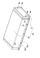
図1ないし図7の車両用のバッテリシステムは、複数の充電できる電池セル1を内蔵する複数のバッテリユニット3と、複数のバッテリユニット3を収納して固定してなる外装ケース30とを備える。図のバッテリシステムは、4組のバッテリユニット3を外装ケース30に収納して固定している。バッテリユニット3は、図8ないし図10に示すように、複数の電池セル1を積層してなる電池ブロック2と、この電池ブロック2の対向面にあって、積層された電池セル1を積層方向に挟着して固定してなる一対のエンドプレート4と、一対のエンドプレート4を連結してなる連結具5とを備える。
The vehicle battery system of FIGS. 1 to 7 includes a plurality of
電池セル1は角形電池セルで、正負の電極端子13を設けている電極面10を、図8ないし図10にあっては上面とし、互いに平行な姿勢で積層している。隣接する電池セル1の金属製の外装缶を絶縁するために、電池セル1の間に絶縁スペーサ15を挟着している。図の電池セル1は、電極面10の両端部に正負の電極端子13を設けて、中央部には、ガス排出弁11のガス排出口12を設けている。ガス排出口12から排出されるガスを外部に排気する中空状のガス排出ダクト6は、図2に示すように、電池ブロック2の電極面10の中央に積層方向に伸びるように配置されて、電池セル1のガス排出弁11から排出されるガスを外部に排出する。
The
電池セル1は、図10に示すように、厚さに比べて幅が広い、言い換えると幅よりも薄い角形電池セルで、厚さ方向に積層されて電池ブロック2としている。この電池セル1は、リチウムイオン二次電池である。ただし、電池セルは、ニッケル水素電池やニッケルカドミウム電池等の二次電池とすることもできる。図の電池セル1は、幅の広い両表面を四角形とする角形の電池セルで、両表面を対向するように積層して電池ブロック2としている。
As shown in FIG. 10, the
ガス排出弁11は、電池セル1の内圧が設定圧力よりも高くなると開弁して、内圧の上昇を防止する。このガス排出弁11は、ガス排出口12を閉塞する弁体(図示せず)を内蔵している。弁体は、設定圧力で破壊される薄膜、あるいは設定圧力で開弁するように弾性体で弁座に押圧されている弁である。ガス排出弁11が開弁されると、ガス排出口12を介して電池セル1の内部が外部に開放され、内部のガスを放出して内圧の上昇が防止される。
The
隣接する電池セル1は、正負の電極端子13を接続して互いに直列に接続される。図8と図9のバッテリシステムは、隣接する電池セル1の正負の電極端子13をバスバー14を介して互いに直列に接続している。バスバー14に連結される電極端子13は、止ネジ17とナット18を介して接続している。図のバッテリシステムは、電池セル1の電極端子13を電極面10に対して傾斜する姿勢としている。図の電極端子13は、電極面10に対して約45度傾斜する姿勢としている。この電池セル1は、下から止ネジ17を挿入しやすく、また、上からナット18をねじ込んで固定できる。隣接する電池セル1を互いに直列に接続するバッテリシステムは、出力電圧を高くして出力を大きくできる。ただし、バッテリシステムは、隣接する電池セルを並列に接続することもできる。
図8ないし図10に示す電池ブロック2は、積層している電池セル1の間に絶縁スペーサ15を挟着している。絶縁スペーサ15は、隣接する電池セル1を絶縁する。さらに、図10の絶縁スペーサ15は、隣接する電極端子13の間に突出する絶縁壁15Bを設けている。絶縁スペーサ15は、図5に示すように、両面に電池セル1を嵌着して定位置に配置する形状として、隣接する電池セル1を位置ずれしないように積層できる。絶縁スペーサ15で絶縁して積層される電池セル1は、外装缶をアルミニウムなどの金属製にできる。電池セル1の間に絶縁スペーサ15を挟着する構造は、絶縁スペーサ15をプラスチック等の熱伝導率の小さい材質で製作して、隣接する電池セル1の熱暴走を効果的に防止できる効果もある。ただ、電池ブロックは、電池セルの外装缶の表面を絶縁被膜で覆って絶縁することにより、絶縁スペーサを挟着することなく複数の電池セルを積層することもできる。この絶縁被膜には、プラスチック製の熱収縮チューブや絶縁塗料が使用できる。この電池ブロックは、電池セルの底面や上面を冷却パイプで冷却する構造として、電池セルを底面や上面から効率よく冷却できる。
In the
電池セル1に積層される絶縁スペーサ15は、電池セル1を効果的に冷却するために、電池セル1との間に、空気などの冷却気体を通過させる送風隙間16を設けている。図10の絶縁スペーサ15は、電池セル1との対向面に、両側縁まで延びる溝15Aを設けて、電池セル1との間に送風隙間16を設けている。図の絶縁スペーサ15は、複数の溝15Aを、互いに平行に所定の間隔で設けている。図の絶縁スペーサ15は、両面に溝15Aを設けており、互いに隣接する電池セル1と絶縁スペーサ15との間に送風隙間16を設けている。この構造は、絶縁スペーサ15の両側に形成される送風隙間16で、両側の電池セル1を効果的に冷却できる特長がある。ただ、絶縁スペーサは、片面にのみ溝を設けて、電池セルと絶縁スペーサとの間に送風隙間を設けることもできる。図の送風隙間16は、電池ブロック2の左右に開口するように水平方向に設けている。送風隙間16に強制送風される空気は、電池セル1の外装缶を直接に効率よく冷却する。この構造は、電池セル1の熱暴走を有効に阻止しながら、電池セル1を効率よく冷却できる特徴がある。
The insulating
バッテリユニット3は、電池セル1を積層してなる電池ブロック2の両端面を一対のエンドプレート4で挟着している。電池ブロック2の両端に配設している一対のエンドプレート4は互いに連結具5に連結されて、その間に電池ブロック2を挟着して固定している。
In the
エンドプレート4は、積層している角形の電池セル1の外形と同じ形状と寸法の四角形として、積層している電池ブロック2を両端面から挟着して固定している。エンドプレート4は、プラスチック製で、外側面には、縦横に伸びる補強リブを一体的に成形して設けて曲げ強度を向上できる。図8と図9のエンドプレート4は、プラスチックからなるエンドプレート4の本体部の外側面に補強金属8を積層して補強し、この補強金属8に連結具5を固定している。この構造は、エンドプレート4を補強金属8で補強して強固な構造にでき、また、連結具5を強固に連結できる特徴がある。ただ、エンドプレートは、必ずしも補強金属で補強する必要はない。
The
連結具5は、鉄や鉄合金などの金属製で、その両端部を止ネジ19でエンドプレート4に固定している。図8と図9のバッテリユニット3は、各々のエンドプレート4の四隅部に連結具5の端部を固定して、4本の連結具5で一対のエンドプレート4を連結している。連結具5は、電池セル1の積層方向に伸びるバインド部5Xの両端部に、L字状に折曲してなる固定部5Yを設けている。固定部5Yは、エンドプレート4の外側表面に沿うように折曲されて、止ネジ19を挿入する貫通孔を設けている。連結具5は、固定部5Yの貫通孔に止ネジ19を挿入し、この止ネジ19をエンドプレート4の補強金属8にねじ込んで一対のエンドプレート4を固定している。補強金属を設けないエンドプレートは、止ネジをエンドプレートにねじ込んで、連結具をエンドプレートに固定する。
The
図8と図9に示すバッテリユニット3は、連結具5B、5Cをパイプ状として、冷却気体を送風隙間16に強制送風するためのバイパスダクト20に併用している。バイパスダクト20に併用される連結具5B、5Cは、金属パイプの角パイプ50としている。この連結具5B、5Cは、電池セル1を冷却する気体や空気をバイパスして、全ての電池セル1を均一に冷却する。図2と図3に示すバッテリシステムは、2列に並べて配置しているバッテリブロック9の間と外側とに3列の送風ダクト33を設けて、バッテリユニット3の両側に送風ダクト33を設けている。バッテリユニット3の両側に設けられる送風ダクト33は、電池セル1の間に設けている送風隙間16に連結している。バッテリユニット3の両側に設けている送風ダクト33は、一方を供給ダクト33A、他方を排出ダクト33Bとしている。図3のバッテリシステムは、2列に配置しているバッテリブロック9の間に設けている送風ダクト33を供給ダクト33Aとして、バッテリブロック9の外側に設けている送風ダクト33を排出ダクト33Bとしている。このバッテリシステムは、供給ダクト33Aから送風隙間16に冷却気体を強制送風し、送風隙間16を通過した冷却気体を排出ダクト33Bから外部に排出して各々の電池セル1を冷却する。
The
図2と図3のバッテリシステムは、全てのバッテリユニット3を均一に冷却するために、連結具5B、5Cを角パイプ50の金属パイプとしてバイパスダクト20に併用している。図のバッテリシステムは、2組のバッテリユニット3を直線状に配置してバッテリブロック9としているので、一方のバッテリユニット3は冷却気体の上流側にあって、他方のバッテリユニット3は下流側に配置される。この図のバッテリシステムは、冷却気体の上流側に配置している2列のバッテリユニット3(図2と図3において左側のバッテリユニット3)の間に配設している連結具5Bを金属パイプの角パイプ50として、下流側のバッテリユニット3にバイパスして送風する。さらに、下流側のバッテリユニット3の両側に配設している連結具5Cを金属パイプの角パイプ50として、上流側のバッテリユニット3から排出される冷却気体をバイパスして外部に排気する。
In the battery system of FIGS. 2 and 3, the
以上のバッテリシステムは、上流側に配置している2列のバッテリユニット3の送風隙間16を通過した冷却気体の一部を、下流側のバッテリユニット3の外側の上下に固定している連結具5Cでバイパスして外部に排気する。上流側にあるバッテリユニット3の送風隙間16を通過して外部に排気される冷却気体は、下流側の排出ダクト33Bである送風ダクト33とバイパスダクト20である連結具5Cに分流して外部に排気されるので、下流側のバッテリユニット3の送風隙間16を通過した冷却気体の排気への影響を極減してスムーズに排出される。このバッテリシステムは、上流側のバッテリユニット3の送風隙間16を通過した冷却気体を下流側の排出ダクト33Bとバイパスダクト20である連結具5Cから排気して、下流側のバッテリユニット3の送風隙間16を通過した冷却気体を下流側の排出ダクト33Bから排気する。したがって、このバッテリシステムは、下流側のバッテリユニット3の外側に設けられて、バイパスダクト20に併用される連結具5Bの開口面積と、下流側のバッテリユニット3の外側において、上下の連結具5Bの間に設けている排出ダクト33Bとなる送風ダクト33の開口面積との比率を最適なように調整して、上流側と下流側のバッテリユニット3の排気を理想的なバランスにコントロールできる。
The above battery system is a connector that fixes a part of the cooling gas that has passed through the
さらに、下流側のバッテリユニット3は、上流側のバッテリユニット3の間に設けているバイパスダクト20に併用される連結具5Bを介して直接に冷却気体が供給される。したがって、下流側のバッテリユニット3は、上流側のバッテリユニット3の間の送風ダクト33である供給ダクト33Aを通過した冷却気体と、バイパスダクト20である連結具5Bでバイパスされた冷却気体が送風される。このバッテリシステムは、上流側のバッテリユニット3の間に設けられて、バイパスダクト20に併用される連結具5Bの開口面積と、上流側のバッテリユニット3の間において、上下の連結具5Bの間に設けている供給ダクト33Aとなる送風ダクト33の開口面積との比率を最適なように調整して、上流側と下流側のバッテリユニット3に強制送風する冷却気体の送風量をコントロールできる。したがって、上流側と下流側のバッテリユニット3を均一に冷却できるように、バイパスダクト20となる連結具5B、5Cの開口面積を調整することで、上流側と下流側のバッテリユニット3を均一に冷却できる。
Further, the cooling battery is directly supplied to the
以上のバッテリシステムは、上流側にあるバッテリユニット3の送風隙間16を通過した冷却気体を、下流側の排出ダクト33Bとバイパスダクト20である連結具5Cに分流して外部に排気するが、バッテリシステムは、図11に示すように、上流側にあるバッテリユニット3の送風隙間16を通過した冷却気体を、下流側の排出ダクト33Bに通過させることなく、下流側の連結具5Cをバイパスさせて外部に排気することもできる。このバッテリシステムは、図11の一部拡大図に示すように、下流側のバッテリユニット3の外側に設けられる排出ダクト33Bの上流側を閉塞プレート29で閉塞して実現できる。このバッテリシステムは、上流側にあるバッテリユニット3の送風隙間16を通過した冷却気体が、下流側の排出ダクト33Bに流入することなく連結具5Cを通過して外部に排気されるので、下流側のバッテリユニット3の送風隙間16を通過した冷却気体の排気に影響されずにスムーズに排出される。
In the battery system described above, the cooling gas that has passed through the
さらに、以上のバッテリシステムは、上流側のバッテリユニット3の間に設けた供給ダクト33Aを通過した冷却気体と、バイパスダクト20である連結具5Bでバイパスされた冷却気体の両方を、下流側にあるバッテリユニット3の間の供給ダクト33Aに送風しているが、バッテリシステムは、図12に示すように、上流側にあるバッテリユニット3の間の供給ダクト33Aを通過した冷却気体を下流側の供給ダクト33Aに流入させることなく、すなわち、上流側の上下の連結具5Bを通過した冷却気体のみを下流側の供給ダクト33Aに送風することもできる。このバッテリシステムは、図12の一部拡大図に示すように、上流側のバッテリユニット3の間に設けられる供給ダクト33Aの下流側を閉塞プレート28で閉塞して実現できる。このバッテリシステムは、上流側にあるバッテリユニット3と下流側にあるバッテリユニット3とに別々に冷却気体を送風するので、上流側と下流側のバッテリユニット3に強制送風する冷却気体の送風量を理想的にコントロールできる。
Further, the battery system described above allows both the cooling gas that has passed through the
バイパスダクト20に併用される連結具5B、5Cは、バインド部5Xを金属パイプの角パイプ50として、その両端に固定部5Yを設けている。2列のバッテリユニット3の間に配設されるバイパスダクト20に併用される連結具5Bは、図8に示すように、その両端を開口して、角パイプ50の両側の側壁を両側に折曲して固定部5Yを設けている。この連結具5Bは、両側の固定部5Yを2列に配置される両側のバッテリユニット3のエンドプレート4に固定する。この連結具5Bは、ひとつで、2列に隣接して配列する2組のバッテリユニット3のエンドプレート4に固定できる。さらに、この連結具5Bは、2列に隣接しているバッテリユニット3の間に挟まれるように配置することで、2列のバッテリユニット3の間隔を正確に特定できる。また、バッテリユニット3の外側に配設されるバイパスダクト20に併用される連結具5Cは、図9に示すように、その両端を開口して角パイプ50の一方の側壁を折曲して固定部5Yとして、この固定部5Yをバッテリユニット3のエンドプレート4に固定している。以上の構造の連結具5B、5Cは、バインド部5Xを金属パイプとすることで、バインド部5Xの曲げ強度を向上できる特徴がある。
The
以上のバッテリシステムは、連結具5B、5Cをバイパスダクト20に併用するが、本発明のバッテリシステムは、連結具を必ずしもバイパスダクトに併用する必要はない。図13のバッテリシステムは、2列に並べて配設してなるバッテリユニット3の間に配設している内側の連結具5Dのバインド部5Xを、底プレート53の両側に平行な側壁54のある溝型としている。両側の側壁54は、その両端部をエンドプレート4の外側面に沿うようにL字状に折曲して固定部5Yとしている。この連結具5Dは、両側の側壁54を外側であって反対側に折曲加工して、ふたつの固定部5Yを設けている。この構造の内側の連結具5Dも、前述した角パイプ50の連結具5Bと同じように、2列に隣接して配列する2組のバッテリユニット3のエンドプレート4に固定できる。さらに、内側の連結具5Dは、そのバインド部5Xに設けている2列の側壁54を、2列に隣接している各々のバッテリユニット3の電池ブロック2の対向表面に沿うように固定しているので、前述した角パイプ50の連結具5Bと同じように、2列のバッテリユニット3の間隔を正確に特定できる。また、この構造の連結具5Dは、金属板を溝型に加工してバインド部5Xとして、バインド部5Xの曲げ強度を向上できる。さらに、1本の連結具5Dを2列に隣接して配置している2組のバッテリユニット3に連結するので、1本の連結具5Dで2列に隣接する2組のバッテリユニット3を連結して固定できる。
The battery system described above uses the
溝型の連結具5Dは、溝の開口部を対向する姿勢として、エンドプレート4の上下に固定される。エンドプレート4の上部に固定される連結具5Dは、溝の開口部を下向きとして固定され、下部に固定される連結具5Dは、溝の開口部を上向きとして固定される。エンドプレート4の上部に固定している連結具5Dは、溝型の底プレート53を水平姿勢として電池セル1の上面とほぼ同一面に配置して、上面に補強パイプ7を固定している。エンドプレート4の下部に固定している連結具5Dは、底プレート53を水平姿勢として電池セル1の下面とほぼ同一面に配置して、外装ケース30の底板31Xに固定している。
The groove-
さらに、図2において、冷却気体の上流側に配置している2列のバッテリユニット3の外側に配設している連結具5Aと、下流側のバッテリユニット3の間に配設している連結具5Aは、バインド部5Xの横断面形状をL字状として、バッテリユニット3の外側面に沿う垂直プレート部51と水平プレート部52とを設けている。この構造の連結具5Aは、水平プレート部52に上カバー38を固定し、また、外装ケース30の底板に固定している。エンドプレート4の上部に固定している連結具5は、水平プレート部52を電池セル1の上面とほぼ同一面に配置してその上に上カバー38を固定している。エンドプレート4の下部に固定している連結具5Aは、水平プレート部52を電池セル1の底面とほぼ同一面として、外装ケース30の底板31Xに固定している。
Further, in FIG. 2, the
バッテリユニット3は、その両側に設けている下側の連結具5を外装ケース30の底板31Xに固定し、さらに、エンドプレート4を外装ケース30の底板31Xに固定して、強固に外装ケース30に固定している。ただし、バッテリユニットは、エンドプレートのみを外装ケースに固定し、あるいは連結具のみを外装ケースに固定することもできる。とくに、断面形状をL字状または溝型とし、あるいは角パイプからなる金属製の連結具5は、優れた曲げ強度を有するので、これを外装ケース30に固定して、バッテリユニット3を強固に外装ケース30に固定できる。連結具5は、ボルト21とナット22を介して、補強パイプ7と上カバー38と底板31Xに固定される。ただし、連結具は、止ネジを介して補強パイプや上カバーや底板に固定することもできる。さらに、エンドプレート4は、ボルト36とナット37を介して下ケース31の底板31Xに固定している。ボルト36は、エンドプレート4を上下に貫通して、下ケース31の底板31Xの下面に設けたナット37にねじ込まれて、バッテリユニット3を外装ケース30に固定している。
The
2列に配置しているバッテリブロック9は、その間に補強パイプ7を固定している。補強パイプ7は金属パイプの角パイプである。図4と図5の断面図に示す補強パイプ7は、エンドプレート4の上側に固定している連結具5の横幅よりも、例えば1mmないし2cm幅広の角パイプである。図2、図4、及び図5の断面図に示すバッテリユニット3は、電池セル1の電極端子を電極カバー23でカバーしている。補強パイプ7は、この電極カバー23に当たらない幅としている。補強パイプ7は、複数組の、図2にあっては2組のバッテリユニット3を直線状に配置して、その耐振動特性、とくに曲げ強度を向上するものであるから、1本の金属パイプを互いに隣接して配置している2列のバッテリブロック9を構成する全てのバッテリユニット3に固定している。図4ないし図6のバッテリシステムは、補強パイプ7をバッテリユニット3の連結具5に固定している。角パイプの補強パイプ7は、上側の連結具5の上面に密着するように固定して、曲げ強度や耐振動特性を向上できる。補強パイプ7は、L字状の連結具5Aの水平プレート部52に固定し、あるいは、角パイプ50である連結具5Bの上面に固定し、あるいはまた、溝型の連結具5Dの底プレート53に固定される。ただ、補強パイプは、必ずしも角パイプとする必要はなく、たとえば、横断面形状を楕円形や四角形でない多角形とすることもできる。
The battery blocks 9 arranged in two rows have a reinforcing
補強パイプ7は、上側の連結具5にボルト21とナット22を介して固定している。すなわち、ボルト21が補強パイプ7と上側の連結具5を貫通し、その先端をナット22にねじ込んで固定している。ボルト21を挿入するために、補強パイプ7はボルト21をねじ込むボルト孔の上方に、ボルト21を通過させる貫通孔7Aを設けている。この構造は、補強パイプ7に上からボルト21を挿入し、このボルト21を補強パイプ7の底面と連結具5に貫通し、その先端にナット22をねじ込んで連結具5に固定される。ナット22は、連結具5の内面に溶接などの方法で固定している。この構造は、ボルト21をナット22にねじ込んで、補強パイプ7を連結具5に確実に固定できる。
The reinforcing
図2ないし図7のバッテリシステムは、4組のバッテリユニット3を外装ケース30に固定している。図のバッテリシステムは、2組のバッテリユニット3を直線状に配置してバッテリブロック9としている。図2のバッテリブロック9は、2組のバッテリユニット3を直線状に並べて直列配置してなる直列配置方向の長さを、バッテリユニット3の横幅より長くしている。さらに、バッテリシステムは、2組のバッテリブロック9を2列に配置して外装ケース30に固定している。このバッテリシステムは、2組のバッテリユニット3を直列に配置して1列のバッテリブロック9とし、さらに、2組のバッテリユニット3を備えるバッテリブロック9を2列に配置して、4組のバッテリユニット3を外装ケース30に収納して固定している。
2 to 7, four
図の外装ケース30は、下ケース31と上ケース32とで構成している。下ケース31と上ケース32は、溝型に加工された金属プレートである。下ケース31と上ケース32は、同じ厚さの金属プレートで製作され、あるいは下ケースを上ケースよりも厚い金属プレートで製作する。下ケース31は、底板31Xの両側に上方に伸びる側壁31Aを設けて溝型としている。上ケース32は、天板32Xの両側に下方に伸びる側壁32Aを設けて溝型としている。上ケース32の側壁32Aは、下ケース31の側壁31Aよりも高く成形している。図3のバッテリシステムは、下ケース31と上ケース32の横幅を等しくして、下ケース31の側壁32Aと上ケース32の側壁31Aとを互いに連結している。下ケース31と上ケース32は、複数のバッテリユニット3を直線状に配置してなる方向に伸びる両側の側壁31A、32Aを連結して、内部に複数列にバッテリユニット3を収納している。下ケース31と上ケース32は、互いに固定する先端縁に、外側に折曲された折曲片31a、32aを設けている。外装ケース30は、折曲片31a、32aを貫通する止ネジ34とナット35で折曲片31aと折曲片32aを固定し、あるいは折曲片を貫通するリベットなどで固定して、下ケース31と上ケース32とを連結している。下ケース31に固定される上ケース32は、天板32Xとバッテリユニット3との間に収納隙間を設けて、補強パイプ7をこの収納隙間に配設して、隣接するバッテリユニット3の上縁に固定している。
The illustrated
さらに、下ケース31と上ケース32からなる外装ケース30は、2列のバッテリブロック9の外側に送風ダクト33ができるように幅を広くしている。図3ないし図4のバッテリシステムは、2列に配置しているバッテリブロック9の中間に送風ダクト33を設け、さらにバッテリブロック9の外側であって側壁31A、32Aとの間にも送風ダクト33を設けている。2列のバッテリブロック9の間に設けている送風ダクト33は、上方を補強パイプ7で閉塞して、下方の開口部を下ケース31で閉塞している。2列のバッテリブロック9の外側に設けている送風ダクト33は、上方を上カバー38で閉塞して、下方を下ケース31で閉塞している。
Further, the
1…電池セル
2…電池ブロック
3…バッテリユニット
4…エンドプレート
5…連結具 5A…連結具
5B…連結具
5C…連結具
5D…連結具
5X…バインド部
5Y…固定部
6…ガス排出ダクト
7…補強パイプ 7A…貫通孔
8…補強金属
9…バッテリブロック
10…電極面
11…ガス排出弁
12…ガス排出口
13…電極端子
14…バスバー
15…絶縁スペーサ 15A…溝
15B…絶縁壁
16…送風隙間
17…止ネジ
18…ナット
19…止ネジ
20…バイパスダクト
21…ボルト
22…ナット
23…電極カバー
28…閉塞プレート
29…閉塞プレート
30…外装ケース
31…下ケース 31A…側壁
31a…折曲片
31X…底板
32…上ケース 32A…側壁
32a…折曲片
32X…天板
33…送風ダクト 33A…供給ダクト
33B…排出ダクト
34…止ネジ
35…ナット
36…止ネジ
37…ナット
38…上カバー
50…角パイプ
51…垂直プレート部
52…水平プレート部
53…底プレート
54…側壁
DESCRIPTION OF
5B ... Connector
5C ... Connector
5D ... Connector
5X ... Binding part
5Y:
15B ... Insulating
31a ... Folded piece
31X ...
32a ... bent piece
32X ...
33B ...
Claims (8)
前記複数のバッテリユニット(3)を直線状に並べてなるバッテリブロック(9)を複数列に並べて外装ケース(30)に固定しており、さらに、隣接するバッテリブロック(9)の間には補強パイプ(7)を配設して、この補強パイプ(7)を両側に配設されるバッテリブロック(9)を構成する各々のバッテリユニット(3)の上部に固定してなる車両用のバッテリシステム。 A vehicle battery system comprising a plurality of battery units (3) containing a plurality of rechargeable battery cells (1), and an exterior case (30) formed by housing and fixing the plurality of battery units (3). There,
The battery blocks (9) in which the plurality of battery units (3) are arranged in a straight line are arranged in a plurality of rows and fixed to the outer case (30), and a reinforcing pipe is provided between adjacent battery blocks (9). A vehicle battery system in which (7) is disposed and the reinforcing pipe (7) is fixed to the upper part of each battery unit (3) constituting the battery block (9) disposed on both sides.
Priority Applications (1)
| Application Number | Priority Date | Filing Date | Title |
|---|---|---|---|
| JP2009096528A JP2010250984A (en) | 2009-04-10 | 2009-04-10 | Battery system for vehicle |
Applications Claiming Priority (1)
| Application Number | Priority Date | Filing Date | Title |
|---|---|---|---|
| JP2009096528A JP2010250984A (en) | 2009-04-10 | 2009-04-10 | Battery system for vehicle |
Publications (1)
| Publication Number | Publication Date |
|---|---|
| JP2010250984A true JP2010250984A (en) | 2010-11-04 |
Family
ID=43313112
Family Applications (1)
| Application Number | Title | Priority Date | Filing Date |
|---|---|---|---|
| JP2009096528A Pending JP2010250984A (en) | 2009-04-10 | 2009-04-10 | Battery system for vehicle |
Country Status (1)
| Country | Link |
|---|---|
| JP (1) | JP2010250984A (en) |
Cited By (20)
| Publication number | Priority date | Publication date | Assignee | Title |
|---|---|---|---|---|
| KR20140042668A (en) * | 2012-09-28 | 2014-04-07 | 가부시키가이샤 리튬 에너지 재팬 | Electric storage device |
| WO2015126209A1 (en) * | 2014-02-24 | 2015-08-27 | 엘지전자 주식회사 | Battery pack |
| WO2016027377A1 (en) * | 2014-08-22 | 2016-02-25 | 日立オートモティブシステムズ株式会社 | On-board battery pack |
| JP2016072230A (en) * | 2014-09-30 | 2016-05-09 | 株式会社Gsユアサ | Power storage device |
| JP2017117640A (en) * | 2015-12-24 | 2017-06-29 | トヨタ自動車株式会社 | Battery pack for vehicle mounting |
| US10023039B2 (en) | 2016-02-25 | 2018-07-17 | Kubota Corporation | Work vehicle with a power-travel drive unit |
| WO2018198458A1 (en) * | 2017-04-28 | 2018-11-01 | 日立オートモティブシステムズ株式会社 | Battery pack |
| CN112262495A (en) * | 2018-06-12 | 2021-01-22 | 米巴电动汽车有限公司 | Electric storage device |
| JP2021064529A (en) * | 2019-10-15 | 2021-04-22 | トヨタ自動車株式会社 | Battery pack |
| CN115241593A (en) * | 2021-01-15 | 2022-10-25 | 张木念 | Unmanned aerial vehicle battery compartment convenient to change |
| JP2023509197A (en) * | 2020-09-30 | 2023-03-07 | 寧徳時代新能源科技股▲分▼有限公司 | BATTERY, APPARATUS, BATTERY MANUFACTURING METHOD AND MANUFACTURING APPARATUS |
| JP2023511310A (en) * | 2020-01-23 | 2023-03-17 | ブレン-トロニクス,インコーポレイテッド | Bulletproof case for rechargeable batteries |
| JP2023184096A (en) * | 2022-06-17 | 2023-12-28 | プライムアースEvエナジー株式会社 | Battery pack and battery pack case |
| US11901555B2 (en) | 2021-07-30 | 2024-02-13 | Contemporary Amperex Technology Co., Limited | Battery module, battery pack, and electric apparatus |
| US11990592B2 (en) | 2020-11-17 | 2024-05-21 | Contemporary Amperex Technology Co., Limited | Battery, apparatus using battery, and manufacturing method and manufacturing device of battery |
| US12002984B2 (en) | 2020-09-30 | 2024-06-04 | Contemporary Amperex Technology Co., Limited | Battery, apparatus, and preparation method and preparation apparatus of battery |
| US12068468B2 (en) | 2020-12-24 | 2024-08-20 | Contemporary Amperex Technology Co., Limited | Battery module and manufacturing method and device thereof, battery pack, and power consumption apparatus |
| US12113162B2 (en) | 2020-04-30 | 2024-10-08 | Contemporary Amperex Technology Co., Limited | Battery comprising first-type battery cell group and second-type battery cell group which are connected in series, apparatus, and method and device for manufacturing battery |
| US12132217B2 (en) | 2020-07-29 | 2024-10-29 | Contemporary Amperex Technology Co., Limited | Battery module, battery pack, apparatus, and method and device for manufacturing battery module |
| US12176509B2 (en) | 2020-09-30 | 2024-12-24 | Contemporary Amperex Technology (Hong Kong) Limited | Battery, apparatus, and preparation method and preparation apparatus of battery |
-
2009
- 2009-04-10 JP JP2009096528A patent/JP2010250984A/en active Pending
Cited By (36)
| Publication number | Priority date | Publication date | Assignee | Title |
|---|---|---|---|---|
| JP2014072087A (en) * | 2012-09-28 | 2014-04-21 | Lithium Energy Japan:Kk | Power storage device |
| US9252406B2 (en) | 2012-09-28 | 2016-02-02 | Gs Yuasa International Ltd. | Electric storage apparatus |
| KR20140042668A (en) * | 2012-09-28 | 2014-04-07 | 가부시키가이샤 리튬 에너지 재팬 | Electric storage device |
| US9515306B2 (en) | 2012-09-28 | 2016-12-06 | Gs Yuasa International Ltd. | Electric storage apparatus |
| KR102134737B1 (en) * | 2012-09-28 | 2020-07-16 | 가부시키가이샤 지에스 유아사 | Electric storage device |
| WO2015126209A1 (en) * | 2014-02-24 | 2015-08-27 | 엘지전자 주식회사 | Battery pack |
| KR20150099965A (en) | 2014-02-24 | 2015-09-02 | 엘지전자 주식회사 | Battery Pack |
| KR101649154B1 (en) * | 2014-02-24 | 2016-08-18 | 엘지전자 주식회사 | Battery Pack |
| US10665915B2 (en) | 2014-02-24 | 2020-05-26 | Lg Electronics Inc. | Battery pack |
| US10305076B2 (en) | 2014-08-22 | 2019-05-28 | Hitachi Automotive Systems, Ltd. | On-vehicle battery pack |
| WO2016027377A1 (en) * | 2014-08-22 | 2016-02-25 | 日立オートモティブシステムズ株式会社 | On-board battery pack |
| JP2016072230A (en) * | 2014-09-30 | 2016-05-09 | 株式会社Gsユアサ | Power storage device |
| JP2017117640A (en) * | 2015-12-24 | 2017-06-29 | トヨタ自動車株式会社 | Battery pack for vehicle mounting |
| US10023039B2 (en) | 2016-02-25 | 2018-07-17 | Kubota Corporation | Work vehicle with a power-travel drive unit |
| WO2018198458A1 (en) * | 2017-04-28 | 2018-11-01 | 日立オートモティブシステムズ株式会社 | Battery pack |
| JPWO2018198458A1 (en) * | 2017-04-28 | 2020-03-05 | 日立オートモティブシステムズ株式会社 | Battery pack |
| CN112262495A (en) * | 2018-06-12 | 2021-01-22 | 米巴电动汽车有限公司 | Electric storage device |
| US11735784B2 (en) | 2018-06-12 | 2023-08-22 | Audi Aktiengesellschaft | Rechargeable battery |
| JP2021064529A (en) * | 2019-10-15 | 2021-04-22 | トヨタ自動車株式会社 | Battery pack |
| JP7243561B2 (en) | 2019-10-15 | 2023-03-22 | トヨタ自動車株式会社 | battery pack |
| JP2023511310A (en) * | 2020-01-23 | 2023-03-17 | ブレン-トロニクス,インコーポレイテッド | Bulletproof case for rechargeable batteries |
| US12272780B2 (en) | 2020-04-30 | 2025-04-08 | Contemporary Amperex Technology Co., Limited | Battery module, apparatus, battery pack, and method and device for manufacturing battery module |
| US12113162B2 (en) | 2020-04-30 | 2024-10-08 | Contemporary Amperex Technology Co., Limited | Battery comprising first-type battery cell group and second-type battery cell group which are connected in series, apparatus, and method and device for manufacturing battery |
| US12132217B2 (en) | 2020-07-29 | 2024-10-29 | Contemporary Amperex Technology Co., Limited | Battery module, battery pack, apparatus, and method and device for manufacturing battery module |
| US12002984B2 (en) | 2020-09-30 | 2024-06-04 | Contemporary Amperex Technology Co., Limited | Battery, apparatus, and preparation method and preparation apparatus of battery |
| US12034176B2 (en) | 2020-09-30 | 2024-07-09 | Contemporary Amperex Technology Co., Limited | Battery, apparatus, and preparation method and preparation apparatus of battery |
| JP7569481B2 (en) | 2020-09-30 | 2024-10-18 | 香港時代新能源科技有限公司 | Battery, device, battery manufacturing method and manufacturing device |
| JP2023509197A (en) * | 2020-09-30 | 2023-03-07 | 寧徳時代新能源科技股▲分▼有限公司 | BATTERY, APPARATUS, BATTERY MANUFACTURING METHOD AND MANUFACTURING APPARATUS |
| US12176509B2 (en) | 2020-09-30 | 2024-12-24 | Contemporary Amperex Technology (Hong Kong) Limited | Battery, apparatus, and preparation method and preparation apparatus of battery |
| US11990592B2 (en) | 2020-11-17 | 2024-05-21 | Contemporary Amperex Technology Co., Limited | Battery, apparatus using battery, and manufacturing method and manufacturing device of battery |
| US12068468B2 (en) | 2020-12-24 | 2024-08-20 | Contemporary Amperex Technology Co., Limited | Battery module and manufacturing method and device thereof, battery pack, and power consumption apparatus |
| CN115241593B (en) * | 2021-01-15 | 2024-05-24 | 深圳市九方电子科技有限公司 | Unmanned aerial vehicle motor Chi Cang convenient to change |
| CN115241593A (en) * | 2021-01-15 | 2022-10-25 | 张木念 | Unmanned aerial vehicle battery compartment convenient to change |
| US11901555B2 (en) | 2021-07-30 | 2024-02-13 | Contemporary Amperex Technology Co., Limited | Battery module, battery pack, and electric apparatus |
| JP2023184096A (en) * | 2022-06-17 | 2023-12-28 | プライムアースEvエナジー株式会社 | Battery pack and battery pack case |
| JP7787778B2 (en) | 2022-06-17 | 2025-12-17 | トヨタバッテリー株式会社 | Battery packs and battery pack cases |
Similar Documents
| Publication | Publication Date | Title |
|---|---|---|
| JP2010250984A (en) | Battery system for vehicle | |
| CN114512758B (en) | Single battery, power battery pack and electric vehicle | |
| US8507122B2 (en) | Power supply device including a plurality of battery cells arranged side by side | |
| JP7596043B2 (en) | Power supply device, electric vehicle using the same, and power storage device | |
| CN107210397B (en) | Power supply unit and vehicle having power supply unit | |
| JP5183171B2 (en) | Battery system | |
| EP3136497B1 (en) | Battery module including water cooling structure | |
| JP5518386B2 (en) | Battery system | |
| JP5288971B2 (en) | Battery system | |
| EP2631985B1 (en) | Battery pack having excellent cooling efficiency | |
| KR101218751B1 (en) | Middle or Large-sized Battery Pack of Improved Cooling Efficiency | |
| US20110111273A1 (en) | Vehicle power supply device and method for producing vehicle power supply device | |
| CN216720173U (en) | Battery box, battery and power consumption device | |
| US20120141855A1 (en) | Battery pack for suppressing deviation of central battery cell and vehicle including the same | |
| US20100297486A1 (en) | Battery system | |
| US9112249B2 (en) | Power source apparatus having cooling path and gas discharge path | |
| CN103703585B (en) | There is the electrochemical cell of improved heat collection and transmission system | |
| US12237532B2 (en) | Power supply device, and vehicle and electrical storage device each equipped with same | |
| KR20160040799A (en) | A Battery Pack Case Having Efficient Cooling Structure | |
| CN118104043A (en) | Battery cell pack for electric vehicle | |
| JP2010272378A (en) | Battery system for vehicle | |
| WO2018235557A1 (en) | POWER SUPPLY DEVICE, VEHICLE HAVING THE SAME, AND STORAGE DEVICE | |
| WO2014010437A1 (en) | Power source device and vehicle provided with said power source device | |
| WO2021157139A1 (en) | Power supply device, electric vehicle using same, and power storage device | |
| KR20130084722A (en) | Battery pack of novel air cooling structure |