JP2010204397A - Video display device and head-mounted display - Google Patents
Video display device and head-mounted display Download PDFInfo
- Publication number
- JP2010204397A JP2010204397A JP2009050076A JP2009050076A JP2010204397A JP 2010204397 A JP2010204397 A JP 2010204397A JP 2009050076 A JP2009050076 A JP 2009050076A JP 2009050076 A JP2009050076 A JP 2009050076A JP 2010204397 A JP2010204397 A JP 2010204397A
- Authority
- JP
- Japan
- Prior art keywords
- hoe
- image
- light
- incident
- light guide
- Prior art date
- Legal status (The legal status is an assumption and is not a legal conclusion. Google has not performed a legal analysis and makes no representation as to the accuracy of the status listed.)
- Withdrawn
Links
Images

Landscapes
- Diffracting Gratings Or Hologram Optical Elements (AREA)
Abstract
Description
本発明は、ユーザの頭部に装着される映像表示機器であり、表示素子の画像をホログラフィック光学素子(Holographic Optical Element、以下、「HOE」と記す。)を用いて使用者の瞳に導くヘッドマウントディスプレイ(Head Mounted Display、以下、「HMD」と記す。)、および該ヘッドマウントディスプレイを構成する映像表示装置に関連し、詳しくは、HOEの記録層の熱収縮に起因する回折角の変化率の影響を軽減するのに好適な映像表示装置およびHMDに関する。 The present invention is a video display device worn on a user's head, and guides an image of the display element to a user's pupil using a holographic optical element (hereinafter referred to as “HOE”). A head mounted display (hereinafter referred to as “HMD”) and a video display device constituting the head mounted display, and more specifically, a change in diffraction angle caused by thermal contraction of the recording layer of the HOE The present invention relates to a video display device and an HMD suitable for reducing the influence of the rate.
近年、ユーザの頭部に装着される映像表示機器であるHMDが一般に知られている。HMDは、液晶表示パネル等の表示素子上に表示された画像を光学的に拡大し、拡大された虚像として使用者に観察させるように構成されている。このようなHMDには、使用者の眼前に支持される導光板に入射された表示素子からの画像の光を反射、回折させて使用者の瞳に効率良く導くため、HOEが備えられている。この種のHMDの一例が特許文献1に開示されている。
In recent years, an HMD that is a video display device mounted on a user's head is generally known. The HMD is configured to optically enlarge an image displayed on a display element such as a liquid crystal display panel and allow a user to observe it as an enlarged virtual image. Such an HMD is equipped with a HOE for efficiently guiding the image light from the display element incident on the light guide plate supported in front of the user's eyes to the user's pupil by reflecting and diffracting it. . An example of this type of HMD is disclosed in
特許文献1に記載のHOEには、ホログラム用感光材料としてフォトポリマーが使用されている。特許文献1の図5においては、HOEに入射された入射光に対する射出光のバランス(例えば物体光と参照光の単位面積当たりの強度バランスや、トレードオフ関係にある回折角度と導光部材の厚みとの設定バランスなど)や製造容易性などを考慮して、回折角が45(deg)付近になるように反射型HOEが作製されている。具体的には、反射型HOEのフォトポリマー層に、互いに角度をなす同一波長の2光束を入射させて干渉させる。このとき干渉により生じた光強度の空間分布に従いモノマーが重合してフォトポリマーが凝集する。これにより、当該波長に対応するピッチを有すると同時にフォトポリマー層の入射面(又は射出面)に対して角度をなす干渉縞が、屈折率格子としてフォトポリマー層に形成されることとなる。
In the HOE described in
しかし、実際には、反射型HOEの作製の際にモノマーの重合反応を促進させるためベーキング処理を行ったとき、フォトポリマーが熱収縮する。干渉縞が例えばフォトポリマー層の膜厚方向に並ぶように記録されている場合には、該膜厚方向の収縮により干渉縞のピッチが狭くなることが知られている。本出願人は、かかる点に着目して、特許文献1に記載の反射型HOEのように干渉縞がフォトポリマー層の入射面に対して角度をなすように記録される場合には、フォトポリマーの熱収縮により干渉縞のピッチが狭くなる以外にも該角度が変化することを発見した。
However, in actuality, when a baking process is performed in order to promote the polymerization reaction of the monomer during the production of the reflective HOE, the photopolymer shrinks thermally. For example, when the interference fringes are recorded so as to be arranged in the film thickness direction of the photopolymer layer, it is known that the pitch of the interference fringes becomes narrow due to the contraction in the film thickness direction. The present applicant pays attention to this point, and when the interference fringes are recorded so as to form an angle with respect to the incident surface of the photopolymer layer as in the reflection type HOE described in
フォトポリマー層の入射面に対して干渉縞がなす角度が熱収縮により変化した場合、反射型HOEに入射された入射光の回折角は、本来想定している設計上の角度からずれてしまう。そのため、表示素子の画像が意図した位置に、つまり使用者の瞳に効率良く導かれない弊害が生じる。反射型HOEのような小型精密光学機器は誤差に対する許容度が低いため、意図しない回折角の僅かなズレが画像性能を大きく劣化させる虞がある。 When the angle formed by the interference fringes with respect to the incident surface of the photopolymer layer changes due to thermal contraction, the diffraction angle of the incident light incident on the reflective HOE deviates from the originally designed angle. For this reason, there is a problem that the image of the display element is not efficiently guided to the intended position, that is, to the user's pupil. A small precision optical instrument such as a reflective HOE has a low tolerance for errors, so that a slight deviation of an unintended diffraction angle may greatly deteriorate image performance.
本発明は上記の事情に鑑みてなされたものであり、その目的とするところは、フォトポリマーの熱収縮に起因して回折角が変化したときの影響を軽減するのに好適な映像表示装置、およびHMDを提供することにある。 The present invention has been made in view of the above circumstances, and its object is to provide a video display device suitable for reducing the influence when the diffraction angle changes due to thermal shrinkage of a photopolymer, And providing an HMD.
上記の課題を解決する本発明の一形態に係る映像表示装置は、画像を表示する表示素子と、表示素子に表示された画像が入射される導光部材と、導光部材に入射された画像を該導光部材内部で全反射させて所定位置に伝搬されるように回折する第一のHOEと、所定位置に伝搬された画像を使用者の瞳に向かって回折する第二のHOEとを有しており、以下の特徴を持つ。すなわち、かかる映像表示装置が有する第一又は第二のHOEは透過型又は反射型HOEであり、該第一又は第二のHOEの記録層の熱収縮による回折角の変化の割合が所定の割合以下に収まるように、該第一又は第二のHOEによる設計上の回折角が所定角度以上であることを特徴としている。 A video display device according to an embodiment of the present invention that solves the above problems includes a display element that displays an image, a light guide member that receives an image displayed on the display element, and an image that enters the light guide member. A first HOE that diffracts the light so that it is totally reflected inside the light guide member and propagates to a predetermined position, and a second HOE that diffracts the image propagated to the predetermined position toward the pupil of the user. It has the following characteristics. That is, the first or second HOE included in the video display device is a transmission type or a reflection type HOE, and the rate of change of the diffraction angle due to the thermal contraction of the recording layer of the first or second HOE is a predetermined rate. The design diffraction angle by the first or second HOE is equal to or greater than a predetermined angle so as to fit in the following.
各HOEによる回折角を所定角度以上に設定することにより、フォトポリマーの熱収縮に起因した回折角の変化率、つまり回折角誤差が簡易に抑えられる。そのため、表示素子の画像を意図した位置に、つまり使用者の瞳に効率良く導かれるようになる。また、回折角を所定角度以上とし大きな角度に設定するほど、導光部材内部における画像の各反射ポイントが離れる。そのため、導光部材を薄型化させた場合であっても隣接する反射ポイントが重ならない設計が可能である。導光部材の薄型化により映像表示装置の軽量化が達成される。また、回折角を所定角度以上とし大きな角度に設定することにより、導光部材内部を伝搬される画像光の反射回数を削減することができる。反射回数の削減により導光部材内部を伝搬される画像光の光路が短くなるため、内部拡散による光量損失が低減する。このため使用者は低損失の明るい画像を観察することができる。 By setting the diffraction angle by each HOE to be equal to or larger than a predetermined angle, the change rate of the diffraction angle caused by the thermal shrinkage of the photopolymer, that is, the diffraction angle error can be easily suppressed. Therefore, the image of the display element is efficiently guided to the intended position, that is, the user's pupil. Further, as the diffraction angle is set to a predetermined angle or larger and set to a larger angle, the reflection points of the image in the light guide member are separated. Therefore, even when the light guide member is thinned, a design in which adjacent reflection points do not overlap is possible. The weight of the image display device can be reduced by reducing the thickness of the light guide member. Further, by setting the diffraction angle to a predetermined angle or larger and setting it to a large angle, it is possible to reduce the number of times the image light is propagated through the light guide member. Since the optical path of the image light propagating through the light guide member is shortened by reducing the number of reflections, the light quantity loss due to internal diffusion is reduced. For this reason, the user can observe a bright image with low loss.
ここで、本発明に係る映像表示装置は、第一又は第二のHOEの記録層の熱収縮率をα(単位:%)と定義し、該第一又は第二のHOEによる設計上の回折角をθa(単位:deg)と定義した場合に、次の条件(1)、(2)
1<α<5 ・・・(1)
60≦θa ・・・(2)
を満たす構成であることが望ましい。かかる構成によれば、回折角の変化率を例えば2.5%以下といった極めて低い水準に抑えることができる。
Here, in the video display device according to the present invention, the thermal contraction rate of the recording layer of the first or second HOE is defined as α (unit:%), and the design cycle by the first or second HOE is defined. When the folding angle is defined as θa (unit: deg), the following conditions (1), (2)
1 <α <5 (1)
60 ≦ θa (2)
It is desirable that the configuration satisfies the above. According to such a configuration, the change rate of the diffraction angle can be suppressed to an extremely low level such as 2.5% or less.
また、上記の課題を解決する本発明の別の形態の映像表示装置は、画像を表示する表示素子と、表示素子に表示された画像が入射される導光部材と、導光部材に入射された画像を該導光部材内部で全反射させて所定位置に伝搬されるように回折する第一のHOEと、所定位置に伝搬された画像を使用者の瞳に向かって回折する第二のHOEとを有しており、以下の特徴を持つ。すなわち、かかる映像表示装置が有する第一又は第二のHOEは透過型又は反射型HOEであり、該第一又は第二のHOEの記録層の熱収縮による回折角の変化の割合が所定の割合以下に収まるように、該第一又は第二のHOEの入射端面と該記録層に記録される干渉縞の方向とがなす設計上の角度が所定角度以上であることを特徴としている。 In addition, a video display device according to another aspect of the present invention that solves the above problems includes a display element that displays an image, a light guide member that receives an image displayed on the display element, and a light incident on the light guide member. The first HOE that diffracts the reflected image so that it is totally reflected inside the light guide member and propagates to a predetermined position, and the second HOE that diffracts the image propagated to the predetermined position toward the pupil of the user And has the following characteristics. That is, the first or second HOE included in the video display device is a transmission type or a reflection type HOE, and the rate of change of the diffraction angle due to the thermal contraction of the recording layer of the first or second HOE is a predetermined rate. The design angle formed by the incident end face of the first or second HOE and the direction of the interference fringes recorded on the recording layer is equal to or greater than a predetermined angle so as to be contained below.
上記構成の映像表示装置においては、第一又は第二のHOEの記録層の熱収縮率をα(単位:%)と定義し、該第一又は第二のHOEの入射端面と該記録層に記録される干渉縞の方向とがなす設計上の角度をθb(単位:deg)と定義した場合に、次の条件(3)、(4)
1<α<5 ・・・(3)
30≦θb ・・・(4)
を満たすことが好ましい。
In the video display device having the above configuration, the thermal contraction rate of the recording layer of the first or second HOE is defined as α (unit:%), and the incident end face of the first or second HOE and the recording layer When the design angle formed by the direction of the interference fringes to be recorded is defined as θb (unit: deg), the following conditions (3), (4)
1 <α <5 (3)
30 ≦ θb (4)
It is preferable to satisfy.
第一又は第二のHOEの記録層は第一面と該第一面の裏面である第二面とを有しており、HOEの干渉縞は、例えば第一面側から記録層に入射された第一の光束と、該第一の光束と120(単位:deg)以下の角度をなし、第二面側から該記録層に入射された第二の光束とが該記録層内で干渉することにより該記録層に記録されたものである。 The recording layer of the first or second HOE has a first surface and a second surface which is the back surface of the first surface, and the interference fringes of the HOE are incident on the recording layer from the first surface side, for example. The first light beam and the first light beam form an angle of 120 (unit: deg) or less, and the second light beam incident on the recording layer from the second surface side interferes in the recording layer. This is recorded on the recording layer.
また、上記の課題を解決する本発明の一形態に係るHMDは、第二のHOEからの画像を虚像として使用者に観察させるように、上記の何れかに記載の映像表示装置を該使用者の眼前で支持する支持手段を有したことを特徴としている。 In addition, the HMD according to an embodiment of the present invention that solves the above-described problems provides the video display device according to any one of the above to the user so that the user can observe the image from the second HOE as a virtual image. It has the support means to support in front of the eyes.
本発明に係る映像表示装置およびHMDによれば、フォトポリマーの熱収縮に起因する回折角誤差が良好に抑えられる。そのため、表示素子の画像を使用者の瞳に高い利用効率で導くことが可能である。 According to the video display device and the HMD according to the present invention, the diffraction angle error due to the thermal shrinkage of the photopolymer can be satisfactorily suppressed. Therefore, it is possible to guide the image of the display element to the user's pupil with high utilization efficiency.
以下、図面を参照して、本発明の実施形態について説明する。 Embodiments of the present invention will be described below with reference to the drawings.
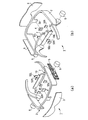
図1(a)、図1(b)はそれぞれ、本実施形態のHMD1の構成を示す正面側斜視図、背面側斜視図である。図1(a)及び図1(b)に示されるように、使用者の頭部に装着される眼鏡型フレーム2の正面部には、眼鏡レンズ3が取り付けられる。眼鏡型フレーム2の取付部2aには、画像を照明するためのバックライト4が取り付けられる。眼鏡型フレーム2のツル部分には、画像を映し出すための信号処理機器5、及び音声を再生するスピーカー6が設けられている。表示素子ユニット(例えば液晶表示素子)20は、信号処理機器5の回路に接続された配線と一体化されたアーム7により、使用者の両眼中央に位置し、かつバックライト4の光軸線上に表示素子ユニット20の略中心部が配置するように保持される。更に、表示素子ユニット20は、光学部材(例えばSF11)からなる導光板10の略中央部に位置するように、導光板10に対して相対的に固定される。導光板10は、アーム7により、使用者の眼前に位置するように支持される。導光板10の第一面10aの略中央には表示素子ユニット20が、使用者の眼前に位置する箇所にはHOE32R、32Lが、それぞれ接着等により第一面10a上に密着固定されている。
FIG. 1A and FIG. 1B are a front perspective view and a rear perspective view, respectively, showing the configuration of the
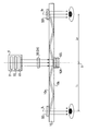
図2は、本実施形態のHMD1の構成を模式的に示す側面図である。なお、図2においては、図面を明瞭化するため、発明の主要部のみが示されており、眼鏡型フレーム2等は図示省略されている。図2に示されるように、HMD1は、表示素子24と導光板10の中心を結ぶ中心線Xを挟み左右対称構造を有している。また、表示素子24から導光板10に入射された各波長の光は、後述するように二分割されて使用者の右眼、左眼のそれぞれに導光される。各眼に導光される各波長の光の光路も中心線Xを挟み左右対称である。
FIG. 2 is a side view schematically showing the configuration of the
図2に示されるように、バックライト4は、レーザ光源21、拡散光学系22、およびマイクロレンズアレイ23を有する。表示素子ユニット20は、表示素子24を有する画像生成ユニットであり、例えばフィールドシーケンシャル(Field Sequential)方式で駆動する。レーザ光源21は、R(HeNeレーザ)、G(Hd:YAGレーザ)、B(He−Cdレーザ)の各波長に対応したレーザ光源を有し、各波長の光を高速(例えば180Hz)で順次照射する。各波長の光は、拡散光学系22、マイクロレンズアレイ23に入射され、光量ムラのない均一な光束に変換されて表示素子24に入射される。
As shown in FIG. 2, the
表示素子24は、例えばフィールドシーケンシャル方式で駆動する透過型液晶(LCD T-LCOS)パネルである。表示素子24は、各波長の光に、信号処理機器5の画像エンジン(不図示)が生成する画像信号に応じた変調をかける。表示素子24の有効領域の画素で変調された各波長の光は、所定の光束断面(該有効領域と略同じ形状)をもって導光板10に入射される。なお、表示素子24は、例えばDMD(Digital Mirror Device)や反射型液晶(LCOS)パネル、MEMS(Micro Electro Mechanical Systems)等の他の形態の表示素子に置換することも可能である。
The
なお、光利用効率を向上させるため、拡散光学系22とマイクロレンズアレイ23との間に拡散光学系22からの入射光を特定の偏光状態にする偏光板を配置してもよい。また、表示素子ユニット20は、フィールドシーケンシャル方式の表示素子に限らず、同時式の表示素子(射出面前面に所定の配列のRGBカラーフィルタを有する表示素子)の画像生成ユニットとしてもよい。
In order to improve the light utilization efficiency, a polarizing plate that makes incident light from the diffusion
図2に示されるように、表示素子24により変調された各波長の光は、第一面10aから導光板10内部に順次入射される。導光板10の第二面10b上には、HOE52Rと52Lが積層されている。HOE52Rおよび52Lは、例えば矩形状を有する反射型の体積位相型HOEであって、R、G、Bの各波長の光に対応する干渉縞が各々に記憶されたフォトポリマーを三枚積層した構成を有する。すなわち、HOE52Rおよび52Lは、R、G、Bの各波長の光を反射しそれ以外の波長の光を透過する波長選択機能を有するように構成されている。
As shown in FIG. 2, the light of each wavelength modulated by the
また、HOE52Rおよび52Lは、R、G、Bの各波長の光に対応する干渉縞が記録された一層のフォトポリマーとしてもよい。説明を加えると、使用波長がn(nは自然数)種類ある場合には、HOE52Rおよび52Lの層構造は、各波長の光に対応する干渉縞が各々に記憶されたフォトポリマーをn枚積層したもの、或いは、各波長の光に対応する干渉縞が記憶された一層のフォトポリマーとなる。
Further, the
また、二層のフォトポリマーによりHOE52Rおよび52Lを構成し、R、G、Bの各波長の光に対応する波長選択機能を付与することも可能である。例として、R、Gの各波長の光に対応する干渉縞が記憶された一層のフォトポリマーと、Bの波長の光に対応する干渉縞が記憶された一層のフォトポリマーの計二層によりHOE52Rおよび52Lを構成することが考えられる。なお、HOE32Rおよび32Lも反射型の体積位相型HOEであり、HOE52Rおよび52Lと干渉縞パターンが相違するものの、HOE32Rおよび32Lと同一の層構造を有する。HOE32Rおよび32Lと52Rおよび52Lは、例えば干渉縞パターンのピッチが略同一であってもよい。
It is also possible to form the
HOE52Rと52Lは、互いの中心が一致し、かつ干渉縞パターンが180(deg)反転された状態で積層されている。そして、積層された状態でその中心が中心線Xと一致するように導光板10の第二面10b上に接着等により密着固定されている。HOE52R、52Lには、表示素子24により変調された各波長の光が導光板10を介して順次入射される。
The
HOE52R、52Lはそれぞれ、順次入射される各波長の光を右眼、左眼に導くため所定の角度を付与して回折する。HOE52R、52Lにより回折された各波長の光はそれぞれ、導光板10と空気との界面で全反射を繰り返して導光板10内部を伝搬しHOE32R、32Lに入射される。ここで、HOE52R、52Lは、各波長の光に同一の回折角を付与する。そのため、導光板10に対する入射位置が略同一の(あるいは別の表現によれば、表示素子24の有効領域内の略同一座標から射出された)全ての波長の光は、導光板10内部の略同一の光路を伝搬して、HOE32R、32L上の略同位置に入射する。別の観点によれば、HOE52R、52Lは、表示素子24の有効領域に表示された画像の該有効領域内における画素位置関係がHOE32R、32L上で忠実に再現されるようにRGBの各波長の光を回折する。
Each of the
このように本実施形態においてHOE52R、52Lはそれぞれ、表示素子24の有効領域内の略同一座標から射出された全ての波長の光をHOE32R、32L上の略同位置に入射させるように回折する。一方、別の実施形態においては、HOE52R、52Lは、表示素子24の有効領域内で相対的にずらされた本来同一画素をなす全ての波長の光をHOE32R、32L上の略同位置に入射させるように回折するように構成されてもよい。
As described above, in the present embodiment, the
HOE32R、32L上に入射された各波長の光は、HOE32R、32Lにより回折されて導光板10の第二面10bから外部に略垂直に順次射出される。このように略平行光として射出された各波長の光はそれぞれ、表示素子24により生成された画像の虚像として使用者の右眼網膜、左眼網膜に結像する。また、使用者が拡大画像の虚像を観察できるように、HOE32R、32Lにコンデンサ作用を付与してもよい。すなわち、HOE32R、32Lの周辺領域に入射された光ほど瞳の中心に寄るように角度をもって射出され使用者の網膜に結像するようにしてもよい。あるいは、使用者に拡大画像の虚像を観察させるために、HOE52R、52Lは、HOE32R、32L上での画素位置関係が表示素子24の有効領域に表示された画像の該有効領域内における画素位置関係に対して拡大された相似形状をなすようにRGBの各波長の光を回折するようにしてもよい。
The light of each wavelength incident on the
各波長の光は使用者の網膜上に高速で順次結像されるため、使用者は、表示素子24による生成画像をカラー画像として認識することとなる。なお、使用者の眼と表示素子24との実際の距離は数十mm程度に過ぎない。しかし、各波長の光は略平行光として眼球に入射されるため、使用者は、無限遠視したときに表示素子24による生成画像を明瞭に視認することができる。また、体積位相型の反射型HOEであるHOE32R、32Lは回折効率の半値幅が狭く外界像の光の透過率が高い。そのため、使用者は、外界像を表示素子24の表示画像と共に明瞭に観察することができる。
Since the light of each wavelength is sequentially formed on the retina of the user at high speed, the user recognizes the generated image by the
なお、本実施形態においては、右眼用、左眼用の表示素子を別個に備えること無く単板の表示素子24を備える構成が採用されている。このため、製造コストダウン等の効果が得られる。また、共通の物点からの光(すなわち単板の表示素子24の画像)を左右で同じ光路長を経て使用者の各眼に導光している。このため、使用者の各眼に対して同期した画像を入射させることができる。
In the present embodiment, a configuration in which a single-
ところで、HOE32R、32L、52R、52Lは反射型HOEであり、入射される各波長の光を所定角度で回折することは先に述べた通りである。かかるHOE32R、32L、52R、52Lは、次に説明する製造プロセスを経て作製されることによって、フォトポリマーの熱収縮により回折角が設計上の角度から変化する割合が軽減されている。なお、以下においては説明の便宜上、干渉縞の記録に使用される光は単色レーザであり、フォトポリマー層も一層のみ示す。実際には、従来から知られるように(例えば特許文献1の図5に示されるように)、回折させる各波長の光に対応した(例えばRGBの各波長の光を重畳させた)レーザ光が使用される。各波長の光に対する回折機能を別個のフォトポリマー層に付与する場合には、特許文献1の図5と同じく各フォトポリマー層を積層させた状態で干渉縞の記録が行われることとなる。
Incidentally, the
図3を用いて、HOE32R、32L、52R、52L(以下、説明の便宜上「反射型HOE100」と記す。)の製造プロセスを説明する。図3(a)に示されるように、反射型HOE100を作製するため、ガラス基板101上にフォトポリマー層(記録層)102が塗布される。さらに、フォトポリマー層102上に樹脂フィルムなどの保護層103がラミネートされる。
A manufacturing process of
次いで、図3(b)に示されるように、互いに角度をなす同一波長の2光束がフォトポリマー層102に入射される。具体的には、第一の光束L1(ここではR、G、Bの何れかの波長の光)がフォトポリマー層102の入射面102aに垂直に入射されると同時に、第二の光束L2(第一の光束L1と同一波長の光)がフォトポリマー層102の入射面102bに入射角θ1(屈折角θ1’)で入射される。このときフォトポリマー層102中で第一の光束L1と第二の光束L2とが干渉することにより生じた光強度の空間分布に従いモノマーが重合してフォトポリマーが凝集する。なお、図3(b)において、当該製造プロセスの特徴を明瞭化して説明する便宜上、フォトポリマー層102と他の層との境界以外における光束の屈折は図示省略している。また、フォトポリマー層102内部を進む第二の光束L2の延長線を一点鎖線で示している。
Next, as shown in FIG. 3B, two light beams having the same wavelength and having an angle with each other are incident on the
モノマーの重合反応を促進させるためベーキング処理が行われる。これにより、干渉縞が屈折率格子としてフォトポリマー層102に記録される。より詳細には、干渉縞は、設計上(理想的には)、フォトポリマー層102内部において第一の光束L1と第二の光束L2とがなす角度に対応する方向に、第一の光束L1および第二の光束L2の波長に対応するピッチ(当該波長の1/2)でフォトポリマー層102に記録される。しかし、干渉縞が記録される方向(干渉縞がフォトポリマー層102の入射面102a(又は102b)に対してなす角度)は、実際にはベーキング処理時のフォトポリマーの熱収縮により、上記の設計上の方向(角度)から変化する。
A baking treatment is performed to accelerate the polymerization reaction of the monomer. Thereby, interference fringes are recorded on the
具体的には、フォトポリマー層102は、入射面102a、102bがそれぞれ、ガラス基板101、保護層103に接着等されている。ガラス基板101、保護層103は共に、フォトポリマー層102と比べて線膨張率が低く、ベーキング処理時に実質的に寸法が変動しない。そのため、フォトポリマー層102は、ガラス基板101や保護層103との接着面に平行な平面方向には実質的に熱収縮せず、膜厚方向にのみ熱収縮する。膜厚方向への収縮が支配的になることにより、干渉縞のピッチが第一の光束L1や第二の光束L2の波長の1/2よりも小さくなるだけでなく、図3(c)に示されるように、干渉縞が入射面102a(又は102b)に対してなす角度が角度θ2(熱収縮前)から角度θ3(熱収縮後)に変化する。なお、図3(c)においては、熱収縮を考慮しない場合にフォトポリマー層102に記録される干渉縞を破線で、熱収縮を考慮した場合にフォトポリマー層102に記録される干渉縞を実線で、それぞれ示している。
Specifically, the incident surfaces 102a and 102b of the
ここで、本出願人は、種々の検証、測定等を行い、角度θ2(干渉縞が入射面102a(又は102b)に対してなす角度)が小さいほどフォトポリマーの熱収縮に起因して干渉縞の角度が設計上の角度から変化する割合が大きいことを見出している。干渉縞の角度の変化率が大きいほど回折角の変化率が、つまり誤差が大きくなり、表示素子24の表示画像を使用者の瞳により一層正しく(効率良く)導くことができなくなる。そこで、本出願人は、回折角の変化率を、換言すると干渉縞の角度の変化率を軽減すべく、意図的に、角度θ2が大きくなるようにフォトポリマー層102に記録される干渉縞の角度を設定している。
Here, the applicant performs various verifications, measurements, and the like, and the smaller the angle θ2 (the angle formed by the interference fringe with respect to the
角度θ2を大きくして画像性能の劣化(ここでは使用者の瞳に導光される光の利用効率の低下など)を抑えるためには、反射型HOE100の作製時において、例えば第一の光束L1をフォトポリマー層102の入射面102aに垂直に入射させる場合に、第二の光束L2を入射面102bに屈折角θ1’が60(deg)以上となる入射角で入射させて干渉縞を記録させる。別の表現によれば、フォトポリマー層102内部において第一の光束L1と第二の光束L2とがなす角度(図3(b)中、角度θ4)を120(deg)以下に規定して干渉縞を記録させる。その結果出来上がる反射型HOE100は、特定波長の光(干渉縞の記録に使用された第一の光束L1、第二の光束L2と略同一波長の光)を60(deg)以上の回折角(設計上の回折角であり、実際にはフォトポリマーの熱収縮により変化する。)で回折する干渉縞を持つこととなる。換言すると反射型HOE100は、入射面102a(又は102b)に対してなす角度θ2が30(deg)以上である干渉縞を持つこととなる。ここで、疑義が生じるのを避けるため、回折角は、反射型HOE100により反射、回折された回折光が反射型HOE100の入射面の法線となす角度であることを明示しておく。
In order to suppress the deterioration of the image performance (here, the reduction in the utilization efficiency of the light guided to the user's pupil) by increasing the angle θ2, for example, when the
フォトポリマーの熱収縮率は一般に1〜5%程度である。回折角が特許文献1に記載の45(deg)、つまりHMDの技術分野において一般的に採用される回折角より大きい60(deg)となるように反射型HOE100を作製する場合を例に考える。この場合、反射型HOE100による回折角は60(deg)(熱収縮前であって、設計上の回折角)から58.50(deg)(熱収縮後)に変化する。このときの回折角の変化率は2.499%に、つまり2.5%以下に抑えられる。一方、回折角が45(deg)となるように反射型HOE100を作製する場合を例に考える。この場合、反射型HOE100による回折角は45(deg)(熱収縮前であって、設計上の回折角)から43.78(deg)(熱収縮後)に変化する。このときの変化率は2.71%であり、2.5%を超える。
The thermal shrinkage rate of the photopolymer is generally about 1 to 5%. Consider a case where the
すなわち、フォトポリマー層102内部において第一の光束L1と第二の光束L2とがなす角度θ4を120(deg)以下に規定して反射型HOE100を作製した場合には、回折角の変化率が2.5%以下に抑えられる。回折角の変化率が2.5%以下である場合には、使用者の瞳に導光される光の利用効率の低下が良好に抑えられる。別の側面によれば、回折角の変化率を考慮するまでもなく光利用効率の高いHMDが提供可能である。一方、回折角の変化率が2.5%を超える場合には、使用者の瞳に導光される光の利用効率が急激に低下する。特に回折角の半値幅が狭い反射型HOE100を用いた場合には、回折角の変化率が2.5%を超えたときの光利用効率の低下がより一層著しい。別の側面によれば、光利用効率の高いHMDを提供するためには、回折角の変化率を予め考慮した設計を行う必要があり、設計開発時の負担が増大する。
That is, when the
上記のように第一の光束L1と第二の光束L2との角度を120(deg)以下に規定することにより、フォトポリマーの熱収縮に起因する回折角(別の表現によれば干渉縞の角度)の変化率が良好(2.5%以下)に抑えられるため、画像性能の劣化が軽減される。第一の光束L1と第二の光束L2とが干渉する範囲内の角度条件(例えば境界条件により第一の光束L1、第二の光束L2の何れもが全反射せずにフォトポリマー層102に入射される角度条件)を満たすことを前提として、第一の光束L1と第二の光束L2とがなす角度θ4が小さいほど(つまり回折角が大きくなるように設計するほど)回折角の変化率がより一層抑えられるため好適である。例えば回折角が80(deg)となるように反射型HOE100を作製する場合を考える。この場合、HOEによる回折角は80(deg)(熱収縮前であって、設計上の回折角)から78.286(deg)(熱収縮後)に変化する。このときの回折角の変化率はより一層小さい2.14%に抑えられ効果的である。
By defining the angle between the first light beam L1 and the second light beam L2 to be 120 (deg) or less as described above, the diffraction angle resulting from the thermal contraction of the photopolymer (according to another expression, interference fringes Since the rate of change of (angle) is suppressed to a good level (2.5% or less), deterioration of image performance is reduced. An angle condition within a range where the first light beam L1 and the second light beam L2 interfere (for example, the first light beam L1 and the second light beam L2 are not totally reflected on the
なお、フォトポリマーを用いて作製されたHOEにおいては、一般に、フォトポリマー層の厚さとHOEがもつ波長選択性との間に反比例の関係が成り立つ。フォトポリマー層が厚くなるほど、HOEにより反射(又は透過)される光の波長範囲は、導波路の原理に基づき狭くなる。光利用効率の観点によれば、フォトポリマー層が厚いほど好適である。回折角の変化率が少ないことはフォトポリマー層の収縮を抑制することに寄与するため、本実施形態によれば、光利用効率に有利なHOEが提供されることとなる。 In an HOE produced using a photopolymer, generally, an inversely proportional relationship is established between the thickness of the photopolymer layer and the wavelength selectivity of the HOE. The thicker the photopolymer layer, the narrower the wavelength range of light reflected (or transmitted) by the HOE based on the waveguide principle. From the viewpoint of light utilization efficiency, the thicker the photopolymer layer, the better. Since the small change rate of the diffraction angle contributes to suppressing the shrinkage of the photopolymer layer, according to the present embodiment, an HOE advantageous in light utilization efficiency is provided.
HOEによる回折角を大きくするほど熱収縮時の回折角の変化率が低いことは、既に説明した通りである。ここで、回折角の変化率が2.5%を超えた場合の振る舞いについて、次の式、
Δλ=λ2/nt(1−cosθ)
を用いて、熱収縮前と熱収縮後のそれぞれの波長窓の変化率を計算する。
すると、θ=60(deg)のときには1.2345であり、θ=80(deg)のときには1.037である。両者を比較すると、後者の方が波長窓の変化率が明らかに低いことから、回折角が大きいほど好適であることが分かる。なお、ここでいう波長窓とは、各回折角度に対応する回折可能な波長幅を示す。すなわち、波長窓の変化率が少ないほど再生波長が反射(又は透過)される帯域が広い(重なる部分が広い)ことになる。
As already explained, the larger the diffraction angle by HOE, the lower the change rate of the diffraction angle during heat shrinkage. Here, the behavior when the change rate of the diffraction angle exceeds 2.5% is expressed by the following equation:
Δλ = λ 2 / nt (1-cos θ)
Is used to calculate the rate of change of each wavelength window before and after heat shrinkage.
Then, when θ = 60 (deg), it is 1.2345, and when θ = 80 (deg), it is 1.037. Comparing the two, it can be seen that the latter is more suitable as the diffraction angle is larger since the rate of change of the wavelength window is clearly lower. The wavelength window here indicates a diffractable wavelength width corresponding to each diffraction angle. That is, the smaller the rate of change of the wavelength window, the wider the band in which the reproduction wavelength is reflected (or transmitted) (the overlapping portion is wider).
以上のように、本出願人は、HOEの角度θ2を意図的に大きく設定することにより、フォトポリマーの熱収縮に起因する回折角の変化率が良好に抑えられて画像性能の劣化が軽減されることを見出した。本出願人は、HOEに入射された入射光に対する射出光のバランスや製造容易性などに優れるため回折角45(deg)付近のHOEが採用されていたHMDの技術分野の技術常識の殻を破り、画像性能の劣化の少ないHOEを具現化すべく、当該分野において従来採用し得なかった回折角60(deg)以上のHOEをHMDに採用することを着想するに至っている。 As described above, the applicant of the present invention intentionally sets the HOE angle θ2 to suppress the change rate of the diffraction angle due to the thermal shrinkage of the photopolymer, thereby reducing the deterioration of the image performance. I found out. The present applicant has broken the shell of technical common sense in the technical field of HMD, in which the HOE near the diffraction angle of 45 (deg) has been adopted because of excellent balance of the emitted light with respect to the incident light incident on the HOE and ease of manufacture. In order to realize a HOE with little deterioration in image performance, the inventors have come up with the idea of adopting a HOE having a diffraction angle of 60 (deg) or more, which could not be conventionally used in this field, in the HMD.
回折角60(deg)以上のHOEをHMDに採用した場合には、次に説明する更なる効果が得られる。すなわち回折角を大きくすることにより、例えば導光板10を薄型化させた場合であっても、導光板10の第一面10a又は第二面10b上で反射される表示素子24の画像光の反射ポイントが重ならない設計が可能である。つまり、回折角を大きくした場合には導光板10の薄型化が可能である。導光板10の薄型化により、眼鏡型フレーム2が掛かる耳や鼻を支点とした前廻りのモーメントが低減して、使用者の身体的疲労が軽減される。また、回折角を大きくすることにより、導光板10内部を伝搬される表示素子24の画像光の反射回数を削減することができる。反射回数の削減により導光板10内部を伝搬される画像光の光路が短くなるため、内部拡散による光量損失が低減する。このため使用者は低損失の明るい画像を観察することができる。
When an HOE having a diffraction angle of 60 (deg) or more is adopted for the HMD, the following further effects can be obtained. That is, by increasing the diffraction angle, for example, even when the
次に、これまで説明されたHMD1の具体的数値実施例を説明する。本実施例のHMD1の数値構成(設計値)は次の通りである。
λB :457
λG :532
λR :633
nB :1.72750
nG :1.70442
nR :1.69426
LR :26.6
LL :26.6
t :3.0
θ’IB :0
θ’IG :0
θ’IR :0
θ’DB、θ”IB:77.0
θ’DG、θ”IG:77.0
θ’DR、θ”IR:77.0
θ”DB :0
θ”DG :0
θ”DR :0
「λB」、「λG」、「λR」はレーザ光源21から発光されて使用者の眼に導光されるB、G、Rの各光の波長(単位:nm)、「nB」、「nG」、「nR」はB、G、Rの各波長の光に対する導光板10の屈折率、「LR」はHOE32Rの中心を通る法線XRと中心線Xとの距離(単位:mm)、「LL」はHOE32Lの中心を通る法線XLと中心線Xとの距離(単位:mm)、をそれぞれ示す。さらに、「t」は導光板10の厚み(単位:mm)、「θ’IB」、「θ’IG」、「θ’IR」はHOE52R、52LへのB、G、Rの各波長の光の入射角(単位:deg)、「θ’DB」、「θ’DG」、「θ’DR」はHOE52R、52LによるB、G、Rの各波長の光の回折角(単位:deg)、「θ”IB」、「θ”IG」、「θ”IR」はHOE32R、32LへのB、G、Rの各波長の光の入射角(単位:deg)、「θ”DB」、「θ”DG」、「θ”DR」はHOE32R、32LによるB、G、Rの各波長の光の回折角(単位:deg)を、それぞれ示す。また、HOE32R、32Lは5.5mm幅、HOE52R、52Lは5.2mm幅を有する。なお、各HOEの奥行き寸法(上記の幅(図2の紙面)に直交する方向の寸法)は、表示素子24の有効領域や表示される画面サイズ等に応じて適宜決められる。このように、HOE52R、52Lによる各波長の光の回折角は、フォトポリマーの熱収縮による回折角の変化率を効果的(2.5%以下)に抑えるべく、60(deg)以上であることが考慮されて設定されている。
Next, specific numerical examples of the
λ B : 457
λ G : 532
λ R : 633
n B : 1.72750
n G : 1.70442
n R: 1.69426
L R : 26.6
L L : 26.6
t: 3.0
θ ' IB : 0
θ ' IG : 0
θ ' IR : 0
θ ′ DB , θ ″ IB : 77.0
θ ′ DG , θ ″ IG : 77.0
θ ′ DR , θ ″ IR : 77.0
θ ” DB : 0
θ ” DG : 0
θ ” DR : 0
“Λ B ”, “λ G ”, and “λ R ” are wavelengths (unit: nm) of B, G, and R light emitted from the
なお、ガラス基板101、フォトポリマー層102、保護層103の各層を構成する材料として、屈折率がn=1.52(BK7相当)のものが選択されている。次の式
n1sinθ1=n2sinθ2
の右辺に、使用波長の略中心に相当する波長λGの値を代入すると、導光板10内部を実際に伝搬する光の回折角度は凡そ60.6degである。HOE52R、52Lによる各波長の光の回折角が大きいため、例えば導光板10を薄型化(別の側面によれば軽量化)させた場合であっても、導光板10の第一面10a又は第二面10b上で反射される表示素子24の画像光の反射ポイントが重ならない設計が実現される。また、導光板10内部を伝搬される表示素子24の画像光の反射回数が削減されて(例えば本実施例では5回)、導光板10内部を伝搬される画像光の光路が短くなるため、内部拡散による光量損失が抑制される。
Note that a material having a refractive index of n = 1.52 (equivalent to BK7) is selected as a material constituting each layer of the
When the value of the wavelength λ G corresponding to the approximate center of the used wavelength is substituted for the right side of, the diffraction angle of the light actually propagating through the
このように本実施例においては、各波長の光の回折角が60(deg)以上であるため、フォトポリマーの熱収縮による回折角の変化率が効果的(2.5%以下)に抑えられている。そのため、回折角の変化率を考慮した設計を行わない場合も、表示素子24の画像が使用者の瞳に高い利用効率で導かれる。別の側面によれば、回折角を大きく設定したことによる導光板10の薄型化、表示素子24の画像光の光量損失低減が達成される。
As described above, in this example, the diffraction angle of the light of each wavelength is 60 (deg) or more, so that the rate of change of the diffraction angle due to the thermal shrinkage of the photopolymer can be effectively suppressed (2.5% or less). ing. Therefore, even when the design considering the change rate of the diffraction angle is not performed, the image of the
以上が本発明の実施形態の説明である。本発明は、各実施形態の構成および具体的数値構成等に限定されるものではなく、本発明の技術的思想の範囲において様々な変形が可能である。例えばLRとLLの合計距離が使用者の眼幅に高精度に一致するように各実施形態の具体的数値構成を適宜選択する。これにより、使用者の眼幅に最適な位置から各波長の光が射出されるようにHMD1を構成することができる。 The above is the description of the embodiment of the present invention. The present invention is not limited to the configurations of the embodiments and the specific numerical configurations, and various modifications are possible within the scope of the technical idea of the present invention. For example L total distance of R and L L are to match with high accuracy to the eye width of the user selecting a specific numerical configuration of the embodiments as appropriate. Thereby, HMD1 can be comprised so that the light of each wavelength may be inject | emitted from the position optimal for a user's eye width.
HOE32R、32L、52R、52Lは、例えば透過型HOEであってもよい。かかる場合、HOE52R、52Lは、例えば表示素子ユニット20に対向する導光板10の第一面10a上に積層された状態で密着固定され、表示素子ユニット20からの各波長の光を導光板10内部で全反射させてHOE32R又は32Lに伝搬されるように回折する。HOE32R、32Lは、例えば使用者の瞳に対向する導光板10の第二面10上に密着固定され、導光板10内部を伝搬された各波長の光を使用者の瞳に向かって回折する。
The
また、表示素子ユニット20が有する光源21は、例えばR、G、Bの各波長の光を高速で順次照射するLED又はLD(半導体レーザ)バックライトとしてもよい。
The
1 HMD
2 眼鏡型フレーム
10 導光板
20 表示素子ユニット
32R、32L、52R、52L HOE
100 反射型HOE
101 ガラス基板
102 フォトポリマー層
103 保護層
1 HMD
2 glasses-
100 reflective HOE
101
Claims (6)
前記表示素子に表示された画像が入射される導光部材と、
前記導光部材に入射された画像を該導光部材内部で全反射させて所定位置に伝搬されるように回折する第一のHOE(Holographic Optical Element)と、
前記所定位置に伝搬された画像を使用者の瞳に向かって回折する第二のHOEと、
を有し、
前記第一又は第二のHOEは透過型又は反射型HOEであり、該第一又は第二のHOEの記録層の熱収縮による回折角の変化の割合が所定の割合以下に収まるように、該第一又は第二のHOEによる設計上の回折角が所定角度以上であることを特徴とする映像表示装置。 A display element for displaying an image;
A light guide member on which an image displayed on the display element is incident;
A first HOE (Holographic Optical Element) that diffracts the image incident on the light guide member so as to be totally reflected inside the light guide member and propagated to a predetermined position;
A second HOE that diffracts the image propagated to the predetermined position toward the user's pupil;
Have
The first or second HOE is a transmissive or reflective HOE, and the ratio of change in diffraction angle due to thermal shrinkage of the recording layer of the first or second HOE is less than a predetermined ratio. An image display device characterized in that a designed diffraction angle by the first or second HOE is equal to or larger than a predetermined angle.
1<α<5 ・・・(1)
60≦θa ・・・(2)
を満たすことを特徴とする請求項1に記載の映像表示装置。 When the thermal contraction rate of the recording layer is defined as α (unit:%) and the designed diffraction angle is defined as θa (unit: deg), the following conditions (1), (2)
1 <α <5 (1)
60 ≦ θa (2)
The video display device according to claim 1, wherein:
前記表示素子に表示された画像が入射される導光部材と、
前記導光部材に入射された画像を該導光部材内部で全反射させて所定位置に伝搬されるように回折する第一のHOEと、
前記所定位置に伝搬された画像を使用者の瞳に向かって回折する第二のHOEと、
を有し、
前記第一又は第二のHOEは透過型又は反射型HOEであり、該第一又は第二のHOEの記録層の熱収縮による回折角の変化の割合が所定の割合以下に収まるように、該第一又は第二のHOEの入射端面と該記録層に記録される干渉縞の方向とがなす設計上の角度が所定角度以上であることを特徴とする映像表示装置。 A display element for displaying an image;
A light guide member on which an image displayed on the display element is incident;
A first HOE that diffracts the image incident on the light guide member so that the image is totally reflected inside the light guide member and propagates to a predetermined position;
A second HOE that diffracts the image propagated to the predetermined position toward the user's pupil;
Have
The first or second HOE is a transmissive or reflective HOE, and the ratio of change in diffraction angle due to thermal shrinkage of the recording layer of the first or second HOE is less than a predetermined ratio. An image display device, wherein a design angle formed by an incident end face of the first or second HOE and a direction of interference fringes recorded on the recording layer is a predetermined angle or more.
1<α<5 ・・・(3)
30≦θb ・・・(4)
を満たすことを特徴とする請求項3に記載の映像表示装置。 The thermal contraction rate of the recording layer is defined as α (unit:%), and the design angle formed by the incident end face of the first or second HOE and the direction of the interference fringes recorded on the recording layer is θb. When defined as (unit: deg), the following conditions (3), (4)
1 <α <5 (3)
30 ≦ θb (4)
The video display device according to claim 3, wherein:
前記第一又は第二のHOEの干渉縞は、前記第一面側から前記記録層に入射された第一の光束と、該第一の光束と120(単位:deg)以下の角度をなし、前記第二面側から該記録層に入射された第二の光束とが該記録層内で干渉することにより該記録層に記録されたものであることを特徴とする、請求項1から請求項4の何れかに記載の映像表示装置。 The recording layer has a first surface and a second surface that is the back surface of the first surface;
The interference pattern of the first or second HOE forms an angle of 120 (unit: deg) or less with the first light beam incident on the recording layer from the first surface side and the first light beam, The second light beam incident on the recording layer from the second surface side is recorded on the recording layer by interference in the recording layer. 5. The video display device according to any one of 4.
Priority Applications (1)
| Application Number | Priority Date | Filing Date | Title |
|---|---|---|---|
| JP2009050076A JP2010204397A (en) | 2009-03-04 | 2009-03-04 | Video display device and head-mounted display |
Applications Claiming Priority (1)
| Application Number | Priority Date | Filing Date | Title |
|---|---|---|---|
| JP2009050076A JP2010204397A (en) | 2009-03-04 | 2009-03-04 | Video display device and head-mounted display |
Publications (2)
| Publication Number | Publication Date |
|---|---|
| JP2010204397A true JP2010204397A (en) | 2010-09-16 |
| JP2010204397A5 JP2010204397A5 (en) | 2011-09-15 |
Family
ID=42965945
Family Applications (1)
| Application Number | Title | Priority Date | Filing Date |
|---|---|---|---|
| JP2009050076A Withdrawn JP2010204397A (en) | 2009-03-04 | 2009-03-04 | Video display device and head-mounted display |
Country Status (1)
| Country | Link |
|---|---|
| JP (1) | JP2010204397A (en) |
Cited By (7)
| Publication number | Priority date | Publication date | Assignee | Title |
|---|---|---|---|---|
| JP2014215410A (en) * | 2013-04-24 | 2014-11-17 | 大日本印刷株式会社 | Production method of holographic optical element and holographic optical combiner with holographic optical element produced by the production method |
| KR20170120612A (en) * | 2015-01-26 | 2017-10-31 | 매직 립, 인코포레이티드 | Virtual and augmented reality systems and methods with improved diffraction grating structures |
| WO2018135193A1 (en) | 2017-01-20 | 2018-07-26 | ソニー株式会社 | Optical device and display device |
| JP2020523620A (en) * | 2017-05-17 | 2020-08-06 | アップル インコーポレイテッドApple Inc. | Head-mounted display device for vision correction |
| US11067797B2 (en) | 2016-04-07 | 2021-07-20 | Magic Leap, Inc. | Systems and methods for augmented reality |
| KR20220051555A (en) * | 2020-10-19 | 2022-04-26 | 주식회사 엘지화학 | Measuring device of holographic optical element diffraction efficiency |
| US11474355B2 (en) | 2014-05-30 | 2022-10-18 | Magic Leap, Inc. | Methods and systems for displaying stereoscopy with a freeform optical system with addressable focus for virtual and augmented reality |
-
2009
- 2009-03-04 JP JP2009050076A patent/JP2010204397A/en not_active Withdrawn
Cited By (33)
| Publication number | Priority date | Publication date | Assignee | Title |
|---|---|---|---|---|
| JP2014215410A (en) * | 2013-04-24 | 2014-11-17 | 大日本印刷株式会社 | Production method of holographic optical element and holographic optical combiner with holographic optical element produced by the production method |
| US11474355B2 (en) | 2014-05-30 | 2022-10-18 | Magic Leap, Inc. | Methods and systems for displaying stereoscopy with a freeform optical system with addressable focus for virtual and augmented reality |
| US12372794B2 (en) | 2014-05-30 | 2025-07-29 | Magic Leap, Inc. | Methods and systems for displaying stereoscopy with a freeform optical system with addressable focus for virtual and augmented reality |
| KR20240137721A (en) * | 2015-01-26 | 2024-09-20 | 매직 립, 인코포레이티드 | Virtual and augmented reality systems and methods having improved diffractive grating structures |
| US12099193B2 (en) | 2015-01-26 | 2024-09-24 | Magic Leap, Inc. | Virtual and augmented reality systems and methods having improved diffractive grating structures |
| JP7840358B2 (en) | 2015-01-26 | 2026-04-03 | マジック リープ, インコーポレイテッド | Virtual and augmented reality systems and methods having improved diffraction grating structures |
| JP2021073511A (en) * | 2015-01-26 | 2021-05-13 | マジック リープ, インコーポレイテッドMagic Leap,Inc. | Virtual and augmented reality systems and methods having improved diffractive grating structures |
| US11009710B2 (en) | 2015-01-26 | 2021-05-18 | Magic Leap, Inc. | Virtual and augmented reality systems and methods having improved diffractive grating structures |
| KR20250113536A (en) * | 2015-01-26 | 2025-07-25 | 매직 립, 인코포레이티드 | Virtual and augmented reality systems and methods having improved diffractive grating structures |
| KR102282394B1 (en) * | 2015-01-26 | 2021-07-26 | 매직 립, 인코포레이티드 | Virtual and augmented reality systems and methods with improved diffractive grating structures |
| KR20210094159A (en) * | 2015-01-26 | 2021-07-28 | 매직 립, 인코포레이티드 | Virtual and augmented reality systems and methods having improved diffractive grating structures |
| US11487121B2 (en) | 2015-01-26 | 2022-11-01 | Magic Leap, Inc. | Virtual and augmented reality systems and methods having improved diffractive grating structures |
| KR102904293B1 (en) | 2015-01-26 | 2025-12-24 | 매직 립, 인코포레이티드 | Virtual and augmented reality systems and methods having improved diffractive grating structures |
| KR102399473B1 (en) * | 2015-01-26 | 2022-05-17 | 매직 립, 인코포레이티드 | Virtual and augmented reality systems and methods having improved diffractive grating structures |
| KR20170120612A (en) * | 2015-01-26 | 2017-10-31 | 매직 립, 인코포레이티드 | Virtual and augmented reality systems and methods with improved diffraction grating structures |
| KR20220066994A (en) * | 2015-01-26 | 2022-05-24 | 매직 립, 인코포레이티드 | Virtual and augmented reality systems and methods having improved diffractive grating structures |
| JP2018506068A (en) * | 2015-01-26 | 2018-03-01 | マジック リープ, インコーポレイテッドMagic Leap,Inc. | Virtual and augmented reality systems and methods with improved grating structures |
| US10732417B2 (en) | 2015-01-26 | 2020-08-04 | Magic Leap, Inc. | Virtual and augmented reality systems and methods having improved diffractive grating structures |
| JP2022189914A (en) * | 2015-01-26 | 2022-12-22 | マジック リープ, インコーポレイテッド | Virtual and augmented reality systems and methods with improved grating structures |
| KR102838833B1 (en) * | 2015-01-26 | 2025-07-24 | 매직 립, 인코포레이티드 | Virtual and augmented reality systems and methods having improved diffractive grating structures |
| JP2024107041A (en) * | 2015-01-26 | 2024-08-08 | マジック リープ, インコーポレイテッド | Virtual and augmented reality systems and methods having improved diffraction grating structures - Patents.com |
| JP7536665B2 (en) | 2015-01-26 | 2024-08-20 | マジック リープ, インコーポレイテッド | Virtual and augmented reality systems and methods having improved diffraction grating structures - Patents.com |
| KR102707610B1 (en) * | 2015-01-26 | 2024-09-13 | 매직 립, 인코포레이티드 | Virtual and augmented reality systems and methods having improved diffractive grating structures |
| US12092817B2 (en) | 2016-04-07 | 2024-09-17 | Magic Leap, Inc. | Systems and methods for augmented reality |
| US11067797B2 (en) | 2016-04-07 | 2021-07-20 | Magic Leap, Inc. | Systems and methods for augmented reality |
| WO2018135193A1 (en) | 2017-01-20 | 2018-07-26 | ソニー株式会社 | Optical device and display device |
| US11333887B2 (en) | 2017-01-20 | 2022-05-17 | Sony Corporation | Optical device and display device |
| JP6994048B2 (en) | 2017-05-17 | 2022-01-14 | アップル インコーポレイテッド | Head mount display device for vision correction |
| US11874530B2 (en) | 2017-05-17 | 2024-01-16 | Apple Inc. | Head-mounted display device with vision correction |
| US12481175B2 (en) | 2017-05-17 | 2025-11-25 | Apple Inc. | Head-mounted display device with vision correction |
| JP2020523620A (en) * | 2017-05-17 | 2020-08-06 | アップル インコーポレイテッドApple Inc. | Head-mounted display device for vision correction |
| KR102809861B1 (en) * | 2020-10-19 | 2025-05-16 | 주식회사 엘지화학 | Measuring device of holographic optical element diffraction efficiency |
| KR20220051555A (en) * | 2020-10-19 | 2022-04-26 | 주식회사 엘지화학 | Measuring device of holographic optical element diffraction efficiency |
Similar Documents
| Publication | Publication Date | Title |
|---|---|---|
| CN112415747B (en) | Light guide plate, manufacturing device of light guide plate, manufacturing method of light guide plate, and image display device using same | |
| Maimone et al. | Holographic optics for thin and lightweight virtual reality | |
| JP6394393B2 (en) | Image display device, image generation device, and transmissive spatial light modulation device | |
| JP7360453B2 (en) | Projector integrated with scanning mirror | |
| EP2918402B1 (en) | Optical device, head mounted display, assembling method for the same, holographic diffraction grating, display device, and alignment device | |
| JP5678460B2 (en) | Head-mounted display | |
| JP5316391B2 (en) | Image display device and head-mounted display | |
| JP4674634B2 (en) | Head-mounted display | |
| JP2010033026A (en) | Light propagation optical element, image display, and head mount display | |
| JPWO2010061835A1 (en) | Video display device and head mounted display | |
| CN105929535A (en) | Image display device | |
| JP2016085426A (en) | Optical element, electro-optic device, mount-type display device, and optical element manufacturing method | |
| EP4085290A2 (en) | Optical systems having angle-selective transmission filters | |
| JP2010204397A (en) | Video display device and head-mounted display | |
| US20190346681A1 (en) | Light guide plate made of lead-free glass having a high refractive index and image display device using a light guide plate | |
| JP2007279313A (en) | Method for manufacturing optical element, optical element, image display device and head mount display | |
| JP7293993B2 (en) | Display device | |
| JP2011002778A (en) | Video display and head-mounted display | |
| CN109557668B (en) | Display device | |
| JP5315974B2 (en) | Optical path combiner, video display device, and head mounted display | |
| JP2010243787A (en) | Video display and head-mounted display | |
| JP2010243786A (en) | Video display and head-mounted display | |
| JP6597784B2 (en) | Image display device and head mounted display | |
| JP6610675B2 (en) | Light guiding element, bonding optical element, image display device, and head mounted display | |
| JP2020071429A (en) | Display device |
Legal Events
| Date | Code | Title | Description |
|---|---|---|---|
| A521 | Written amendment |
Free format text: JAPANESE INTERMEDIATE CODE: A523 Effective date: 20110803 |
|
| A621 | Written request for application examination |
Effective date: 20110803 Free format text: JAPANESE INTERMEDIATE CODE: A621 |
|
| A761 | Written withdrawal of application |
Free format text: JAPANESE INTERMEDIATE CODE: A761 Effective date: 20110927 |