JP2010200426A - Drive controller - Google Patents
Drive controller Download PDFInfo
- Publication number
- JP2010200426A JP2010200426A JP2009040280A JP2009040280A JP2010200426A JP 2010200426 A JP2010200426 A JP 2010200426A JP 2009040280 A JP2009040280 A JP 2009040280A JP 2009040280 A JP2009040280 A JP 2009040280A JP 2010200426 A JP2010200426 A JP 2010200426A
- Authority
- JP
- Japan
- Prior art keywords
- inverter
- electric motor
- motor
- vehicle
- electric
- Prior art date
- Legal status (The legal status is an assumption and is not a legal conclusion. Google has not performed a legal analysis and makes no representation as to the accuracy of the status listed.)
- Pending
Links
Images
Classifications
-
- B—PERFORMING OPERATIONS; TRANSPORTING
- B60—VEHICLES IN GENERAL
- B60L—PROPULSION OF ELECTRICALLY-PROPELLED VEHICLES; SUPPLYING ELECTRIC POWER FOR AUXILIARY EQUIPMENT OF ELECTRICALLY-PROPELLED VEHICLES; ELECTRODYNAMIC BRAKE SYSTEMS FOR VEHICLES IN GENERAL; MAGNETIC SUSPENSION OR LEVITATION FOR VEHICLES; MONITORING OPERATING VARIABLES OF ELECTRICALLY-PROPELLED VEHICLES; ELECTRIC SAFETY DEVICES FOR ELECTRICALLY-PROPELLED VEHICLES
- B60L3/00—Electric devices on electrically-propelled vehicles for safety purposes; Monitoring operating variables, e.g. speed, deceleration or energy consumption
- B60L3/0023—Detecting, eliminating, remedying or compensating for drive train abnormalities, e.g. failures within the drive train
- B60L3/003—Detecting, eliminating, remedying or compensating for drive train abnormalities, e.g. failures within the drive train relating to inverters
-
- B—PERFORMING OPERATIONS; TRANSPORTING
- B60—VEHICLES IN GENERAL
- B60L—PROPULSION OF ELECTRICALLY-PROPELLED VEHICLES; SUPPLYING ELECTRIC POWER FOR AUXILIARY EQUIPMENT OF ELECTRICALLY-PROPELLED VEHICLES; ELECTRODYNAMIC BRAKE SYSTEMS FOR VEHICLES IN GENERAL; MAGNETIC SUSPENSION OR LEVITATION FOR VEHICLES; MONITORING OPERATING VARIABLES OF ELECTRICALLY-PROPELLED VEHICLES; ELECTRIC SAFETY DEVICES FOR ELECTRICALLY-PROPELLED VEHICLES
- B60L3/00—Electric devices on electrically-propelled vehicles for safety purposes; Monitoring operating variables, e.g. speed, deceleration or energy consumption
- B60L3/0092—Electric devices on electrically-propelled vehicles for safety purposes; Monitoring operating variables, e.g. speed, deceleration or energy consumption with use of redundant elements for safety purposes
-
- B—PERFORMING OPERATIONS; TRANSPORTING
- B60—VEHICLES IN GENERAL
- B60L—PROPULSION OF ELECTRICALLY-PROPELLED VEHICLES; SUPPLYING ELECTRIC POWER FOR AUXILIARY EQUIPMENT OF ELECTRICALLY-PROPELLED VEHICLES; ELECTRODYNAMIC BRAKE SYSTEMS FOR VEHICLES IN GENERAL; MAGNETIC SUSPENSION OR LEVITATION FOR VEHICLES; MONITORING OPERATING VARIABLES OF ELECTRICALLY-PROPELLED VEHICLES; ELECTRIC SAFETY DEVICES FOR ELECTRICALLY-PROPELLED VEHICLES
- B60L50/00—Electric propulsion with power supplied within the vehicle
- B60L50/10—Electric propulsion with power supplied within the vehicle using propulsion power supplied by engine-driven generators, e.g. generators driven by combustion engines
- B60L50/16—Electric propulsion with power supplied within the vehicle using propulsion power supplied by engine-driven generators, e.g. generators driven by combustion engines with provision for separate direct mechanical propulsion
-
- B—PERFORMING OPERATIONS; TRANSPORTING
- B60—VEHICLES IN GENERAL
- B60L—PROPULSION OF ELECTRICALLY-PROPELLED VEHICLES; SUPPLYING ELECTRIC POWER FOR AUXILIARY EQUIPMENT OF ELECTRICALLY-PROPELLED VEHICLES; ELECTRODYNAMIC BRAKE SYSTEMS FOR VEHICLES IN GENERAL; MAGNETIC SUSPENSION OR LEVITATION FOR VEHICLES; MONITORING OPERATING VARIABLES OF ELECTRICALLY-PROPELLED VEHICLES; ELECTRIC SAFETY DEVICES FOR ELECTRICALLY-PROPELLED VEHICLES
- B60L50/00—Electric propulsion with power supplied within the vehicle
- B60L50/50—Electric propulsion with power supplied within the vehicle using propulsion power supplied by batteries or fuel cells
- B60L50/60—Electric propulsion with power supplied within the vehicle using propulsion power supplied by batteries or fuel cells using power supplied by batteries
- B60L50/61—Electric propulsion with power supplied within the vehicle using propulsion power supplied by batteries or fuel cells using power supplied by batteries by batteries charged by engine-driven generators, e.g. series hybrid electric vehicles
-
- B—PERFORMING OPERATIONS; TRANSPORTING
- B60—VEHICLES IN GENERAL
- B60L—PROPULSION OF ELECTRICALLY-PROPELLED VEHICLES; SUPPLYING ELECTRIC POWER FOR AUXILIARY EQUIPMENT OF ELECTRICALLY-PROPELLED VEHICLES; ELECTRODYNAMIC BRAKE SYSTEMS FOR VEHICLES IN GENERAL; MAGNETIC SUSPENSION OR LEVITATION FOR VEHICLES; MONITORING OPERATING VARIABLES OF ELECTRICALLY-PROPELLED VEHICLES; ELECTRIC SAFETY DEVICES FOR ELECTRICALLY-PROPELLED VEHICLES
- B60L2260/00—Operating Modes
- B60L2260/20—Drive modes; Transition between modes
- B60L2260/28—Four wheel or all wheel drive
-
- Y—GENERAL TAGGING OF NEW TECHNOLOGICAL DEVELOPMENTS; GENERAL TAGGING OF CROSS-SECTIONAL TECHNOLOGIES SPANNING OVER SEVERAL SECTIONS OF THE IPC; TECHNICAL SUBJECTS COVERED BY FORMER USPC CROSS-REFERENCE ART COLLECTIONS [XRACs] AND DIGESTS
- Y02—TECHNOLOGIES OR APPLICATIONS FOR MITIGATION OR ADAPTATION AGAINST CLIMATE CHANGE
- Y02T—CLIMATE CHANGE MITIGATION TECHNOLOGIES RELATED TO TRANSPORTATION
- Y02T10/00—Road transport of goods or passengers
- Y02T10/60—Other road transportation technologies with climate change mitigation effect
- Y02T10/62—Hybrid vehicles
-
- Y—GENERAL TAGGING OF NEW TECHNOLOGICAL DEVELOPMENTS; GENERAL TAGGING OF CROSS-SECTIONAL TECHNOLOGIES SPANNING OVER SEVERAL SECTIONS OF THE IPC; TECHNICAL SUBJECTS COVERED BY FORMER USPC CROSS-REFERENCE ART COLLECTIONS [XRACs] AND DIGESTS
- Y02—TECHNOLOGIES OR APPLICATIONS FOR MITIGATION OR ADAPTATION AGAINST CLIMATE CHANGE
- Y02T—CLIMATE CHANGE MITIGATION TECHNOLOGIES RELATED TO TRANSPORTATION
- Y02T10/00—Road transport of goods or passengers
- Y02T10/60—Other road transportation technologies with climate change mitigation effect
- Y02T10/64—Electric machine technologies in electromobility
-
- Y—GENERAL TAGGING OF NEW TECHNOLOGICAL DEVELOPMENTS; GENERAL TAGGING OF CROSS-SECTIONAL TECHNOLOGIES SPANNING OVER SEVERAL SECTIONS OF THE IPC; TECHNICAL SUBJECTS COVERED BY FORMER USPC CROSS-REFERENCE ART COLLECTIONS [XRACs] AND DIGESTS
- Y02—TECHNOLOGIES OR APPLICATIONS FOR MITIGATION OR ADAPTATION AGAINST CLIMATE CHANGE
- Y02T—CLIMATE CHANGE MITIGATION TECHNOLOGIES RELATED TO TRANSPORTATION
- Y02T10/00—Road transport of goods or passengers
- Y02T10/60—Other road transportation technologies with climate change mitigation effect
- Y02T10/70—Energy storage systems for electromobility, e.g. batteries
-
- Y—GENERAL TAGGING OF NEW TECHNOLOGICAL DEVELOPMENTS; GENERAL TAGGING OF CROSS-SECTIONAL TECHNOLOGIES SPANNING OVER SEVERAL SECTIONS OF THE IPC; TECHNICAL SUBJECTS COVERED BY FORMER USPC CROSS-REFERENCE ART COLLECTIONS [XRACs] AND DIGESTS
- Y02—TECHNOLOGIES OR APPLICATIONS FOR MITIGATION OR ADAPTATION AGAINST CLIMATE CHANGE
- Y02T—CLIMATE CHANGE MITIGATION TECHNOLOGIES RELATED TO TRANSPORTATION
- Y02T10/00—Road transport of goods or passengers
- Y02T10/60—Other road transportation technologies with climate change mitigation effect
- Y02T10/7072—Electromobility specific charging systems or methods for batteries, ultracapacitors, supercapacitors or double-layer capacitors
Landscapes
- Engineering & Computer Science (AREA)
- Power Engineering (AREA)
- Transportation (AREA)
- Mechanical Engineering (AREA)
- Life Sciences & Earth Sciences (AREA)
- Sustainable Development (AREA)
- Sustainable Energy (AREA)
- Electric Propulsion And Braking For Vehicles (AREA)
- Control Of Multiple Motors (AREA)
- Hybrid Electric Vehicles (AREA)
- Control Of Vehicle Engines Or Engines For Specific Uses (AREA)
Abstract
Description
本発明は、2つ以上の電動機で車両を駆動する駆動機構の駆動制御装置に関する。 The present invention relates to a drive control device for a drive mechanism that drives a vehicle with two or more electric motors.
近年、車両としては、ガソリンエンジンやディーゼルエンジン等の内燃機関で駆動される内燃機関型の自動車のみならず、電動機(モータジェネレータ)で駆動される電気自動車、内燃機関と電動機とを併用するハイブリッド型の自動車等も実用化されている。このような電動機に電力を供給し、電動機を回転させる車両は、電源から電動機に最適な電力を供給するためにインバータが設けられている。 In recent years, vehicles include not only internal combustion engine type automobiles driven by internal combustion engines such as gasoline engines and diesel engines, but also electric vehicles driven by electric motors (motor generators), and hybrid types that use both internal combustion engines and electric motors. Automobiles are also being put to practical use. A vehicle that supplies electric power to such an electric motor and rotates the electric motor is provided with an inverter in order to supply optimal electric power from a power source to the electric motor.
例えば、特許文献1には、主動力源の出力したトルクが伝達される出力部材に、アシスト動力源が変速機構を介して連結されているハイブリッド駆動装置の制御装置が記載されている。また、アシスト動力源としては、モータジェネレータが記載されている。 For example, Patent Document 1 describes a control device for a hybrid drive device in which an assist power source is connected to an output member to which torque output from a main power source is transmitted via a speed change mechanism. A motor generator is described as the assist power source.
ここで、モータを複数有する車両や、モータと内燃機関とで駆動させる車両では、モータや、モータの駆動を制御するインバータが故障する可能性がある。モータまたはインバータが故障し、モータを作動できなくなると、走行不能になったり、各車輪の駆動力が不均一になったり、四輪駆動ができなくなったりする。これに対して、特許文献2や、特許文献3には、モータやインバータが故障した場合でも走行可能な制御装置が提案されている。
Here, in a vehicle having a plurality of motors or a vehicle driven by a motor and an internal combustion engine, there is a possibility that the motor or an inverter that controls driving of the motor may break down. If the motor or inverter breaks down and the motor cannot be operated, it becomes impossible to run, the driving force of each wheel becomes uneven, or four-wheel drive cannot be performed. In contrast,
特許文献2には、共線図上に3つ以上の入出力要素が配列される差動装置を有し、入出力要素にエンジンと少なくとも1つのモータと出力部材とを連結し、少なくともこれら3要素にて共線図のバランスをとりながら走行する走行モードを有するハイブリッド車において、差動装置のうち、エンジンが連結される入力要素以外の入出力要素をケースに固定する摩擦締結要素を設け、モータの故障を検出するモータ故障検出手段を設け、モータ故障検出手段によりモータの故障が検出されると、エンジンを駆動源とし、摩擦締結要素を締結する固定変速比モードを選択して走行するモータフェイル対応制御手段を設けた制御装置が記載されている。
また、特許文献3には、車輪を個々の駆動源で独立に駆動する車輪独立駆動式車両に用いられ、該車輪の駆動力を個々に制御する駆動力制御装置において、車輪独立駆動式車両の運転状態を検出する運転状態検出手段と、各駆動源の失陥を検出する駆動源失陥検出手段とを具え、駆動源失陥検出手段によりいずれかの駆動源の失陥が検出される間は、車両の走行状態が運転状態検出手段で検出される運転状態に対応した走行状態となるように、他の正常な駆動源の駆動力を制御する構成にしたことを特徴とする車輪独立駆動式車両の駆動力制御装置が記載されている。また、特許文献3には、モータを駆動するインバータが失陥した場合には、正常なインバータに接続させるモータを切り換えることも記載されている。
Further,
また、特許文献4には、インバータの信頼性をより高くするために、各々が直列接続された第1および第2のスイッチング素子を含む複数のアームと、複数のアームに対応して設けられ、各々が対応するアームに含まれる第1のスイッチング素子と第2のスイッチング素子との中間点に接続された複数のアーム端子と、複数のアーム端子に対応して設けられ、各々が負荷に接続された複数の負荷端子と、特定の負荷に接続された負荷端子と前記アーム端子との接続時間が前記複数のアーム端子間でほぼ等しくなるように複数のアーム端子と複数の負荷端子との接続を切換える切換手段とを備えるパワーモジュールが記載されている。 Further, in Patent Document 4, in order to further improve the reliability of the inverter, a plurality of arms each including a first and a second switching element connected in series are provided corresponding to the plurality of arms, A plurality of arm terminals each connected to an intermediate point between the first switching element and the second switching element included in the corresponding arm, and provided corresponding to the plurality of arm terminals, each connected to a load Connecting the plurality of arm terminals and the plurality of load terminals so that the connection time between the plurality of load terminals, the load terminal connected to a specific load and the arm terminal is substantially equal between the plurality of arm terminals. A power module comprising switching means for switching is described.
また、特許文献5には、電力変換機構に異常が生じてもできる限り通常状態の走行を実現することを目的とした、電力変換機構により供給された電力により蓄電される蓄電機構と、電力変換機構または蓄電機構から電力の供給を受ける複数の電気機器とを搭載した車両の制御装置であって、電力変換機構の異常を検知するための検知手段と、検知手段により異常が検知されると、予め定められた優先順位に従って、複数の電気機器の中から動作を抑制する電気機器を選択するための選択手段と、選択手段により選択された電気機器に動作抑制信号を出力するための出力手段とを含む、車両の制御装置が記載されている。 Further, Patent Document 5 discloses a power storage mechanism that is charged with power supplied by a power conversion mechanism, and aims to realize a normal state travel as much as possible even if an abnormality occurs in the power conversion mechanism, and a power conversion A control device for a vehicle equipped with a plurality of electrical devices that receive power supply from a mechanism or a power storage mechanism, and detecting an abnormality of the power conversion mechanism, and when the abnormality is detected by the detection means, A selection unit for selecting an electrical device whose operation is to be suppressed from a plurality of electrical devices according to a predetermined priority order; and an output unit for outputting an operation suppression signal to the electrical device selected by the selection unit; A control device for a vehicle is described.
ここで、特許文献2に記載されているように電動機が故障した場合は、その電動機を使用することはできないが、インバータが故障した場合は、特許文献3に記載されている装置のように作動させる電動機を切り換えることで車輪独立駆動を維持することができる。しかしながら、特許文献3に記載の装置では、走行を維持することは可能であるが、正常なインバータを車輪独立駆動に使用してしまうため、内燃機関からの出力を利用して適宜充電を行うことが困難になり、電力不足により走行ができなくなる可能性がある。
Here, when the motor fails as described in
本発明は、上記に鑑みてなされたものであって、インバータが故障した場合でも、操作性を高くすることができ、かつ、より長い時間電動機を使用した走行を行うことができる駆動制御装置を提供することを目的とする。 The present invention has been made in view of the above, and provides a drive control device that can improve operability even when an inverter breaks down and can run using an electric motor for a longer time. The purpose is to provide.
上述した課題を解決し、目的を達成するために、本発明は、車輪を回転させる2つ以上の電動機を有する車両の駆動制御装置であって、前記電動機に供給する電力を制御し、前記電動機を駆動させる2つ以上のインバータと、前記インバータが故障しているかを検出する故障検出手段と、前記インバータが制御する前記電動機を選択する選択手段とを有し、前記選択手段は、前記故障検出手段により前記インバータが故障していることを検出したら、前記車両の走行状態に基づいて、優先的に駆動させる電動機を判定し、優先度の高い電動機に正常に作動している前記インバータからの電力を供給させることを特徴とする。 In order to solve the above-described problems and achieve the object, the present invention provides a drive control device for a vehicle having two or more electric motors for rotating wheels, which controls electric power supplied to the electric motor, and Two or more inverters for driving the inverter, failure detection means for detecting whether the inverter has failed, and selection means for selecting the electric motor controlled by the inverter, the selection means comprising the failure detection If it is detected by the means that the inverter has failed, the electric motor to be preferentially driven is determined based on the running state of the vehicle, and the electric power from the inverter that is operating normally to the high priority electric motor is determined. Is provided.
また、上述した課題を解決し、目的を達成するために、本発明は、車輪を回転させる駆動源となる内燃機関と、車輪を回転させる2つ以上の電動機とを有する車両の駆動制御装置であって、前記電動機に供給する電力を制御し、前記電動機を駆動させる2つ以上のインバータと、前記電動機に供給する電力を蓄電する蓄電手段と、前記インバータが故障しているかを検出する故障検出手段と、前記インバータが制御する前記電動機を選択する選択手段とを有し、前記2つ以上の電動機の内の1つの電動機は、前記内燃機関で生成される出力を電力として取り出し、前記蓄電手段に蓄電させ、前記選択手段は、前記故障検出手段により前記インバータが故障していることを検出したら、前記車両の走行状態に基づいて、優先的に駆動させる電動機を判定し、優先度の高い電動機に正常に作動している前記インバータからの電力を供給させることを特徴とする。 In order to solve the above-described problems and achieve the object, the present invention provides a drive control device for a vehicle having an internal combustion engine serving as a drive source for rotating the wheels and two or more electric motors for rotating the wheels. And two or more inverters for controlling electric power supplied to the electric motor to drive the electric motor, power storage means for storing electric power supplied to the electric motor, and fault detection for detecting whether the inverter is faulty. And a selection means for selecting the electric motor controlled by the inverter, wherein one of the two or more electric motors extracts an output generated by the internal combustion engine as electric power, and the electric storage means And when the failure detecting means detects that the inverter has failed, the selection means drives the motor preferentially based on the running state of the vehicle. Determined, characterized in that to supply the electric power from the inverter is operating normally of higher priority motor.
さらに、車両が旋回しているかを検出する旋回センサを有し、前記2つ以上の電動機のうち2つの電動機は、一方の電動機が前記車両の右側の車輪を駆動させ、他方の電動機が左側の車輪を駆動させるものであり、前記選択手段は、前記旋回センサの検出結果に基づいて車両が旋回していると判定したら、前記一方の電動機及び前記他方の電動機を優先度の高い電動機に設定することが好ましい。 Furthermore, it has a turning sensor that detects whether the vehicle is turning. Of the two or more electric motors, two electric motors drive one wheel on the right side of the vehicle and the other electric motor on the left side. If the vehicle determines that the vehicle is turning based on the detection result of the turning sensor, the selection unit sets the one motor and the other motor to high priority motors. It is preferable.
また、前記車両は、複数の変速段を有する変速機構を有し、前記変速機構の変速段の切り替えと、電動機の駆動力の制御により、変速比を制御する変速制御手段とを有し、前記変速制御手段は、前記一方の電動機及び前記他方の電動機が優先度の高い電動機に設定されている場合は、駆動機構の変速比を変速機構の変速段の切り替えのみで切り換えることが好ましい。 Further, the vehicle includes a transmission mechanism having a plurality of transmission stages, and includes a transmission control unit that controls a transmission ratio by switching the transmission stage of the transmission mechanism and controlling the driving force of the electric motor. When the one motor and the other motor are set to high priority motors, the shift control means preferably switches the gear ratio of the drive mechanism only by switching the gear stage of the transmission mechanism.
また、前記変速制御手段は、前記一方の電動機及び前記他方の電動機を優先度の高い電動機に設定されている場合は、通常走行時よりも低速側で変速段の切り替えを行うことが好ましい。 Further, when the one motor and the other motor are set to high priority motors, it is preferable that the shift control means switches the gear stage at a lower speed than during normal travel.
また、前記選択手段は、前記車両が旋回中ではないことを検出し、かつ、四輪駆動要求が入力されていることを検出したら、副駆動輪を駆動させる電動機を優先度の高い電動機に設定することが好ましい。 In addition, when the selection unit detects that the vehicle is not turning and detects that a four-wheel drive request is input, the motor that drives the sub drive wheels is set to a high-priority motor. It is preferable to do.
また、前記選択手段は、前記車両が旋回中ではないことを検出し、四輪駆動要求が入力されていないことを検出し、かつ、回生制御の要求が入力されていることを検出したら、進行方向側の車輪を駆動させる電動機を優先度の高い電動機に設定することが好ましい。 Further, when the selection means detects that the vehicle is not turning, detects that a four-wheel drive request is not input, and detects that a regenerative control request is input, the process proceeds. It is preferable to set the electric motor that drives the wheel on the direction side to a high-priority electric motor.
さらに、前記蓄電手段に電力を蓄電するかを判定する蓄電判定手段を有し、前記蓄電判定手段は、前記故障検出手段によりインバータが故障していることを検出したら、前記蓄電手段の蓄電を開始する電力残量の閾値をより高い閾値に切り換えることが好ましい。 Further, the power storage means includes a power storage determination means for determining whether to store power in the power storage means, and the power storage determination means starts the power storage of the power storage means when the failure detection means detects that the inverter has failed. It is preferable to switch the threshold value of the remaining power to a higher threshold value.
また、前記電動機は、多相駆動の電動機であり、前記電動機の各相の端子に接続する前記インバータの端子を切り換える切換機構を有することが好ましい。 Moreover, it is preferable that the electric motor is a multi-phase driving electric motor, and has a switching mechanism that switches a terminal of the inverter connected to a terminal of each phase of the electric motor.
前記故障検出手段は、前記電動機の各相の端子に接続する前記インバータの端子を切り換えて、全ての前記電動機を駆動させた際に、ヨーレイトが目標値から乖離した場合は、切換機構の故障であると判定することが好ましい。 When the yaw rate deviates from the target value when all the electric motors are driven by switching the terminals of the inverters connected to the terminals of the respective phases of the electric motor, the failure detection means is a failure of the switching mechanism. It is preferable to determine that there is.
本発明にかかる駆動制御装置は、正常なインバータを必要な電動機の駆動に使用することができるため、操作性を高くすることができ、かつ、より長い時間電動機を使用した走行を行うことができるという効果を奏する。 Since the drive control device according to the present invention can use a normal inverter to drive a necessary motor, it can improve operability and can run using the motor for a longer time. There is an effect.
以下に、本発明にかかる駆動制御装置の実施形態を図面に基づいて詳細に説明する。なお、この実施形態によりこの発明が限定されるものではない。 Embodiments of a drive control device according to the present invention will be described below in detail with reference to the drawings. In addition, this invention is not limited by this embodiment.
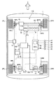
図1は、駆動制御装置を有する車両の一実施形態の概略構成を示す説明図である。また、図2は、図1に示すインバータユニットと電動機とを模式的に示す説明図であり、図3は、制御手段の概略構成を示すブロック図である。図1中の矢印X方向は車両1の進行方向を示す。車両1の進行方向は、車両1が前進する方向である。また、本実施形態において、左右の区別は、車両1が前進する方向を基準とする。すなわち、「左」とは、車両1の前進する方向に向かって左側をいい、「右」とは、車両1の前進する方向に向かって右側をいう。また、車両1が前進する方向を前とし、車両1が後進する方向、すなわち前進する方向とは反対の方向を後とする。 FIG. 1 is an explanatory diagram showing a schematic configuration of an embodiment of a vehicle having a drive control device. FIG. 2 is an explanatory diagram schematically showing the inverter unit and the electric motor shown in FIG. 1, and FIG. 3 is a block diagram showing a schematic configuration of the control means. An arrow X direction in FIG. 1 indicates a traveling direction of the vehicle 1. The traveling direction of the vehicle 1 is a direction in which the vehicle 1 moves forward. In the present embodiment, the left / right distinction is based on the direction in which the vehicle 1 moves forward. That is, “left” refers to the left side in the direction in which the vehicle 1 moves forward, and “right” refers to the right side in the direction in which the vehicle 1 moves forward. Further, the direction in which the vehicle 1 moves forward is defined as the front, and the direction in which the vehicle 1 moves backward, that is, the direction opposite to the direction in which the vehicle 1 moves forward is defined as the rear.
図1に示すように、本実施形態に係る駆動制御装置130は、例えば、乗用車やバス等の車両1に搭載される。また、車両1は、筐体により覆われ、駆動装置108と、ハイブリッド駆動装置110と、駆動制御装置130とを搭載している。また、車両1には、上記各部に加え、車両1として必要な各種構成要素も有する。
As shown in FIG. 1, the
駆動装置108は、車両1の後輪駆動用であり、車両1の左側後輪2RL及び右側後輪2RRを駆動する。また、ハイブリッド駆動装置110は、車両1の前輪駆動用であり、車両1の左側前輪2FL及び右側前輪2FRを駆動する。このように、車両1は、左側後輪2RL、右側後輪2RR、左側前輪2FL及び右側前輪2FRが駆動される、いわゆる四輪駆動の車両である。なお、駆動装置108を車両1の前輪駆動用とし、ハイブリッド駆動装置110を車両1の後輪駆動用として用いてもよい。また、駆動装置108のみを用いて車両1を走行させてもよい。
The
駆動装置108の左側後輪用動力伝達軸9Lには左側後輪制動装置14RLが取り付けられており、右側後輪用動力伝達軸9Rには右側後輪制動装置14RRが取り付けられている。また、ハイブリッド駆動装置110の左側前輪用動力伝達軸6Lには左側前輪制動装置14FLが取り付けられており、右側前輪用動力伝達軸6Rには右側前輪制動装置14FRが取り付けられている。左側後輪制動装置14RL、右側後輪制動装置14RR、左側前輪制動装置14FL及び右側前輪制動装置14FRは、ECU(Engine Control Unit)60によって制御される制動用アクチュエータ13によって、それぞれ独立に制動力を制御することができる。
A left rear wheel braking device 14RL is attached to the left rear wheel
駆動装置108の左側後輪2RLの回転速度は、左側後輪用回転速度センサ45RLによって検出され、右側後輪2RRの回転速度は、右側後輪用回転速度センサ45RRによって検出される。また、ハイブリッド駆動装置110の左側前輪2FLの回転速度は、左側前輪用回転速度センサ45FLによって検出され、右側前輪2FRの回転速度は、右側前輪用回転速度センサ45FRによって検出される。左側前輪用回転速度センサ45FL右側前輪用回転速度センサ45FR、左側後輪用回転速度センサ45RL及び右側後輪用回転速度センサ45RRが検出した左側後輪2RLや右側前輪2FR等の回転速度はECU60及び駆動制御装置130に取り込まれ、車両1の速度(車速)の算出や、車両1の駆動制御等に用いられる。また、ECU60及び駆動制御装置130には、アクセルペダルの開度を検出するアクセル開度センサ42、ブレーキペダルの入力を検出するブレーキセンサ43、ハンドルから入力される操舵角を検出する操舵角センサ44、ヨーレイトを検出するヨーセンサ46、車両1に作用する加速度を検出する加速度センサ47や、車載電源8の電力の残量を検出する電力残量センサ48が接続されている。ECU60及び駆動制御装置130は、これらのセンサの検出値を用いて、車両1が備える駆動装置108や、ハイブリッド駆動装置110や、インバータユニット7を制御する。
The rotational speed of the left rear wheel 2RL of the
駆動装置108は、第1の動力発生手段としての第1電動機11と、第2の動力発生手段としての第2電動機12とを備える。第1電動機11が発生する動力は、第1動力伝達軸である左側後輪用動力伝達軸9Lを介して、第1の駆動輪である左側後輪2RLに付与される。また、第2電動機12が発生する動力は、及び第2動力伝達軸である右側後輪用動力伝達軸9Rを介して、第2の駆動輪である右側後輪2RRへ付与される。このように、本実施形態に係る駆動装置108は、左側後輪2RLと右側後輪2RRとが駆動輪となる。また、駆動装置108は、第1電動機11が左側後輪2RLに動力を付与し、第2電動機12が右側後輪2RRに動力を付与することにより、左側後輪2RLの駆動力と右側後輪2RRの駆動力とを異ならせることができる。
The
第1電動機11及び第2電動機12は、ECU60、及び駆動制御装置130によって制御される。ECU60や駆動制御装置130は、第1電動機11に取り付けられる第1レゾルバ41a及び第2電動機12に取り付けられる第2レゾルバ41bからの情報に基づいて、第1電動機11及び第2電動機12の回転数や回転方向を制御する。また、ECU60や駆動制御装置130は、車両1の走行条件に基づいて、第1電動機11及び第2電動機12の出力を制御する。
The first
第1電動機11及び第2電動機12は、駆動制御装置130を構成するインバータユニット7に接続されている。インバータユニット7には、例えばニッケル−水素電池や鉛蓄電池等の車載電源8が接続されており、インバータユニット7を介して車載電源8から第1電動機11及び第2電動機12へ電力が供給される。ここで、インバータユニット7は、ECU60や駆動制御装置130の制御手段50によって制御される。これによって、車載電源8から第1電動機11及び第2電動機12へ供給される電力や周波数が制御される。なお、制御手段50は、ECU60に内蔵されている。また、第1電動機11と第2電動機12とは独立して制御される。
The first
例えば、本実施形態の車両1は、四輪駆動であり、必要に応じて、左側後輪2RLを駆動する駆動力と、右側後輪2RRを駆動する駆動力とを異なる駆動力とする駆動力配分制御を行う。この駆動力配分制御を実行するにあたっては、ECU60がヨーセンサ46、加速度センサ47、左側後輪用回転速度センサ45RL、右側後輪用回転速度センサ45RR等から取得した情報に基づき、ECU60が車両1の走行条件に応じて要求される、左側後輪2RLと右側後輪2RRとの駆動力差を決定する。そして、決定した駆動力差を発生できるように、インバータユニット7を介して第1電動機11及び第2電動機12の出力を制御する。
For example, the vehicle 1 according to the present embodiment is a four-wheel drive, and if necessary, a driving force that drives the left rear wheel 2RL and a driving force that drives the right rear wheel 2RR are different. Perform distribution control. In executing this driving force distribution control, the
また、ECU60は、旋回時においては、旋回方向における内外輪の回転数差を、左側後輪2RLの回転数又は右側後輪2RRの回転数の少なくとも一方を制御することで吸収する。例えば、右旋回の場合、左側後輪2RLが旋回方向に対する外輪となり、右側後輪2RRが旋回方向に対する内輪となる。したがって、右旋回時には、左側後輪2RLの回転数が右側後輪2RRの回転数よりも大きくなるように、第2電動機12又は第1電動機11の少なくとも一方を駆動する。
Further, during turning, the
一方、左旋回の場合、左側後輪2RLが旋回方向に対する内輪となり、右側後輪2RRが旋回方向に対する外輪となる。したがって、左旋回時には、左側後輪2RLの回転数が右側後輪2RRの回転数よりも小さくなるように、第1電動機11及び/または第2電動機12を駆動する。このように第1電動機11及びまたは第2電動機12を制御し、駆動力配分を行うことで、車両1の旋回性能を向上させることができる。
On the other hand, in the case of a left turn, the left rear wheel 2RL is an inner wheel with respect to the turning direction, and the right rear wheel 2RR is an outer wheel with respect to the turning direction. Accordingly, when turning left, the first
また、第1電動機11や第2電動機12が駆動装置108の動力発生手段として用いられる場合、車載電源8の電力がインバータユニット7を介して供給される。また、例えば車両1の減速時には、第1電動機11が発電機として機能して回生発電を行い、電気エネルギーの形で回収した車両1の運動エネルギーを、車載電源8に蓄えることもできる。これは、ブレーキ信号やアクセルオフ等の信号に基づいて、ECU60や制御手段50がインバータユニット7を制御することにより実現される。
Further, when the first
次に、ハイブリッド駆動装置110は、電動機及び発電機として機能する第3電動機3と、内燃機関5と、変速機(トランスミッション)10とを備える。そして、このハイブリッド駆動装置110は、内燃機関5の出力と第3電動機3の出力とを、例えば遊星歯車装置で構成される変速機10で合成し、左側前輪用動力伝達軸6L及び右側前輪用動力伝達軸6Rを介して、左側前輪2FL及び右側前輪2FRに伝達する。なお、左側前輪2FL及び右側前輪2FRは、車両1の駆動輪であるとともに、操舵輪も兼ねている。
Next, the
このハイブリッド駆動装置110は、いわゆるパラレルハイブリッドの駆動装置である。ハイブリッド駆動装置110は、ECU60によって制御される。また、第3電動機3は、インバータユニット7に接続されており、駆動制御装置130によっても制御される。第3電動機3の回転数及び回転方向は、第3レゾルバ41cによって検出されてECU60及び制御手段50へ取り込まれ、ハイブリッド駆動装置110、第3電動機3の制御に利用される。
The
第3電動機3は、主としてハイブリッド駆動装置110の駆動源、発電機及びスタータモータとして用いられる。このときには、車載電源8によって生み出された電力等がインバータユニット7を介して第3電動機3へ供給される。また、例えば車両1の減速時には、第3電動機3が発電機として機能して回生発電を行い、これによって回収したエネルギーを車載電源8に蓄える。これは、ブレーキ信号やアクセルオフ等の信号に基づいて、ECU60及び/または制御手段50が、インバータユニット7を制御することにより実現される。また、第3発電機3は、内燃機関5によって駆動されることでも、電力を生み出すことができる。
The third
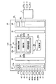
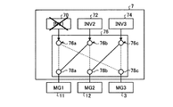
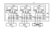
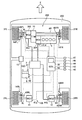
次に、駆動制御装置130について説明する。駆動制御装置130は、インバータユニット7と制御手段50とを有し、第1電動機11、第2電動機12、第3電動機3への車載電源8で生み出される電力の供給を制御する。インバータユニット7は、図2に示すように、第1インバータ70と、第2インバータ72と、第3インバータ74と、切換部76とを有する。
Next, the
第1インバータ70と第2インバータ72と第3インバータ74とは、それぞれ車載電源8と接続されており、切換部76を介して接続された第1電動機11、第2電動機12、第3電動機3と接続されている。第1インバータ70と第2インバータ72と第3インバータ74とは、車載電源8から供給される電流を交流に変換し、さらに、電圧・周波数を調整し、切換部76を介して接続されている接続された第1電動機11、第2電動機12または第3電動機3に供給する。
The
切換部76は、第1切換素子76aと、第2切換素子76bと、第3切換素子76cと、端子78a、端子78b、端子78cとを有する。第1切換素子76aは、一方の端部が第1インバータ70に接続され、他方の端部が端子78aに接続するか、端子78cに接続するかを切換可能な素子である。また、第2切換素子76bは、一方の端部が第2インバータ72と接続され、他方の端部が端子78bに接続するか、端子78aに接続するかを切換可能な素子である。また、第3切換素子76cは、一方の端部が第3インバータ74と接続され、他方の端部が端子78cに接続するか、端子78bに接続するかを切換可能な素子である。また、端子78aは、第1電動機11と接続され、端子78bは、第2電動機12と接続され、端子78cは、第3電動機3と接続されている。
The switching
切換部76は、以上のような構成であり、第1切換素子76aの他方の端部が接続する端子を切り替えることで、第1インバータ70と第1電動機11とが接続している状態と、第1インバータ70と第3電動機3とが接続している状態とを切り換える。また同様に、切換部76は、第2切換素子76bの他方の端部が接続する端子を切り替えることで、第2インバータ72と第2電動機12とが接続している状態と、第2インバータ72と第1電動機11とが接続している状態とを切り換える。また、切換部76は、第3切換素子76cの他方の端部が接続する端子を切り替えることで、第3インバータ74と第3電動機3とが接続している状態と、第3インバータ74と第2電動機12とが接続している状態とを切り換える。具体的には、切換部76は、インバータと接続する電動機を切り換えることで、図2中に実線で示している接続状態から、点線で示している接続状態に切り換える。
The switching
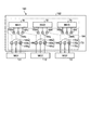
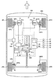
次に制御手段50について説明する。図3は、制御手段の概略構成を示すブロック図である。図3に示すように、制御手段50は、ECU60に組み込まれて構成されている。ECU60は、CPU(Central Processing Unit:中央演算装置)60pと、記憶部60mと、入力ポート65及び出力ポート66と、入力インターフェース67及び出力インターフェース68とから構成される。
Next, the control means 50 will be described. FIG. 3 is a block diagram showing a schematic configuration of the control means. As shown in FIG. 3, the control means 50 is configured to be incorporated in the
なお、ECU60とは別個に、この実施形態に係る制御手段50を用意し、これをECU60に接続してもよい。そして、この実施形態に係る駆動制御を実現するにあたっては、ECU60が備えるインバータユニット7に対する制御機能を、前記制御手段50が利用できるように構成してもよい。
In addition, the control means 50 which concerns on this embodiment may be prepared separately from ECU60, and this may be connected to ECU60. In realizing the drive control according to this embodiment, a control function for the
制御手段50は、故障検出部52と、選択部54と、切換制御部56を有し、インバータユニット7の切換部76の切換動作を制御する。この実施形態において、制御手段50は、ECU60を構成するCPU60pの一部として構成される。
The
故障検出部52は、第1インバータ70、第2インバータ72、第3インバータ74が正常に作動しているか、故障しているかを検出する。ここで、インバータが故障しているかを検出する方法としては、種々の方法を用いることができる。例えば、各インバータをそれぞれの電動機に接続して電動機を駆動させ、制御信号に従って動作しているか、具体的には、電動機が制御信号に従った回転数で回転しているか等を検出し、判定すればよい。
The
選択部54は、第1インバータ70、第2インバータ72及び第3インバータ74のそれぞれが、第1電動機11、第2電動機12及び第3電動機3のいずれと接続するかを決定する。ここで、選択部54は、第1インバータ70、第2インバータ72及び第3インバータ74のうち故障しているインバータがあるか否か、また、車両の走行状態に応じて、各インバータと接続させる電動機を選択する。
The
切換制御部56は、選択部54により選択されたインバータと電動機とを接続させるように切換部76の制御信号を生成する。
The switching
制御手段50の故障検出部52と、選択部54と、切換制御部56とは、バス641、バス642を介して、入力ポート65及び出力ポート66と接続される。これにより、制御手段50を構成する故障検出部52と、選択部54と、切換制御部56とは、相互に制御データをやり取りしたり、一方に命令を出したりできるように構成される。また、CPU60pが備える制御手段50と、記憶部60mとは、バス643を介して接続される。これによって、制御手段50は、ECU60が有する駆動制御装置130の運転制御データを取得し、これを利用することができる。また、制御手段50は、この実施形態に係る駆動制御を、ECU60が予め備えている運転制御ルーチンに割り込ませたりすることができる。
The
入力ポート65には、入力インターフェース67が接続されている。入力インターフェース67には、インバータユニット7の駆動制御に必要な情報を取得するセンサ類が接続されている。本実施形態においては、インバータユニット7の駆動制御に必要な情報を取得するセンサ類として、アクセル開度センサ42、ブレーキセンサ43、操舵角センサ44、左側前輪用回転速度センサ45FL、右側前輪用回転速度センサ45FR、左側後輪用回転速度センサ45RL、右側後輪用回転速度センサ45RR、ヨーセンサ46、加速度センサ47、電力残量センサ48、が接続されている。これらのセンサ類から出力される信号は、入力インターフェース67内のA/Dコンバータ67aやディジタル入力バッファ67dにより、CPU60pが利用できる信号に変換されて入力ポート65へ送られる。これにより、CPU60pは、車両1の運転制御や、インバータユニット7の駆動制御に必要な情報を取得することができる。
An
出力ポート66には、出力インターフェース68が接続されている。出力インターフェース68には、本実施形態に係る駆動制御に必要な制御対象が接続されている。この実施形態では、制御対象として、第1電動機11及び第2電動機12を制御するためのインバータユニット7が、出力インターフェース68に接続されている。
An
出力インターフェース68は、制御回路681、682等を備えており、CPU60pで演算された制御信号に基づき、前記制御対象を動作させる。このような構成により、前記センサ類からの出力信号に基づき、ECU60のCPU60pは、インバータユニット7の切換部76の切換素子76a、76b、76cを制御することができる。
The
記憶部60mには、この実施形態に係る駆動制御の処理手順を含むコンピュータプログラムや制御マップ、あるいはこの実施形態に係る駆動制御に用いるデータ等が格納されている。ここで、記憶部60mは、RAM(Random Access Memory)のような揮発性のメモリ、フラッシュメモリ等の不揮発性のメモリ、あるいはこれらの組み合わせにより構成することができる。
The
上記コンピュータプログラムは、CPU60pへ既に記録されているコンピュータプログラムと組み合わせによって、この実施形態に係る駆動制御の処理手順を実現できるものであってもよい。また、この制御手段50は、前記コンピュータプログラムの代わりに専用のハードウェアを用いて、故障検出部52、選択部54、切換制御部56の機能を実現するものであってもよい。
The computer program may be capable of realizing the drive control processing procedure according to this embodiment in combination with a computer program already recorded in the
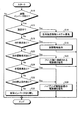
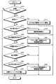
次に、本実施形態に係る駆動制御装置130の駆動制御の一例を説明する。図4は、駆動制御装置による制御の一例を示すフロー図である。また、図5は、図2に示すインバータユニットの切換機構を切り換えた状態を模式的に示す説明図である。まず、ステップS10として、故障検出部52により第1インバータ70、第2インバータ72、第3インバータ74のうち故障しているインバータがあるかを判定する。故障検出部52により、3つのインバータのうちいずれかのインバータが故障していることを検出したら、ステップS12に進み、3つのインバータのいずれもインバータが故障していないことを検出したら、処理を終了する。
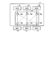
Next, an example of drive control of the
次に、制御手段50の選択部54は、ステップS12として、車両1が旋回中であるかを判定する。ここで、車両1が旋回しているか否かは、操舵角センサ44で検出されるハンドルの操舵角や、ヨーセンサ46により検出されるヨーレイト、加速度センサ47で検出される加速度(特に左右方向の加速度)等に基づいて判定すればよい。なお、これらの検出に用いられるセンサが旋回センサとなる。選択部54は、ステップS12で車両1が旋回中であると判定したらステップS14に進み、車両1が旋回中ではないと判定したらステップS16に進む。
Next, the
選択部54は、ステップS14として、左右独立駆動システムを優先して駆動できるように電動機の優先度を設定する。つまり、左右独立駆動システム優先モードを選択する。本実施形態では、左右独立駆動システムに使用する第1電動機11と第2電動機12とを優先度の高い電動機として設定し、第1電動機11と第2電動機12とを正常に駆動できるように、優先的に正常なインバータと接続させる。
In step S14, the
より具体的には、ステップS10で、図5に示すように、第1インバータ70が故障していることを検出し、ステップS12で車両1が旋回中であると判定したら、ステップS14で、第2インバータ72と第1電動機11とを接続させ、第3インバータ74と第2電動機12とを接続させることを選択する。選択部54でこの選択がされたら切換制御部56は、切換部76の切換素子76bの他方の端部を端子78aと接続させ、切換素子76cの他方の端部を端子78bと接続させる。これにより、第1電動機11は、正常に作動している第2インバータ72により駆動することができ、第2電動機12は、正常に作動している第3インバータ74により駆動させることができ、左右独立駆動システムにより、左側後輪2RLと右側後輪2RRとにそれぞれ異なる駆動力を与えることができ、車両1のヨーレイトを好適に制御することができ好適に旋回を行うことができる。なお、この場合、第3電動機3は、優先度の低い電動機となり電力が供給されず駆動されない。駆動制御装置130は、ステップS14の処理が終了したら処理を終了する。
More specifically, in step S10, as shown in FIG. 5, it is detected that the
次に、選択部54は、ステップS12で車両1が旋回中ではないと判定したら、ステップS16として、四輪駆動要求があるかを判定する。ここで、四輪駆動要求があるかは、操作者の操作により四輪駆動モードとなっているかを検出したり、各種センサの検出値に基づいて、より駆動力が必要な状態であるかを検出したりすることで判定する。選択部54は、ステップS16で、四輪駆動要求があると判定したらステップS18に進み、四輪駆動要求がないと判定したらステップS20に進む。
Next, if it is determined in step S12 that the vehicle 1 is not turning, the
選択部54は、ステップS16で、四輪駆動要求があると判定したら、ステップS18として、副駆動軸を優先して駆動できるように電動機の優先度を設定する。つまり、副駆動軸優先モードを選択する。本実施形態では、副駆動軸側の車輪を駆動させる第1電動機11と第2電動機12とを優先度の高い電動機として設定し、第1電動機11と第2電動機12とを正常に駆動できるように、優先的に正常なインバータと接続させる。本実施形態では、優先度の高い電動機がステップS14の電動機と同様となるので、ステップS14と同様の制御を行う。駆動制御装置130は、ステップS18の処理が終了したら処理を終了する。
If the
次に、選択部54は、ステップS16で四輪駆動要求はないと判定したら、ステップS20として、回生駆動が必要であるかを判定する。ここで、回生駆動が必要であるかは、例えば、アクセル開度センサ42や、ブレーキセンサ43、加速度センサ47等の検出値に基づいて車両1の状態を判定することで回生駆動が必要であるか判定することができる。選択部54は、ステップS20で、回生駆動が必要であると判定したらステップS22に進み、回生駆動が必要ではないと判定したらステップS24に進む。
Next, if the
選択部54は、ステップS20で、回生駆動の必要があると判定したら、ステップS22として、フロント軸(前輪側の軸)に接続される電動機を優先して駆動できるように電動機の優先度を設定する。つまり、フロント軸側電動機優先モードを選択する。本実施形態では、フロント軸側に接続される電動機である第3電動機3を優先度の高い電動機として設定し、第3電動機3を正常に駆動できるように、優先的に正常なインバータと接続させる。駆動制御装置130は、ステップS22の処理が終了したら処理を終了する。
If it is determined in step S20 that regenerative driving is necessary, the
次に、選択部54は、ステップS20で回生駆動の必要はないと判定したら、ステップS24として、充電要求があるかを判定する。ここで、充電要求があるかは、例えば、電力残量センサ48の検出値に基づいて車載電源8の残量を算出し、算出した残量が、充電が必要な残量まで減っているか否かで判定することができる。具体的には、算出した残量が、充電が必要な残量まで減っている場合は、充電要求ありと判定する。選択部54は、ステップS24で、充電要求があると判定したらステップS30に進み、充電要求がないと判定したらステップS28に進む。
Next, if it is determined in step S20 that the regenerative drive is not necessary, the
また、選択部54は、ステップS24で充電要求がないと判定したら、ステップS28として、内燃機関5の停止要求があるかを判定する。各種センサ等の検出値に基づいて車両1の状態を判定することで内燃機関5の停止要求があるか判定することができる。例えば、一定速度での走行が続いており、電動機で発生させる駆動力のみで走行可能であると判定した場合は、内燃機関5の停止要求があると判定する。選択部54は、ステップS28で内燃機関5の停止要求があると判定したらステップS30に進み、停止要求がないと判定したら、ステップS32に進む。
If it is determined in step S24 that there is no charge request, the
次に、選択部54は、ステップS30として、ハイブリッド駆動装置110を構成する電動機を優先して駆動できるように電動機の優先度を設定する。本実施形態では、ハイブリッド駆動装置110を構成する電動機である第3電動機3を優先度の高い電動機として設定し、第3電動機3を正常に駆動できるように、優先的に正常なインバータと接続させる。駆動制御装置130は、ステップS30の処理が終了したら処理を終了する。
Next, the
また、選択部54は、ステップS32としては、故障インバータの切り離しを行う。具体的には、切換部76による切換動作は行わず、そのままの接続状態で、車両を走行させる。選択部54は、ステップS32で故障インバータを切り離したら処理を終了する。
Moreover, the
駆動制御装置130は、車両1の走行状態に応じて、必要な電動機を算出し優先度を設定することで、走行に必要な電動機を正常に駆動させることができる。これにより、一部のインバータが故障した場合も、走行性能を極力低減させることなく走行することができる。また、駆動制御装置130は、一部のインバータが故障している場合も、走行状態によっては優先的に車載電源8の充電を行うこともできるため、より長時間、走行性能を極力低減させることなく走行することができる。また、図4に示すように、優先度の選択にも優先順位を付けることで、走行性能の低下をより低減することができ、操作性や、ドライバビリティも高く維持することができる。
The
なお、制御手段50は、処理が終了した後も、上記処理を一定時間毎、または走行時に断続的に行ことが好ましい。上記処理を繰り返すことで、車両1の走行状態が変化した場合も、その走行状態に応じて、必要な電動機を算出し優先度を設定、走行に必要な電動機を正常に駆動させることができる。これにより、一部のインバータが故障した場合も、走行性能を極力低減させることなく走行することができる。 In addition, it is preferable that the control means 50 performs the said process intermittently at regular time intervals or at the time of driving | running | working after a process is complete | finished. By repeating the above processing, even when the traveling state of the vehicle 1 changes, it is possible to calculate a necessary motor and set a priority according to the traveling state, and to normally drive the motor necessary for traveling. As a result, even when some of the inverters fail, it is possible to travel without reducing travel performance as much as possible.
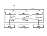
また、上記実施形態では、図2に示すように各インバータに接続された切換素子がそれぞれ2つの電動機と接続可能な構成としたが、本発明はこれに限定されない。図6は、駆動制御装置のインバータユニットの他の一例の概略構成を示す説明図である。ここで、図6に示す駆動制御装置150のインバータユニット152は、切換部154の構成を除いて他の構成は、図2に示すインバータユニット7と同様であるので、同様の構成要素には同一の符号を付しその詳細な説明は簡略化し、以下、インバータユニット152に特有の点を説明する。インバータユニット152は、第1インバータ70と、第2インバータ72と、第3インバータ74と、切換部154とを有する。第1インバータ70と第2インバータ72と第3インバータ74は、上述した図2に示す各インバータと同様の構成である。
Moreover, in the said embodiment, as shown in FIG. 2, although the switching element connected to each inverter was set as the structure which can each be connected with two electric motors, this invention is not limited to this. FIG. 6 is an explanatory diagram showing a schematic configuration of another example of the inverter unit of the drive control device. Here, since the
切換部154は、第1切換素子154aと、第2切換素子154bと、第3切換素子154cと、端子78a、端子78b、端子78cとを有する。ここで、端子78aは、第1電動機11と接続され、端子78bは、第2電動機12と接続され、端子78cは、第3電動機3と接続されている。第1切換素子154aは、一方の端部が第1インバータ70に接続され、他方の端部が端子78aに接続するか、端子78bに接続するか、端子78cに接続するかを切換可能な素子である。また、第2切換素子154bは、一方の端部が第2インバータ72と接続され、他方の端部が端子78aに接続するか、端子78bに接続するか、端子78cに接続するかを切換可能な素子である。また、第3切換素子154cは、一方の端部が第3インバータ74と接続され、他方の端部が端子78aに接続するか、端子78bに接続するか、端子78cに接続するかを切換可能な素子である。つまり、切換部154の各切換素子は、他方の端部が3つの端子78a、78b、78cのいずれとも接続できる構成であり、一方の端部に接続されているインバータを、第1電動機11、第2電動機12、第3電動機3のいずれとも接続させることができる。このように、切換部154により各インバータがそれぞれ全ての電動機と接続できるようにすることで、より簡単な切換動作で正常に動作しているインバータと電動機とを接続させることができる。
The
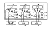
また、上記実施形態では、1つのインバータと1つのモータとを切換部により切り換える単位としたが、本発明はこれに限定されない。例えば、モータに3相の交流電流を供給する場合は、その1相を接続の単位として、各相で接続を切り換えるようにしてもよい。図7は、駆動制御装置のインバータユニットの他の一例を模式的に示す説明図である。ここで、図7に示す駆動制御装置160のインバータユニット162も、切換部164の構成を除いて他の構成は、図2に示すインバータユニット7と同様であるので、同様の構成要素には同一の符号を付しその詳細な説明は簡略化し、以下、インバータユニット162に特有の点を説明する。なお、図7に示す例は、インバータと電動機とにそれぞれ3つの配線が示されているのに対して、図2に示す例は、インバータと電動機とにそれぞれ1つの配線が示されているのみである点で異なる。この点に関しては、図7に示す例では、1つのインバータから電動機に供給する電力を相ごとに示しているのに対し、図2に示す例では、3つの配線をまとめて1つの配線と示している。したがって、インバータ自体と電動機自体は、図2に示す例も図7に示す例も同様のものである。
Moreover, in the said embodiment, although it was set as the unit which switches one inverter and one motor by a switching part, this invention is not limited to this. For example, when a three-phase alternating current is supplied to the motor, the connection may be switched in each phase with one phase as a unit of connection. FIG. 7 is an explanatory diagram schematically illustrating another example of the inverter unit of the drive control device. Here, since the
インバータユニット162は、第1インバータ70と、第2インバータ72と、第3インバータ74と、切換部164とを有する。第1インバータ70と第2インバータ72と第3インバータ74は、上述した図2に示す各インバータと同様の構成である。なお、第1インバータ70、第2インバータ72、第3インバータ74の各インバータは、電動機を駆動させるための3相の電流を出力するための3つの端子を有する。
切換部164は、第1切換素子164aと、第2切換素子164bと、第3切換素子164c、第4切換素子164dと、第5切換素子164eと、第6切換素子164fと、第7切換素子164gと、第8切換素子164hと、第9切換素子164iと、第1端子ユニット166と、第2端子ユニット168と、第3端子ユニット170とを有する。
The
まず、第1端子ユニット166と、第2端子ユニット168と、第3端子ユニット170について説明する。第1端子ユニット166は、第1電動機11にU相、V相、W相の3相の電流をそれぞれ入力する3つの入力部とそれぞれ接続されているU相端子166a、V相端子166b、W相端子166cとで構成されている。また、第2端子ユニット168は、第2電動機12にU相、V相、W相の3相の電流をそれぞれ入力する3つの入力部とそれぞれ接続されているU相端子168a、V相端子168b、W相端子168cとで構成されている。第3端子ユニット170は、第3電動機3にU相、V相、W相の3相の電流をそれぞれ入力する3つの入力部とそれぞれ接続されているU相端子170a、V相端子170b、W相端子170cとで構成されている。なお、以下では、各電動機の各相と接続されている端子を、電動機の端子という。例えば、第1電動機11のU相と接続されているU相端子166aは、第1電動機11のU相端子166aという。
First, the first
第1切換素子164aは、一方の端部が第1インバータ70の1つの端子に接続され、他方の端部が第1電動機11のU相端子166aに接続するか、V相端子166bに接続するかを切換可能な素子である。第2切換素子164bは、一方の端部が第1インバータ70の1つの端子に接続され、他方の端部が第1電動機11のV相端子166bに接続するか、W相端子166cに接続するかを切換可能な素子である。第3切換素子164cは、一方の端部が第1インバータ70の1つの端子に接続され、他方の端部が第1電動機11のW相端子166cに接続するか、第2電動機12のU相端子168aに接続するかを切換可能な素子である。なお、第1切換素子164a、第2切換素子164b、第3切換素子164cの一方の端部は、第1インバータ70の別々の端子と接続されている。
One end of
第4切換素子164dは、一方の端部が第2インバータ72の1つの端子に接続され、他方の端部が第2電動機12のU相端子168aに接続するか、V相端子168bに接続するかを切換可能な素子である。第5切換素子164eは、一方の端部が第2インバータ72の1つの端子に接続され、他方の端部が第2電動機12のV相端子168bに接続するか、W相端子168cに接続するかを切換可能な素子である。第6切換素子164fは、一方の端部が第2インバータ72の1つの端子に接続され、他方の端部が第2電動機12のW相端子168cに接続するか、第3電動機3のU相端子170aに接続するかを切換可能な素子である。なお、第4切換素子164d、第5切換素子164e、第6切換素子164fの一方の端部は、第2インバータ72の別々の端子と接続されている。
The
第7切換素子164gは、一方の端部が第3インバータ74の1つの端子に接続され、他方の端部が第3電動機3のU相端子170aに接続するか、V相端子170bに接続するかを切換可能な素子である。第8切換素子164hは、一方の端部が第3インバータ74の1つの端子に接続され、他方の端部が第3電動機3のV相端子170bに接続するか、W相端子170cに接続するかを切換可能な素子である。第9切換素子164iは、一方の端部が第3インバータ74の1つの端子に接続され、他方の端部が第3電動機3のW相端子170cに接続するか、第1電動機11のU相端子166aに接続するかを切換可能な素子である。なお、第7切換素子164g、第8切換素子164h、第9切換素子164iの一方の端部は、第3インバータ74の別々の端子と接続されている。
The
切換部166は、以上のような構成であり、各端子ユニットの切換素子を切り換えることでインバータと電動機との接続を電動機の相ごと、つまり、電動機のU相、V相、W相のそれぞれに接続されるインバータの端子を別々に切り換える。以下、図8−1及び図8−2を用いて切換動作について詳細に説明する。ここで、図8−1及び図8−2は、それぞれ図7に示すインバータユニットの切換部を切り替えた状態を模式的に示す説明図である。
The
例えば、切換部164がインバータと電動機を図8−1に示すように接続させている場合、具体的には、第1切換素子164a、第2切換素子164b、第3切換素子164cが第1インバータ70と第1電動機11とを接続させ、第4切換素子164d、第5切換素子164e、第6切換素子164fが、第2インバータ72と第2電動機12とを接続させ、第7切換素子164g、第8切換素子164h、第9切換素子164iが第2インバータ72と第3電動機3とを接続させている場合、第1インバータ70のうち第1切換素子164aが接続している部分が故障しているとする。この場合は、第1インバータ70から第1切換素子164a及びU相端子168aを介して、第1電動機11に電力が供給されなくなるため、第1電動機11は、正常に駆動されなくなる。
For example, when the
この時、駆動制御装置150の制御手段50により左右独立駆動モードが選択されたら、つまり、第1電動機11及び第2電動機12の優先度が高くなったら、図8−2に示すように、第9切換素子164iを、第3インバータ74と第3電動機3のW相端子170cとを接続させている状態から、第3インバータ74と第1電動機11のU相端子164aとを接続させている状態に切り換える。これにより、第1電動機11のU相には、第3インバータ74から電力が供給され、第1電動機11を正常に駆動させることができる。なお、このとき、第3電動機3は、正常に駆動できなくなる。
At this time, if the left and right independent drive mode is selected by the control means 50 of the
このように駆動制御装置150のように、各電動機の相ごとに接続を切り換えるようにすることで、インバータの故障発生時に接続を切り換える端子を少なくすることができる。また、インバータと電動機とを対応させて切り換える場合よりも配線を簡単にすることができる。つまり、インバータと電動機とを対応させる場合は、1つのインバータと2つの電動機との間で、それぞれ3つの相を接続する配線と切換装置が必要となるが、図7に示す例では、1つの端子が隣接する2つの相との接続を切り換えればよいため、配線が簡単になる。また、このような場合でも、切換素子を順次切り換えることで、いずれのインバータが故障した場合も他のインバータで電動機を正常に作動させることができる。
In this way, by switching the connection for each phase of each electric motor as in the
ここで、このようにインバータ及び電動機の端子単位で切り換える場合は、接続を切り換える切換素子が接続されているインバータと電動機との接続を一度遮断し、接続を切り換えるインバータを、切換後に接続される電動機のインバータ制御と同期させてから切換素子を切り換えるようにすること好ましい。つまり、切り替え前に、動作を停止させる電動機の動作を停止させ、インバータを、新たに電力を供給する電動機の動作に同期させた後に、切換を行うことが好ましい。このようにインバータの同期制御をしてから切換を行うことで、優先される電動機とシームレスな接続を行うことができ、優先される電動機をより好適に動作させることができる。 Here, when switching in units of terminals of the inverter and the motor as described above, the connection between the inverter and the motor to which the switching element for switching the connection is disconnected is once cut off, and the inverter that switches the connection is connected to the motor that is connected after the switching. It is preferable to switch the switching element after synchronizing with the inverter control. That is, before switching, it is preferable to perform switching after stopping the operation of the electric motor that stops the operation and synchronizing the inverter with the operation of the electric motor that supplies new power. Thus, by performing switching after performing synchronous control of the inverter, it is possible to make a seamless connection with the prioritized motor and to operate the prioritized motor more suitably.
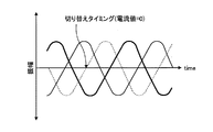
また、駆動制御装置は、切り換える切換素子が接続しているインバータの端子から出力される電流の電流値が0、または実質的に0となるタイミングで、切り換えることが好ましい。図9は、インバータの各端子に流れる電流の振幅と時間との関係を示すグラフである。インバータでは、図9に示すように3つの端子からそれぞれ位相が120度異なる電流が生成され、出力されている。ここで、インバータの3種類の端子のうち、図9中点線で示す電流を出力する端子と接続されている切換素子の接続を切り換える場合は、図9中矢印で示したタイミングで切換素子と、電動機の各相の端子との接続を切り換えることが好ましい。このように電流値が0となるタイミングで接続を切り換えることで、切換素子及び電動機への負荷を少なくすることができ、切換素子の切換により故障が発生することを抑制できる。 Further, the drive control device preferably switches at a timing when the current value of the current output from the terminal of the inverter connected to the switching element to be switched becomes 0 or substantially 0. FIG. 9 is a graph showing the relationship between the amplitude of the current flowing through each terminal of the inverter and time. In the inverter, as shown in FIG. 9, currents having phases different from each other by 120 degrees are generated and output from three terminals. Here, among the three types of terminals of the inverter, when switching the connection of the switching element connected to the terminal that outputs the current indicated by the dotted line in FIG. 9, the switching element at the timing indicated by the arrow in FIG. It is preferable to switch the connection with each phase terminal of the electric motor. By switching the connection at the timing when the current value becomes 0 in this way, the load on the switching element and the electric motor can be reduced, and the occurrence of a failure due to the switching of the switching element can be suppressed.
また、駆動制御装置は、インバータの各素子に加わる逆起電力を検出する逆起電力検出センサを設け、閾値以上の逆起電力が発生したら、切換部の切換素子を電動機側の端子と接触していない状態に切り替えるようにすることが好ましい。このように、切換素子が電動機側の端子と接触していない状態とすることで、逆起電力で発生する電圧を降下させ、インバータに故障が発生することを抑制することができる。 Further, the drive control device is provided with a back electromotive force detection sensor for detecting a back electromotive force applied to each element of the inverter, and when a back electromotive force exceeding the threshold is generated, the switching element of the switching unit is brought into contact with the terminal on the motor side. It is preferable to switch to a state that is not. Thus, by setting the switching element not in contact with the terminal on the electric motor side, it is possible to reduce the voltage generated by the back electromotive force and suppress the occurrence of a failure in the inverter.
また、インバータの故障を判定する場合は、切換部が故障しているかも判定するようにすることが好ましい。ここで、切換部が故障しているかは、切換素子を切り換え、その切り替えた後に測定されるヨーレイトと、切り換えた状態から算出されるヨーレイトの目標値とを比較し、両者の値の差分に基づいて、切換部の切換素子が故障しているかを判定する。このように、実際に切り換えて算出される結果に基づいて、判定することで、別途回路や、インバータを監視するセンサを設けることなく、故障原因を特定することができる。 Further, when determining the failure of the inverter, it is preferable to determine whether or not the switching unit has failed. Here, whether or not the switching unit is out of order is based on the difference between the values obtained by switching the switching element, comparing the yaw rate measured after the switching and the target value of the yaw rate calculated from the switched state. Then, it is determined whether the switching element of the switching unit is out of order. Thus, by determining based on the result calculated by actually switching, the cause of the failure can be specified without providing a separate circuit or a sensor for monitoring the inverter.
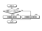
また、駆動制御装置は、故障インバータがあることを検出したら車載電源8の充電を判定する電力残量の閾値、例えば、充電開始の電力残量、充電終了の電力残量を切り換えることが好ましい。具体的には、通常時は、充電開始の閾値を電力残量が満充電の30%としているのに対して、故障インバータがある場合は、充電開始の閾値を電力残量が満充電の50%とすることが好ましい。また、充電開始電力は、通常時よりも故障インバータがある場合の方が高い残量とし、充電終了の閾値は、通常時よりも故障インバータがある場合の方が高い残量とし、また、適正な電力残量と判定する電力残量も通常時よりも故障インバータがある場合の方が高い残量とする。このように、故障インバータが発生した場合は、車載電源8の充電を判定する電力残量の閾値を切り換え、より車載電源8の電池残量が多い状態を維持するようにすることが好ましい。予め車載電源の残量を多く、充電率が高い状態を維持することで、故障インバータがあり、電動機の発電機としての機能が低下した場合でも、長時間の走行が可能となる。また、通常期と故障インバータの発生時とで切り換えることで、車載電源が過充電になることも抑制でき、車載電源の寿命が短縮することも抑制できる。
Moreover, it is preferable that the drive control device switches a remaining power threshold value for determining charging of the in-
以下、故障インバータがあることを検出したら車載電源8の充電を判定する電力残量の閾値を切り換える制御の一例を説明する。ここで、図10は、駆動制御装置による制御の他の一例を示すフロー図である。まず、駆動制御装置は、ステップS40として、故障インバータがないかを判定する。駆動制御装置は、ステップS40で、故障インバータがない(Yes)と判定した場合は、ステップS42に進み、充電閾値を通常値、つまり、通常時の閾値に設定して、処理を終了する。他方、駆動制御装置は、故障インバータがある(No)と判定したら、ステップS44に進み、充電閾値を高充電率側に切り換えて、つまり、故障インバータ発生時の閾値に切り換えて、処理を終了する。このように、故障インバータの有無で、充電の閾値を切り換えることで、上記効果を得ることができる。
Hereinafter, an example of control for switching the threshold value of the remaining power for determining charging of the in-
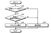
また、駆動制御装置は、故障インバータあることを検出した場合に、変速中であったり、変速の可能性が大きかったりするときは、ハイブリッド駆動装置110に使用している電動機を優先度の高い電動機とすることが好ましい。以下、具体的な制御例とともに説明する。図11は、駆動制御装置による制御の他の一例を示すフロー図である。まず、駆動制御装置は、ステップS50として、故障インバータがあるかを判定する。駆動制御装置は、ステップS50で、故障インバータがある(Yes)と判定したら、ステップS52に進み、故障インバータがない(No)と判定した場合は、ステップS56に進む。
Further, when the drive control unit detects that there is a faulty inverter and the gear is being changed or the possibility of the change is high, the electric motor used for the
次に、駆動制御装置は、ステップS50で、故障インバータがある(Yes)と判定したら、ステップS52として、変速中、または、変速の可能性が高いかを判定する。ここで、変速中、または、変速の可能性が高いかは、加速度や、アクセルペダルの入力、変速比、内燃機関の回転数等に基づいて判定する。駆動制御装置は、ステップS52で、変速中、または、変速の可能性が高いと判定したらステップS54に進み、変速中ではなく、変速の可能性が低いと判定したらステップS56に進む。 Next, if it is determined in step S50 that there is a faulty inverter (Yes), the drive control apparatus determines in step S52 whether or not there is a high possibility of shifting. Here, whether or not there is a high possibility of shifting is determined based on acceleration, input of an accelerator pedal, a gear ratio, the number of revolutions of the internal combustion engine, and the like. If it is determined in step S52 that the gear shift is in progress or the possibility of gear shift is high, the drive control device proceeds to step S54.
次に、駆動制御装置は、ステップS52で、変速中、または、変速の可能性が高いと判定したら、ステップS54として、ハイブリッドシステムを優先する。つまり、ハイブリッド駆動装置110に使用している電動機を優先度の高い電動機とする。図1に示す車両1では、第3電動機3を優先度の高い電動機として設定する。駆動制御装置は、ステップS54の処理が終了したら、処理を終了する。
Next, when it is determined in step S52 that the gear is being shifted or the possibility of shifting is high, the drive control device gives priority to the hybrid system in step S54. That is, the electric motor used in the
また、駆動制御装置は、ステップS50で故障インバータがない(No)と判定したら、または、ステップS52で変速中ではなく、変速の可能性が低いと判定したら、ステップS56として、通常制御とし、処理を終了する。ここで、通常制御とは、現状の優先度を維持したままの制御である。 If it is determined in step S50 that there is no faulty inverter (No), or if it is determined in step S52 that the gear is not being shifted and the possibility of shifting is low, normal control is performed in step S56. Exit. Here, the normal control is control while maintaining the current priority.
このように、変速中や、変速の可能性が大きい場合は、ハイブリッド駆動装置110に使用している電動機を正常に駆動させ、電動機により補助をしつつ変速を行うことで、無段変速を実施することができ、変速段を切り替える際に発生する衝撃を低減することができる。
As described above, when the speed is changed or when the possibility of the speed change is large, the electric motor used in the
なお、図11では、変速中または変速の可能性が大きいかのみの判定を示したが、この判定を上述した図4に示す制御に組み合わせるようにしてもよい。この場合は、ステップS20とステップS24との間に組み込むようにすることが好ましい。 Note that FIG. 11 shows only the determination of whether or not there is a high possibility of shifting, but this determination may be combined with the control shown in FIG. 4 described above. In this case, it is preferable to incorporate between step S20 and step S24.
また、駆動制御装置は、ハイブリッド駆動装置110に使用している電動機の優先度が高くない状態で、変速する場合、例えば、旋回時や四輪駆動の要求がある場合等は、固定段変速とすることが好ましい。
In addition, when the drive control device shifts in a state where the priority of the electric motor used in the
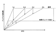
また、駆動制御装置は、故障インバータがあると判定した場合は、通常時よりも内燃機関の回転数が低い時に変速を行うように、変速のタイミングを切り換えることが好ましい。ここで、図12は、入力軸の回転数と速度との関係を示すグラフである。ここで、図12は、横軸がSPDであり、縦軸がインプット回転数、つまり、内燃機関の回転数である。図12に示すように、故障インバータがある場合は、通常時よりも、内燃機関の回転数が低いとき、つまり低速で走行している場合に変速を行うことが好ましい。言い換えれば、故障インバータがある場合は、通常時よりも変速を行う基準回転数を低く設定することが好ましい。 In addition, when the drive control device determines that there is a faulty inverter, it is preferable to switch the shift timing so that the shift is performed when the number of revolutions of the internal combustion engine is lower than normal. Here, FIG. 12 is a graph showing the relationship between the rotational speed and speed of the input shaft. Here, in FIG. 12, the horizontal axis is SPD, and the vertical axis is the input rotational speed, that is, the rotational speed of the internal combustion engine. As shown in FIG. 12, when there is a faulty inverter, it is preferable to perform a shift when the rotational speed of the internal combustion engine is lower than normal, that is, when traveling at a low speed. In other words, when there is a faulty inverter, it is preferable to set the reference rotational speed at which gear shifting is performed to be lower than normal.
このように、内燃機関の回転数が低いとき変速を行うことで、変速の時に発生するか回転数差を小さくすることができ、電動機により変速の補助ができず固定段変速を行う場合も、クラッチ等の摩擦材の負担を軽減することができる。また、変速時の挙動変化も小さくすることができ、ドライバビリティの低下を抑制することができる。 Thus, by performing a shift when the rotation speed of the internal combustion engine is low, it is possible to reduce the difference in rotation speed that occurs at the time of the shift, or even when performing a fixed-stage shift without assisting the shift by the electric motor, The burden of friction materials such as clutches can be reduced. In addition, a change in behavior at the time of shifting can be reduced, and a decrease in drivability can be suppressed.
また、駆動制御装置は、故障インバータがあると判定した場合は、坂道に居ると検出した場合を除いて、通常よりも1段高速側の変速段、例えば2速で発進させることが好ましい。このように、通常よりも1段高速側で発進させることで、変速回数を低減することができ、固定段変速を行う回数も低減することができる。これにより、変速機にかかる負担を小さくすることができる。また、このような発進時は、主駆動軸、副駆動軸のいずれかで通常時よりも大きな駆動力で発進の補助を行うことで、高速側の変速段を使用してもスムーズに発進させることができる。 In addition, when it is determined that there is a faulty inverter, the drive control device preferably starts at a gear position that is one speed higher than normal, for example, the second speed, unless it is detected that the vehicle is on a slope. As described above, the number of shifts can be reduced and the number of fixed-stage shifts can be reduced by starting the vehicle on the high-speed side of the first stage. Thereby, the burden concerning a transmission can be made small. Also, at such a start, either the main drive shaft or the sub drive shaft assists the start with a larger driving force than usual, so that the start can be made smoothly even if the high-speed side gear is used. be able to.
また、ハイブリッド駆動装置110が変速時に電動機を利用し、かつ、変速部にロック機構を有する変速機構である場合は、故障インバータ発生時は、ロック機構を利用して、原動機を発生させる反力を発生させるようにすることが好ましい。このように、ロック機構で反力を発生させることで、電動機を用いることなく変速でき、変速に用いる電動機に電力を供給しているインバータを他の電動機への電力の供給に使用することができる。
In addition, when the
また、図1に示す実施形態では、ハイブリッドシステムをパラレルハイブリットの駆動装置としたが、これに限定されず、いわゆるシリーズ・パラレルハイブリッドの駆動装置としてもよい。図13は、駆動制御装置を有する車両の他の実施形態の概略構成を示す説明図である。なお、図13に示す車両200は、基本的に、ハイブリッド駆動装置202の構成を除いて、他の構成は図1に示す車両1と同様である。以下では、車両1と同様の構成の部分の説明は簡略化または省略し、車両200に特有の点を重点的に説明する。車両200は、筐体により覆われ、駆動装置108と、ハイブリッド駆動装置202と、駆動制御装置130とを搭載している。
In the embodiment shown in FIG. 1, the hybrid system is a parallel hybrid drive device, but is not limited to this, and may be a so-called series / parallel hybrid drive device. FIG. 13 is an explanatory diagram showing a schematic configuration of another embodiment of a vehicle having a drive control device. The
ハイブリッド駆動装置202は、電動機及び発電機として機能する第3電動機203及び第4電動機204と、内燃機関5と、変速機10とを備える。そして、このハイブリッド駆動装置202は、内燃機関5の出力と第3電動機203の出力とを、例えば遊星歯車装置で構成される変速機10で合成し、左側前輪用動力伝達軸6L及び右側前輪用動力伝達軸6Rを介して、左側前輪2FL及び右側前輪2FRに伝達する。なお、左側前輪2FL及び右側前輪2FRは、車両1の駆動輪であるとともに、操舵輪も兼ねている。また、第3電動機203の回転数及び回転方向は、第3レゾルバ41cによって検出され、第4電動機204の回転数及び回転方向は、第4レゾルバ41dによって検出されてECU60及び制御手段50へ取り込まれ、ハイブリッド駆動装置202、第3電動機203、第4電動機204の制御に利用される。
The
このハイブリッド駆動装置202は、いわゆるシリーズ・パラレルハイブリッドの駆動装置である。ハイブリッド駆動装置202は、ECU60によって制御される。第3電動機203は、インバータユニット7に接続されている。
The
第3電動機203は、主としてハイブリッド駆動装置202の駆動源として用いられる。このときには、車載電源8や、第4電動機204によって生み出された電力等がインバータユニット7を介して第3電動機203へ供給される。また、例えば車両200の減速時には、第3電動機203が発電機として機能して回生発電を行い、これによって回収したエネルギーを車載電源8に蓄える。これは、ブレーキ信号やアクセルオフ等の信号に基づいて、ECU60がインバータユニット7を制御することにより実現される。
The third
第4電動機204は、主として発電機として機能するが、内燃機関5の始動時には、スタータモータとして機能する。第4電動機204が発電機として機能するときには、第4電動機204が内燃機関5によって駆動される。また、車両1の走行中においては、第4電動機204が内燃機関5の駆動反力を受けることにより、左側前輪2FL及び右側前輪2FRに駆動力を発生させる。第4電動機204で生み出される電力は第3電動機203の駆動に用いられる他、車載電源8の充電にも用いられる。
The fourth
また、駆動制御装置130のインバータユニット7は、4つのインバータを有し、各電動機に電力を供給させる。また、車両200では、インバータが4つに増加したが、車両の状態に応じて電動機の優先度を設定し、その優先度が高い電動機に優先的に正常なインバータからの電力を供給するのは、上述の実施例と同様である。本実施形態では、第3電動機203は、フロント軸側の電動機、ハイブリッド駆動装置202の電動機となり、第4電動機204は、ハイブリッド駆動装置202の電動機となる。このように1つの車両に4つの電動機を用いる場合も駆動制御装置130により制御を行うことで、上述と同様の効果をえることができる。
Further, the
また、本実施形態のように、ハイブリッド駆動装置202として第3電動機203と第4電動機204を用いる場合は動力循環を行うことができる。図14を用いて、動力循環ができる場合の駆動制御装置130の制御の一例について説明する。ここで、図14は、駆動制御装置による制御の一例を示すフロー図である。なお、図14に示す制御は、ステップS24とステップS28との間にステップS26を追加した点を除いて、図4に示す制御と同様であるので、以下、ステップS24からステップS28までの処理のみを説明する。
In addition, when the third
選択部54は、ステップS20で回生駆動の必要はない(No)と判定したら、ステップS24として、充電要求があるかを判定する。ここで、充電要求があるかは、例えば、電力残量検出センサ48の検出値に基づいて車載電源8の残量を算出し、算出した残量が、充電が必要な残量まで減っているか否かで判定することができる。具体的には、算出した残量が、充電が必要な残量まで減っている場合は、充電要求ありと判定する。選択部54は、ステップS24で充電要求がある(Yes)と判定したらステップS30に進み、充電要求がない(No)と判定したらステップS26に進む。
If it is determined in step S20 that the regenerative drive is not required (No), the
選択部54は、ステップS24で充電要求がない(No)と判定したら、ステップS26として、動力循環の要求があるかを判定する。ここで、動力循環の要求があるかは、各種センサ等の検出値に基づいて車両1の状態を判定することで判定することができる。選択部54は、ステップS26で、動力循環の要求がある(Yes)と判定したらステップS30に進み、動力循環の要求がない(No)と判定したらステップS28に進む。
If it is determined in step S24 that there is no charge request (No), the
選択部54は、ステップS26で動力循環の要求がない(No)と判定したら、ステップS28として、内燃機関5の停止要求があるかを判定する。各種センサ等の検出値に基づいて車両1の状態を判定することで内燃機関5の停止要求があるか判定することができる。例えば、一定速度での走行が続いており、電動機で発生させる駆動力のみで走行可能であると判定した場合は、内燃機関5の停止要求があると判定する。選択部54は、ステップS28で内燃機関5の停止要求がある(Yes)と判定したらステップS30に進み、停止要求がない(No)と判定したら、ステップS32に進む。このように、車両200では、動力循環の要求があるか否かによっても、電動機の優先度を判定するようにすることが好ましい。
If it is determined in step S26 that there is no request for power circulation (No), the
また、車両200では、駆動装置108を車両200の後輪駆動用とし、ハイブリッド駆動装置202を車両200の前輪駆動用として用いたが、駆動装置108を車両の前輪駆動用とし、ハイブリッド駆動装置202を車両1の後輪駆動用として用いてもよい。以下、図15とともに説明する。ここで、図15は、駆動制御装置を有する車両の他の実施形態の概略構成を示す説明図である。図15に示す車両300は、駆動装置の配置をのぞいて他の点は、図13に示す車両200と同様であるので、以下、車両300に特徴的な点を重点的に説明する。
In the
車両300は、筐体により覆われ、駆動装置302と、ハイブリッド駆動装置304と、駆動制御装置130とを搭載している。駆動装置302は、車両300の前輪駆動用であり、車両300の左側前輪2FL及び右側前輪2FRを駆動する。また、ハイブリッド駆動装置304は、車両300の後輪駆動用であり、車両300の左側後輪2RL及び右側後輪2RRを駆動する。このように、車両300は、左側後輪2RL、右側後輪2RR、左側前輪2FL及び右側前輪2FRが駆動される、いわゆる四輪駆動の車両である。駆動装置302と、ハイブリッド駆動装置304との各部の構成は、車両200の各部と同様である。
The
また、本実施形態では、第1電動機11及び第2電動機12は、左右独立駆動に用いる電動機、副駆動軸側の電動機、フロント軸側の電動機となり、第3電動機203及び第4電動機204は、ハイブリッド駆動装置304の電動機となる。駆動制御装置130は、故障インバータがある場合は、車両状態に応じて、各電動機の優先度を設定し、電動機に電力を供給する。このように、ハイブリッド駆動装置で後輪を駆動させる場合も車両1と同様の制御を行うことができ、同様の効果を得ることができる。
In the present embodiment, the
また、上記実施形態では、左右の駆動輪に別々の電動機を接続させ、左右独立駆動をおこなったが、これに限定されず、1つの電動機と動力分配機構とを設け、1つの電動機から出力される駆動力を動力分配機構により分配して、左右の駆動輪に異なる駆動力を伝達するようにしてもよい。 In the above embodiment, separate motors are connected to the left and right drive wheels to perform left and right independent drive. However, the present invention is not limited to this, and one motor and a power distribution mechanism are provided and output from one motor. The driving force may be distributed by a power distribution mechanism to transmit different driving forces to the left and right driving wheels.
なお、上記実施形態では、ハイブリッド駆動装置を有する車両として説明したが、車両としては、複数のモータを複数のインバータにより駆動する車両であればよく、例えば、電気自動車にも用いることができる。 In the above-described embodiment, the vehicle having a hybrid drive device has been described. However, the vehicle may be a vehicle that drives a plurality of motors by a plurality of inverters, and can be used for an electric vehicle, for example.
以上のように、本発明にかかる駆動制御装置は、2つ以上のモータと2つ以上のインバータを有する車両の駆動力制御に有用であり、特に、インバータに故障が発生しても車両を走行させることに適している。 As described above, the drive control device according to the present invention is useful for controlling the driving force of a vehicle having two or more motors and two or more inverters. In particular, the vehicle travels even if a failure occurs in the inverter. Suitable for making
1、200、300 車両
2FL 左側前輪
2FR 右側前輪
2RL 左側後輪
2RR 右側後輪
3 第3電動機
5 内燃機関
6R、6L、9L、9R 動力伝達軸
7、152、162 インバータユニット
8 車載電源
10 変速機
11 第1電動機
12 第2電動機
13 制動用アクチュエータ
41a、41b、41c、41d レゾルバ
42 アクセル開度センサ
43 ブレーキセンサ
44 操舵角センサ
45FL、45FR、45RL、45RR 回転速度センサ
46 ヨーセンサ
47 加速度センサ
48 電力残量センサ
50 制御手段
52 故障検出部
54 選択部
56 切換制御部
60 ECU
70 第1インバータ
72 第2インバータ
74 第3インバータ
76、154、164 切換部
76a〜76c、154a〜154c、164a〜164i 切換素子
78a、78b、78c 端子
108 駆動装置
110 ハイブリッド駆動装置
130、150、160 駆動制御装置
204 第4電動機
1, 200, 300 Vehicle 2FL Left front wheel 2FR Right front wheel 2RL Left rear wheel 2RR Right
70
Claims (10)
前記電動機に供給する電力を制御し、前記電動機を駆動させる2つ以上のインバータと、
前記インバータが故障しているかを検出する故障検出手段と、
前記インバータが制御する前記電動機を選択する選択手段とを有し、
前記選択手段は、前記故障検出手段により前記インバータが故障していることを検出したら、前記車両の走行状態に基づいて、優先的に駆動させる電動機を判定し、優先度の高い電動機に正常に作動している前記インバータからの電力を供給させることを特徴とする駆動制御装置。 A drive control device for a vehicle having two or more electric motors for rotating wheels,
Two or more inverters for controlling electric power supplied to the electric motor and driving the electric motor;
Fault detection means for detecting whether the inverter is faulty;
Selecting means for selecting the electric motor controlled by the inverter;
When the failure detecting means detects that the inverter has failed, the selection means determines a motor to be preferentially driven based on a running state of the vehicle, and operates normally to a motor with high priority. The drive control apparatus characterized by supplying the electric power from the said inverter.
前記電動機に供給する電力を制御し、前記電動機を駆動させる2つ以上のインバータと、
前記電動機に供給する電力を蓄電する蓄電手段と、
前記インバータが故障しているかを検出する故障検出手段と、
前記インバータが制御する前記電動機を選択する選択手段とを有し、
前記2つ以上の電動機の内の1つの電動機は、前記内燃機関で生成される出力を電力として取り出し、前記蓄電手段に蓄電させ、
前記選択手段は、前記故障検出手段により前記インバータが故障していることを検出したら、前記車両の走行状態に基づいて、優先的に駆動させる電動機を判定し、優先度の高い電動機に正常に作動している前記インバータからの電力を供給させることを特徴とする駆動制御装置。 A drive control device for a vehicle having an internal combustion engine as a drive source for rotating the wheel and two or more electric motors for rotating the wheel,
Two or more inverters for controlling electric power supplied to the electric motor and driving the electric motor;
Power storage means for storing power to be supplied to the motor;
Fault detection means for detecting whether the inverter is faulty;
Selecting means for selecting the electric motor controlled by the inverter;
One of the two or more electric motors takes out an output generated by the internal combustion engine as electric power, causes the electric storage means to store the electric power,
When the failure detecting means detects that the inverter has failed, the selection means determines a motor to be preferentially driven based on a running state of the vehicle, and operates normally to a motor with high priority. The drive control apparatus characterized by supplying the electric power from the said inverter.
前記2つ以上の電動機のうち2つの電動機は、一方の電動機が前記車両の右側の車輪を駆動させ、他方の電動機が左側の車輪を駆動させるものであり、
前記選択手段は、前記旋回センサの検出結果に基づいて車両が旋回していると判定したら、前記一方の電動機及び前記他方の電動機を優先度の高い電動機に設定することを特徴とする請求項1または2に記載の駆動制御装置。 Furthermore, it has a turn sensor that detects whether the vehicle is turning,
Of the two or more electric motors, two electric motors are such that one electric motor drives the right wheel of the vehicle and the other electric motor drives the left wheel.
The selection means sets the one electric motor and the other electric motor to high priority motors when it is determined that the vehicle is turning based on the detection result of the turning sensor. Or the drive control apparatus of 2.
前記変速機構の変速段の切り替えと、電動機の駆動力の制御により、変速比を制御する変速制御手段とを有し、
前記変速制御手段は、前記一方の電動機及び前記他方の電動機を優先度の高い電動機に設定されている場合は、駆動機構の変速比を変速機構の変速段の切り替えのみで切り換えることを特徴とする請求項1から3のいずれか1項に記載の駆動制御装置。 The vehicle has a speed change mechanism having a plurality of speed stages,
Shift control means for controlling the gear ratio by switching the gear stage of the transmission mechanism and controlling the driving force of the electric motor;
The shift control means switches the gear ratio of the drive mechanism only by switching the shift stage of the transmission mechanism when the one motor and the other motor are set to high priority motors. The drive control apparatus of any one of Claim 1 to 3.
前記蓄電判定手段は、前記故障検出手段によりインバータが故障していることを検出したら、前記蓄電手段の蓄電を開始する電力残量の閾値をより高い閾値に切り換えることを特徴とする請求項1から7のいずれか1項に記載の駆動制御装置。 Furthermore, it has power storage determination means for determining whether to store power in the power storage means,
The power storage determining means switches the remaining power threshold value for starting power storage of the power storage means to a higher threshold value when the failure detection means detects that the inverter has failed. 8. The drive control device according to any one of 7 above.
前記電動機の各相の端子に接続する前記インバータの端子を切り換える切換機構を有することを特徴とする請求項1から8のいずれか1項に記載の駆動制御装置。 The electric motor is a multi-phase electric motor,
The drive control device according to claim 1, further comprising a switching mechanism that switches a terminal of the inverter connected to a terminal of each phase of the electric motor.
Priority Applications (1)
| Application Number | Priority Date | Filing Date | Title |
|---|---|---|---|
| JP2009040280A JP2010200426A (en) | 2009-02-24 | 2009-02-24 | Drive controller |
Applications Claiming Priority (1)
| Application Number | Priority Date | Filing Date | Title |
|---|---|---|---|
| JP2009040280A JP2010200426A (en) | 2009-02-24 | 2009-02-24 | Drive controller |
Publications (1)
| Publication Number | Publication Date |
|---|---|
| JP2010200426A true JP2010200426A (en) | 2010-09-09 |
Family
ID=42824552
Family Applications (1)
| Application Number | Title | Priority Date | Filing Date |
|---|---|---|---|
| JP2009040280A Pending JP2010200426A (en) | 2009-02-24 | 2009-02-24 | Drive controller |
Country Status (1)
| Country | Link |
|---|---|
| JP (1) | JP2010200426A (en) |
Cited By (12)
| Publication number | Priority date | Publication date | Assignee | Title |
|---|---|---|---|---|
| JP2012224185A (en) * | 2011-04-19 | 2012-11-15 | Honda Motor Co Ltd | Vehicle drive device |
| CN103781650A (en) * | 2011-04-07 | 2014-05-07 | 克劳斯·埃伯特 | Method for operating a vehicle |
| US8768551B2 (en) | 2011-04-19 | 2014-07-01 | Honda Motor Co., Ltd. | Vehicle driving apparatus |
| JP2014128155A (en) * | 2012-12-27 | 2014-07-07 | Kobe Steel Ltd | Inverter system for construction machine |
| US9688153B2 (en) | 2014-06-13 | 2017-06-27 | Mitsubishi Jidosha Kogyo Kabushiki Kaisha | Electric vehicle |
| JP2017140991A (en) * | 2016-02-12 | 2017-08-17 | 本田技研工業株式会社 | vehicle |
| JP2017147791A (en) * | 2016-02-15 | 2017-08-24 | トヨタ自動車株式会社 | Control device for hybrid vehicle |
| JP2018024385A (en) * | 2016-08-12 | 2018-02-15 | トヨタ自動車株式会社 | Hybrid automobile |
| CN108683270A (en) * | 2018-06-08 | 2018-10-19 | 深圳市汇森无线传输有限公司 | A kind of wireless charging system |
| JP2020048310A (en) * | 2018-09-19 | 2020-03-26 | 株式会社Subaru | Electric car |
| US11267457B2 (en) * | 2019-12-09 | 2022-03-08 | Ford Global Technologies, Llc | Systems and methods for managing electric motor torques in a hybrid electric vehicle |
| JP2023009339A (en) * | 2021-07-07 | 2023-01-20 | 日立Astemo株式会社 | Vehicle control device |
Citations (3)
| Publication number | Priority date | Publication date | Assignee | Title |
|---|---|---|---|---|
| JPH05130712A (en) * | 1991-10-21 | 1993-05-25 | Hitachi Ltd | Electric vehicle controller |
| JP2001078303A (en) * | 1999-09-07 | 2001-03-23 | Toshiba Corp | Vehicle drive |
| JP2006129662A (en) * | 2004-11-01 | 2006-05-18 | Nissan Motor Co Ltd | Driving force control device and driving force control method |
-
2009
- 2009-02-24 JP JP2009040280A patent/JP2010200426A/en active Pending
Patent Citations (3)
| Publication number | Priority date | Publication date | Assignee | Title |
|---|---|---|---|---|
| JPH05130712A (en) * | 1991-10-21 | 1993-05-25 | Hitachi Ltd | Electric vehicle controller |
| JP2001078303A (en) * | 1999-09-07 | 2001-03-23 | Toshiba Corp | Vehicle drive |
| JP2006129662A (en) * | 2004-11-01 | 2006-05-18 | Nissan Motor Co Ltd | Driving force control device and driving force control method |
Cited By (20)
| Publication number | Priority date | Publication date | Assignee | Title |
|---|---|---|---|---|
| CN103781650A (en) * | 2011-04-07 | 2014-05-07 | 克劳斯·埃伯特 | Method for operating a vehicle |
| JP2014515249A (en) * | 2011-04-07 | 2014-06-26 | エベルト、クラウス | Vehicle operation method |
| CN103781650B (en) * | 2011-04-07 | 2016-08-17 | 克劳斯·埃伯特 | method used to run the vehicle |
| US8768551B2 (en) | 2011-04-19 | 2014-07-01 | Honda Motor Co., Ltd. | Vehicle driving apparatus |
| JP2012224185A (en) * | 2011-04-19 | 2012-11-15 | Honda Motor Co Ltd | Vehicle drive device |
| JP2014128155A (en) * | 2012-12-27 | 2014-07-07 | Kobe Steel Ltd | Inverter system for construction machine |
| US9688153B2 (en) | 2014-06-13 | 2017-06-27 | Mitsubishi Jidosha Kogyo Kabushiki Kaisha | Electric vehicle |
| JP2017140991A (en) * | 2016-02-12 | 2017-08-17 | 本田技研工業株式会社 | vehicle |
| JP2017147791A (en) * | 2016-02-15 | 2017-08-24 | トヨタ自動車株式会社 | Control device for hybrid vehicle |
| US10407057B2 (en) | 2016-08-12 | 2019-09-10 | Toyota Jidosha Kabushiki Kaisha | Hybrid vehicle |
| JP2018024385A (en) * | 2016-08-12 | 2018-02-15 | トヨタ自動車株式会社 | Hybrid automobile |
| CN108683270A (en) * | 2018-06-08 | 2018-10-19 | 深圳市汇森无线传输有限公司 | A kind of wireless charging system |
| CN108683270B (en) * | 2018-06-08 | 2024-05-14 | 深圳市爱克信智能股份有限公司 | Wireless charging system |
| JP2020048310A (en) * | 2018-09-19 | 2020-03-26 | 株式会社Subaru | Electric car |
| CN110920395A (en) * | 2018-09-19 | 2020-03-27 | 株式会社斯巴鲁 | Electric automobile |
| US10978984B2 (en) | 2018-09-19 | 2021-04-13 | Subaru Corporation | Electric vehicle |
| CN110920395B (en) * | 2018-09-19 | 2024-11-15 | 株式会社斯巴鲁 | Electric Vehicles |
| US11267457B2 (en) * | 2019-12-09 | 2022-03-08 | Ford Global Technologies, Llc | Systems and methods for managing electric motor torques in a hybrid electric vehicle |
| JP2023009339A (en) * | 2021-07-07 | 2023-01-20 | 日立Astemo株式会社 | Vehicle control device |
| JP7628904B2 (en) | 2021-07-07 | 2025-02-12 | 日立Astemo株式会社 | Vehicle control device |
Similar Documents
| Publication | Publication Date | Title |
|---|---|---|
| JP2010200426A (en) | Drive controller | |
| US9283948B2 (en) | Vehicle and control method for vehicle | |
| US7999499B2 (en) | Rotating electrical machine control system and vehicle drive system | |
| US6984954B2 (en) | Diagnostic strategy for an electric motor using sensorless control and a position sensor | |
| US8169177B2 (en) | Electric vehicle | |
| US7594491B2 (en) | Internal combustion engine start controller | |
| US8718854B2 (en) | Electrically-powered vehicle and method for controlling the same | |
| US20090319107A1 (en) | Hybrid vehicle,control method of hybrid vehicle, and computer readable recording medium recording program for causing computer to execute control of hybrid vehicle | |
| JP2013103516A (en) | Vehicle and control method for vehicle | |
| JP2010000834A (en) | Power output device, control method thereof, and vehicle | |
| JP2010098876A (en) | Vehicle control system | |
| JP2009248707A (en) | Rotary electrical machine control system | |
| JP2010119158A (en) | Electric vehicle, controller for electric vehicle, and control program for electric vehicle | |
| JP6344338B2 (en) | Hybrid vehicle | |
| JP2018079790A (en) | Hybrid car | |
| JP2016124523A (en) | Hybrid automobile | |
| JP2013180647A (en) | Vehicle | |
| JP6947016B2 (en) | Electric vehicle | |
| JP5758778B2 (en) | Vehicle and vehicle control method | |
| JP2011207336A (en) | Hybrid vehicle | |
| JP6618308B2 (en) | Vehicle control device | |
| JP6332298B2 (en) | vehicle | |
| JP7013885B2 (en) | automobile | |
| JP2016049867A (en) | Hybrid car | |
| US11529945B2 (en) | Hybrid vehicle and control method thereof |
Legal Events
| Date | Code | Title | Description |
|---|---|---|---|
| A621 | Written request for application examination |
Free format text: JAPANESE INTERMEDIATE CODE: A621 Effective date: 20111129 |
|
| A131 | Notification of reasons for refusal |
Free format text: JAPANESE INTERMEDIATE CODE: A131 Effective date: 20130319 |
|
| A02 | Decision of refusal |
Free format text: JAPANESE INTERMEDIATE CODE: A02 Effective date: 20130709 |