JP2010194722A - Patch transfer medium - Google Patents
Patch transfer medium Download PDFInfo
- Publication number
- JP2010194722A JP2010194722A JP2009038753A JP2009038753A JP2010194722A JP 2010194722 A JP2010194722 A JP 2010194722A JP 2009038753 A JP2009038753 A JP 2009038753A JP 2009038753 A JP2009038753 A JP 2009038753A JP 2010194722 A JP2010194722 A JP 2010194722A
- Authority
- JP
- Japan
- Prior art keywords
- layer
- transfer
- patch
- hologram
- liquid crystal
- Prior art date
- Legal status (The legal status is an assumption and is not a legal conclusion. Google has not performed a legal analysis and makes no representation as to the accuracy of the status listed.)
- Pending
Links
Images



Landscapes
- Decoration By Transfer Pictures (AREA)
- Credit Cards Or The Like (AREA)
- Ink Jet (AREA)
- Thermal Transfer Or Thermal Recording In General (AREA)
- Polarising Elements (AREA)
- Ink Jet Recording Methods And Recording Media Thereof (AREA)
- Holo Graphy (AREA)
Abstract
【課題】
被転写体にパッチを容易に転写でき、多数回の繰り返し使用でも、媒体の表面と保護する耐擦傷性や耐溶剤性などに加えて、簡易な真正性判定が可能なコレステリック液晶層、ホログラム、有色反射性パターン層及び透明反射層を有するパッチ転写媒体を提供する。
【解決手段】
支持基材及び剥離性樹脂層からなる支持材が、前記剥離性樹脂層面に転写材を担持し、前記転写材を分断するハーフカット処理によってパッチとしたパッチ転写媒体において、
前記支持材の剥離性樹脂層側から、透明基材、コレステリック液晶層、ホログラム形成層、有色反射性パターン層、透明反射層及び接着層が順に積層されていることを特徴とし、また、上記コレステリック液晶層が偏光性を有することを特徴とする。
【選択図】 図1【Task】
Cholesteric liquid crystal layers, holograms, which can easily transfer patches to the transfer target, and can easily determine authenticity in addition to scratch resistance and solvent resistance to protect the surface of the medium even after repeated use. A patch transfer medium having a colored reflective pattern layer and a transparent reflective layer is provided.
[Solution]
In a patch transfer medium in which a support material composed of a support base material and a peelable resin layer carries a transfer material on the surface of the peelable resin layer and is patched by a half-cut process for dividing the transfer material,
A transparent base material, a cholesteric liquid crystal layer, a hologram forming layer, a colored reflective pattern layer, a transparent reflective layer, and an adhesive layer are laminated in order from the peelable resin layer side of the support material. The liquid crystal layer has a polarizing property.
[Selection] Figure 1
Description
本発明は、パッチ転写媒体に関し、さらに詳しくは、転写後は耐擦傷性や耐溶剤性などの耐久性に加えて、意匠性とセキュリティ性に優れるコレステリック液晶、ホログラム、有色反射性パターン層及び透明反射層を有するパッチを、転写性よく転写できるパッチ転写媒体に関するものである。このパッチ転写媒体は、偽造防止機能を必要とする種々の形状を有する物(以下、被転写体という。)の所望の部分に正確に転写して用いられる。
「パッチ」とは、請求項に記載のとおり、支持基材上に剥離性樹脂層を介して、設けられた転写材の、一部分のみをハーフカットして、そのハーフカット部分のみを転写するときの、その「転写部分」をいう。
さらに、このパッチ転写媒体の接着層に、熱溶融転写方式、熱昇華転写方式又はインクジェット方式のいずれかで、被転写体への転写形成が必要な画像を設けておき、この転写によって位置精度よく被転写体上に形成することにより、偽造防止媒体(非転写体にパッチ転写媒体を転写したものをいう。)及び形成画像の真正性を耐久性よく証明することに用いられるパッチ転写媒体に関するものである。
本明細書において、配合を示す「比」、「部」、「%」などは特に断わらない限り質量基準であり、「/」印は一体的に積層されていることを示す。また、「PET」は「ポリエチレンテレフタレート」、「エクストルージョンコーティング」は「EC」、の略語、同意語、機能的表現、通称、又は業界用語である。
The present invention relates to a patch transfer medium. More specifically, after transfer, in addition to durability such as scratch resistance and solvent resistance, cholesteric liquid crystal, hologram, colored reflective pattern layer, and transparent, which are excellent in design and security. The present invention relates to a patch transfer medium capable of transferring a patch having a reflective layer with good transferability. This patch transfer medium is used by accurately transferring to a desired portion of a product having various shapes that require a forgery prevention function (hereinafter referred to as a transfer target).
“Patch” means when only a part of the transfer material provided on the support substrate is half-cut through the releasable resin layer, and only the half-cut part is transferred. This “transcription part”.
Furthermore, an image that needs to be transferred to a transfer target is provided on the adhesive layer of the patch transfer medium by any one of the hot-melt transfer method, the thermal sublimation transfer method, and the ink-jet method, and this transfer provides high positional accuracy. Related to anti-counterfeit medium (referred to a patch transfer medium transferred to a non-transfer body) and patch transfer medium used to prove the authenticity of the formed image with high durability by forming on the transfer target It is.
In the present specification, “ratio”, “part”, “%” and the like indicating the blending are based on mass unless otherwise specified, and the “/” mark indicates that they are integrally laminated. “PET” is an abbreviation, synonym, functional expression, common name, or industry term for “polyethylene terephthalate” and “extrusion coating” is “EC”.
(主なる用途)本発明のパッチ転写媒体主なる用途としては、偽造防止分野、具体的には、クレジットカード等の、偽造されて使用されると、カード保持者やカード会社等に損害を与え得るもの、運転免許証、社員証、会員証等の身分証明書、入学試験用の受験票、パスポート等、紙幣、商品券、ポイントカード、株券、証券、抽選券、馬券、預金通帳、乗車券、通行券、航空券、種々の催事の入場券、遊戯券、交通機関や各種電話用のプリペイドカード等がある。
これらはいずれも、経済的、もしくは社会的な価値を有する情報や、本人識別等の情報を保持した情報記録体であり、偽造による損害を防止する目的で、記録体そのものの真正性を識別できる機能を有することが望まれるが、その中でも、その情報が目視画像であって、その目視画像の真正性を証明する機能を有することが特に望まれるものに適用される。
さらには、その目視画像の耐久性、すなわち、耐擦傷性や耐溶剤性等を高めることが望まれるものに適用される。
また、上記した用途以外であっても、高額商品、例えば、高級腕時計、高級皮革製品、貴金属製品、もしくは宝飾品等の、しばしば、高級ブランド品と言われるもの、または、それら高額商品の収納箱やケース等も偽造され得るものである。また、量産品でも有名ブランドのもの、例えば、オーディオ製品、電化製品等、または、それらに吊り下げられるタグも、偽造の対象となりやすい。
さらに、著作物である音楽ソフト、映像ソフト、コンピュータソフト、もしくはゲームソフト等が記録された記憶体、またはそれらのケース等も、やはり偽造の対象となり得る。また、プリンター用のトナー、用紙など、交換する備品を純正材料に限定している製品などにも、偽造による損害を防止する目的で、そのものの真正性を識別できる機能を有することが望まれる。
これらのものに、目視画像を形成し、且つ、その目視画像の真正性を証明する必要のあるものにも好適である。
(Main use) The patch transfer medium of the present invention is mainly used in the field of forgery prevention, specifically, credit cards, etc., and damage to the cardholder or card company when used forgery. Obtained, driver's license, identification card such as employee ID card, membership card, entrance examination card for entrance examination, passport, banknote, gift certificate, point card, stock certificate, securities, lottery ticket, horse ticket, passbook, boarding pass , Pass tickets, air tickets, admission tickets for various events, play tickets, prepaid cards for transportation and various telephones.
All of these are information records that hold information of economic or social value, identity identification, etc., and can identify the authenticity of the record itself for the purpose of preventing damage caused by forgery. Although it is desired to have a function, among these, the information is a visual image, and the present invention is applied to a case where it is particularly desired to have a function of proving the authenticity of the visual image.
Further, the present invention is applied to those in which it is desired to improve the durability of the visual image, that is, scratch resistance, solvent resistance, and the like.
In addition to the uses described above, expensive products such as luxury watches, luxury leather products, precious metal products, jewelry, etc., often referred to as luxury brand products, or storage boxes for these expensive products And cases can also be forged. In addition, mass-produced products of famous brands, such as audio products, electrical appliances, etc., or tags that are hung on them are also subject to forgery.
Furthermore, a storage body in which music software, video software, computer software, game software, or the like, which is a copyrighted work, or cases thereof can also be forged. In addition, it is desirable that products such as printer toner, paper, and the like in which supplies to be replaced are limited to genuine materials have a function of identifying their authenticity for the purpose of preventing damage caused by forgery.
It is also suitable for those in which a visual image is formed on these materials and the authenticity of the visual image needs to be proved.
(背景技術)従来、上記の用途の媒体、例えば、一定の金額を払い込んだ(プリペイドという)権利や資格などを証明する媒体が増加している。該媒体は一定の経済的価値や効果を持つため、有効期間や区間、氏名、年齢などの個別情報が改竄されて、不正に偽造、変造、不正使用することが絶えず、種々の改竄防止策が提案され、セキュリティ性の向上が図られている。
また、優れた美観、意匠性とともに、高いセキュリティ性を持つホログラム転写箔を用いて、ホログラムを媒体へ転写することが知られている。ホログラム転写箔は、基本的には基材フィルム上に、剥離層または、離型層と保護層、ホログラム形成層、ホログラム効果層および接着層を設け、カードなどの被転写材の転写領域に対向させて接着し、接着後に基材フィルムを剥離して、カードなどの被転写材の表面にホログラム形成層を転写する。
上記ホログラム転写箔は、ホログラム形成層の変造や偽造が困難であることから、被転写物品の偽造、変造が有効に防止されているが、各種模倣、偽造、変造技術の向上によりさらに優れた偽造防止性、変造防止性が要求されるようになってきた。
(Background Art) Conventionally, a medium for the above-mentioned use, for example, a medium for certifying a right or qualification for which a certain amount of money has been paid (called prepaid) is increasing. Since the medium has a certain economic value and effect, individual information such as the validity period, section, name, and age is falsified, and it is constantly falsified, altered, and illegally used. It has been proposed to improve security.
It is also known to transfer a hologram to a medium using a hologram transfer foil having high security as well as excellent aesthetics and design. A hologram transfer foil is basically provided with a release layer or a release layer and a protective layer, a hologram forming layer, a hologram effect layer, and an adhesive layer on a base film, and faces a transfer area of a transfer material such as a card. Then, the base film is peeled off after the adhesion, and the hologram forming layer is transferred onto the surface of a transfer material such as a card.
The hologram transfer foil is difficult to counterfeit or counterfeit the hologram forming layer, so that counterfeiting and counterfeiting of the article to be transferred is effectively prevented. Prevention property and alteration prevention property have been required.
一方、上記の用途の媒体、例えば、IDカードでは媒体の表面へ文字、数字、顔写真等のような画像が形成される。これらの画像の形成は、近年、所謂溶融転写タイプ又は昇華転写タイプのインクリボンを用いて熱転写又は昇華転写による転写法で行われることが多い。該転写法は基材シート上に着色転写層を形成した熱転写シートにおいて、その背面からサーマルヘッドなどにより、画像状に加熱して、上記の着色転写層を熱転写受像シートの表面に熱転写して、画像形成するものである。この熱転写方法は、その着色転写層の構成によって、昇華転写型と熱溶融転写型の二方式に大別される。両方式ともに、フルカラー画像の形成が可能であり、例えば、イエロー、マゼンタ、シアンさらに必要に応じて、ブラックの三色ないし四色の熱転写シートを用意し、同一の熱転写受像シートの表面に各色の画像を重ねて熱転写して、フルカラー画像を形成するものである。
マルチメディアに関連した様々なハードおよびソフトの発達により、この熱転写方法は、コンピューターグラフィックス、衛星通信による静止画像そしてCDROMその他に代表されるデジタル画像およびビデオ等のアナログ画像のフルカラーハードコピーシステムとして、その市場を拡大している。
この熱転写方法による熱転写受像シートの具体的な用途は、多岐にわたっている。代表的なものとしては、印刷の校正刷り、画像の出力、CAD/CAMなどの設計およびデザインなどの出力、CTスキャンや内視鏡カメラなどの各種医療用分析機器、測定機器の出力用途そしてインスタント写真の代替として、また身分証明書やIDカード、クレジットカード、その他カード類への顔写真などの出力、さらに遊園地、ゲームセンター、博物館、水族館などのアミューズメント施設における合成写真、記念写真としての用途などをあげることができる。
On the other hand, in a medium for the above-mentioned use, for example, an ID card, images such as letters, numbers, and facial photographs are formed on the surface of the medium. In recent years, these images are often formed by a transfer method by thermal transfer or sublimation transfer using a so-called melt transfer type or sublimation transfer type ink ribbon. The transfer method is a thermal transfer sheet in which a colored transfer layer is formed on a base sheet, and is heated in an image form from the back by a thermal head or the like, and the above-described colored transfer layer is thermally transferred to the surface of the thermal transfer image receiving sheet. An image is formed. This thermal transfer method is roughly classified into a sublimation transfer type and a thermal melt transfer type depending on the configuration of the colored transfer layer. Both types can form full-color images.For example, yellow, magenta, and cyan, if necessary, black or three-color thermal transfer sheets are prepared, and the surface of the same thermal transfer image-receiving sheet has each color. The images are superimposed and thermally transferred to form a full color image.
With the development of various hardware and software related to multimedia, this thermal transfer method has become a full-color hard copy system for analog images such as digital images and video such as still images by computer graphics, satellite communications, and CDROM and others. That market is expanding.
The specific application of the thermal transfer image receiving sheet by this thermal transfer method is diverse. Typical examples include printing proofs, image output, CAD / CAM design and design output, various medical analytical instruments such as CT scans and endoscopic cameras, measuring instrument output applications and instant As an alternative to photos, output of ID cards, ID cards, credit cards, other face photos on cards, etc., as well as composite photos and amusement photos at amusement facilities such as amusement parks, game centers, museums, and aquariums Etc.
(先行技術)
上記のような用途の多様化に伴い、受容層が基材上に剥離可能に設けられた中間転写媒体で、その受容層に染料層を有する熱転写シートを用いて、染料を転写して画像を形成し、その後に中間転写記録媒体を加熱して、受容層を被転写体上に転写する方法が提案されている。(例えば、特許文献1参照)
特に、昇華転写型の熱転写シートで画像形成した場合、顔写真等の階調性画像を精密に形成することができるが、通常の印刷インキによる画像とは異なり、耐候性、耐摩擦性、耐薬品性等の耐久性に欠ける弱点がある。その解決策として、熱転写画像上に熱転写性樹脂層を有する保護層熱転写フィルムを重ね合わせ、サーマルヘッドや加熱ロール等を用いて、透明性を有する熱転写性樹脂層を転写させ、画像上に保護層を形成することが行われている。
上記の保護層はサーマルヘッドまたは熱ロールによる転写時に、部分的に転写する必要があることから、箔切れ性を有する必要がある。この場合、保護層を数ミクロン程度の厚さの樹脂膜にせざるを得ないことから、強靱な耐擦傷性、耐薬品性等の耐久性を持たせることが出来ない。また、中間転写記録媒体に形成する保護層も箔切れ性の観点から、充分な耐擦傷性、耐薬品性等の耐久性を持たせることが出来ない。
インクジェット方式に至っては、インクジェットプリンターによりフルカラートナーを静電的手法により被印字部へ飛ばして印字する(画像形成する)ものであり、被印字部に接触しないという利点があるものの、被印字部への接着性は弱く、その印字(画像)の耐久性は著しく低いと言わざるを得ない。
(Prior art)
With the diversification of applications as described above, an image is obtained by transferring a dye by using a thermal transfer sheet having a dye layer on the receiving layer, which is an intermediate transfer medium in which the receiving layer is detachably provided on the substrate. A method is proposed in which the intermediate transfer recording medium is formed and then the intermediate transfer recording medium is heated to transfer the receptor layer onto the transfer medium. (For example, see Patent Document 1)
In particular, when an image is formed with a sublimation transfer type thermal transfer sheet, a gradation image such as a facial photograph can be accurately formed, but unlike an image with a normal printing ink, weather resistance, friction resistance, There are weaknesses that lack durability such as chemical properties. As a solution, a protective layer thermal transfer film having a thermal transfer resin layer is superimposed on the thermal transfer image, and the thermal transfer resin layer having transparency is transferred using a thermal head, a heating roll, or the like, and the protective layer is formed on the image. Has been made to form.
Since the protective layer described above needs to be partially transferred at the time of transfer by a thermal head or a heat roll, it needs to have a foil cutting property. In this case, since the protective layer has to be a resin film having a thickness of about several microns, durability such as tough scratch resistance and chemical resistance cannot be provided. In addition, the protective layer formed on the intermediate transfer recording medium cannot be provided with sufficient durability such as scratch resistance and chemical resistance from the viewpoint of foil breakage.
The ink jet system is to print (image formation) by ejecting full-color toner to the print target portion by an electrostatic method by an ink jet printer, and has an advantage of not contacting the print target portion, but to the print target portion. Therefore, it is necessary to say that the durability of the printing (image) is extremely low.
また、樹脂層を設けたシート基材と、受容層を設けた透明シートが積層され、受容層を含めて透明シート部にハーフカット処理が施され、透明シート上にホログラム形成層が積層され、樹脂層と透明シートの間で剥離する中間転写記録媒体の製造方法において、透明シート上にホログラム形成層が積層された原反上に、受容層を塗布し、その後に透明シートの受容層の設けられている面と反対面と、予め1画面単位毎に相当する位置にレジマークを形成したシート基材とを樹脂層を介して貼り合わせ、次にレジマークを読み取って、ハーフカット処理の位置合わせとハーフカット処理を行なうことを特徴とすることが記載されている。この文献における中間転写記録媒体を使用して、過酷な使用条件においても、熱転写画像の各種耐久性に優れ、保護層(透明シート)を画像上に、ハーフカット処理がされているので、精度良く、簡単に転写することができ、また透明シート上にホログラム画像が形成してあるため、熱転写の画像形成された被転写体の改ざん、偽造防止性に優れたものとなることが記載されている。(ホログラムパッチ転写媒体。例えば、特許文献2参照) In addition, a sheet base material provided with a resin layer and a transparent sheet provided with a receiving layer are laminated, a half cut treatment is performed on the transparent sheet portion including the receiving layer, and a hologram forming layer is laminated on the transparent sheet, In a method for producing an intermediate transfer recording medium that peels between a resin layer and a transparent sheet, a receiving layer is applied on the raw material on which the hologram forming layer is laminated on the transparent sheet, and then the receiving layer of the transparent sheet is provided. Half-cut processing position by pasting the opposite surface to the sheet surface and the sheet base material on which the registration mark is formed in advance at the position corresponding to each screen unit through the resin layer, and then reading the registration mark It is described that the alignment and half-cut processing are performed. Using the intermediate transfer recording medium in this document, it is excellent in various durability of thermal transfer images even under severe usage conditions, and the protective layer (transparent sheet) is half-cut on the image, so it is accurate It is described that it can be easily transferred and that a hologram image is formed on a transparent sheet, so that it is excellent in falsification and anti-counterfeiting of a transferred object on which a thermal transfer image is formed. . (Hologram patch transfer medium. For example, see Patent Document 2)
しかしながら、近年、ホログラムそのものの偽造が高度になり、ホログラム画像があることを目視判定するだけの真正性判定では、そのホログラムが真正に製造されたものか否か明確に判断できず、偽造品を排除することが難しい状況となっている。また、その真正性判定を、例えば金融機関の窓口や、デパートの売り場の照明下で実施した場合、照明そのものがホログラムの再生には不向きなことが多く(波長単一性や、位相が揃ったものでなく、目に優しく光を散乱させた蛍光灯のように、多くの波長が混在した散乱光である場合が多い。)、ホログラムの目視判定のみを真正性判定のよりどころとすることはもはや不十分であるという欠点を有していた。 However, in recent years, forgery of the hologram itself has become more sophisticated, and authenticity determination by merely visually determining that there is a hologram image cannot clearly determine whether the hologram is genuinely manufactured. It is difficult to eliminate. In addition, when the authenticity is determined, for example, under the illumination of a financial institution or department store, the illumination itself is often unsuitable for hologram reproduction (wavelength uniformity and phase alignment). In many cases, it is scattered light with many wavelengths mixed together, such as fluorescent lamps that gently scatter light in the eyes.) Only the visual judgment of the hologram is used as the basis for authenticity judgment. It had the disadvantage that it was no longer sufficient.
そこで、本発明はこのような問題点を解消するためになされたものである。その目的は、カードなどの偽造防止媒体(本発明では被転写体と呼ぶ。)に、熱転写等によって形成した画像を保護する、もしくは、熱転写等によって形成した画像を有する、耐久性の高いパッチを転写形成し、過酷な使用条件においても、その画像の各種耐久性に優れ、また、パッチを被転写体上に位置精度良く、容易に転写でき(画像があるべき位置に精度よく転写される。)、転写された媒体においては、簡便な判定方法により、真正性が容易に、且つ、正確に判断できるというセキュリティ面において優れたコレステリック液晶とホログラム、有色反射性パターン層及び透明反射層とを有するパッチ転写媒体を提供する。
すなわち、媒体使用時、耐久性を有し、多数回の繰り返し使用でも、媒体の表面が保護されるとともに、簡易な手段によりその真正性が正確に判断できるパッチ転写媒体を提供する。
Accordingly, the present invention has been made to solve such problems. The purpose is to provide a highly durable patch that protects an image formed by thermal transfer or the like on an anti-counterfeit medium such as a card (referred to as a transfer object in the present invention) or has an image formed by thermal transfer or the like. The transfer is formed, and the various durability of the image is excellent even under severe use conditions, and the patch can be easily transferred onto the transfer medium with high positional accuracy (the image is accurately transferred to the position where the image should be). ) The transferred medium has a cholesteric liquid crystal, a hologram, a colored reflective pattern layer, and a transparent reflective layer, which are excellent in security that authenticity can be easily and accurately judged by a simple judgment method. A patch transfer medium is provided.
That is, it provides a patch transfer medium that is durable when the medium is used, the surface of the medium is protected even after repeated use, and the authenticity can be accurately determined by simple means.
上記の課題を解決するために、
本発明のパッチ転写媒体の第1の態様は、
支持基材及び剥離性樹脂層からなる支持材が、前記剥離性樹脂層面に転写材を担持し、前記転写材を分断するハーフカット処理によってパッチとしたパッチ転写媒体において、
前記支持材の剥離性樹脂層側から、透明基材、コレステリック液晶層、ホログラム形成層、有色反射性パターン層、透明反射層及び接着層が順に積層されてなることを特徴とする。
本発明のパッチ転写媒体の第1の態様によれば、
支持基材及び剥離性樹脂層からなる支持材が、前記剥離性樹脂層面に転写材を担持し、前記転写材を分断するハーフカット処理によってパッチとしたパッチ転写媒体において、
前記支持材の剥離性樹脂層側から、透明基材、コレステリック液晶層、ホログラム形成層、有色反射性パターン層、透明反射層及び接着層が順に積層されてなることを特徴とするパッチ転写媒体が提供される。
このパッチ転写媒体により、前記透明基材を備えた前記コレステリック液晶層、前記ホログラム形成層、前記有色反射性パターン層、前記透明反射層と、前記接着層が、パッチとして、被転写体(パッチが転写されて、偽造防止媒体となるもの。)に転写される。被転写体は、前記パッチ転写前に、熱溶融転写方式、熱昇華転写方式又はインクジェット方式のいずれかであらかじめ画像が形成されており、この画像に対して位置精度よくパッチが転写される。
To solve the above problem,
The first aspect of the patch transfer medium of the present invention includes:
In a patch transfer medium in which a support material composed of a support base material and a peelable resin layer carries a transfer material on the surface of the peelable resin layer and is patched by a half-cut process for dividing the transfer material,
A transparent substrate, a cholesteric liquid crystal layer, a hologram forming layer, a colored reflective pattern layer, a transparent reflective layer, and an adhesive layer are laminated in that order from the peelable resin layer side of the support material.
According to the first aspect of the patch transfer medium of the present invention,
In a patch transfer medium in which a support material composed of a support base material and a peelable resin layer carries a transfer material on the surface of the peelable resin layer and is patched by a half-cut process for dividing the transfer material,
A patch transfer medium comprising a transparent base material, a cholesteric liquid crystal layer, a hologram forming layer, a colored reflective pattern layer, a transparent reflective layer, and an adhesive layer, which are laminated in this order from the side of the peelable resin layer of the support material. Provided.
With this patch transfer medium, the cholesteric liquid crystal layer provided with the transparent substrate, the hologram forming layer, the colored reflective pattern layer, the transparent reflective layer, and the adhesive layer are used as a patch. Transferred to a medium for preventing forgery). Prior to the patch transfer, an image is formed in advance on the transfer target by any one of the thermal melting transfer method, the thermal sublimation transfer method, and the ink jet method, and the patch is transferred to the image with high positional accuracy.
本発明のパッチ転写媒体の第2の態様は、
前記接着層が、熱溶融転写方式、熱昇華転写方式又はインクジェット方式のいずれかで画像が形成される受容性を有することを特徴とするものである。
本発明のパッチ転写媒体の第2の態様によれば、
前記接着層が、熱溶融転写方式、熱昇華転写方式又はインクジェット方式のいずれかで画像が形成される受容性を有することを特徴とするパッチ転写媒体が提供される。
その接着層は、熱溶融転写方式、熱昇華転写方式又はインクジェット方式のいずれかで画像が形成可能な受容性を有しており、前記パッチ転写前に、その熱溶融転写方式、熱昇華転写方式又はインクジェット方式のいずれかで、その接着層上に被転写体に形成する必要のある画像をあらかじめ形成される。
パッチ転写により、この画像を保持したパッチを、非転写体の所定の位置に形成する。この画像は、例えば、IDカード表面に形成される文字、数字、顔写真等であり、そのIDカードの認証を目的として、その文字や、数字を光学的に自動読取したり、顔写真を判定したりすることから、その位置精度は高いものが要求される。さらに、認証する特定の部分のみを選択的に覆うことが可能となり、偽造防止効果を高めることができる。
The second aspect of the patch transfer medium of the present invention is:
The adhesive layer has a receptivity for forming an image by any one of a hot melt transfer method, a heat sublimation transfer method, and an ink jet method.
According to the second aspect of the patch transfer medium of the present invention,
A patch transfer medium is provided in which the adhesive layer has a receptivity for forming an image by any one of a hot melt transfer method, a heat sublimation transfer method, and an ink jet method.
The adhesive layer has a receptivity capable of forming an image by any one of the hot melt transfer method, the thermal sublimation transfer method, and the ink jet method, and the hot melt transfer method, the heat sublimation transfer method, before the patch transfer. Alternatively, an image that needs to be formed on the transfer target is formed in advance on the adhesive layer by either of the ink jet methods.
By patch transfer, a patch holding this image is formed at a predetermined position on the non-transfer body. This image is, for example, characters, numbers, face photos, etc. formed on the surface of the ID card. For the purpose of authentication of the ID card, the characters and numbers are optically automatically read and the face photo is determined. Therefore, the position accuracy is required to be high. Furthermore, it becomes possible to selectively cover only a specific part to be authenticated, and the effect of preventing forgery can be enhanced.
本発明のパッチ転写媒体の第1及び第2の態様において、このパッチ転写後は、このIDカードを数年〜数十年間、ゲート端末等によって繰り返し擦られたり、保有者が携帯することによる物理的圧力が掛かったり、保持者の汗や手油等に侵食されたりすることを防ぐため、コレステリック液晶層/ホログラム形成層/有色反射性パターン層/透明反射層に接して、耐久性に優れる前記透明基材が設けられている。さらに、コレステリック液晶も、高分子分散型液晶や、カプセル化された液晶を使用することで、その耐久性をより高いものとすることができる。
このため、前記透明基材は、2.5μm〜50μmの厚さを持ち、且つ、コレステリック液晶層そのものも耐久性に優れる樹脂を使用するため、通常のスポット転写方式では、所望の形状に転写することが難しい。また、スポット転写方式は、転写部分を所望の形状に破断するため高温・高圧条件となりやすく、前記コレステリック液晶層がダメージを受けることも想定される。
そこで、支持基材へ剥離性樹脂層を設けた支持材を用い、前記転写材の転写部をハーフカット処理を施してパッチとした後、比較的低圧力で転写可能なラミネート転写方式や、低温・低圧化でのスポット転写方式を用いて、被転写体に転写することができる。
この低温・低圧の転写条件は、接着層上に形成してある画像の変形や色調等の劣化、さらには、コレステリック液晶層へのダメージ等を削減・防止する意味でも重要となる。特に、ハーフカットにより前記コレステリック液晶層そのものを破断するため、その破断時、さらには、その後の使用時であっても、液晶をカプセル化、成膜化しておくことは好適である。
In the first and second aspects of the patch transfer medium of the present invention, after this patch transfer, the ID card is repeatedly rubbed by a gate terminal or the like for several to several tens of years, or the physicality caused by the holder carrying it. In contact with the cholesteric liquid crystal layer / hologram-forming layer / colored reflective pattern layer / transparent reflective layer to prevent excessive pressure and erosion by the sweat and hand oil of the holder, etc. A transparent substrate is provided. Furthermore, the durability of cholesteric liquid crystals can also be increased by using polymer dispersed liquid crystals or encapsulated liquid crystals.
For this reason, the transparent substrate has a thickness of 2.5 μm to 50 μm, and the cholesteric liquid crystal layer itself uses a resin having excellent durability. Therefore, in a normal spot transfer method, the transparent substrate is transferred to a desired shape. It is difficult. Further, the spot transfer system is likely to be subjected to high temperature and high pressure conditions because the transfer portion is broken into a desired shape, and it is assumed that the cholesteric liquid crystal layer is damaged.
Therefore, using a support material in which a peelable resin layer is provided on a support substrate, the transfer part of the transfer material is subjected to a half-cut treatment to make a patch, and then a laminate transfer method capable of transferring at a relatively low pressure, -It can be transferred to a transfer medium using a spot transfer system with low pressure.
These low-temperature and low-pressure transfer conditions are important in terms of reducing or preventing the deformation and color tone of the image formed on the adhesive layer, and further the damage to the cholesteric liquid crystal layer. In particular, since the cholesteric liquid crystal layer itself is broken by half-cutting, it is preferable to encapsulate the liquid crystal and form a film even when the cholesteric liquid crystal layer itself is broken or even after that time.
さらに、この画像形成は前記した方式を用いて通常連続的に実施されるため、前記透明基材によって、ロール状に前記コレステリック液晶層、前記ホログラム形成層、前記有色反射性パターン層や、前記接着層を担持しておく必要がある。
このロール状の透明基材上に、精度よくハーフカット処理及び、精度よく画像形成するためには、基材上に位置を表示するマークが必要となるため、まず画像形成を実施して、同時に位置表示マークを入れておき、このマークを検知しながらハーフカット処理を実施する。さらには、やはりこの位置表示マークを検知しながら、被転写体の所望の位置に位置あわせしながら、パッチ転写する。
従って、この位置表示マークは、転写時、被転写体へ転写されないよう画像とは別のハーフカット領域とすることが好ましい。もしくは、画像の中にある特定の部分を位置表示用に使用することで、ハーフカット処理を単純化することも好適である。
Further, since this image formation is usually carried out continuously using the above-described method, the cholesteric liquid crystal layer, the hologram forming layer, the colored reflective pattern layer, and the adhesion are formed into a roll shape by the transparent substrate. It is necessary to carry the layer.
On this roll-shaped transparent substrate, in order to accurately perform half-cut processing and image formation with high accuracy, a mark for displaying the position on the substrate is required. A position display mark is inserted, and half-cut processing is performed while detecting this mark. Furthermore, the patch transfer is performed while detecting the position display mark and aligning it with a desired position of the transfer target.
Therefore, it is preferable that the position display mark is a half-cut region different from the image so that the position display mark is not transferred to the transfer medium during transfer. Alternatively, it is also preferable to simplify the half-cut process by using a specific part in the image for position display.
以上のごとく、ホログラムとコレステリック液晶を所定の大きさ・形状で、同時に、且つ、位置精度よく被転写体上の所定の位置に転写可能となることで、非転写体上のデザインと、ホログラムデザイン及びコレステリック液晶形状とを同調させることが可能となり、より高度な偽造防止効果を引き出すことができる。
例えば、顔写真やID番号と、その顔部分やID番号の一部を覆うホログラムデザインの同調や、コレステリック液晶による特定の入射光(偏光性、波長)の透過、遮蔽効果との同調、さらには、この自動認識装置を用いた真正性判定等に応用できる。
また、ホログラムは入射する光の波長により、その結像位置や、結像強度が変化するため、入射する光を、コレステリック液晶の偏光性を用いて制御することで、種々の判定機能を出現できる。さらに、ホログラムを透過した光が、非転写体上に到達し、そのデザイン情報を含んだ面で反射することにより、反射して観察側まで透過する間に、ホログラム及びコレステリック液晶において、その角度や、強度、波長分布等に「変化」を受け、この「変化」が偽造防止媒体の真正性を証明するものとなる。
As described above, the hologram and the cholesteric liquid crystal can be transferred to a predetermined position on the transfer target with a predetermined size and shape at the same time and with high positional accuracy. In addition, it is possible to synchronize with the cholesteric liquid crystal shape, and a more advanced anti-counterfeit effect can be obtained.
For example, tuning of a face photograph or ID number and a hologram design that covers a part of the face portion or ID number, transmission of specific incident light (polarizability, wavelength) by a cholesteric liquid crystal, synchronization with a shielding effect, and The present invention can be applied to authenticity determination using this automatic recognition device.
In addition, since the image forming position and image forming intensity of the hologram change depending on the wavelength of the incident light, various determination functions can appear by controlling the incident light using the polarization property of the cholesteric liquid crystal. . Furthermore, while the light transmitted through the hologram reaches the non-transfer body and is reflected by the surface including the design information, the angle and the cholesteric liquid crystal are reflected in the hologram and the cholesteric liquid crystal while being transmitted to the observation side. In response to the “change” in the intensity, wavelength distribution, etc., this “change” proves the authenticity of the forgery prevention medium.
コレステリック液晶層は、それ自体反射する光を選択する効果を持つため、観察する角度により反射光の色調が変わることで偽造防止性を有するが、これに加えて、右又は左円偏光性を有することから、円偏光フィルムを用いた真偽判定が可能である。この機能を利用して、目視観察にても簡易に真正性を確認できる。もちろん、自動読み取り装置において、偏光フィルムを所定のパターンで設置することにより、画像の所定の部分だけ抜き出して読み取り、真正性を確認することもできる。
さらに、前記ホログラム形成層のホログラム形成面(ホログラムレリーフを形成してある面)を覆うように有色反射性薄膜層を設けた後、この有色反射性薄膜層を高精度パターニング方式であるリソグラフィー方式を用いて有色反射性パターン層とする。有色反射性パターン層の無い部分はホログラム形成面すなわちホログラムレリーフ面が露出している。
リソグラフィー方式は現像処理に水溶液を使用するため、支持基材に形成している剥離性樹脂層はこの影響を受けにくいものとする必要がある。
Since the cholesteric liquid crystal layer has the effect of selecting the light reflected by itself, it has anti-counterfeiting properties by changing the color tone of the reflected light depending on the observation angle, but in addition, it has right or left circular polarization. Thus, authenticity determination using a circularly polarizing film is possible. Using this function, authenticity can be easily confirmed even by visual observation. Of course, in the automatic reading device, by setting the polarizing film in a predetermined pattern, only a predetermined portion of the image can be extracted and read to confirm the authenticity.
Further, after providing a colored reflective thin film layer so as to cover the hologram forming surface (the surface on which the hologram relief is formed) of the hologram forming layer, the colored reflective thin film layer is subjected to a lithography method which is a high-precision patterning method. It is used as a colored reflective pattern layer. In the portion without the colored reflective pattern layer, the hologram forming surface, that is, the hologram relief surface is exposed.
Since the lithography method uses an aqueous solution for development processing, it is necessary that the peelable resin layer formed on the supporting substrate is not easily affected by this.
この有色反射性パターン層と露出しているホログラムレリーフ面の両方を覆うように透明反射層を形成する。リソグラフィー方式では、感光材料(電子線に感応するものを含む)を用いて、露光・現像処理を行い、通常は、有色反射性パターン層上に残るその感光材料を除去するが、耐久性を高くするため、この感光材料を除去せず残すことで、有色反射性パターン層と、透明反射層との直接の接触を防ぎ、両層間で発生し易い電子の移行(例えば、金属と金属酸化物が直接接触していると、時間経過とともに金属酸化物が還元され、金属層の酸化すなわち電子の移動が自然発生する。これは金属層の光沢ムラを発生させ、意匠性に著しく劣ることになる。)を防ぐことは好ましい。感光材料の厚さは、1μm以上あればこの効果を奏するが、特に電子線に感応する材料は耐久性に優れる。
有色反射性層としては、Pt(白色)、Pd(白色)、Au(金色)、Ag(銀色)、Cu(銅色)、Ru(ルテニウム:灰色)、Zn(黒色、オリーブ色)、AL、Ni、Cr、Fe、Co、Ti、Mo、Ro、Zr、W、V、Sn、Pb、Si、Ge、In(以上、金属光沢等)等及び、これら金属の合金系、例えば、Au−Ni(黄金色)、Au−Pd(白色)、Zn−Ni(緑色、茶褐色、赤紫、青紫)、Zn−Fe(黒色)等、さらには窒素、炭素、リンとの化合物系、例えば、TiN(金色)、TiC(灰色)、TiCN(茶色、藍色)、Ni−P(金属光沢)等が用いられる。
A transparent reflective layer is formed so as to cover both the colored reflective pattern layer and the exposed hologram relief surface. In the lithography method, a photosensitive material (including those sensitive to electron beams) is used to perform exposure / development processing. Normally, the photosensitive material remaining on the colored reflective pattern layer is removed, but the durability is high. Therefore, by leaving the photosensitive material without removing it, direct contact between the colored reflective pattern layer and the transparent reflective layer is prevented, and electron migration that is likely to occur between the two layers (for example, metal and metal oxide are formed). When in direct contact, the metal oxide is reduced with the passage of time, and the metal layer is oxidized, that is, the electrons move spontaneously, which causes uneven glossiness of the metal layer, resulting in extremely poor design. ) Is preferred. This effect can be obtained if the thickness of the photosensitive material is 1 μm or more, but a material sensitive to an electron beam is particularly excellent in durability.
As the colored reflective layer, Pt (white), Pd (white), Au (gold), Ag (silver), Cu (copper), Ru (ruthenium: gray), Zn (black, olive), AL, Ni, Cr, Fe, Co, Ti, Mo, Ro, Zr, W, V, Sn, Pb, Si, Ge, In (above, metallic luster, etc.) and the like, and alloys of these metals, such as Au-Ni (Golden color), Au—Pd (white), Zn—Ni (green, brown, reddish purple, bluish purple), Zn—Fe (black), etc., and also a compound system with nitrogen, carbon, phosphorus, for example, TiN ( Gold), TiC (gray), TiCN (brown, indigo), Ni-P (metallic luster) and the like are used.
これらの有色反射性層を形成する方法としては、電気メッキ、化学メッキ、溶融メッキ、物理蒸着(真空蒸着、スパッタリング、イオンプレーティングなど)、化学蒸着、浸透メッキ等が用いられる。特に合金系においては、電子線加熱真空蒸着法がその製膜安定性(合金比率の安定度等)から好適であるが、高温処理となるため、ホログラム形成層には、電離放射線硬化タイプであって、十分硬化してるものを使用する。
形成する厚さは、0.1〜10μmの間で、それぞれの色調に応じて調整する。蒸着・溶射は、0.1μm〜1μmであり、メッキは1μm〜10μmが好適。
蒸着では、0.1μm以下では、十分な反射特性が得られず、1μm以上では蒸着した層の歪が大きく、カール・ヒビ割れが発生し易くなる。
メッキでは、1μm以下では層厚さのバラツキが大きく不安定であり、10μm以上では蒸着と同様に層の歪が大きく、カール・ヒビ割れが発生し易くなる。
また、有色反射性パターン層の厚さが10μmを超えると、リソグラフィー処理に時間を要し、且つ、ハーフカット処理がし難くなる。
有色反射性層形成時、ホログラム形成層への負荷が大きい(高熱処理、液状処理等)ため、これらの負荷に耐えうるホログラム形成層、すなわち、これらの処理で既に形成してある微細なホログラムレリーフの歪みや、消滅の無いもの(生じても僅かなもの)を使用する。
As a method for forming these colored reflective layers, electroplating, chemical plating, hot dipping, physical vapor deposition (vacuum vapor deposition, sputtering, ion plating, etc.), chemical vapor deposition, and osmotic plating are used. Particularly in the alloy system, the electron beam heating vacuum deposition method is preferable from the viewpoint of the film formation stability (stability of the alloy ratio, etc.). And use one that is fully cured.
The thickness to be formed is adjusted between 0.1 and 10 μm according to each color tone. Vapor deposition / spraying is 0.1 μm to 1 μm, and plating is preferably 1 μm to 10 μm.
In the vapor deposition, if the thickness is 0.1 μm or less, sufficient reflection characteristics cannot be obtained. If the thickness is 1 μm or more, the deposited layer is greatly distorted, and curl and cracking are likely to occur.
In plating, when the thickness is 1 μm or less, the variation in the layer thickness is large and unstable, and when the thickness is 10 μm or more, the distortion of the layer is large as in vapor deposition, and curl and cracking are likely to occur.
On the other hand, if the thickness of the colored reflective pattern layer exceeds 10 μm, it takes time for the lithography process and the half-cut process becomes difficult.
When the colored reflective layer is formed, the load on the hologram forming layer is large (high heat treatment, liquid treatment, etc.), so that the hologram forming layer that can withstand these loads, that is, the fine hologram relief already formed by these treatments Use the one that does not distort or disappear (slightly if it occurs).
露出したホログラムレリーフ面と、有色反射性パターン層の両方を覆うようにして、透明反射層を設ける。
透明反射層は、所定のレリーフ構造を設けたホログラム形成層のレリーフ面へ、透明反射層を設けることにより、ホログラムレリーフの反射光強度及び回折効果を高める。
透明反射層は、ホログラム形成層の屈折率より高く又は低ければ、特に限定されない。
透明反射層は、真空薄膜法などによる形成する。
透明反射層としては、ほぼ無色透明な色相で、その光学的な屈折率がホログラム形成層のそれとは異なることにより、金属光沢が無いにもかかわらず、ホログラムなどの光輝性を視認できることにより、透明なホログラムを作製することができる。
例えば、ホログラム形成層よりも光屈折率の高い薄膜、および光屈折率の低い薄膜とがあり、前者の例としては、ZnS、TiO2、Al2O3、Sb2S3、SiO、SnO2、ITO等があり、後者の例としては、LiF、MgF2、AlF3がある。好ましくは、金属酸化物又は窒化物であり、具体的には、Be、Mg、Ca、Cr、Mn、Cu、Ag、Al、Sn、In、Te、Fe、Co、Zn、Ge、Pb、Cd、Bi、Se、Ga、Rb、Sb、Pb、Ni、Sr、Ba、La、Ce、Au等の酸化物又は窒化物他はそれらを2種以上を混合したもの等が例示できる。またアルミニウム等の一般的な光反射性の金属薄膜も、厚みが200Å以下になると、透明性が出て使用できる。透明金属化合物の形成は、金属の薄膜と同様、ホログラム形成層のレリーフ面に、10〜2000nm程度、好ましくは20〜1000nmの厚さになるよう、蒸着、スパッタリング、イオンプレーティング、CVDなどの真空薄膜法などにより設ければよい。
A transparent reflective layer is provided so as to cover both the exposed hologram relief surface and the colored reflective pattern layer.
The transparent reflection layer increases the reflected light intensity and diffraction effect of the hologram relief by providing the transparent reflection layer on the relief surface of the hologram forming layer provided with a predetermined relief structure.
The transparent reflection layer is not particularly limited as long as it is higher or lower than the refractive index of the hologram forming layer.
The transparent reflective layer is formed by a vacuum thin film method or the like.
As a transparent reflection layer, it is almost colorless and transparent, and its optical refractive index is different from that of the hologram forming layer. A simple hologram can be produced.
For example, there are a thin film having a higher refractive index than the hologram forming layer and a thin film having a lower refractive index. Examples of the former include ZnS, TiO 2 , Al 2 O 3 , Sb 2 S 3 , SiO, and SnO 2. ITO, etc., and examples of the latter include LiF, MgF 2 , and AlF 3 . Preferably, it is a metal oxide or nitride, specifically, Be, Mg, Ca, Cr, Mn, Cu, Ag, Al, Sn, In, Te, Fe, Co, Zn, Ge, Pb, Cd , Bi, Se, Ga, Rb, Sb, Pb, Ni, Sr, Ba, La, Ce, Au, and other oxides or nitrides, and the like can be exemplified by a mixture of two or more thereof. Also, a general light-reflective metal thin film such as aluminum can be used when it has a thickness of 200 mm or less. The transparent metal compound is formed in a vacuum such as vapor deposition, sputtering, ion plating, and CVD so that the relief surface of the hologram forming layer has a thickness of about 10 to 2000 nm, preferably 20 to 1000 nm, as with the metal thin film. It may be provided by a thin film method or the like.
ホログラムレリーフ面に、有色反射性パターン層と、透明反射層の反射強度、反射波長等の反射性の異なる2種類の反射層があるため、有色反射性パターン層から再生されるホログラムと、透明反射層から再生されるホログラムとを別のものとし、参照する光の波長、入射角度により、選択的に再生することができる。また、両層にわたり一つのホログラムとし、有色反射性パターンの色調・パターン形状と同調したものとすることもできる。さらには、白色光では、全体的に一つのホログラムのように見えて、特定波長(例えば、有色反射性パターン層での反射率が高く、透明反射層での反射率の低いもの)で参照して、別のホログラムを浮き出させる等の工夫によりさらに偽造防止性の高いものとすることができる。さらに、被転写体の色調との同調も可能であり、転写精度の高さから、その同調も精密なものとすることができ、偽造防止性を高められる。
また、透明反射層を通してホログラム下の他の情報を読み取る際に、参照光及び反射光がこの界面を通過する際に屈折、散乱を生じ、読取り精度を劣化させるため、ホログラムレリーフ面の劣化が少ない薄膜形成方法を用い、その厚さも光学的な歪みの少ない20〜100nmとすると好適である。この範囲であれば、通常の照明光源、自動認識用の参照光源に対してほとんど影響を与えない。
またリソグラフィー方式では、その位置精度を±1μm以内とすることができることから、この方式で有色反射性パターン層中にレジマークを形成すると、上記したホログラム画像を利用する方法より高い精度で形成することが可能となり、レジマークのサイズ(例えばタテ0.1mm×ヨコ0.1mmの正方形)及び、このレジマークと反射するホログラムパターンがこの精度で形成される。
こうすることで、被転写体上の情報とホログラム上の情報との位置あわせ精度がさらに高まり、両方の情報を合わせたより高い精度の自動認識が可能となる。
パッチ転写媒体の転写時、前記したレジマークを転写の位置決めに使用することで、転写精度は、1から10μm程度の精度とすることができる。
特に、パッチ転写媒体は非常に薄いため、有色反射性パターン層の位置と被転写体の表面とは、数μmのギャップのみであり、パッチ転写媒体と、被転写体とを重ね合わせた後、相互の位置を調節することにより高い精度が得られるものである。
従って、被転写媒体上の2次元バーコード等と有色反射性パターン層との相互位置関係そのものを真正性確認情報とすることも可能(長方形の有色反射性パターンの中に2次元バーコードを入れ、その左右前後の位置を光学的自動認識手段により検知する等)であり、有色反射性パターン層で形成した2次元バーコード、さらには、接着層面に形成した2次元バーコードと、被転写体上に形成した2次元バーコードを結合した1つの2次元バーコードとすることも可能である。こうすることで偽造防止性を高めることが可能である。
On the hologram relief surface, there are two types of reflective layers with different reflectivity, such as the color reflective pattern layer and the reflection intensity and reflection wavelength of the transparent reflective layer. The hologram reproduced from the layer is different, and can be selectively reproduced depending on the wavelength and incident angle of the light to be referred to. Moreover, it is also possible to make one hologram over both layers and synchronize with the color tone / pattern shape of the colored reflective pattern. Furthermore, white light looks like a single hologram as a whole, and is referenced at a specific wavelength (for example, a high reflectance in the colored reflective pattern layer and a low reflectance in the transparent reflective layer). Thus, the anti-counterfeiting property can be further improved by devising another hologram. Furthermore, it is possible to synchronize with the color tone of the transfer object, and from the high transfer accuracy, the synchronization can be made precise, and the anti-counterfeiting property can be improved.
In addition, when reading other information under the hologram through the transparent reflection layer, the reference light and reflected light are refracted and scattered when passing through this interface, and the reading accuracy is deteriorated, so the deterioration of the hologram relief surface is small. A thin film forming method is used, and the thickness is preferably 20 to 100 nm with little optical distortion. Within this range, there is almost no influence on the normal illumination light source and the reference light source for automatic recognition.
In addition, in the lithography method, the positional accuracy can be within ± 1 μm, so when the registration mark is formed in the colored reflective pattern layer by this method, the registration mark can be formed with higher accuracy than the method using the hologram image described above. Therefore, the size of the registration mark (for example, a square of 0.1 mm in width × 0.1 mm in width) and a hologram pattern that reflects the registration mark are formed with this accuracy.
By doing so, the alignment accuracy between the information on the transfer object and the information on the hologram is further increased, and automatic recognition with higher accuracy combining both information becomes possible.
When the patch transfer medium is transferred, the registration marks described above are used for transfer positioning, so that the transfer accuracy can be set to about 1 to 10 μm.
In particular, since the patch transfer medium is very thin, the position of the colored reflective pattern layer and the surface of the transfer object are only a few μm gap, and after the patch transfer medium and the transfer object are overlapped, High accuracy can be obtained by adjusting the mutual position.
Therefore, it is also possible to use the mutual positional relationship between the two-dimensional barcode on the transfer medium and the colored reflective pattern layer as authenticity confirmation information (by inserting the two-dimensional barcode into the rectangular colored reflective pattern). 2) a two-dimensional barcode formed with a colored reflective pattern layer, a two-dimensional barcode formed on the adhesive layer surface, and a transferred object. A two-dimensional barcode formed by combining the two-dimensional barcode formed above may be used. In this way, it is possible to improve anti-counterfeiting properties.
本発明のパッチ転写媒体の第1または第2の態様において、このパッチ転写後は、このIDカードを数年〜数十年間、ゲート端末等によって繰り返し擦られたり、保有者が携帯することによる物理的圧力が掛かったり、保持者の汗や手油等に侵食されたりすることを防ぐため、ホログラム形成層に接して、耐久性に優れる前記透明基材が設けられている。このため、前記透明基材は、2.5μm〜50μmの厚さを持ち、通常のスポット転写方式では、所望の形状に転写することが難しい。
そこで、支持基材へ剥離性樹脂層を設けた支持材を用い、前記転写材の転写部をハーフカット処理を施してパッチとした後、比較的低圧力で転写可能なラミネート転写方式や、低温・低圧化でのスポット転写方式を用いて、被転写体に転写することができる。
この低温・低圧の転写条件は、転写工程における位置精度の確保のみならず、接着層上に形成してある画像の変形や色調等の劣化等を削減・防止する意味でも重要となる。
有色反射性パターン層のパターン形状は、ホログラムデザイン、被転写体上のセキュリティ情報(顔写真、バーコード等)の位置、大きさにより、デザイン性を考慮して定められる。特に、被転写体上の情報との結合タイプとすると、その偽造は非常に困難になる。例えば、バーコード10本(:幅100μm)のうち、5本を被転写体上に形成しておき、その続きをパッチ転写媒体上の有色反射性パターンとすると、パッチ転写の転写位置あわせ精度は、±10μm程度のレベルが必要となるためパッチ転写を被転写体と一旦重ねた後、レジマークを基準として位置調整を実施して結合精度を確保したのち加熱貼り合わせを行う。
その他、有色反射性パターン層のパターン形状の一例を図4に示す。図4(a)に示すように、パターンは、左右方向の幅が狭く上下方向に長い四角形が等間隔で配列した反射層が等間隔に、例えば、四角形の左右方向の長さ(即ち幅)と等しい間隔を有して配列したことによる縞状のパターンであってもよいし、または、図4(b)に示すように、パターン反射層が幾何学形状(図では長方形と星形)であってもよい。また、パターンは、以上のような具体的なパターンをポジパターンとするとき、それらのネガパターンであってもよい。なお、これらのパターンは例示であって、パターンは、幾何学形状以外の文字や記号であってもよい。
In the first or second aspect of the patch transfer medium of the present invention, after the patch transfer, the ID card is repeatedly rubbed by a gate terminal or the like for several to several tens of years, or the physicality caused by the holder carrying it. In order to prevent the pressure from being applied or being eroded by the sweat, hand oil, etc. of the holder, the transparent substrate having excellent durability is provided in contact with the hologram forming layer. For this reason, the said transparent base material has a thickness of 2.5 micrometers-50 micrometers, and it is difficult to transfer to a desired shape with a normal spot transfer system.
Therefore, using a support material in which a peelable resin layer is provided on a support substrate, the transfer part of the transfer material is subjected to a half-cut treatment to make a patch, and then a laminate transfer method capable of transferring at a relatively low pressure, -It can be transferred to a transfer medium using a spot transfer system with low pressure.
The low-temperature and low-pressure transfer conditions are important not only for ensuring the positional accuracy in the transfer process but also for reducing or preventing the deformation of the image formed on the adhesive layer and the deterioration of the color tone.
The pattern shape of the colored reflective pattern layer is determined in consideration of the design by the hologram design and the position and size of the security information (face photograph, barcode, etc.) on the transfer object. In particular, forgery of information is very difficult if it is a type that is combined with information on the transfer target. For example, if 5 of 10 barcodes (with a width of 100 μm) are formed on the transfer target and the subsequent is a colored reflective pattern on the patch transfer medium, the transfer alignment accuracy of patch transfer is Since a level of about ± 10 μm is required, after patch transfer is once overlapped with the transfer target, position adjustment is performed with reference to the registration mark to ensure bonding accuracy, and then heat bonding is performed.
Another example of the pattern shape of the colored reflective pattern layer is shown in FIG. As shown in FIG. 4 (a), the pattern has a reflection layer in which squares with a narrow width in the left-right direction and a long rectangle in the up-down direction are arranged at equal intervals, for example, the length of the square in the left-right direction (ie, width). The pattern reflecting layer may have a geometric shape (rectangular shape and star shape in the drawing) as shown in FIG. 4B. There may be. Moreover, when a specific pattern as described above is used as a positive pattern, the pattern may be a negative pattern thereof. Note that these patterns are examples, and the patterns may be characters or symbols other than geometric shapes.
パターンの大きさは、肉眼で解像し得る範囲で小さくしてもよく、例えば形状が四角形であれば、縦横が1mm×1mm以上とすることができ、好ましくは3mm×3mm以上であり、より好ましくは5mm×5mm以上である。幾何学形状の場合には、円形であれば、直
径を1mm以上とすることができ、好ましくは3mm以上、より好ましくは5mm以上と
することができ、そのほかの形状の場合には、内接円の直径を、例えば1mm以上とする
ことができ、好ましくは3mm以上、より好ましくは5mm以上とすることができる。
これらのパターンの空いた部分に被転写体上の自動認識情報を高い精度で位置あわせしてもよい。
逆に、有色反射性パターン層は、図4(c)および(d)に示すように、微細パターン状に積層されていてもよい。この場合のパターン(微細パターン)は、図4(c)に示すように、左側下方から上方右側へ向かって有限幅の線条からなる反射層を、幅方向に幅の2倍程度のピッチで配列した万線パターン状の微細パターンを構成したものであってもよく、または、図4(d)に示すように、円形状もしくは四角形状の微細な形状の反射層を等ピッチで配列したものであってもよい。こうすると、パターン反射層が金属薄膜であっても、透明性を有し、そのパターン反射層の下にあるデザインを目視することができる。
The size of the pattern may be small as long as it can be resolved with the naked eye. For example, if the shape is a quadrangle, the length and width can be 1 mm × 1 mm or more, preferably 3 mm × 3 mm or more. Preferably it is 5 mm x 5 mm or more. In the case of a geometric shape, if it is circular, the diameter can be 1 mm or more, preferably 3 mm or more, more preferably 5 mm or more, and in the case of other shapes, an inscribed circle The diameter can be, for example, 1 mm or more, preferably 3 mm or more, more preferably 5 mm or more.
You may align the automatic recognition information on a to-be-transferred body with the high precision to the vacant part of these patterns.
Conversely, the colored reflective pattern layer may be laminated in a fine pattern as shown in FIGS. 4 (c) and (d). In this case, as shown in FIG. 4 (c), the pattern (fine pattern) is formed by applying a reflective layer composed of a line having a finite width from the lower left side to the upper right side at a pitch about twice the width in the width direction. It may be a fine line-patterned fine pattern arranged, or a circular or square-shaped reflective layer arranged at an equal pitch as shown in FIG. It may be. In this way, even if the pattern reflection layer is a metal thin film, the pattern reflection layer has transparency and the design under the pattern reflection layer can be visually observed.
これらの微細パターンは例示であって、微細パターンを構成するパターン自体は、自由に決めることができるので、万線パターン状や網点状以外の幾何学形状、文字または記号等の形状のものであってもよい。微細パターンを構成するパターンの大きさは、通常の観察では観察しにくいか、または観察不可能な微細なものであることが好ましく、万線パターン状の場合、線の幅を、例えば0.3mm以下、好ましくは0.1mm以下とすることができる。前記パターンは、形成可能である範囲で小さくすることもできるが、実際上0.01mm程度以上であることが好ましい。網点が円形状の場合には、直径を、例えば0.3mm以下、好ましくは0.1mm以下とすることができ、0.01mm程度以上であることが好ましい。また、網点が四角形状の場合には、縦横を、例えば0.3mm×0.3mm以下、好ましくは0.1mm×0.1mm以下とすることができ、0.01mm×0.01mm程度以上であることが好ましい。そのほかの形状の場合には、内接円の直径を、例えば0.3mm以下、好ましくは0.1mm以下とすることができ、0.01mm程度以上とすることが好ましい。この微細パターンの中に、2次元バーコード等の情報を含めることも好適である。
有色反射性パターン層が微細パターンを構成する場合、有色反射性パターン層の面積率は、例えば20%〜80%であり、好ましくは30%〜60%である。
These fine patterns are merely examples, and the patterns constituting the fine patterns can be freely determined. Therefore, geometric patterns other than line patterns and halftone dots, and shapes such as letters or symbols are used. There may be. The size of the pattern constituting the fine pattern is preferably a fine one that is difficult to observe or cannot be observed by normal observation. In the case of a line pattern, the line width is set to 0.3 mm, for example. Hereinafter, it can be preferably 0.1 mm or less. The pattern can be made small as long as it can be formed, but is preferably about 0.01 mm or more in practice. When the halftone dot is circular, the diameter can be, for example, 0.3 mm or less, preferably 0.1 mm or less, and preferably about 0.01 mm or more. In addition, when the halftone dots are rectangular, the length and width can be set to, for example, 0.3 mm × 0.3 mm or less, preferably 0.1 mm × 0.1 mm or less, and about 0.01 mm × 0.01 mm or more. It is preferable that In the case of other shapes, the diameter of the inscribed circle can be, for example, 0.3 mm or less, preferably 0.1 mm or less, and preferably about 0.01 mm or more. It is also preferable to include information such as a two-dimensional barcode in this fine pattern.
When the colored reflective pattern layer forms a fine pattern, the area ratio of the colored reflective pattern layer is, for example, 20% to 80%, preferably 30% to 60%.
以下に、図5に基づき、有色反射性層を全面に形成した後、不要部分を除去することより有色反射性パターン層を形成する方法の一例(リソグラフィーの例。感光材料であるレジストを使用する例。)を説明する。
図5は、有色反射性層のパターン化をレジストパターンを利用して行う方法の説明図である。
まず、図5(a)に示すように、下面にホログラムの微細凹凸を有するホログラム形成層を形成する。
次に、図5(b)に示すように、ホログラム形成層の微細凹凸が形成された面の一面に有色反射性層を形成する。
その後、図5(c)に示すように、有色反射性層の下面の、有色反射性層が必要な部分にレジストパターンを形成する。その後、レジストパターンが形成された面にエッチング液を作用させ、レジストパターンで被覆された部分以外の部分の反射性層をエッチングして除去する。これにより、図5(d)に示すように、レジストパターンで被覆された部分の有色反射性層が残り、有色反射性層がパターン状に形成される。なお、パターン状に形成された有色反射性層上に残ったレジストパターンは、残したままでもよいが、除去したい場合には、残ったレジストパターンを溶解等すればよい。
Below, based on FIG. 5, after forming a colored reflective layer on the whole surface, an example of the method of forming a colored reflective pattern layer by removing an unnecessary part (lithography example. The resist which is a photosensitive material is used. Ex.)
FIG. 5 is an explanatory diagram of a method for patterning a colored reflective layer using a resist pattern.
First, as shown in FIG. 5 (a), a hologram forming layer having hologram fine irregularities on the lower surface is formed.
Next, as shown in FIG. 5B, a colored reflective layer is formed on one surface of the hologram forming layer on which fine irregularities are formed.
Thereafter, as shown in FIG. 5C, a resist pattern is formed on the lower surface of the colored reflective layer where the colored reflective layer is required. Thereafter, an etching solution is applied to the surface on which the resist pattern is formed, and the reflective layer in a portion other than the portion covered with the resist pattern is etched and removed. As a result, as shown in FIG. 5D, the colored reflective layer of the portion covered with the resist pattern remains, and the colored reflective layer is formed in a pattern. The resist pattern remaining on the colored reflective layer formed in a pattern may be left as it is. However, if it is desired to remove it, the remaining resist pattern may be dissolved.
上記のレジストパターンを用いる方法は、同じパターンを有する真偽判定用媒体を量産する際に好適である。有色反射性層のパターン化は、上記の種々の方法以外にも、有色反射性層を部分的に加熱し、加熱された部分の反射性層を、サーマルヘッドによる加熱またはレーザー光の照射等により、溶融または蒸発させて除去する方法がある。この方法は、各層を積層した後にも行うことができ、また、どちらかと言うと、個別の情報に基づいたパターン化を行う際に好適である。
以上説明した有色反射性層をパターン化するための種々の方法は、任意に組み合わせて用いることができる。
本発明は、コレステリック液晶層、ホログラム形成層、有色反射性パターン層、透明反射層を積層しているため、コレステリック液晶層の選択的反射光と異なる円偏光性を有する光により観察する(この場合は、コレステリック液晶層をそのまま透過する。)と、その観察光は、コレステリック液晶層、ホログラム形成層を通過して、ホログラム形成層に接している有色反射性パターン層もしくは、透明反射層で反射され、部分的に着色したホログラム画像が再生される。この再生像は、偏光フィルムを用いた観察により、表出または消滅させることができるため、偽造防止性が高いものとなる。
さらに、有色反射性パターン層部分に形成するホログラム画像と、透明反射層部分に形成するホログラム画像を異なるものとすると、有色反射性パターン層部分からは、着色したホログラム画像が観察され、透明反射層部分からは、着色の無いホログラム画像を観察でき、やはり偽造防止効果が高い。
また、有色反射性パターン層と同色の観察光を使用して観察すると、コレステリック液晶層で選択的反射される光成分(所定の円偏光性を有する部分。)は、そのまま単純に反射され、その他の光成分(異なる円偏光性を有する部分。)は、ホログラム形成層を経て反射され、ホログラム画像を含んでおり、この二つの光が重なって、観察側に出てくるため、そのままでは、何も判読できない同色光となっているが、偏光フィルムを使用することにより、ホログラム画像のみを取り出すことができる。
以上のごとく、コレステリック液晶層の選択的反射性と、有色反射性パターン層の選択的反射性、透明反射層の反射性、さらには、その下にある画像形成層からの反射情報との組み合わせにより、種々の偽造防止効果を醸し出すことができる。
The above method using a resist pattern is suitable for mass production of a true / false determination medium having the same pattern. In addition to the above-mentioned various methods, the colored reflective layer can be patterned by partially heating the colored reflective layer and heating the heated reflective layer with a thermal head or irradiating laser light. There is a method of removing by melting or evaporating. This method can be performed even after each layer is laminated, and if anything, it is suitable for patterning based on individual information.
The various methods for patterning the colored reflective layer described above can be used in any combination.
In the present invention, since a cholesteric liquid crystal layer, a hologram forming layer, a colored reflective pattern layer, and a transparent reflective layer are laminated, observation is performed with light having a circular polarization different from the selective reflected light of the cholesteric liquid crystal layer (in this case) Is transmitted through the cholesteric liquid crystal layer as it is.), And the observation light passes through the cholesteric liquid crystal layer and the hologram forming layer and is reflected by the colored reflective pattern layer or the transparent reflective layer in contact with the hologram forming layer. A partially colored hologram image is reproduced. Since this reproduced image can be exposed or eliminated by observation using a polarizing film, it has a high anti-counterfeiting property.
Furthermore, if the hologram image formed on the colored reflective pattern layer portion is different from the hologram image formed on the transparent reflective layer portion, a colored hologram image is observed from the colored reflective pattern layer portion, and the transparent reflective layer From the portion, a holographic image without coloring can be observed, and the effect of preventing forgery is high.
When observed using the same color of observation light as the colored reflective pattern layer, the light component selectively reflected by the cholesteric liquid crystal layer (part having a predetermined circular polarization) is simply reflected as it is, The light component (parts having different circular polarization properties) is reflected through the hologram forming layer and includes a hologram image, and these two lights overlap and come out to the observation side. However, it is possible to extract only the hologram image by using a polarizing film.
As described above, depending on the combination of the selective reflectivity of the cholesteric liquid crystal layer, the selective reflectivity of the colored reflective pattern layer, the reflectivity of the transparent reflective layer, and the reflective information from the image forming layer below it. Various anti-counterfeiting effects can be brought about.
また、本発明のパッチ転写媒体の第3の態様は、
上記接着層が粘着性も有する粘着性接着層であること特徴とするものである。
これは、接着層の成分に、粘着性の樹脂を混入させることで実現できる。このことにより、画像形成をし易くするとともに、パッチ転写もより低温・低圧化で実施することが可能となる。当然、プロセス全体の消費エネルギーを低くすることができる。
The third aspect of the patch transfer medium of the present invention is
The adhesive layer is an adhesive adhesive layer having adhesiveness.
This can be realized by mixing an adhesive resin into the components of the adhesive layer. This facilitates image formation and enables patch transfer to be performed at a lower temperature and lower pressure. Naturally, the energy consumption of the entire process can be reduced.
本発明のパッチ転写媒体によれば、
支持基材及び剥離性樹脂層からなる支持材が、前記剥離性樹脂層面に転写材を担持し、前記転写材を分断するハーフカット処理によってパッチとしたパッチ転写媒体において、
前記支持材の剥離性樹脂層側から、透明基材、コレステリック液晶層、ホログラム形成層、有色反射性パターン層、透明反射層及び接着層が順に積層されてなることを特徴とするパッチ転写媒体、及び、前記転写材の接着層が、熱溶融転写方式、熱昇華転写方式又はインクジェット方式のいずれかで画像が形成される受容性を有することを特徴とするパッチ転写媒体が提供される。
さらに、本発明のパッチ転写媒体によれば、
上記接着層が粘着性も有する粘着性接着層であることを特徴とするパッチ転写媒体が提供される。
According to the patch transfer medium of the present invention,
In a patch transfer medium in which a support material composed of a support base material and a peelable resin layer carries a transfer material on the surface of the peelable resin layer and is patched by a half-cut process for dividing the transfer material,
A patch transfer medium comprising a transparent base material, a cholesteric liquid crystal layer, a hologram forming layer, a colored reflective pattern layer, a transparent reflective layer and an adhesive layer, which are sequentially laminated from the side of the peelable resin layer of the support material, In addition, a patch transfer medium is provided in which the adhesive layer of the transfer material has a receptivity for forming an image by any one of a heat melting transfer method, a heat sublimation transfer method, and an ink jet method.
Furthermore, according to the patch transfer medium of the present invention,
A patch transfer medium is provided in which the adhesive layer is an adhesive adhesive layer having adhesiveness.
以下、本発明の実施形態について、図面を参照しながら、詳細に説明する。
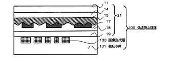
(パッチ転写媒体)本発明のパッチ転写媒体20は、図1に示すように、パッチ21が支持材30の剥離性樹脂層33面へ剥離可能に積層されている。パッチ21は転写材10の転写部をハーフカット処理して、パッチ状としたものである。転写材10は(1)透明基材11と、該透明基材11の一方の面にコレステリック液晶層14、ホログラム形成層15、有色反射性パターン層17、透明反射層18及び接着層19からなり、支持材30は(2)支持基材31へ剥離性樹脂層33を設けてある。
(偽造防止媒体)本発明の偽造防止媒体100は、図2に示すように、本発明の上記パッチ転写媒体20を用いて、転写材10の転写部をハーフカット処理してパッチ状となっているパッチ21を、支持材30から剥離させて、被転写体101へ転写してある。パッチ21は透明基材11、コレステリック液晶層14、ホログラム形成層15、有色反射性パターン層17、透明反射層18及び接着層19からなっている。
パッチ転写媒体20は、次のような効果を奏することができる。
(1)パッチ転写媒体20からパッチ21を被転写体101へ転写する際には、パッチ21はハーフカット処理されているので、容易に支持材30から剥離して、転写性よく転写することができる。
すなわち、通常のスポット転写を実施する場合は、スポット形状を精度よく再現するために、転写工程において、高温・高圧・長時間の転写条件にて転写を行う。例えば、200度以上、5トン/cm2以上、5秒以上等。特に、圧力を強くすることで、スポット形状の端部をはみ出しやぎざぎざのないすっきりしたものに仕上げている。また、この端部をさらにきれいに仕上げるためには、転写する部分の破断強度が小さい方が望ましく、通常の樹脂層であれば数μm以下としている。
しかしながら、コレステリック液晶層がその機能を発揮するには、1.5μm以上を要するため、前記したスポット転写工程による転写は難しく、本発明のようなハーフカット処理が必要となる。
さらに、ホログラム形成層15、有色反射性パターン層17、透明反射層18を加えた層は、さらに破断しにくくなるため、本発明のハーフカット処理が必須となる。
Hereinafter, embodiments of the present invention will be described in detail with reference to the drawings.
(Patch Transfer Medium) In the patch transfer medium 20 of the present invention, as shown in FIG. 1, the
(Anti-Counterfeit Medium) As shown in FIG. 2, the
The patch transfer medium 20 can achieve the following effects.
(1) When the
That is, when normal spot transfer is performed, transfer is performed under high temperature, high pressure, and long time transfer conditions in the transfer process in order to accurately reproduce the spot shape. For example, 200 degrees or more, 5 tons / cm 2 or more, 5 seconds or more. In particular, by increasing the pressure, the end of the spot shape is finished to be clean and free from protrusions and jaggedness. Further, in order to finish this end portion more neatly, it is desirable that the breaking strength of the portion to be transferred is small, and in the case of a normal resin layer, it is set to several μm or less.
However, in order for the cholesteric liquid crystal layer to exhibit its function, 1.5 μm or more is required. Therefore, transfer by the spot transfer process described above is difficult, and half-cut processing as in the present invention is required.
Furthermore, since the layer including the
(2)さらには、このハーフカット処理では、前記した高温・高圧を必要とせず、50度〜150度、0.1〜1トン/cm2、さらには、70度〜100度、0.5トン〜1トン/cm2が好適である。
50度以下・0.1トン/cm2以下では、接着力を確保できず、150度以上・1トン/cm2以上では、コレステリック液晶層にダメージを与える。その中でも、70度〜100度、0.5トン〜1トン/cm2の条件において、安定した接着力とコレステリック液晶層へのダメージの少ない転写を実施することができる。
また、コレステリック液晶層の耐久性を増すため、使用する樹脂層の膜強度を強くしたり、カプセル化した場合には、なおさら、スポット転写が難しくなるため、ハーフカット処理が好適となる。
(ホログラム形成層)
ホログラム形成層15としては、公知のホログラム形成層を用いることができるが、前述のように光選択反射層の色調変化を活かすためには、可視光透過性を有するものが好ましい。例えば、ホログラム形成層は、透明な樹脂素材からなる層の片面にレリーフホログラムの微細凹凸を形成することにより作製することができる。ホログラム形成層を構成するための透明な樹脂材料としては、各種の熱硬化性樹脂、熱可塑性樹脂、電離放射線硬化樹脂等の各種樹脂材料が選択可能である。例えば、熱硬化性樹脂として、不飽和ポリエステル樹脂、アクリルウレタン樹脂、エポキシ変性アクリル樹脂、エポキシ変性不飽和ポリエステル樹脂、アルキッド樹脂、フェノール樹脂等が挙げられる。熱可塑性樹脂としてはアクリル酸エステル樹脂、アクリルアミド樹脂、ニトロセルロース樹脂、ポリスチレン樹脂等が挙げられる。これらの樹脂は単独、または2種類以上の共重合体として使用することができる。また、これらの樹脂は単独、または2種類以上を各種イソシアネート樹脂や、ネフテン酸コバルト、ナフテン酸亜鉛等の金属石鹸ベンゾイルパーオキサイド、メチルエチルケトンパーオキサイド等の過酸化物、ベンゾフェノン、アセトフェノン、アントラキノン、ナフトキノン、アゾビスイソブチロニトリル、ジフェニルスルフィド等の熱または紫外線硬化剤を配合してもよい。また、電離放射線硬化型樹脂としては、エポキシアクリレート、ウレタンアクリレート、アクリル変性ポリエステル等が挙げられる。このような電離放射線硬化型樹脂に架橋構造、粘度調整等を目的として、他の単官能または多官能モノマー、オリゴマー等を抱合させることができる。
(2) Furthermore, in this half-cut treatment, the above-described high temperature and high pressure are not required, and 50 to 150 degrees, 0.1 to 1 ton / cm 2 , and 70 to 100 degrees, 0.5 Tons to 1 ton / cm 2 is preferred.
If it is 50 degrees or less and 0.1 ton / cm 2 or less, the adhesive force cannot be secured, and if it is 150 degrees or more and 1 ton / cm 2 or more, the cholesteric liquid crystal layer is damaged. Among these, stable adhesion and transfer with little damage to the cholesteric liquid crystal layer can be performed under the conditions of 70 to 100 degrees and 0.5 to 1 ton / cm 2 .
Further, in order to increase the durability of the cholesteric liquid crystal layer, when the film strength of the resin layer to be used is increased or encapsulated, spot transfer becomes more difficult, and half-cut processing is preferable.
(Hologram forming layer)
As the
ホログラム形成層15は、感光性樹脂材料にホログラムの干渉露光を行って現像することによって直接的に形成することもできるが、予め作製したレリーフホログラムもしくはその複製物、またはそれらのメッキ型等を複製用型として用い、その型面を上記の樹脂材料に押し付けることにより、賦型を行うこともできる。熱硬化性樹脂や電離放射線硬化性樹脂を用いる場合には、型面に未硬化の樹脂を密着させたまま、加熱または電離放射線照射により硬化を行い、硬化後に剥離することによって、硬化した透明な樹脂材料からなる層の片面にレリーフホログラムの微細凹凸を形成することができる。なお、本発明では、同様な方法によりパターン状に形成して模様状とした回折格子を有する回折格子形成層もホログラム形成層に含めるものとする。また、ホログラム形成層および回折格子形成層を合せたものも含める。
前記電離放射線硬化性樹脂としては、好ましくは、(1)分子中にイソシアネート基を3個以上有するイソシアネート類、(2)分子中に水酸基を少なくとも1個と(メタ)アクリロイルオキシ基を少なくとも2個有する多官能(メタ)アクリレート類、又は(3)分子中に水酸基を少なくとも2個有する多価アルコール類の反応生成物であるウレタン(メ
タ)アクリレートオリゴマーを含有する電離放射線硬化性樹脂を用い、好ましくはポリエチレンワックスを含ませて、塗布し乾燥して電離放射線で硬化させて、電離放射線硬化樹脂とすればよい。
前記ウレタン(メタ)アクリレートオリゴマーを含有する電離放射線硬化性樹脂は、ウレタン(メタ)アクリレートオリゴマーを含有する電離放射線硬化性樹脂の硬化物、具体的には、特開2001−329031号公報で開示されている光硬化性樹脂などが例示できる。具体的には、MHX405ニス(ザ・インクテック(株)製、電離放射線硬化性樹脂商品名)が例示できる。
The
The ionizing radiation curable resin is preferably (1) an isocyanate having three or more isocyanate groups in the molecule, and (2) at least one hydroxyl group and at least two (meth) acryloyloxy groups in the molecule. Preferably using an ionizing radiation curable resin containing a polyfunctional (meth) acrylate having, or (3) a urethane (meth) acrylate oligomer which is a reaction product of a polyhydric alcohol having at least two hydroxyl groups in the molecule. May contain polyethylene wax, applied, dried, and cured with ionizing radiation to form an ionizing radiation curable resin.
The ionizing radiation curable resin containing the urethane (meth) acrylate oligomer is disclosed in a cured product of an ionizing radiation curable resin containing a urethane (meth) acrylate oligomer, specifically, JP-A-2001-329031. The photocurable resin etc. which can be illustrated. Specifically, MHX405 varnish (product name of ionizing radiation curable resin, manufactured by The Inktec Co., Ltd.) can be exemplified.
(ホログラム形成層の形成)ホログラム形成層15の形成は、上記の電離放射線硬化性樹脂を主成分とし、光重合開始剤、可塑剤、安定剤、界面活性剤等を加え、溶媒へ分散または溶解して、ロールコート、グラビアコート、コンマコート、ダイコートなどの公知のコーティング方法で塗布し乾燥して、ホログラム(レリーフ)を賦型後に電離放射線で反応(硬化)させればよい。ホログラム形成層15の厚さは、通常、1〜10μm程度、好ましくは2〜5μmである。
(ホログラム)次に、ホログラム形成層15の表面には、ホログラムなどの光回折効果の発現する所定の微細な凹凸(レリーフ構造)を賦型し、硬化させる。ホログラムは物体光と参照光との光の干渉による干渉縞を凹凸のレリーフ形状で記録されたもので、例えば、フレネルホログラム等のレーザ再生ホログラム、及びレインボーホログラム等の白色光再生
ホログラム、さらに、それらの原理を利用したカラーホログラム、コンピュータジェネレーティッドホログラム(CGH)、ホログラフィック回折格子などがある。
(Formation of hologram forming layer) The formation of the
(Hologram) Next, on the surface of the
ホログラム形成層15面へ、レリーフ形状を賦形(複製ともいう)する。ホログラムの賦型は、公知の方法によって形成でき、例えば、回折格子やホログラムの干渉縞を表面凹凸のレリーフとして記録する場合には、回折格子や干渉縞が凹凸の形で記録された原版をプレス型(スタンパという)として用い、上記樹脂層上に前記原版を重ねて加熱ロールなどの適宜手段により、両者を加熱圧着することにより、原版の凹凸模様を複製することができる。
この方法を用いて、コレステリック液晶層14にも同様のレリーフ形状を形成することができる。この場合は、コレステリック液晶層に入射した光がコレステリック液晶層と接着層との界面で反射するとき、この界面そのものが前記レリーフ形状を有していることから、この界面での反射そのものが、ホログラム効果を生み出すことになる。
したがって、この界面で反射する場合は、この反射光はまだコレステリック液晶層をでていない、すなわち、コレステリック液晶層内で反射する光の一部である。(コレステリック液晶層が右円偏光を反射する場合には、ホログラムを形成する光も右円偏光性を有していることになる。
これに対して、ホログラム形成層に設けているホログラムレリーフで反射する場合には、コレステリック液晶層に入射した光は、一旦コレステリック液晶層を通過しており、その後、その層に接して形成されているホログラム形成層も通過する時、ホログラム形成層と接着層の界面(レリーフ形状)で反射されることになる。したがって、コレステリック液晶層が右円偏光を反射する場合には、このホログラムを形成する光は、左円偏光性を有することになる。
これらの円偏光性の違いを利用して、偽造防止媒体を観察する際に右ないしは左円偏光フィルムを用いて確認することにより、その真正性を簡便な方法で認証することができる。
A relief shape is formed (also referred to as replication) on the surface of the
Using this method, a similar relief shape can be formed in the cholesteric
Therefore, when the light is reflected at this interface, the reflected light has not yet appeared on the cholesteric liquid crystal layer, that is, part of the light reflected within the cholesteric liquid crystal layer. (When the cholesteric liquid crystal layer reflects right circularly polarized light, the light forming the hologram also has right circular polarization.
On the other hand, when the light is reflected by the hologram relief provided in the hologram forming layer, the light incident on the cholesteric liquid crystal layer once passes through the cholesteric liquid crystal layer and is then formed in contact with the layer. When passing through the hologram forming layer, it is reflected at the interface (relief shape) between the hologram forming layer and the adhesive layer. Therefore, when the cholesteric liquid crystal layer reflects right circularly polarized light, the light forming this hologram has left circular polarization.
By utilizing these differences in circular polarization properties and confirming with a right or left circularly polarizing film when observing the anti-counterfeit medium, the authenticity can be authenticated by a simple method.
また、ホログラム形成層15に形成するホログラムパターンは単独でも、複数でもよい。ホログラム形成層15は、スタンパでエンボス中、又はエンボス後に、電離放射線を照射して、電離放射線硬化性樹脂を硬化させる。上記の電離放射線硬化性樹脂は、レリーフを形成後に、紫外線や電子線などの電離放射線を照射して硬化(反応)させると電離放射線硬化樹
脂(微細な凹凸=レリーフ構造=ホログラム)となる。この方法は、比較的低温・低圧力下で賦形できるため、コレステリック液晶層14へのダメージを少なくすることができる。
さらに、ホログラムレリーフもしくは、ホログラム形成層15は、コレステリック液晶層14に対して、観察側に設けてもよい。この場合は、ホログラムを形成する光は、コレステリック液晶層14の偏光性の影響を受けない。さらに、コレステリック液晶層14とホログラム形成層15の間に透明フィルムを設けてもよい。
Further, the hologram pattern formed on the
Further, the hologram relief or
また、偽造防止媒体100は、次のような効果を奏することができる。
(1)偽造防止媒体100の最表面は、パッチ21の透明基材11となり、前記透明基材11は一旦フィルム用に高強度に成膜されたものであので、多数回の繰り返し使用でも、耐擦傷性や耐溶剤性などの耐久性に優れ、従来の塗布された樹脂による保護層に比較して、媒体の表面を強固に保護することができる。前記透明基材11としては、2軸延伸されたフィルムが好ましいが、さらに、コレステリック液晶層14の円偏光性を円偏光フィルムによって確認するために、位相差がないフィルムが最も望ましい。
(2)特に、熱溶融転写方式、熱昇華転写方式又はインクジェット方式のいずれかで情報が印字された画像が形成してある被転写体では画像形成層103が最表面となってしまい、特に外力、溶媒、熱などに対して耐久性が低いが、画像形成層103面に耐久性の高いフィルムを有するパッチ21が保護するので、過酷な使用条件においても、画像形成層103の画像を、強固に保護することができる。
(3)かつ、偽造防止媒体100は、コレステリック液晶層14を含むパッチ21が、位置精度よく転写されるので、被転写体101上にあらかじめ設けられている画像等の情報と、パッチ21に形成された画像とを組み合わせることができ、且つ、パッチ21に形成された画像は、偏光フィルムを使用して観察することで、パッチ21に形成した画像のみを遮断したり、透過したりして、その真正性を確認することを可能とし、さらに偽造防止性を高めることができる。もちろん、光学的に自動読み取りする場合にも同様の効果を発現する。
Moreover, the
(1) The outermost surface of the
(2) In particular, the image forming layer 103 is the outermost surface of the transfer target on which an image on which information is printed is formed by any one of the hot melt transfer method, the heat sublimation transfer method, and the ink jet method. The
(3) Since the
(転写材)転写材10は透明基材11、前記透明基材11の一方の面にコレステリック液晶層14、ホログラム形成層15、有色反射性パターン層17、透明反射層18及び接着層19からなっている。
(透明基材)透明基材11としては、ハーフカット処理された部分を境界にして、透明基材11部が切断され、少なくとも画像形成層103を含む部分を覆う形態で、保護層として機能する。透明性と、耐候性、耐摩擦性、耐薬品性等の耐久性を有するものであれば、用途に応じて種々の材料が適用できる。例えば、ポリエチレンテレフタレート、ポリエチレンナフタレートなどのポリエステル系樹脂、ポリアミド系樹脂、ポリ塩化ビニルなどのビニル系樹脂、アクリル系樹脂、イミド系樹脂、ポリアリレートなどのエンジニアリング樹脂、ポリカーボネート、環状ポリオレフィン系樹脂、セロファンなどのセルロース系フィルムなどが例示できる。前記透明基材11は、これら樹脂を主成分とする共重合樹脂、または、混合体(アロイでを含む)、若しくは複数層からなる積層体であっても良い。特にTACフィルム(トリアセチルセルロース)は光学的特性に優れ(位相差がなく)好適である。
また、前記透明基材11は、延伸又は未延伸のフィルムでも良いが、強度を向上させる目的で、一軸方向または二軸方向に延伸したフィルムが好ましい。厚は、通常2.5〜50μm程度が適用できるが、2.5〜25μmが好適である。前記透明基材11は、塗布に先立って塗布面へ、コロナ放電処理、プラズマ処理、プライマー(アンカーコート、接着促進剤、易接着剤とも呼ばれる)塗布処理、アルカリ処理、などの易接着処理を行ってもよい。また、必要に応じて、充填剤、可塑剤、着色剤、帯電防止剤などの添加剤を加えてもよい。2軸延伸ポリエチレンテレフタレートのフィルムが、耐熱性、機械的強度がよいため好適に使用される。
(Transfer Material) The transfer material 10 comprises a
(Transparent base material) The
The
(コレステリック液晶層)
コレステリック液晶層14は、観察側からの入射光に対して左円偏光もしくは右円偏光のいずれか一方を反射する光選択反射性を有するもの。また、これらのものを組み合わせて適用して、判定方法を複雑なものとし、より高度な真正性識別体とすることもできる。
コレステリック液晶としては、コレステロールのハロゲン化物、モノカルボン酸コレステロールエステル、モノカルボン酸シトステロールエステル、安息香酸誘導体のコレスタノールエステル、二塩基酸ジコレステリルエステル、主鎖型液晶高分子化合物、側鎖型液晶高分子化合物、剛直主鎖型液晶高分子化合物などが挙げられる。
より具体的には、例えばコレステリルクロライド、コレステリルアセテート、コレステリルノナノエート、炭酸メチルコレステロール、炭酸エチルコレステロール、コレステリルp−メトキシベンゾエート、シトステロイルベンゾエート、シトステロイルp−メチルベンゾエート、コレスタニルベンゾエート、10、12−ドコサジインジカルボン酸ジコレステリルエステル、8、12−エイコサジカルボン酸ジコレステリルエステル、10、12−ペンタコサジインジカルボン酸ジコレステリルエステル、ドデカジカルボン酸ジコレステリルエステル、12、14−ヘキサコサジインジカルボン酸ジコレステリルエステル、4−(7−コレステリルオキシカルボニルヘプチルオキシ)フェノキシオクタン酸コレステリルエステル、L−グルタミン酸−γ−ベンジル/L−グルタミン酸−γ−ドデシル共重合体などがある。
さらに、コレステリルホルメート、コレステリルアセテート、コレステリルプロピオネート、コレステリルブチレート、コレステリルペンタネート、コレステリルヘキサネート、コレステリルヘプタネート、コレステリルオクタネート、コレステリルノナノエート、コレステリルデカネート、コレステリルドデカネート(コレステリルラウレート)、コレステリルミリステート、コレステリルパルミテート、コレステリルステアレート、コレステリルオレエート、コレステリルオレイルカーボネート、コレステリルリノレート、コレステリル12−ヒドロキシステアレート、コレステリルメルカプタン、コレステロールクロライド、コレステリルフルオライド、コレステリルブロマイド、コレステリルアイオダイド等を挙げることができる。
好ましくは、アルキルコレステロール(例えばコレステロールナノエート)およびコレステリルハライド(例えばコレステロールクロライド)コレステリルオレイルカーボネート3種の混合物が挙げられ、これらの3つのタイプの液晶は常温で使用できるように混合して用いられるのが一般的である。
尚、ここに示す化合物に限定されるものではなく、またこれらのコレステリック液晶化合物は、1種または2種以上混合して用いることができる。
(Cholesteric liquid crystal layer)
The cholesteric
Cholesteric liquid crystals include cholesterol halides, monocarboxylic acid cholesterol esters, monocarboxylic acid sitosterol esters, benzoic acid derivative cholestanol esters, dibasic acid dicholesteryl esters, main chain liquid crystal polymer compounds, side chain liquid crystal polymers Examples thereof include molecular compounds and rigid main chain type liquid crystal polymer compounds.
More specifically, for example, cholesteryl chloride, cholesteryl acetate, cholesteryl nonanoate, methyl carbonate, ethyl cholesterol, cholesteryl p-methoxybenzoate, sitosteroyl benzoate, sitosteroyl p-methyl benzoate, cholestanyl benzoate, 10, 12- Docosadiin dicarboxylic acid dicholesteryl ester, 8,12-eicosadicarboxylic acid dicholesteryl ester, 10,12-pentacosadiin dicarboxylic acid dicholesteryl ester, dodecadicarboxylic acid dicholesteryl ester, 12,14-hexacosadiin dicarboxylic acid Dicholesteryl ester, 4- (7-cholesteryloxycarbonylheptyloxy) phenoxyoctanoic acid cholesteryl ester, L-glu Min acid -γ- benzyl / L-glutamate -γ- dodecyl copolymers and the like.
Further, cholesteryl formate, cholesteryl acetate, cholesteryl propionate, cholesteryl butyrate, cholesteryl pentanate, cholesteryl hexanate, cholesteryl heptanoate, cholesteryl octanate, cholesteryl nonanoate, cholesteryl decanate, cholesteryl decanate (cholesteryl laurate) Cholesteryl myristate, cholesteryl palmitate, cholesteryl stearate, cholesteryl oleate, cholesteryl oleyl carbonate, cholesteryl linoleate, cholesteryl 12-hydroxystearate, cholesteryl mercaptan, cholesterol chloride, cholesteryl fluoride, cholesteryl bromide, cholesteryl iodide, etc. Can be mentioned.
Preferably, a mixture of three kinds of alkylcholesterol (for example, cholesterol nanoate) and cholesteryl halide (for example, cholesterol chloride) cholesteryl oleyl carbonate is used, and these three types of liquid crystals are used so as to be used at room temperature. Is common.
In addition, it is not limited to the compound shown here, Moreover, these cholesteric liquid crystal compounds can be used 1 type or in mixture of 2 or more types.
ネマチック液晶化合物にカイラル化合物を加えてコレステリック液晶とするものとしては、液晶化合物として、4−置換安息香酸4’−置換フェニルエステル、4−置換シクロヘキサンカルボン酸4’−置換フェニルエステル、4−置換シクロヘキサンカルボン酸4’−置換ビフェニルエステル、4−(4−置換シクロヘキサンカルボニルオキシ)安息香酸4’−置換フェニルエステル、4−(4−置換シクロヘキシル)安息香酸4’−置換フェニルエステル、4−(4−置換シクロヘキシル)安息香酸4’−置換シクロヘキシルエステル、4−置換4’−置換ビフェニル、4−置換フェニル4’−置換シクロヘキサン、4’−置換シクロヘキサン、2−(4−置換フェニル)−5−置換ピリジン等、が用いられる。
特に好ましくは、少なくとも分子の一方の末端にシアノ基又はフッ素原子を有する液晶化合物を用い、これらの液晶化合物にそれぞれ好適な各種のカイラル剤を加えたものが用いられる。カイラル化合物としては、「CB−15」、「C−15」(以上、BDH社製)、「CM−21」、「CM−22」、「CM−19」、「CM−20」、「CM」(以上、チッソ社製)、「S1082」、「S−811」、「R−811」(以上、メルク社製)、等を挙げることができる。
As a liquid crystal compound in which a chiral compound is added to a nematic liquid crystal compound to form a cholesteric liquid crystal, 4-substituted benzoic acid 4′-substituted phenyl ester, 4-substituted cyclohexanecarboxylic acid 4′-substituted phenyl ester, 4-substituted cyclohexane Carboxylic acid 4′-substituted biphenyl ester, 4- (4-substituted cyclohexanecarbonyloxy) benzoic acid 4′-substituted phenyl ester, 4- (4-substituted cyclohexyl) benzoic acid 4′-substituted phenyl ester, 4- (4- Substituted cyclohexyl) benzoic acid 4'-substituted cyclohexyl ester, 4-substituted 4'-substituted biphenyl, 4-substituted phenyl 4'-substituted cyclohexane, 4'-substituted cyclohexane, 2- (4-substituted phenyl) -5-substituted pyridine Etc. are used.
Particularly preferably, a liquid crystal compound having a cyano group or a fluorine atom at least at one end of the molecule is used, and various suitable chiral agents are added to these liquid crystal compounds. As the chiral compound, “CB-15”, “C-15” (manufactured by BDH), “CM-21”, “CM-22”, “CM-19”, “CM-20”, “CM” (Above, manufactured by Chisso Corporation), "S1082", "S-811", "R-811" (above, manufactured by Merck & Co., Inc.), and the like.
さらに、三次元架橋可能な液晶性の重合性モノマー分子または重合性オリゴマー分子を用いることができる。所定の重合性モノマー分子または重合性オリゴマー分子に任意のカイラル剤を添加することにより、コレステリック型液晶分子を含む層を得ることができる。
三次元架橋可能なモノマー分子としては、例えば特開平7−258638号公報や特表
平10−508882号公報で開示されているような、液晶性モノマーおよびキラル化合
物の混合物がある。より具体的な例を示すと、例えば下記一般化学式(1)〜(11)に
示されるような液晶性モノマーを用いることができる。尚、一般化学式(11)で示され
る液晶性モノマーの場合、Xは2〜5の範囲の整数であることが望ましい。
Furthermore, a three-dimensionally crosslinkable liquid crystalline polymerizable monomer molecule or polymerizable oligomer molecule can be used. A layer containing cholesteric liquid crystal molecules can be obtained by adding an arbitrary chiral agent to a predetermined polymerizable monomer molecule or polymerizable oligomer molecule.
Examples of the three-dimensionally crosslinkable monomer molecule include a mixture of a liquid crystal monomer and a chiral compound as disclosed in, for example, JP-A-7-258638 and JP-T-10-508882. As a more specific example, for example, liquid crystalline monomers represented by the following general chemical formulas (1) to (11) can be used. In the case of the liquid crystalline monomer represented by the general chemical formula (11), X is preferably an integer in the range of 2 to 5.

また、カイラル剤としては、例えば下記一般化学式(12)〜(14)に示されるよう
なカイラル剤を用いることができる。尚、一般化学式(12)、(13)で示されるカイ
ラル剤の場合、Xは2〜12の範囲の整数であることが望ましく、また、一般化学式(1
4)で示されるカイラル剤の場合、Xが2〜5の範囲の整数であることが望ましい。
Moreover, as a chiral agent, a chiral agent as shown, for example by the following general chemical formula (12)-(14) can be used. In the case of the chiral agent represented by the general chemical formulas (12) and (13), X is preferably an integer in the range of 2 to 12, and the general chemical formula (1
In the case of the chiral agent represented by 4), X is preferably an integer in the range of 2-5.
また、オリゴマー分子を用いる場合は、例えば特開昭57−165480号公報で開示
されているようなコレステリック相を有する環式オルガノポリシロキサン化合物を用いる
ことができる。例えば、重合性モノマー分子または重合性オリゴマー分子に、カイラル剤
を数%〜10%程度添加することによりコレステリック液晶層を得ることができる。コレ
ステリック液晶層は、ほぼ均一な厚みを有する層として形成することができるが、層の有
無や厚みの違いによりパターンが形成されたパターン層とすることもできる。パターン層
は、各種印刷方法を用いて形成することができる。
When oligomer molecules are used, a cyclic organopolysiloxane compound having a cholesteric phase as disclosed in, for example, JP-A-57-165480 can be used. For example, a cholesteric liquid crystal layer can be obtained by adding about several to 10% of a chiral agent to polymerizable monomer molecules or polymerizable oligomer molecules. The cholesteric liquid crystal layer can be formed as a layer having a substantially uniform thickness, but can also be a pattern layer in which a pattern is formed depending on the presence or absence of the layer or a difference in thickness. The pattern layer can be formed using various printing methods.
また、有機合成によって得られるネマチック液晶の末端基に不斉炭素を有する基を導入したコレステロール基を持たないコレステリック液晶や、コレステロール誘導体にシッフ系ネマチック液晶を加えた混合液晶も用いられる。さらには、天然コレステロールのハロゲン置換物、エステル化物(コレステリルベンゾエート、コレステリルクロライド、コレステリルオリエート、コレステリルノナノエート等も好適である。
これらのコレステリック液晶を設ける方法としては、コレステリック液晶材料を適当な溶媒に溶解し、各種の印刷方法によって適用し、乾燥させることによって形成することができる。このとき、重合性のコレステリック液晶を用いて紫外線重合性組成物を調製し、得られた紫外線重合性組成物を各種の印刷法によって適用し、乾燥後に紫外線を照射して重合させて形成することもできる。
また液晶をゼラチン他樹脂膜等でカプセル化したインキを用いて形成してもよい。カプセル化したものは、その製造時の作業性だけでなく、物理特性(強靭性、耐摩耗性、耐熱性等)に優れるとともに、衛生面等で特に好適である。
Further, a cholesteric liquid crystal having no cholesterol group in which a group having an asymmetric carbon is introduced into a terminal group of a nematic liquid crystal obtained by organic synthesis, or a mixed liquid crystal in which a Schiff nematic liquid crystal is added to a cholesterol derivative is also used. Furthermore, halogen substitution products and esterified products of natural cholesterol (cholesteryl benzoate, cholesteryl chloride, cholesteryl oleate, cholesteryl nonanoate, and the like are also suitable.
As a method of providing these cholesteric liquid crystals, it can be formed by dissolving a cholesteric liquid crystal material in an appropriate solvent, applying it by various printing methods, and drying it. At this time, an ultraviolet-polymerizable composition is prepared using a polymerizable cholesteric liquid crystal, and the obtained ultraviolet-polymerizable composition is applied by various printing methods, and after drying, it is polymerized by irradiation with ultraviolet rays. You can also.
Alternatively, the liquid crystal may be formed using an ink encapsulated with a resin film such as gelatin. The encapsulated product is excellent not only in workability during production but also in physical properties (toughness, wear resistance, heat resistance, etc.) and particularly suitable in terms of hygiene.
コレステリック液晶層14の形状、厚さは、真正性識別体の使用目的に応じて適宜最適なものとする必要がある。選択的反射性や、偏光性を維持した上で、個々に対応した厚さ、すなわち1.5μm〜50μmのうち、最適なものとする。1μm以下であれば、その選択的反射性や、偏光性が不十分であり、50μm以上とすると、ハーフカット処理がし難くなる上、パッチ転写後の被転写体101上の突出が大きいものなり、使用時に引っかかり、剥がれる等のトラブルの原因となる。
上記コレステリック液晶層14を設ける際、予め以下の配向膜を設ける等の配向処理を施しても良い。配向膜は、ポリビニルアルコール樹脂(PVA)、ポリイミド樹脂等の一般に配向膜として使用し得るものであれば、いずれでもよい。配向膜は、これらの樹脂の溶剤溶液を、コレステリック液晶層14を形成する層の表面に適宜な塗布法により塗布し、乾燥させた後に、布、ブラシ等を用いて摩擦するラビングを行なって形成する。
The shape and thickness of the cholesteric
When the cholesteric
(接着層)接着層19としては、公知の加熱されると溶融または軟化して接着効果を発揮する感熱接着剤が適用でき、具体的には、塩化ビニル系樹脂、酢酸ビニル系樹脂、塩化ビニル酢酸ビニル共重合樹脂、アクリル系樹脂、ポリエステル系樹脂などが挙げられる。
(粘着性接着層)接着層19としては、 好ましくは、熱接着性と共に、粘着性をも有する粘着性接着層である。粘着性接着層としては、粘着性と熱接着性を有するアクリル系樹脂やゴム系樹脂、又は粘着性樹脂と熱接着性樹脂との混合物などが適用できる。
粘着性樹脂としては、酢酸ビニル樹脂、酢酪酸ビニル樹脂、クロロプレンゴム、イソプレンゴム、ウレタン樹脂等がある。
(Adhesive layer) As the
(Adhesive adhesive layer) The
Examples of the adhesive resin include vinyl acetate resin, vinyl acetate butyrate resin, chloroprene rubber, isoprene rubber, and urethane resin.
該材料樹脂を溶剤に溶解または分散させて、適宜顔料などの添加剤を添加して、公知のロールコーティング、グラビアコーティング、コンマコーティングなどの方法で塗布し乾燥させて、厚さ1〜30μmの層を得る。被転写体101の表面がフィルムシートの様に平滑な場合は、1〜5μmの厚さが好適だが、画像形成面では、3μm以上あることが好ましい。逆に、被転写体101の表面が、紙や布のように30μm以上の表面粗さを持つ場合には、接着層19の厚さとしては、5μm〜30μmの厚さ、さらには、20μm〜30μmの厚さが好適となる。特に、粘着性接着層である場合には、画像形成部以外の部分の樹脂が、被転写体101内に入り込んでいくため、厚い方が望ましい。
ただし、パッチとして、透明基材を有していることは、接着層19が、被転写体101内に入り込むことを必要とせず、部分的に接着しているだけで十分な耐久性を発揮する。
The material resin is dissolved or dispersed in a solvent, an additive such as a pigment is added as appropriate, and the layer is applied and dried by a known method such as roll coating, gravure coating, or comma coating, and a layer having a thickness of 1 to 30 μm Get. When the surface of the transfer target 101 is as smooth as a film sheet, a thickness of 1 to 5 μm is suitable, but it is preferably 3 μm or more on the image forming surface. On the contrary, when the surface of the transfer target 101 has a surface roughness of 30 μm or more like paper or cloth, the thickness of the
However, having a transparent base material as a patch does not require the
(支持材)支持材30は支持基材31へ剥離性樹脂層33が設けられている。
(支持基材)支持基材31としては、特に限定されず、例えば、コンデンサーペーパー、グラシン紙、硫酸紙、またはサイズ度の高い紙、合成紙(ポリオレフィン系、ポリスチレン系)、上質紙、コート紙、合成樹脂またはエマルジョン含浸紙、あるいは、ポリエチレンテレフタレート、ポリブチレンテレフタレート、ポリエチレンナフタレートなどのポリエステル系樹脂、ポリアミド系樹脂、ポリ塩化ビニルなどのビニル系樹脂、アクリル系樹脂、イミド系樹脂、ポリアリレートなどのエンジニアリング樹脂、ポリカーボネート、環状ポリオレフィン系樹脂、セロファンなどのセルロース系フィルムなどのフィルムが例示できる。上記の支持基材31上に後述さる剥離性樹脂層33を設ける際に、接着性を向上させるために、支持基材31表面をコロナ放電処理したり、プライマー層を設けてもよい。
支持材30は10μm〜100μmの厚みのものが好ましく、シート基材が薄すぎると得られるパッチ転写媒体20のいわゆるコシがなくなり、熱転写プリンターで搬送できなかったり、パッチ転写媒体20にカールやシワが発生したりする。一方、支持材30が厚すぎると、得られるパッチ転写媒体20が厚くなりすぎ、熱転写プリンタで搬送駆動させる力が大きくなりすぎて、熱転写プリンタに故障が生じたり、正常に搬送できなかったりする。
(剥離性樹脂層)剥離性樹脂層33としては、粘着剤層や簡易接着層やエクストルージョンコーティング(EC)層により形成する。
(Support Material) The support material 30 is provided with a peelable resin layer 33 on a support base material 31.
(Supporting base material) The supporting base material 31 is not particularly limited. For example, condenser paper, glassine paper, sulfuric acid paper, high-size paper, synthetic paper (polyolefin-based, polystyrene-based), high-quality paper, coated paper , Synthetic resin or emulsion-impregnated paper, polyester resins such as polyethylene terephthalate, polybutylene terephthalate, polyethylene naphthalate, polyamide resins, vinyl resins such as polyvinyl chloride, acrylic resins, imide resins, polyarylate, etc. Examples include engineering resins, polycarbonates, cyclic polyolefin resins, and cellulose films such as cellophane. When the peelable resin layer 33 described later is provided on the support base 31, the surface of the support base 31 may be subjected to corona discharge treatment or a primer layer may be provided in order to improve adhesion.
The support material 30 preferably has a thickness of 10 μm to 100 μm. If the sheet base material is too thin, the so-called stiffness of the obtained patch transfer medium 20 is lost, and it cannot be conveyed by a thermal transfer printer, or the patch transfer medium 20 is curled or wrinkled. Occur. On the other hand, if the support material 30 is too thick, the resulting patch transfer medium 20 becomes too thick, and the force to drive and drive the thermal transfer printer becomes too great, causing the thermal transfer printer to fail or not be transported normally.
(Peelable resin layer) The peelable resin layer 33 is formed of a pressure-sensitive adhesive layer, a simple adhesive layer, or an extrusion coating (EC) layer.
粘着剤層は、従来公知の溶剤系及び水系のいずれの粘着剤、例えば、酢酸ビニル樹脂、アクリル樹脂、酢酸ビニル−アクリル共重合体、酢酸ビニル−塩化ビニル共重合体、エチレン−酢酸ビニル共重合体、ポリウレタン樹脂や、天然ゴム、クロロプレンゴムなどのゴム系樹脂などが挙げられる。粘着剤層の塗工量は、約8〜30g/m2(固形分)が一般的であり、従来公知の方法、すなわち、グラビアコート、ロールコート、コンマコート等の方法で、塗布し乾燥して粘着剤層を形成する。また、粘着剤層の粘着力は、透明基材11と粘着剤層との剥離強度で、JIS Z0237準拠の180°による剥離方法において、5〜1,000g程度の範囲にすることが望ましい。以上の如き粘着剤の種類や、塗工量は、前記支持基材31上に粘着剤層を形成する際に、その剥離強度が前記範囲になるように、選択して使用することが好ましい。また、支持基材31上に粘着剤層を設け、透明基材11と粘着剤層を積層するには、粘着剤層のドライラミネーションやホットメルトラミネーション等の方法が採用できる。
The pressure-sensitive adhesive layer is a conventionally known solvent-based or water-based pressure-sensitive adhesive, such as vinyl acetate resin, acrylic resin, vinyl acetate-acrylic copolymer, vinyl acetate-vinyl chloride copolymer, ethylene-vinyl acetate copolymer. Examples thereof include rubber resins such as coalescence, polyurethane resin, natural rubber, and chloroprene rubber. The coating amount of the pressure-sensitive adhesive layer is generally about 8 to 30 g / m 2 (solid content), and is applied and dried by a conventionally known method such as gravure coating, roll coating, comma coating, and the like. To form an adhesive layer. Further, the adhesive strength of the pressure-sensitive adhesive layer is the peel strength between the
簡易接着層は、スチレン−ブタジエン共重合ゴム(SBR)、アクリロニトリル−ブタジエン共重合ゴム(NBR)やポリアクリル酸エステル等のアクリル系樹脂のラテックスや、ゴム系レジン、ワックス類及びそれらの混合物を用いて、支持基材31上に従来公知の塗工方式で形成し、透明基材11と簡易接着層とを加熱しながらドライラミネーションして積層すればよい。そして、透明基材11と支持基材31を剥がした後の簡易接着層は、粘着性が低下し、再度、透明基材11と支持基材31を貼り合わせることはできない。このような簡易接着層を用いる場合、支持基材31と簡易接着層との間にプライマー層を設けてもよい。
The simple adhesive layer uses styrene-butadiene copolymer rubber (SBR), acrylonitrile-butadiene copolymer rubber (NBR), latex of acrylic resins such as polyacrylic acid esters, rubber resins, waxes and mixtures thereof. Then, it may be formed on the support substrate 31 by a conventionally known coating method, and the
また、剥離性樹脂層33として、支持基材31上にEC層で設けてもよい。EC層を形成する熱可塑性樹脂は透明基材11には本質的に接着せず、EC加工特性のある樹脂であれば特に限定されないが、透明基材11に一般的に利用されるPETフィルムに対して、本質的な接着性を有さず加工性も優れる、ポリオレフィン系樹脂が特に好ましい。具体的には、LDPE、MDPE、HDPE、PP樹脂等を使用できる。
これらの樹脂をEC加工する際の冷却ロールをマットロールを使用して、EC層表面にマット面が転写されて凹凸形状を賦形して不透明としたり、ポリオレフィン系樹脂に炭酸カルシウム、酸化チタン等の白色顔料を練り混んで、不透明としたり、してもよい。
また、該EC層は単層でも、複数層でもよい。透明基材11からの剥離強度は、EC加工時の加工温度、樹脂種によって調整することができる。このように、支持基材31上にEC層をEC加工と同時に、いわゆるECラミネーションで支持基材31と透明基材11をEC層を介して積層させればよい。
Further, as the peelable resin layer 33, an EC layer may be provided on the support base 31. The thermoplastic resin forming the EC layer does not essentially adhere to the
Using a mat roll as the cooling roll for EC processing of these resins, the mat surface is transferred to the surface of the EC layer to make the irregular shape opaque, and the polyolefin resin is calcium carbonate, titanium oxide, etc. The white pigment may be kneaded and made opaque.
The EC layer may be a single layer or a plurality of layers. The peel strength from the
(耐熱滑性層)パッチ転写媒体20では、必要に応じて、支持基材31の剥離性樹脂層33面と反対面に耐熱滑性層を設けてもよい。
パッチ転写媒体20を用いて被転写体101へ再転写はサーマルヘッドやヒートロール等の熱転写プリンターが用いられるので、その熱によるスティッキングやシワなどの悪影響を防止するため、耐熱滑性層を設けてもよい。耐熱滑性層を形成する樹脂としては、従来公知のものであればよく、例えば、ポリビニルブチラール樹脂、ポリビニルアセトアセタール樹脂、アクリル系樹脂、セルロース系樹脂、芳香族ポリアミド樹脂、ポリイミド樹脂、ポリカーボネート樹脂等が挙げられる。
また、耐熱滑性層に添加、又は上塗りする滑り性付与剤としては、例えば、ポリアルコール高分子化合物とポリイソシアネート化合物及び燐酸エステル系化合物からなる層であり、更に充填剤を添加することがより好ましい。耐熱滑性層は、上記に記載した樹脂、滑り性付与剤、更に充填剤を、適当な溶剤により、溶解又は分散させて、支持基材31の背面に、例えば、グラビア印刷法、スクリーン印刷法等で塗布し乾燥して形成すればよい。
(Heat resistant slipping layer) In the patch transfer medium 20, a heat resistant slipping layer may be provided on the surface opposite to the peelable resin layer 33 surface of the support base 31 as required.
Since retransfer to the transfer target 101 using the patch transfer medium 20 is performed using a thermal transfer printer such as a thermal head or a heat roll, a heat resistant slipping layer is provided to prevent adverse effects such as sticking and wrinkles due to heat. Also good. The resin for forming the heat resistant slipping layer may be any conventionally known resin, such as polyvinyl butyral resin, polyvinyl acetoacetal resin, acrylic resin, cellulose resin, aromatic polyamide resin, polyimide resin, polycarbonate resin, etc. Is mentioned.
The slipperiness-imparting agent that is added to or overcoated the heat-resistant slipping layer is, for example, a layer composed of a polyalcohol polymer compound, a polyisocyanate compound, and a phosphate ester compound, and a filler may be further added. preferable. The heat-resistant slipping layer is prepared by dissolving or dispersing the above-described resin, slipperiness-imparting agent, and filler with an appropriate solvent and, for example, gravure printing or screen printing on the back surface of the support substrate 31. It may be formed by applying and drying with, for example.
(パッチ)パッチ転写媒体20は支持材30面にパッチ21が剥離可能に積層されている。パッチ21は透明基材11/コレステリック液晶層14/ホログラム形成層15/有色反射性パターン層17/透明反射層18及び接着層19からなる転写材10の転写部をハーフカット処理してパッチ状であり、支持基材31/剥離性樹脂層33からなる支持材30面に剥離可能に積層されている。
(ハーフカット)ハーフカット処理法としては、カッター刃を取り付けた上型と台座の間に、カット前の積層状態のパッチ転写媒体20を挿入して、上型を上下動させる方法や、シリンダータイプのロータリーカッター方法、レーザー加工手段により熱処理加工方法等、ハーフカットできる方法であれば特に制限はない。
パッチ21部分とそれ以外部分を除去しなくてもよいが、図1に示すパッチ転写媒体20の断面のように、ハーフカットしてパッチ21部分のみを残して、それ以外部分を予め剥離し除去しておく(当業者はカス取りという)のが好ましい。被転写体へパッチ21を転写する際に、ハーフカット処理された部分で透明基材11部が切断されることがなく、確実に転写することができる。
(Patch) The patch transfer medium 20 has a
(Half cut) As a half-cut treatment method, a method of moving the upper die up and down by inserting the patch transfer medium 20 in a stacked state before cutting between the upper die attached with the cutter blade and the pedestal, or cylinder type There is no particular limitation as long as it is a method capable of half-cutting, such as a rotary cutter method or a heat treatment method using a laser processing means.
It is not necessary to remove the
なお、ハーフカットは、一般的には、パッチ21の回り一周分単位で連続的にカットを施す、四隅等の部分的にアンカット(全くカットがない)部分、ミシン目部分を設けたりして、熱転写プリンター搬送中等の取扱で、ハーフカットの部分が剥離するトラブルを防ぐことができる。なお、支持材30の少なくとも1部はカットされず連続状にしておく。ハーフカット処理で切断の深さが深過ぎると、支持基材31まで切断されて、プリンター搬送中にハーフカット加工部で切断され、搬送トラブルが発生しやすくなる。
パッチ21の形状としては、特に限定されないが、例えば矩形、楕円形、丸形、ドーナッツ形などが例示できる。ハーフカット処理されたパッチ21部分が被転写体の転写される全面の大きさよりも小さくてもよく、また、パッチ21部分が、被転写体に対して、部分的に抜けている部分があってもよく、さらに、パッチ転写媒体20の全幅が、被転写体の転写される面の幅よりも広くてもよい。
(パッチ転写媒体)本発明のパッチ転写媒体20は、支持基材31/剥離性樹脂層33からなる支持材30面に、透明基材11/コレステリック液晶層14/ホログラム形成層15/有色反射性パターン層17/透明反射層18及び接着層19からなる転写材10の転写部をハーフカット処理したパッチ21が、剥離可能に積層されている。
In general, half-cutting is performed by continuously cutting around the
Although it does not specifically limit as a shape of the
(Patch Transfer Medium) The patch transfer medium 20 of the present invention has a
(偽造防止媒体)本発明の偽造防止媒体100は、図2に示すように、本発明のパッチ転写媒体20を用いて、転写材30の転写部をハーフカット処理してパッチ状としたパッチ21を、支持材30から剥離させて、被転写体101へ転写してある。パッチ21は透明基材11、コレステリック液晶層14、ホログラム形成層15、有色反射性パターン層17、透明反射層18及び接着層19らなる。
(転写方法)被転写体への転写する転写方法としては、公知の転写法でよく、例えば、熱刻印によるホットスタンプ(箔押)、熱ロールによる転写、サーマルヘッド(感熱印画ヘッド)によるサーマルプリンタ(熱転写プリンタともいう)などの公知の方法が適用できる。また、パッチ21の形状に合わせて加熱し転写してもよい。ただし、通常より低温・低圧下・短時間での転写が可能となっている。このため、被転写体への負荷も小さいものとなる。
さらに、非転写体の所定部分のみをホログラムデザインに合わせて、覆うように転写する(偽造防止効果をかもし出したい特定画像部分のみを覆う)ことで、コレステリック液晶層の右もしくは左円偏光性と、その効果を確認できる右もしくは左円偏光フィルムを通しての光の透過・遮蔽効果により、高い偽造防止効果を出すことができる。
(Anti-Counterfeit Medium) As shown in FIG. 2, the
(Transfer method) As a transfer method for transferring to a transfer object, a known transfer method may be used. For example, hot stamping by hot stamping (foil stamping), transfer by a hot roll, thermal printer using a thermal head (thermal printing head). A known method such as a thermal transfer printer can be applied. Further, it may be transferred by heating in accordance with the shape of the
Furthermore, only the predetermined part of the non-transfer body is matched to the hologram design and transferred so as to cover (covering only the specific image part where the anti-counterfeit effect is desired), so that the right or left circular polarization of the cholesteric liquid crystal layer, A high anti-counterfeiting effect can be obtained by the light transmission / shielding effect through the right or left circularly polarizing film that can confirm the effect.
この効果は、パッチ転写方法による所定の画像形成部分に精度よく転写形成することにより、画像形成部分の所定部分と、その他の部分とに前記のような差を生じさせることでさらに高まる。
(被転写体)被転写体101としては、特に限定されず、例えば天燃繊維紙、コート紙、トレーシングペーパー、転写時の熱で変形しないプラスチックフイルム、ガラス、金属、セラミックス、木材、布等いずれのものでもよく、用途によって、適宜選択すればよい。また、被転写体101の媒体はその少なくとも1部が、画像、着色、印刷、その他の加飾が施されていてもよい。
(画像形成層)被転写体101への画像としては、特に限定されないが、文字、数字、顔写真などのような画像が形成される。被転写体101への画像の形成法としては、熱溶融転写方式、熱昇華転写方式又はインクジェット方式のいずれかが好ましい。
熱転写プリンタ又はインクジェットプリンタで、被転写体101へ画像となる画像形成層102を印画し、引き続き同一プランタ内のインライン方式で、前記画像形成層103面へ偽造防止媒体100を用いて、パッチ21を転写することができる。被転写体101へ画像形成層103を設ける場合には、印字の密着性や定着性を高めるために、必要に応じて受容層(画像形成性を高めた層)を設けてもよい。
被転写体101の表面へ設けられた画像形成層103は耐久性に欠けるが、パッチ21が転写され、画像が保護されることにより、各種耐久性に優れ、かつ、耐熱性や耐光性に優れるセキュリティ性に優れる偽造防止媒体100となる。
このようにして、パッチ転写媒体20を用いた偽造防止媒体100は、カードなどの媒体(被転写体)、特に被転写体に画像を形成し、前記画像上に耐久性の高いパッチ(保護層となる)を形成し、過酷な使用条件においても、熱転写画像の各種耐久性に優れ、また、パッチの形成はパッチ(保護層)を画像上に精度良く、容易に転写でき、転写された媒体においては、セキュリティ性に優れ、かつ、使用時耐久性即ちハードコート性を有し、多数回の繰り返し使用でも、媒体の表面と保護する耐擦傷性や耐溶剤性などに加えて、耐熱性や耐光性に優れるコレステリック液晶層14を有する。
This effect is further enhanced by causing the above-described difference between the predetermined portion of the image forming portion and the other portions by accurately transferring and forming the predetermined image forming portion by the patch transfer method.
(Transfer To be Transferred) The transfer target 101 is not particularly limited, for example, natural fiber paper, coated paper, tracing paper, plastic film that is not deformed by heat during transfer, glass, metal, ceramics, wood, cloth, etc. Any one of them may be used, and it may be appropriately selected depending on the application. Further, at least a part of the medium of the transfer target 101 may be subjected to image, coloring, printing, or other decoration.
(Image Forming Layer) The image on the transfer target 101 is not particularly limited, but images such as letters, numbers, and facial photographs are formed. As a method of forming an image on the transfer target 101, any one of a heat melting transfer method, a heat sublimation transfer method, and an ink jet method is preferable.
The image forming layer 102 to be an image is printed on the transfer target 101 with a thermal transfer printer or an ink jet printer, and the
Although the image forming layer 103 provided on the surface of the transfer target 101 lacks durability, the
In this way, the
(耐久性)多数回の繰り返し使用でも、媒体の表面と保護し、機械的化学的な損傷から長期間にわたって保護できるので、極めて過酷な環境で使用されるガソリンスタンドカードや工事現場カード、及び、使用期限がなかったり、長期にわたる入退室カードやポイントカード、金融機関などの多数のセキュリティ管理された部屋への入退室を繰り返す入退室カードなどにも好適に使用することができる。
また、JIS−B−7753(サンシャインカーボンアーク灯式耐光性及び耐候性試験機)に準拠して測定した耐候性試験は、500時間の照射後における印刷物の色の変化を照射前と比較して目視で評価したが、500時間後でも著しい変化はなかった。
このように、カードなどの媒体(被転写体)へ箔切れがよく容易に転写でき、転写された媒体においては、セキュリティ性に優れ、かつ、使用時の耐久性即ちハードコート性を有し、多数回の繰り返し使用でも、媒体の表面と保護する耐擦傷性や耐溶剤性などに加えて、耐熱性や耐光性に優れるコレステリック液晶層14を有している。
(Durability) Since it can protect the surface of the medium and protect it from mechanical and chemical damage over a long period of time even after repeated use, it can be used for gas station cards and construction site cards used in extremely harsh environments, and It can also be suitably used for an entrance / exit card that has no expiration date or that repeatedly enters and exits many security-controlled rooms such as entrance / exit cards, point cards, and financial institutions.
In addition, the weather resistance test measured according to JIS-B-7753 (Sunshine carbon arc lamp type light resistance and weather resistance tester) compares the color change of the printed matter after irradiation for 500 hours with that before irradiation. As a result of visual evaluation, there was no significant change even after 500 hours.
In this way, the foil can be easily transferred to a medium such as a card (transfer object), and the transferred medium has excellent security and durability during use, that is, hard coat properties. The cholesteric
以下、実施例及び比較例により、本発明を更に詳細に説明するが、これに限定されるものではない。なお、溶媒を除き、各層の各組成物は固形分換算の質量部である。
(実施例1)透明基材11として厚さ25μmのPETフィルムを用い、前記基材11の一方の面へ、下記のコレステリック液晶層組成物をスクリーン印刷法により印刷し、印刷直後に紫外線を照射して、乾燥後の厚さが10μmになるように、塗工し60℃で乾燥させた。
・<コレステリック液晶組成物>
コレステリック液晶顔料
(ワッカーケミー社製、HELICONE(登録商標)HCXL) 30部
メジウムインキ(ザ・インクテック(株)製、UVカード用) 70部
得られたコレステリック液晶層14は、右円偏光のみを選択的に反射する光選択反射性を有していた。
EXAMPLES Hereinafter, although an Example and a comparative example demonstrate this invention further in detail, it is not limited to this. In addition, except a solvent, each composition of each layer is a mass part of solid content conversion.
Example 1 Using a 25 μm thick PET film as the
・ <Cholesteric liquid crystal composition>
Cholesteric liquid crystal pigment (manufactured by Wacker Chemie, HELICONE (registered trademark) HCXL) 30 parts Medium ink (manufactured by The Inktec Co., Ltd., for UV card) 70 parts
The obtained cholesteric
このコレステリック液晶層14を設けた面上に、透明紫外線硬化性樹脂組成物を塗布し、ホログラム(顔写真の上に設ける写真サイズと同サイズの偽造防止デザインを有する)の複製用型の型面を接触させたまま紫外線を照射して、透明紫外線硬化性樹脂組成物を硬化させることにより、ホログラムレリーフを有するホログラム形成層15を形成し、その上に、真空蒸着法(反応性)にて有色反射性金属層TiN(金色)100nmを設けて、その上にエッチング用レジストインキ(株式会社昭和インク工業所製)をナイフコート方式により3μm塗布し、パターン露光・現像し、顔写真サイズの窓枠(5mm幅)と、5mm高さ、幅100μmのバーコード5本及び1mm×1mmサイズのレジマークの部分のみレジストインキを残した。
これを、エッチング液を用いてエッチング処理し、不要部のTiN薄膜を除去して、所望の有色反射性パターン層17を得た。
次に、真空蒸着法を用いて、透明反射層TiOx(2酸化チタン:x≒2)50nmを均一に形成し、透明反射層18を得た。
つぎに、下記の接着層組成物をグラビアコーターで乾燥後の塗布量が3μmになるように、塗工し60℃で乾燥させて、接着層18を形成して、透明基材11/剥離層13/コレステリック液晶層14/ホログラム形成層15/有色反射性パターン層17/透明反射層18/接着層19の層構成からなる転写材10を得た。
・<接着層組成物>
ウレタン樹脂 20部
アクリル樹脂 10部
溶媒(メチルエチルケトン:トルエン=1:1) 70部
On the surface provided with the cholesteric
This was etched using an etchant to remove unnecessary portions of the TiN thin film, thereby obtaining a desired colored
Next, a transparent reflective layer TiOx (titanium dioxide: x≈2) 50 nm was uniformly formed by using a vacuum deposition method, and the transparent
Next, the following adhesive layer composition is applied with a gravure coater so that the coating amount after drying is 3 μm, and dried at 60 ° C. to form an
・ <Adhesive layer composition>
Urethane resin 20 parts Acrylic resin 10 parts Solvent (methyl ethyl ketone: toluene = 1: 1) 70 parts
別途、支持体31として厚さ38μmのPETフィルムを用い、前記支持体31と先に製造した転写材10とを積層した。支持体31面へ下記剥離性樹脂層組成物を、乾燥後の塗布量が3μmになるように、塗工し70℃で乾燥させた後に、転写材10の透明基材11面とを加圧するドライラミネーション法により積層品を得た。
・<剥離性樹脂層組成物(簡易接着層タイプ)>
アクリル系樹脂ラテックス(日本ゼオン(株)製、LX874) 30部
溶媒(水:イソプロピルアルコール=1:1) 70部
上記の積層品に対して、転写材10部分に角丸の矩形状のカッター刃を取り付けた上型と台座とのプレス方式でハーフカット処理を行い、カス取りを行って、パッチが剥離可能に積層された連続巻取状の実施例1のパッチ転写媒体20を得た。
Separately, a PET film having a thickness of 38 μm was used as the support 31, and the support 31 and the previously produced transfer material 10 were laminated. The following peelable resin layer composition is applied to the surface of the support 31 so that the coating amount after drying is 3 μm and dried at 70 ° C., and then the
・ <Peelable resin layer composition (simple adhesive layer type)>
Acrylic resin latex (manufactured by Nippon Zeon Co., Ltd., LX874) 30 parts Solvent (water: isopropyl alcohol = 1: 1) 70 parts Rectangle cutter blade with rounded corners on transfer material 10 part for the above laminate A half-cut process was performed by a press method of an upper mold and a pedestal to which a patch was attached, and scrap removal was performed to obtain a patch transfer medium 20 of Example 1 in a continuous winding shape in which patches were peeled and stacked.
被転写体101としてポリ塩化ビニール製のクレジットカード仕様のカードを用い、前記被転写体101の表面へ、昇華型熱転写シート(大日本印刷(株)製、イエロー、マゼンタ、シアンの3色のカラー標準リボン)を用いて、600dpiの熱転写プリンターで所定の位置に固有情報である顔写真、氏名、ID番号10桁及び高さ5mm幅100μmのバーコード5本を印画し画像(画像形成層103)を形成した。
前記画像面へ、パッチ転写媒体20の接着層19面を重ねて、顔写真の所定の位置にホログラム画像が位置精度よく重なるようにした後、さらに、10本のバーコードが精度よく結合するよう調整して、被転写体101の全面に転写し支持材30を剥離し徐去して、実施例1の偽造防止媒体100を得た。
この時、顔写真は、ホログラム画像と合わさって観察され、さらにバーコードは±10μmの精度で結合されていた。
この偽造防止媒体を、目視観察し、ホログラム窓枠とホログラム画像、ID番号の位置を確認した後、光学的自動認識手段により、バーコードを正常に読み取ることができた。この時、金色の有色反射性パターンで形成されたバーコード周辺の薄膜除去部分は、ホログラム画像を有しながら透明性を有しており、意匠性だけでなく、偽造防止性に優れていた。
また、ホログラム窓枠と、ホログラム画像、ID番号の位置を測定したところ、所望の位置精度(±10μm)があることを確認し、この偽造防止媒体が真正性を証明可能と判断した。
さらに、再生されたホログラム画像は、部分的に金色であり、独特の意匠効果と、そのことによる偽造防止効果を醸し出していた。
また、有色反射性パターン層17形成部分のホログラム画像を立方体とし、透明反射層18形成部分のホログラム画像を球体とし、再生方向をそれぞれ30度と45度に振り分けたところ、コレステリック液晶層14を透過した光が、これらの再生光となり、30度方向に金色の立方体の再生像、45度方向に着色のない球体の再生像が現れ、独特の意匠性と高い偽造防止効果を確認できた。
Using a credit card specification card made of polyvinyl chloride as the transfer target 101, a sublimation type thermal transfer sheet (Dai Nippon Printing Co., Ltd., yellow, magenta, cyan) is applied to the surface of the transfer target 101. Using a standard ribbon), a face photo, name, ID number 10 digits, 5 mm height and 100 μm wide barcode are printed at a predetermined position with a 600 dpi thermal transfer printer, and an image (image forming layer 103) Formed.
After the
At this time, the face photograph was observed together with the hologram image, and the barcode was combined with an accuracy of ± 10 μm.
This anti-counterfeit medium was visually observed, and after confirming the position of the hologram window frame, hologram image, and ID number, the barcode could be read normally by the optical automatic recognition means. At this time, the thin film removed portion around the barcode formed with the gold colored reflective pattern had transparency while having a hologram image, and was excellent not only in design but also in anti-counterfeiting properties.
Further, when the positions of the hologram window frame, hologram image, and ID number were measured, it was confirmed that there was a desired position accuracy (± 10 μm), and it was determined that this anti-counterfeit medium could prove authenticity.
Furthermore, the reproduced hologram image is partly golden, and exhibits a unique design effect and an anti-counterfeit effect.
Further, the hologram image of the colored
(実施例2)
ホログラム形成層を設ける代わりに、実施例1と同一のホログラムレリーフ形成のための複製用型を用いて、コレステリック液晶層にホログラムレリーフを形成した以外は、実施例1と同様にして、実施例2を得た。
この偽造防止媒体も、偏光性を有するフィルムを使用することで、ホログラムを遮蔽することができ、その真正性を簡易に証明することができた。
(実施例3)
TiN薄膜エッチングによる有色反射性パターン層を得た後、レジストインキは剥離処理せず、残しておいた以外は、実施例1と同様にして実施例3を得た。効果は実施例1と同様であったが、耐光性試験(JIS−B−7753:サンシャインカーボンアーク灯式耐光性及び耐候性試験機)2000時間の照射後も、有色反射性パターン層と透明反射層との間での電子移動等は発生していなかった。
(実施例4)
有色反射性パターン層を、ニッケル5%を含む電着浴による「亜鉛―ニッケルメッキ」緑色:5μmとし、レジストインキをパターニングした後にメッキ処理して、レジストインキ除去した(レジスト上のメッキ部も除去される)以外は実施例1と同様にして実施例4を得た。効果は実施例1と同様であった。
(実施例5)
前記接着材組成物として、下記、画像形成性を有する接着層組成物を使用して、接着層19を形成し、
・<画像形成性を有する接着層組成物>
塩化ビニル・酢酸ビニル共重合樹脂 30部
溶媒(メチルエチルケトン:トルエン=1:1) 70部
且つ、顔写真位置とID番号の後半位置のみにパッチが重なるように位置合わせし、昇華型熱転写シート(大日本印刷(株)製、イエロー、マゼンタ、シアンの3色のカラー標準リボン)を用いて、600dpiの熱転写プリンターで所定の位置に固有情報である顔写真、氏名、ID番号10桁及び高さ5mm幅100μmのバーコード5本を、パッチ転写媒体の接着剤上に位置合わせをした上で、印画し画像(画像形成層103)を形成した以外は、実施例1と同様とし、実施例5を得た。
この時、顔写真上のホログラムは実施例1と同様に観察され、ID番号は位置精度よく10桁のように観察され、10桁の番号として光学的自動認識が可能であった。また、コレステリック液晶層部分は、コレステリック液晶特有の色調変化を示し、意匠性にも優れていた。
この偽造防止媒体を右円偏光フィルムを通して観察したところ、後半5桁のID番号が遮蔽され、前半5桁のID番号のみが観察された。このことにより、この偽造防止媒体が真正なものであることを証明できた。
(Example 2)
Example 2 is the same as Example 1 except that a hologram relief is formed on the cholesteric liquid crystal layer by using the same mold for forming a hologram relief as in Example 1 instead of providing a hologram forming layer. Got.
This anti-counterfeit medium was also able to shield the hologram by using a polarizing film, and easily prove its authenticity.
(Example 3)
After obtaining a colored reflective pattern layer by TiN thin film etching, Example 3 was obtained in the same manner as in Example 1 except that the resist ink was not peeled off and left. Although the effect was the same as that of Example 1, the light-reflective test (JIS-B-7753: Sunshine carbon arc lamp-type light resistance and weather resistance tester) Even after 2000 hours irradiation, the colored reflective pattern layer and the transparent reflection Electron transfer between the layers did not occur.
Example 4
The colored reflective pattern layer is “zinc-nickel plated” green: 5 μm in an electrodeposition bath containing 5% nickel, and the resist ink is patterned and then plated to remove the resist ink (the plated portion on the resist is also removed) Example 4 was obtained in the same manner as in Example 1 except for the above. The effect was the same as in Example 1.
(Example 5)
As the adhesive composition, using the adhesive layer composition having the following image-forming properties, the
・ <Adhesive layer composition having image-forming properties>
Vinyl chloride / vinyl acetate copolymer resin 30 parts Solvent (Methyl ethyl ketone: Toluene = 1: 1) 70 parts In addition, the sublimation thermal transfer sheet (large) A face photo, name, ID number of 10 digits, and height of 5 mm, which is specific information at a predetermined position by a 600 dpi thermal transfer printer using Nippon Printing Co., Ltd.'s three color standard ribbons of yellow, magenta, and cyan. Example 5 is the same as Example 1 except that five barcodes with a width of 100 μm are aligned on the adhesive of the patch transfer medium and then printed to form an image (image forming layer 103). Obtained.
At this time, the hologram on the face photograph was observed in the same manner as in Example 1, and the ID number was observed as 10 digits with high positional accuracy, and optical automatic recognition was possible as a 10 digit number. In addition, the cholesteric liquid crystal layer portion exhibited a color tone change peculiar to cholesteric liquid crystal and was excellent in design.
When this anti-counterfeit medium was observed through the right circular polarizing film, the latter half 5 digit ID number was shielded, and only the first 5 digit ID number was observed. This proves that this anti-counterfeit medium is authentic.
(実施例6)
熱溶融転写プリンターSIS MSP40(サングラフィック社製)で画像を形成したこと以外は、実施例5と同様にして実施例6を得た。
偽造防止媒体としての効果は、実施例5と同様であった。
(実施例7)
インクジェットプリンター(キャノンiPF9000)で画像を形成したこと、以外は、実施例5と同様にして実施例7を得た。
偽造防止媒体としての効果は、実施例5と同様であった。
(実施例8)接着層組成物として、
・<接着層組成物(粘着性接着層)>
塩化ビニル・酢酸ビニル共重合樹脂 30部
酢酸ビニル樹脂 30部
溶媒(メチルエチルケトン:トルエン=1:1) 40部
を使用したこと、及び、インクジェットプリンター(キャノンiPF9000)で画像を形成したこと、以外は、実施例7と同様にして実施例8を得た。
接着層19が粘着性を有することで、トナーの定着性に優れ、鮮明な画像を得ることができた。また、粘着性を有することで、被転写体101への転写は、低温・低圧下(50度、0.1トン/cm2)で実施することができた。
偽造防止媒体としての効果は、実施例7と同様であったが、コレステリック液晶層に対するダメージは、実施例7より軽減されていた。
(Example 6)
Example 6 was obtained in the same manner as in Example 5 except that an image was formed with a hot melt transfer printer SIS MSP40 (manufactured by Sun Graphic).
The effect as a forgery prevention medium was the same as that of Example 5.
(Example 7)
Example 7 was obtained in the same manner as Example 5 except that an image was formed with an inkjet printer (Canon iPF9000).
The effect as a forgery prevention medium was the same as that of Example 5.
(Example 8) As an adhesive layer composition,
・ <Adhesive layer composition (adhesive adhesive layer)>
Vinyl chloride / vinyl acetate copolymer resin 30 parts Vinyl acetate resin 30 parts Solvent (methyl ethyl ketone: toluene = 1: 1) 40 parts were used, and an image was formed with an ink jet printer (Canon iPF9000), Example 8 was obtained in the same manner as Example 7.
Since the
The effect of the anti-counterfeit medium was the same as in Example 7, but damage to the cholesteric liquid crystal layer was less than that in Example 7.
(実施例9)
支持体31の剥離性樹脂層組成物形成面と反対側に、下記ハードコート層組成物を乾燥後の塗布量が3μmになるように、塗工し70℃で乾燥させた以外は、実施例5と同様とし、実施例9を得た。
・<ハードコート層組成物>
MHX405ニス(ザ・インクテック社製) 25部
メタアクリレートオリゴマー(日本合成化学社製、商品名紫光6630B) 5部
光重合開始剤(チバ社製、商品名イルガキュア907) 0.9部
溶媒(酢酸エチル:メチルイソブチルケトン=1:1) 70部
ハードコート層があることで、カード用プリンタの印字がスムースに実施できた。その他の効果は実施例5と同様であった。
(実施例10)透明基材11にコレステリック液晶層14を形成した後、そのコレステリック液晶層14と反対側にホログラム形成層15/有色反射性パターン層17/透明反射層18/接着層19を設けて転写材10とし、そのコレステリック液晶層14面を支持体31に設けた剥離性樹脂層面にラミネートしたこと以外は、実施例1と同様にして実施例10を得た。偽造防止媒体としての効果は、実施例1と同様であったが、コレステリック液晶層の効果が実施例1より鮮明に出ていた。
(実施例11)
支持基材31、ゴム系の剥離性樹脂層33及び透明基材11があらかじめ積層されている積層フィルムを使用する以外は実施例1と同様に処理し、実施例11を得た。剥離性樹脂層33は薄膜パターンの現像処理工程においてもその性能に変化は見られなかった。
偽造防止媒体としての効果は、実施例1と同様であった。
Example 9
Except that the following hard coat layer composition was coated on the opposite side of the support 31 from the surface where the peelable resin layer composition was formed, so that the coating amount after drying was 3 μm, and dried at 70 ° C. Example 9 was obtained.
・ <Hard coat layer composition>
MHX405 varnish (manufactured by The Inktec Co., Ltd.) 25 parts methacrylate oligomer (manufactured by Nippon Synthetic Chemical Co., Ltd., trade name Murasaki 6630B) 5 parts photopolymerization initiator (manufactured by Ciba, trade name Irgacure 907) 0.9 part solvent (acetic acid Ethyl: methyl isobutyl ketone = 1: 1) 70 parts With the hard coat layer, the card printer was able to print smoothly. Other effects were the same as in Example 5.
(Example 10) After forming the cholesteric
(Example 11)
Example 11 was obtained in the same manner as in Example 1 except that a laminated film in which the support substrate 31, the rubber-based peelable resin layer 33, and the
The effect as a forgery prevention medium was the same as that of Example 1.
(比較例1)被転写体101としてポリ塩化ビニール製のクレジットカード仕様のカードを用い、前記被転写体101の表面へ、昇華型熱転写シート(大日本印刷(株)製、イエロー、マゼンタ、シアンの3色のカラー標準リボン)を用いて、600dpiの熱転写プリンターで所定の位置に固有情報である顔写真、氏名及びID番号5桁を印画し画像を形成したままの状態のカードを比較例とした。
(比較例2)転写シートとして、ホログラム形成層を有し、ハーフカット処理をすること以外は、比較例1と同様にして比較例2を得た。
比較例2は、ホログラム画像を観察することができる点で、比較例より偽造防止性に優れており、且つ、透明基材を最表面に有しているため、耐久性にも優れていたが、ホログラム画像を目視確認するのみであるため、真正なものであるか否かに不安が残った。
(Comparative Example 1) A credit card specification card made of polyvinyl chloride is used as the transfer object 101, and a sublimation thermal transfer sheet (Dai Nippon Printing Co., Ltd., yellow, magenta, cyan) is used on the surface of the transfer object 101. Using a standard color ribbon of 3 colors), a card with a 600 dpi thermal transfer printer that prints the face photo, name, and ID number of 5 digits as specific information at a predetermined position and forms an image as a comparative example and did.
Comparative Example 2 Comparative Example 2 was obtained in the same manner as Comparative Example 1 except that it had a hologram forming layer as a transfer sheet and was subjected to half-cut treatment.
Comparative Example 2 is superior in anti-counterfeiting properties than Comparative Examples in that it can observe a hologram image, and has a transparent base material on the outermost surface, so it has excellent durability. However, since only the hologram image is visually confirmed, anxiety remains as to whether or not it is authentic.
(評価試験)評価は被転写体へ転写し、転写性、転写後の表面の硬度、スクラッチ性、及び耐光性で評価した。
(評価結果)
実施例1〜11、比較例2のパッチ転写媒体20は、転写時の剥離性もよく、正常に転写することができた。
鉛筆硬度試験を、JIS−K−5400に準拠して測定したところ、2H以上の硬度を有しており、十分な耐久性を示した。
また、耐光性に関しては、JIS−B−7753(サンシャインカーボンアーク灯式耐光性及び耐候性試験機)に準拠して測定を行い、500時間の照射後における画像の色の変化を照射前と比較して目視で評価した。実施例1〜11、比較例2のパッチ転写媒体20において、著しい変化はなく良好な耐光性であった。
しかしながら、比較例1では、鉛筆硬度試験でB以下であり、また耐光性試験では、退色が見られ、やや不良であった。
(真正性評価)
実施例1〜11は、コレステリック液晶層の意匠性及び、ホログラム形成層と、コレステリック液晶層との組み合わせによる偏光特性の確認により、その真正性を十分確認できた。
(Evaluation test) Evaluation was carried out by transferring to a transfer medium and evaluating the transferability, the hardness of the surface after transfer, scratch properties, and light resistance.
(Evaluation results)
The patch transfer media 20 of Examples 1 to 11 and Comparative Example 2 had good releasability during transfer and could be transferred normally.
When the pencil hardness test was measured according to JIS-K-5400, it had a hardness of 2H or more, and showed sufficient durability.
In addition, regarding light resistance, measurement is performed according to JIS-B-7773 (Sunshine carbon arc lamp type light resistance and weather resistance tester), and the change in color of the image after irradiation for 500 hours is compared with that before irradiation. And visually evaluated. In the patch transfer media 20 of Examples 1 to 11 and Comparative Example 2, there was no significant change and the light resistance was good.
However, in Comparative Example 1, it was B or less in the pencil hardness test, and in the light resistance test, fading was observed, which was somewhat poor.
(Authenticity evaluation)
In Examples 1 to 11, the authenticity of the cholesteric liquid crystal layer could be sufficiently confirmed by confirming the design properties of the cholesteric liquid crystal layer and the polarization characteristics by the combination of the hologram forming layer and the cholesteric liquid crystal layer.
10:転写材
11:基材
14:コレステリック液晶層
15:ホログラム形成層
17:有色反射性パターン層
18:透明反射層
19:接着層
20:パッチ転写媒体
21:パッチ
30:支持材
31:支持基材
33:剥離性樹脂層
100:偽造防止媒体
101:被転写体
103:画像形成層
10: Transfer material 11: Base material 14: Cholesteric liquid crystal layer 15: Hologram forming layer 17: Colored reflective pattern layer 18: Transparent reflective layer 19: Adhesive layer 20: Patch transfer medium 21: Patch 30: Support material 31: Support group Material 33: Peelable resin layer 100: Anti-counterfeit medium 101: Transfer object 103: Image forming layer
Claims (3)
前記支持材の剥離性樹脂層側から、透明基材、コレステリック液晶層、ホログラム形成層、有色反射性パターン層、透明反射層及び接着層が順に積層されてなることを特徴とするパッチ転写媒体。 In a patch transfer medium in which a support material composed of a support base material and a peelable resin layer carries a transfer material on the surface of the peelable resin layer and is patched by a half-cut process for dividing the transfer material,
A patch transfer medium comprising a transparent base material, a cholesteric liquid crystal layer, a hologram forming layer, a colored reflective pattern layer, a transparent reflective layer, and an adhesive layer, which are laminated in this order from the peelable resin layer side of the support material.
The patch transfer medium according to claim 1 or 2, wherein the adhesive layer is an adhesive adhesive layer having adhesiveness.
Priority Applications (1)
| Application Number | Priority Date | Filing Date | Title |
|---|---|---|---|
| JP2009038753A JP2010194722A (en) | 2009-02-23 | 2009-02-23 | Patch transfer medium |
Applications Claiming Priority (1)
| Application Number | Priority Date | Filing Date | Title |
|---|---|---|---|
| JP2009038753A JP2010194722A (en) | 2009-02-23 | 2009-02-23 | Patch transfer medium |
Publications (1)
| Publication Number | Publication Date |
|---|---|
| JP2010194722A true JP2010194722A (en) | 2010-09-09 |
Family
ID=42819987
Family Applications (1)
| Application Number | Title | Priority Date | Filing Date |
|---|---|---|---|
| JP2009038753A Pending JP2010194722A (en) | 2009-02-23 | 2009-02-23 | Patch transfer medium |
Country Status (1)
| Country | Link |
|---|---|
| JP (1) | JP2010194722A (en) |
Cited By (14)
| Publication number | Priority date | Publication date | Assignee | Title |
|---|---|---|---|---|
| JP2012123161A (en) * | 2010-12-08 | 2012-06-28 | Toppan Printing Co Ltd | Hologram medium and transfer foil |
| JP2012123160A (en) * | 2010-12-08 | 2012-06-28 | Toppan Printing Co Ltd | Hologram medium and transfer foil |
| JP2012145717A (en) * | 2011-01-11 | 2012-08-02 | Seiko Instruments Inc | Adhesive label and device for producing the same |
| JP2012198481A (en) * | 2011-03-23 | 2012-10-18 | Toppan Printing Co Ltd | Image representation body |
| JP2014189909A (en) * | 2013-03-26 | 2014-10-06 | Toppan Forms Co Ltd | Pseudo-adhesive sheet |
| JP2016056480A (en) * | 2014-09-10 | 2016-04-21 | 凸版印刷株式会社 | Sheet forming member forming sheet, sheet forming member forming sheet manufacturing method, sheet forming member manufacturing method, and forgery prevention sheet manufacturing method |
| CN105818557A (en) * | 2015-01-04 | 2016-08-03 | 徐帆 | Surface coating film, preparation method of surface coating film and surface coating method |
| WO2016152508A1 (en) * | 2015-03-26 | 2016-09-29 | 大日本印刷株式会社 | Transfer medium |
| JP2017068156A (en) * | 2015-10-01 | 2017-04-06 | アルプス電気株式会社 | Image forming method, manufacturing method of image formed product, and manufacturing method of panel |
| KR20170046156A (en) * | 2014-08-22 | 2017-04-28 | 오우브이디이 키네그램 악티엔개젤샤프트 | Transfer film and method for producing a transfer film |
| CN108182867A (en) * | 2017-12-26 | 2018-06-19 | 竹林伟业科技发展(天津)股份有限公司 | A kind of antifalsification label and preparation method thereof |
| KR20180067518A (en) * | 2015-08-27 | 2018-06-20 | 크레인 시큐리티 테크놀로지스, 인크. | A single or double transfer process for preparing single elements that are clearly formed and transferring them to the object to be protected |
| CN114556460A (en) * | 2019-10-23 | 2022-05-27 | 日本瑞翁株式会社 | Liquid crystal cured layer transfer sticker, liquid crystal cured layer transfer article, and authenticity determination method for liquid crystal cured layer transfer sticker |
| WO2023017846A1 (en) * | 2021-08-13 | 2023-02-16 | 富士フイルム株式会社 | Color management device, and color management method and program |
Citations (15)
| Publication number | Priority date | Publication date | Assignee | Title |
|---|---|---|---|---|
| JPS619681A (en) * | 1984-06-25 | 1986-01-17 | Dainippon Printing Co Ltd | hologram sticker |
| JP2002507510A (en) * | 1998-03-26 | 2002-03-12 | レオナード クルツ ゲーエムベーハー ウント コンパニー | Transfer foil, especially thermal transfer foil |
| JP2002274060A (en) * | 2001-03-16 | 2002-09-25 | Dainippon Printing Co Ltd | Intermediate transfer recording medium, its manufacturing method and image forming method |
| JP2003508258A (en) * | 1999-08-27 | 2003-03-04 | レオナード クルツ ゲーエムベーハー ウント コンパニー | Transfer foil for applying decorative layer construction to substrate |
| JP2003162206A (en) * | 2001-09-12 | 2003-06-06 | Dainippon Printing Co Ltd | Hologram sheet material and printed matter printed on the material |
| JP2003285599A (en) * | 2002-03-28 | 2003-10-07 | Dainippon Printing Co Ltd | Transfer foil having light diffraction layer |
| JP2004050596A (en) * | 2002-07-19 | 2004-02-19 | Dainippon Printing Co Ltd | Transfer foil for authenticity judgment body and authenticity judgment body |
| JP2006347175A (en) * | 2006-06-29 | 2006-12-28 | Dainippon Printing Co Ltd | Transfer foil having a light diffraction layer |
| JP2007030294A (en) * | 2005-07-26 | 2007-02-08 | Toppan Printing Co Ltd | Printing method for booklet and booklet printer |
| JP2007181941A (en) * | 2006-01-05 | 2007-07-19 | Dainippon Printing Co Ltd | Magnetic transfer foil |
| JP2008203735A (en) * | 2007-02-22 | 2008-09-04 | Dainippon Printing Co Ltd | Intermediate transfer recording medium, information recording method using the same, and method of manufacturing information recording body |
| JP2008203738A (en) * | 2007-02-22 | 2008-09-04 | Dainippon Printing Co Ltd | Authenticity determination medium and article having the same, authenticity determination medium label, authenticity determination medium transfer sheet, and authenticity determination medium transfer foil |
| JP2008201086A (en) * | 2007-02-22 | 2008-09-04 | Dainippon Printing Co Ltd | Intermediate transfer recording medium, information recording method using the same, and method of manufacturing information recording body |
| JP2008201089A (en) * | 2007-02-22 | 2008-09-04 | Dainippon Printing Co Ltd | Intermediate transfer recording medium, information recording method using the same, and method of manufacturing information recording body |
| JP2008203801A (en) * | 2007-02-23 | 2008-09-04 | Dainippon Printing Co Ltd | Label with authenticity judgment part |
-
2009
- 2009-02-23 JP JP2009038753A patent/JP2010194722A/en active Pending
Patent Citations (15)
| Publication number | Priority date | Publication date | Assignee | Title |
|---|---|---|---|---|
| JPS619681A (en) * | 1984-06-25 | 1986-01-17 | Dainippon Printing Co Ltd | hologram sticker |
| JP2002507510A (en) * | 1998-03-26 | 2002-03-12 | レオナード クルツ ゲーエムベーハー ウント コンパニー | Transfer foil, especially thermal transfer foil |
| JP2003508258A (en) * | 1999-08-27 | 2003-03-04 | レオナード クルツ ゲーエムベーハー ウント コンパニー | Transfer foil for applying decorative layer construction to substrate |
| JP2002274060A (en) * | 2001-03-16 | 2002-09-25 | Dainippon Printing Co Ltd | Intermediate transfer recording medium, its manufacturing method and image forming method |
| JP2003162206A (en) * | 2001-09-12 | 2003-06-06 | Dainippon Printing Co Ltd | Hologram sheet material and printed matter printed on the material |
| JP2003285599A (en) * | 2002-03-28 | 2003-10-07 | Dainippon Printing Co Ltd | Transfer foil having light diffraction layer |
| JP2004050596A (en) * | 2002-07-19 | 2004-02-19 | Dainippon Printing Co Ltd | Transfer foil for authenticity judgment body and authenticity judgment body |
| JP2007030294A (en) * | 2005-07-26 | 2007-02-08 | Toppan Printing Co Ltd | Printing method for booklet and booklet printer |
| JP2007181941A (en) * | 2006-01-05 | 2007-07-19 | Dainippon Printing Co Ltd | Magnetic transfer foil |
| JP2006347175A (en) * | 2006-06-29 | 2006-12-28 | Dainippon Printing Co Ltd | Transfer foil having a light diffraction layer |
| JP2008203735A (en) * | 2007-02-22 | 2008-09-04 | Dainippon Printing Co Ltd | Intermediate transfer recording medium, information recording method using the same, and method of manufacturing information recording body |
| JP2008203738A (en) * | 2007-02-22 | 2008-09-04 | Dainippon Printing Co Ltd | Authenticity determination medium and article having the same, authenticity determination medium label, authenticity determination medium transfer sheet, and authenticity determination medium transfer foil |
| JP2008201086A (en) * | 2007-02-22 | 2008-09-04 | Dainippon Printing Co Ltd | Intermediate transfer recording medium, information recording method using the same, and method of manufacturing information recording body |
| JP2008201089A (en) * | 2007-02-22 | 2008-09-04 | Dainippon Printing Co Ltd | Intermediate transfer recording medium, information recording method using the same, and method of manufacturing information recording body |
| JP2008203801A (en) * | 2007-02-23 | 2008-09-04 | Dainippon Printing Co Ltd | Label with authenticity judgment part |
Cited By (21)
| Publication number | Priority date | Publication date | Assignee | Title |
|---|---|---|---|---|
| JP2012123161A (en) * | 2010-12-08 | 2012-06-28 | Toppan Printing Co Ltd | Hologram medium and transfer foil |
| JP2012123160A (en) * | 2010-12-08 | 2012-06-28 | Toppan Printing Co Ltd | Hologram medium and transfer foil |
| JP2012145717A (en) * | 2011-01-11 | 2012-08-02 | Seiko Instruments Inc | Adhesive label and device for producing the same |
| JP2012198481A (en) * | 2011-03-23 | 2012-10-18 | Toppan Printing Co Ltd | Image representation body |
| JP2014189909A (en) * | 2013-03-26 | 2014-10-06 | Toppan Forms Co Ltd | Pseudo-adhesive sheet |
| US10427446B2 (en) | 2014-08-22 | 2019-10-01 | Ovd Kinegram Ag | Transfer film and method for producing a transfer film |
| KR20170046156A (en) * | 2014-08-22 | 2017-04-28 | 오우브이디이 키네그램 악티엔개젤샤프트 | Transfer film and method for producing a transfer film |
| KR102465208B1 (en) * | 2014-08-22 | 2022-11-09 | 오우브이디이 키네그램 악티엔개젤샤프트 | Transfer film and method for producing a transfer film |
| JP2017532231A (en) * | 2014-08-22 | 2017-11-02 | オーファウデー キネグラム アーゲー | Transfer film and method for producing the transfer film |
| JP2016056480A (en) * | 2014-09-10 | 2016-04-21 | 凸版印刷株式会社 | Sheet forming member forming sheet, sheet forming member forming sheet manufacturing method, sheet forming member manufacturing method, and forgery prevention sheet manufacturing method |
| CN105818557A (en) * | 2015-01-04 | 2016-08-03 | 徐帆 | Surface coating film, preparation method of surface coating film and surface coating method |
| JPWO2016152508A1 (en) * | 2015-03-26 | 2018-02-15 | 大日本印刷株式会社 | Transfer media |
| WO2016152508A1 (en) * | 2015-03-26 | 2016-09-29 | 大日本印刷株式会社 | Transfer medium |
| KR20180067518A (en) * | 2015-08-27 | 2018-06-20 | 크레인 시큐리티 테크놀로지스, 인크. | A single or double transfer process for preparing single elements that are clearly formed and transferring them to the object to be protected |
| JP2018533045A (en) * | 2015-08-27 | 2018-11-08 | クレイン セキュリティー テクノロジーズ インコーポレーテッド | Single transfer process or dual transfer process for creating a sharply defined single element and transferring it to a protected object |
| KR102563684B1 (en) * | 2015-08-27 | 2023-08-09 | 크레인 시큐리티 테크놀로지스, 인크. | Single or double transfer process for preparing and transferring sharply formed single elements to the object to be protected |
| JP2017068156A (en) * | 2015-10-01 | 2017-04-06 | アルプス電気株式会社 | Image forming method, manufacturing method of image formed product, and manufacturing method of panel |
| CN108182867A (en) * | 2017-12-26 | 2018-06-19 | 竹林伟业科技发展(天津)股份有限公司 | A kind of antifalsification label and preparation method thereof |
| CN114556460A (en) * | 2019-10-23 | 2022-05-27 | 日本瑞翁株式会社 | Liquid crystal cured layer transfer sticker, liquid crystal cured layer transfer article, and authenticity determination method for liquid crystal cured layer transfer sticker |
| CN114556460B (en) * | 2019-10-23 | 2024-05-28 | 日本瑞翁株式会社 | Liquid crystal curing layer transfer label, liquid crystal curing layer transfer material, and method for determining authenticity of liquid crystal curing layer transfer label |
| WO2023017846A1 (en) * | 2021-08-13 | 2023-02-16 | 富士フイルム株式会社 | Color management device, and color management method and program |
Similar Documents
| Publication | Publication Date | Title |
|---|---|---|
| JP2010194722A (en) | Patch transfer medium | |
| JP5304018B2 (en) | Method for manufacturing patch intermediate transfer recording medium | |
| CN110944847B (en) | Information recording medium, label, card and method for determining authenticity | |
| JP4924087B2 (en) | INTERMEDIATE TRANSFER RECORDING MEDIUM, INFORMATION RECORDING METHOD USING THE SAME, INFORMATION RECORDING MANUFACTURING METHOD, AND AUTHENTICITY JUDGING METHOD | |
| JP2010143039A (en) | Patch transfer medium | |
| JP5083140B2 (en) | Authenticity identifier | |
| JP2010173203A (en) | Patch transfer media | |
| JP4816736B2 (en) | Receiving layer transfer material and transfer sheet | |
| JP5407292B2 (en) | Patch transfer media | |
| JP5359250B2 (en) | Method for manufacturing patch transfer medium | |
| JP4962386B2 (en) | Patch intermediate transfer recording medium and anti-counterfeit medium using the same | |
| JP2009137081A (en) | Transfer foil, article with display, and method for manufacturing transfer foil | |
| JP2011230473A (en) | Ovd transfer foil, image forming body using the same, personal authentication medium, and method for producing the same | |
| JP2010120201A (en) | Patch transfer medium | |
| JP5332325B2 (en) | Hologram sheet | |
| JP4391081B2 (en) | Thermal printing recording medium, commuter pass, and manufacturing method thereof | |
| JP5509843B2 (en) | Hologram label | |
| JP2013091203A (en) | Image organizer, personal authentification medium, and method for manufacturing personal authentification medium | |
| JP5476781B2 (en) | Transfer sheet for authenticity identification | |
| JP2010162774A (en) | Patch transfer medium | |
| JP2009220409A (en) | Patch transfer medium and forgery preventing medium using it | |
| JP6398188B2 (en) | Hidden hologram sheet | |
| JP2010111076A (en) | Patch transfer medium | |
| JP5083260B2 (en) | Authenticity identifier | |
| JPH09311616A (en) | Hologram transfer sheet |
Legal Events
| Date | Code | Title | Description |
|---|---|---|---|
| A621 | Written request for application examination |
Free format text: JAPANESE INTERMEDIATE CODE: A621 Effective date: 20111125 |
|
| A977 | Report on retrieval |
Free format text: JAPANESE INTERMEDIATE CODE: A971007 Effective date: 20130410 |
|
| A131 | Notification of reasons for refusal |
Free format text: JAPANESE INTERMEDIATE CODE: A131 Effective date: 20130417 |
|
| A521 | Written amendment |
Free format text: JAPANESE INTERMEDIATE CODE: A523 Effective date: 20130612 |
|
| A02 | Decision of refusal |
Free format text: JAPANESE INTERMEDIATE CODE: A02 Effective date: 20130820 |
|
| RD01 | Notification of change of attorney |
Free format text: JAPANESE INTERMEDIATE CODE: A7421 Effective date: 20130826 |