JP2010151324A - Loose flange type flared pipe coupling, steel pipe for the loose flange type flared pipe coupling, method for manufacturing the steel pipe for the loose flange type flared pipe coupling, and method for joining the steel pipe - Google Patents
Loose flange type flared pipe coupling, steel pipe for the loose flange type flared pipe coupling, method for manufacturing the steel pipe for the loose flange type flared pipe coupling, and method for joining the steel pipe Download PDFInfo
- Publication number
- JP2010151324A JP2010151324A JP2010087950A JP2010087950A JP2010151324A JP 2010151324 A JP2010151324 A JP 2010151324A JP 2010087950 A JP2010087950 A JP 2010087950A JP 2010087950 A JP2010087950 A JP 2010087950A JP 2010151324 A JP2010151324 A JP 2010151324A
- Authority
- JP
- Japan
- Prior art keywords
- flare
- steel pipe
- flange type
- pipe
- central axis
- Prior art date
- Legal status (The legal status is an assumption and is not a legal conclusion. Google has not performed a legal analysis and makes no representation as to the accuracy of the status listed.)
- Granted
Links
Images


Landscapes
- Flanged Joints, Insulating Joints, And Other Joints (AREA)
Abstract
【課題】ルーズフランジ式フレア管継手に、特に過大な外力が負荷された際のシール性を改善する。
【解決手段】鋼管1の端部をつば出し加工して設けたフレア部2にルーズフランジ4を係合させ、非石綿ジョイントシールからなるガスケット3を介在させてフレア部2の端面同士を衝合し、衝合部をルーズフランジ4によって挟持し、機械的に締結されるルーズフランジ式フレア管継手であって、フレア部4の端面と、鋼管1中心軸との間のフレア部端面角度θ[°]が87°〜89゜であるシール性に優れたルーズフランジ式フレア管継手を提供する。
【選択図】図4To improve sealing performance when an excessive external force is applied to a loose flange type flare pipe joint.
A loose flange 4 is engaged with a flare portion 2 formed by protruding an end portion of a steel pipe 1 and a gasket 3 made of a non-asbestos joint seal is interposed so that the end faces of the flare portion 2 are brought into contact with each other. The loose flange type flare pipe joint is sandwiched between the loose flanges 4 and mechanically fastened, and the flare end face angle θ between the end face of the flare part 4 and the central axis of the steel pipe 1 is θ [ Provided is a loose-flange type flare pipe joint having an excellent sealing property with an angle of 87 ° to 89 °.
[Selection] Figure 4
Description
本発明は、フランジをボルトで締結して配管類を接合する管継手に関し、より詳細には、鋼管の端部に設けたフレア部にルーズフランジを係合した機械式継手に関する。 The present invention relates to a pipe joint that fastens a flange with a bolt and joins pipes, and more particularly, to a mechanical joint in which a loose flange is engaged with a flare provided at an end of a steel pipe.
水、空気、蒸気等の流体を移送する屋内配管の接合には、フランジをボルトで締結する機械式継手が用いられる。このような機械式継手のフランジは、鋼管の端部に溶接するか、又は、鋼管の端部に設けたフレア部をルーズフランジに係合させる、などの方法により、鋼管の端部に設けられる。 For joining indoor pipes that transfer fluids such as water, air, and steam, mechanical joints that fasten flanges with bolts are used. The flange of such a mechanical joint is provided at the end of the steel pipe by a method such as welding to the end of the steel pipe or engaging a flare provided at the end of the steel pipe with the loose flange. .
近年では、溶接の必要がなく、施工現場にて簡便にフレア加工ができ、施工時間も短縮できるルーズフランジ式フレア管継手の需要が高まっている。また、屋内配管では、通常、鋼管に軸力や曲げを伴わない配管設計が行われ、ルーズフランジ式管継手によって配管が接合される(例えば、特許文献1、2)。
In recent years, there is an increasing demand for loose flange type flare fittings that do not require welding, can be easily flared at a construction site, and can shorten the construction time. Moreover, in indoor piping, piping design which does not involve axial force and a bending is normally performed to a steel pipe, and piping is joined by a loose flange type pipe joint (for example,
しかし、現場での施工時には位置合わせ等に対処する必要などが生じ、鋼管及び継手に曲げ応力や、引張応力が負荷されることがある。また、配管内に蒸気などの高温流体を通す場合、鋼管や継手には、熱膨張及び収縮に起因する軸応力や、曲げ応力が負荷されることもある。更には、鋼管及び継手に過度な軸力、曲げ荷重が負荷されるようなケース、例えば、耐震性を考慮する必要もある。 However, it is necessary to deal with alignment and the like during construction on site, and bending stress and tensile stress may be applied to the steel pipe and the joint. In addition, when a high-temperature fluid such as steam is passed through the piping, the steel pipe and the joint may be subjected to axial stress and bending stress due to thermal expansion and contraction. Furthermore, it is necessary to consider a case where an excessive axial force or bending load is applied to the steel pipe and the joint, for example, earthquake resistance.
また、配管に過大な荷重が負荷される場合は、特に鋼管を接合する継手に荷重が集中する。しかし、このような過大な外力が負荷された際に、移送流体のシール性が維持できるような継手は、これまでには開発されていない。なお、内圧が高くなるほど密封力を増すルーズフランジ式管継手は提案されている(例えば、特許文献3)。しかし、この技術でも、軸力や、曲げ荷重が負荷された際には、シール性を確保することはできない。 Further, when an excessive load is applied to the piping, the load is concentrated particularly on a joint for joining steel pipes. However, a joint that can maintain the sealing performance of the transfer fluid when such an excessive external force is applied has not been developed so far. In addition, the loose flange type pipe joint which increases a sealing force, so that internal pressure becomes high is proposed (for example, patent document 3). However, even with this technique, sealing performance cannot be ensured when an axial force or bending load is applied.
また、フレア加工部の強度や疲労特性を向上させる方法も提案されている(例えば、特許文献4、5)。しかし、これらは、成形加工されたフレア部の特性を向上させたものであり、ルーズフランジ式フレア管継手のシール性については考慮されていない。
In addition, methods for improving the strength and fatigue characteristics of the flared portion have been proposed (for example,
一方、フランジ部に応力が加わった際の耐破壊特性の向上を目的とした管継手として、フレア部のフランジとの接触面をテーパー状に加工したルーズフランジ式フレア管継手が提案されている(例えば、特許文献6)。しかし、このようなテーパー形状を有するフレア部を形成するためには、加工途中で工具を変更する必要があり、フレア部のつば出し加工の工程が複雑になる。 On the other hand, a loose flange flare pipe joint has been proposed in which the contact surface with the flange of the flare part is processed into a tapered shape as a pipe joint for the purpose of improving fracture resistance when stress is applied to the flange part ( For example, Patent Document 6). However, in order to form a flare portion having such a tapered shape, it is necessary to change the tool during the processing, and the flare processing process of the flare portion becomes complicated.
本発明は、鋼管の端部にフレア部を設け、鋼管の接合部においてフレア部の端面を衝合してルーズフランジによって挟持するルーズフランジ式フレア管継手に、特に過大な外力が負荷された際のシール性の改善を課題とするものである。 In the present invention, a flare portion is provided at the end of a steel pipe, and the end face of the flare is abutted at the joining portion of the steel pipe and is sandwiched between loose flanges, particularly when an excessive external force is applied. The problem is to improve the sealing performance.
本発明は、フレア部の端面の角度を制御し、特に過大な引張、曲げなどの応力が負荷された際のシール性を改善したルーズフランジ式フレア管継手に関し、その要旨は以下のとおりである。 The present invention relates to a loose-flange type flare pipe joint that controls the angle of the end face of the flare part and improves the sealing performance when stress such as excessive tension or bending is applied, and the gist thereof is as follows. .
(1)本発明のある観点によれば、2本の鋼管の端部にそれぞれつば出し加工によって形成されたフレア部を、ガスケットを介在させて衝合し、当該両フレア部をルーズフランジで挟持するルーズフランジ式フレア管継手であって、前記ルーズフランジ式フレア管継手の非締結時の、前記鋼管の中心軸に対する前記フレア部の端面の角度θが87°〜89°であり、前記ガスケットは非石綿ジョイントシールからなることを特徴とする、ルーズフランジ式フレア管継手が提供される。
(2)また、本発明の別の観点によれば、上記(1)に記載のルーズフランジ式フレア管継手に用いられ、端部につば出し加工によって形成されたフレア部を有する鋼管であって、前記鋼管の中心軸に対する前記フレア部の端面の角度θが87°〜89°であることを特徴とする、ルーズフランジ式フレア管継手用鋼管が提供される。
(3)また、本発明の別の観点によれば、上記(2)に記載のルーズフランジ式フレア管継手用鋼管の製造方法であって、鋼管の端部につば出し加工によってフレア部を形成するに際し、自転する円錐ローラを前記鋼管に対して相対的に公転させながら前記鋼管の端部に接触させ、前記円錐ローラの中心軸と前記鋼管の中心軸との角度を漸次大きくすることにより、前記鋼管の中心軸に対する前記フレア部の端面の角度θを87°〜89°に制御することを特徴とする、ルーズフランジ式フレア管継手用鋼管の製造方法が提供される。
(1) According to a certain aspect of the present invention, the flare portions formed by tapping each of the ends of the two steel pipes are brought into contact with each other with a gasket interposed therebetween, and both the flare portions are sandwiched between loose flanges. A loose flange type flare pipe joint, wherein an angle θ of an end face of the flare portion with respect to a central axis of the steel pipe when the loose flange type flare pipe joint is not fastened is 87 ° to 89 °, and the gasket A loose flange flare fitting is provided, characterized by comprising a non-asbestos joint seal.
(2) Moreover, according to another viewpoint of this invention, it is a steel pipe which is used for the loose flange type | mold flare pipe joint as described in said (1), and has the flare part formed by the protrusion process at the edge part. An angle θ of the end face of the flare portion with respect to the central axis of the steel pipe is 87 ° to 89 °, and a steel pipe for a loose flange type flare pipe joint is provided.
(3) Moreover, according to another viewpoint of this invention, it is a manufacturing method of the steel pipe for loose-flange type flare pipe joints as described in said (2), Comprising: A flare part is formed in the end part of a steel pipe by swallowing processing In doing so, by revolving a conical roller that revolves relative to the steel pipe while contacting the end of the steel pipe, and gradually increasing the angle between the central axis of the conical roller and the central axis of the steel pipe, An angle θ of the end face of the flare portion with respect to the central axis of the steel pipe is controlled to 87 ° to 89 °, and a method of manufacturing a steel pipe for a loose flange type flare pipe joint is provided.
(4)本発明の別の観点によれば、ルーズフランジ式フレア管継手を用いた鋼管の接合方法であって、鋼管の端部をつば出し加工することで、前記鋼管の中心軸に対するフレア部の端面の角度θが87°〜89°である前記フレア部を形成する工程と、2本の前記鋼管の端部にそれぞれ形成された前記フレア部を、非石綿ジョイントシールからなるガスケットを介在させて衝合する工程と、前記衝合されたフレア部をルーズフランジで挟持して、機械的に締結する工程と、を含むことを特徴とする、鋼管の接合方法が提供される。 (4) According to another aspect of the present invention, there is provided a steel pipe joining method using a loose-flange type flare pipe joint, wherein a flare portion with respect to the central axis of the steel pipe is formed by swaging the end portion of the steel pipe. The step of forming the flare part having an angle θ of the end face of 87 ° to 89 ° and the flare part formed at the end parts of the two steel pipes with a gasket made of a non-asbestos joint seal interposed. There is provided a method for joining steel pipes, comprising the steps of: abutting and mechanically fastening the abutted flare portion with a loose flange.
本発明によれば、配管の接合部におけるルーズフランジ式フレア管継手に過度な引張荷重、曲げ荷重などが負荷された場合においても、配管内の移送流体をシールすることが可能になり、産業上の貢献が極めて顕著である。 According to the present invention, even when an excessive tensile load, bending load, or the like is applied to the loose flange type flare pipe joint at the joint portion of the pipe, it becomes possible to seal the transferred fluid in the pipe. The contribution of is very remarkable.
以下に添付図面を参照しながら、本発明の好適な実施の形態について詳細に説明する。なお、本明細書及び図面において、実質的に同一の機能構成を有する構成要素については、同一の符号を付することにより重複説明を省略する。 Exemplary embodiments of the present invention will be described below in detail with reference to the accompanying drawings. In addition, in this specification and drawing, about the component which has the substantially same function structure, duplication description is abbreviate | omitted by attaching | subjecting the same code | symbol.
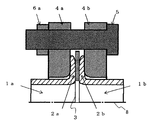
図1に、本発明の一実施形態にかかるルーズフランジ式フレア管継手の一部を模式的に例示する。本実施形態にかかるルーズフランジ式フレア管継手は、2つの鋼管1a、1bの接合部において、各鋼管1a、1bの端部を拡開して成形されたつば状のフレア部2a、2bを、ガスケット3を介して衝合させ、当該衝合された両フレア部2a、2bをその両側からルーズフランジ4a、4bで挟持して、ボルト5とナット6により機械的に締結する構造である。
FIG. 1 schematically illustrates a part of a loose flange type flare pipe joint according to an embodiment of the present invention. The loose-flange type flare pipe joint according to the present embodiment includes flange-shaped flare parts 2a and 2b formed by expanding the ends of the steel pipes 1a and 1b at the joints of the two steel pipes 1a and 1b. The two flared portions 2a and 2b are brought into contact with each other via the
より詳細に説明すると、鋼管1a、1bは、それぞれの端部につば出し加工によって形成されたフレア部2a、2bを有する。フレア部2a、2bは、2本の鋼管1a、1bを相互に接合するために、鋼管1a、1bの端部をその外側に折り曲げるように拡開する成形加工(つまり、フレア加工)された部分である。 If it demonstrates in detail, the steel pipes 1a and 1b have the flare parts 2a and 2b formed by the protrusion process at each edge part. The flare portions 2a and 2b are formed (ie, flared) portions that are expanded so as to bend the end portions of the steel pipes 1a and 1b to bond the two steel pipes 1a and 1b to each other. It is.
このフレア部2a、2bには、それぞれ、ルーズフランジ4a、4bが係合している。このルーズフランジ4a、4b(以下「フランジ4a、4b」という。)は、鋼管1a、1bの外径よりも大きな内経を有する円環状フランジである。かかるフランジ4a、4b内に鋼管1a、1bが挿通され、非締結時には、フランジ4a、4bの内周面は鋼管1a、1bの外周面に沿って摺動可能である。 Loose flanges 4a and 4b are engaged with the flare portions 2a and 2b, respectively. The loose flanges 4a and 4b (hereinafter referred to as “flanges 4a and 4b”) are annular flanges having an inner diameter larger than the outer diameter of the steel pipes 1a and 1b. The steel pipes 1a and 1b are inserted into the flanges 4a and 4b, and when not fastened, the inner peripheral surfaces of the flanges 4a and 4b can slide along the outer peripheral surfaces of the steel pipes 1a and 1b.
鋼管1a、1bのフレア部2a、2bの端面9(図2参照。)同士は、必要に応じてガスケット3を介在させて衝合される。ガスケット3は、例えば、フレア部2a、2bの外径と同程度の外径を有する円環状の封止部材であり、衝合された2つのフレア部2a、2bの端面9の間をシールする機能を有する。フレア部2a、2bの衝合部は、その両側から上記フランジ4a、4bで挟持され、フランジ4a、4bは、ボルト5とナット6で締結されている。
The end faces 9 (see FIG. 2) of the flare portions 2a and 2b of the steel pipes 1a and 1b are brought into contact with each other with a
かかるルーズフランジ式フレア管継手を用いて、鋼管1a、1bを接合する手順について説明する。まず、対向配置された鋼管1aのフレア部2aと鋼管1bのフレア部2bとの間に、ガスケット3を介在させ、その状態でフレア部2aの端面9とフレア部2bの端面9とを衝合させる。次いで、当該衝合されたフレア部2a、2bを、その外側からフランジ4a、4bにより挟持する。その後、フランジ4a、4bに挿通したボルト5とナット6により、フランジ4a、4bを機械的に締結・固定することで、フレア部2a、2bを両側から押圧する。これにより、当該継手を用いて2本の鋼管1a、1bを好適に接合できる。なお、フランジ4a、4bを固定する手段としては、上記ボルト5とナット6の例に限定されず、フランジ4a、4bを機械的に締結・固定するものであれば、任意の固定部材を使用できる。
A procedure for joining the steel pipes 1a and 1b using the loose flange type flare pipe joint will be described. First, the
また、水、空気、蒸気などを移送する配管にはSTPG(JIS G 3454)やSGP(JIS G 3452)等の配管材料が使用され、その外径は50A〜350Aであり、100A前後の鋼管が主流となっている。そこで、本発明者らは100AのSGP配管を想定した有限要素法解析(FEA)により、ルーズフランジ式フレア管継手のシール性に影響を与える設計因子を分析することとした。 In addition, piping materials such as STPG (JIS G 3454) and SGP (JIS G 3452) are used for piping for transferring water, air, steam, etc., and the outer diameter is 50A to 350A, and steel pipes around 100A are used. It has become mainstream. Therefore, the present inventors analyzed the design factors that affect the sealing performance of the loose flange type flare pipe joint by finite element method analysis (FEA) assuming 100A SGP piping.
その結果、発明者らが注目したのは、図2に示す、鋼管1の中心軸8に対するフレア部2の端面9の角度θ(以下「フレア部端面角度θ」という。)である。このフレア部端面角度θと、ルーズフランジ式フレア管継手の衝合部に発生する面圧分布との関係を図3に示す。図3は、フレア部端面角度θを変更させたルーズフランジ式フレア管継手をボルト5で締結し、80MPa相当の曲げ荷重が負荷された際に、衝合部のガスケット3に発生する接触面圧と、当該面圧が発生する位置との関係を示したものである。
As a result, the inventors paid attention to the angle θ of the
図3に示したFEAによる解析結果から、フレア部端面角度θが小さくなるに従って、曲げ荷重負荷時にガスケット3に生じる面圧が高くなることがわかる。したがって、曲げ荷重や引張荷重が負荷された場合、フレア部端面角度θを小さくすれば、継手のシール性が向上すると考えられる。
From the analysis result by FEA shown in FIG. 3, it can be seen that the surface pressure generated in the
そこで、フレア部端面角度θを種々変化させたフレア鋼管1を製造し、継手のシール性の評価試験を行った。まず、100A(外径114.3mm、肉厚4.5mm)のSGP鋼管の端部をフレア加工し、フレア部2を形成した。このフレア部2にフランジ4を係合し、ガスケット3を介して両フレア部2を衝合してフランジ4をボルト5で締結し、ルーズフランジ式フレア管継手とした。
Therefore, a
次に、ルーズフランジ式フレア管継手に、1MPaの空気を充填し、引張軸力を加えながら、空気圧の急激な低下が観察されたときの負荷荷重(リーク荷重)を求めた。このリーク荷重を、鋼管1の管体降伏強度によって除し、シール性指数αを算出した。なお、鋼管の管体降伏強度は、フレア鋼管1と同一のロットの鋼管から試験片を採取して、引張試験を行って測定した。
Next, the loose flange type flare pipe joint was filled with 1 MPa of air, and a load load (leakage load) was observed when a sudden drop in air pressure was observed while applying a tensile axial force. This leak load was divided by the tube body yield strength of the
図4は、上記評価試験により得られたフレア部端面角度θとシール性指数αの関係を示す。これよりフレア部端面角度θが減少するに従い、シール性指数αは増加し、シール性が向上することがわかる。特に、フレア部端面角度θが89゜未満になると、シール性指数αは80%以上になり、シール性の耐荷重特性が向上することが実証できた。しかし、フレア部端面角度θが87゜未満になると、継手締結時又は軸力負荷時にガスケット3が破損した。これは局部的に接触面圧が大きくなりすぎ、ガスケット3の耐荷重抵抗を上回ったものと推測できる。
FIG. 4 shows the relationship between the flare end face angle θ and the sealability index α obtained by the evaluation test. From this, it can be seen that as the flare end face angle θ decreases, the sealability index α increases and the sealability is improved. In particular, when the flare end face angle θ is less than 89 °, the sealability index α is 80% or more, and it was proved that the load resistance characteristic of the sealability is improved. However, when the flare end face angle θ was less than 87 °, the
以上、実管試験よって、管体の降伏荷重に対して80%以上の軸力までガスシールでき、尚かつ、ガスケット3を破損させないためには、フレア部端面角度θを87゜以上、89゜以下の値に制御することが重要であることが確認された。さらに、図4の結果によれば、フレア部端面角度θが88゜以下であれば、シール性指数αは90%以上であるので、フレア部端面角度θが87°〜88゜とすることで、シール性能をさらに向上できる。
As described above, in the actual pipe test, gas sealing can be performed up to an axial force of 80% or more with respect to the yield load of the pipe body, and in order not to damage the
なお、本実施形態にかかる鋼管1の端部にフレア部2を形成する加工法については、これを限定するものではないが、例えば、図5に示すように鋼管1及びコーン7(円錐ローラ)を回転させ、相対的に自転と公転を繰り返して接触させる方法を採用することが好ましい。この方法によって、コーン7の軸と鋼管1の軸との角度を漸次大きくすれば、フレア部端面角度θを徐々に大きくすることが可能であり、フレア部端面角度θを精度良く制御することができる。
In addition, about the processing method which forms the
次に、本発明の実施例として、種々の鋼管1において、フレア部端面角度θを変化させたときのシール性指標αを評価した実験について説明する。
Next, as an example of the present invention, an experiment in which the sealability index α when the flare end surface angle θ is changed in
本実験では、まず、種々のSGP鋼管の端部を図5に示した方法でつば出し加工し、フレア部端面角度θ(図2)を測定した。更に、フレア部2にルーズフランジ4を係合させ、ガスケット3を介在させてフレア部2の端面9同士を衝合し、ボルト5で締結して、ルーズフランジ式フレア管継手を製造した。表1に示したように、試験に供したSGP鋼管は、サイズ65A〜200Aの、鍛接鋼管、電縫鋼管である。なお、これらの鋼管からは、別途、引張試験片を採取して、降伏強度を測定した。
In this experiment, first, end portions of various SGP steel pipes were subjected to a blanking process by the method shown in FIG. 5, and a flare end surface angle θ (FIG. 2) was measured. Furthermore, the
なお、本実験では、ガスケット3として、ニチアス株式会社製“汎用NAジョイントシール TOMBO No.1995”を使用した。このガスケット3は、無機繊維とアラミド繊維に無機充填剤を加え、バインダーとして耐油性合成ゴムを配合した非石綿ジョイントシールである。このガスケット3の寸法は以下の通りである。また、該当規格は、JIS F0602HJ、ASTM104F712100−B5E12M5である。なお、かかるガスケット3は本実験で使用した例であり、本発明のガスケット3がかかる例に限定されるものではない。
サイズ 65Aの鋼管:ガスケット3の外径124mm、内径77mm、厚み3mm
サイズ100Aの鋼管:ガスケット3の外径159mm、内径115mm、厚み3mm
サイズ200Aの鋼管:ガスケット3の外径270mm、内径218mm、厚み3mm
In this experiment, “general-purpose NA joint seal TOMBO No. 1995” manufactured by NICHIAS Corporation was used as the
Size 65A steel pipe:
Steel pipe of size 100A:
Steel pipe of size 200A:
ルーズフランジ式フレア管継手には、1MPaの空気を封入後、引張軸力を加えながら、圧力が急激に低下したときの荷重(リーク荷重)を求めた。このリーク荷重を管体の降伏荷重で除して、シール性指標αを評価した。かかる実験結果を次の表1に示す。 The loose flange type flare pipe joint was filled with 1 MPa of air, and then a load (leakage load) when the pressure suddenly decreased was obtained while applying a tensile axial force. This leak load was divided by the yield load of the tube to evaluate the sealability index α. The experimental results are shown in Table 1 below.

実施例1〜12ではθが本発明の範囲内(87°〜89°)であり、αは80%以上であった。これに対して比較例1〜4、6〜10、13〜16ではθが大きすぎるため、αは80%に満たなかった。また、フレア部端面角度θが小さすぎる比較例5、11、12、17では、継手締結時または引張荷重負荷時にガスケット3が破損した。
In Examples 1 to 12, θ was within the range of the present invention (87 ° to 89 °), and α was 80% or more. On the other hand, in Comparative Examples 1-4, 6-10, and 13-16, since θ was too large, α was less than 80%. In Comparative Examples 5, 11, 12, and 17, where the flare end face angle θ is too small, the
従って、かかる実験結果によれば、フレア部端面角度θが89°より大きいと、シール性指標αが80%未満となり所望のシール性能が得られず、一方、θが87°未満であると、ガスケット3が破損してしまうため、好適でないといえる。これに対して、フレア部端面角度θが87°以上、89°以下であれば、シール性指標αが80%以上となり、継手に過大な外力が負荷された際でも好適なシール性を発揮でき、かつ、ガスケット3も破損しないことが実証されたといえる。
Therefore, according to such experimental results, when the flare end face angle θ is greater than 89 °, the sealability index α is less than 80%, and a desired sealing performance cannot be obtained, whereas, when θ is less than 87 °, Since
以上、本実施形態にかかるルーズフランジ式フレア管継手について詳細に説明した。本実施形態によれば、鋼管1のフレア部端面角度θを適切な角度(87°〜89°)に調整することで、衝合されたフレア部2間に介在するガスケット3に対する接触面圧を適切に高めることができる。従って、地震時などにおいて、継手に過度な引張荷重、曲げ荷重などが負荷された場合においても、継手のシール性を確保して、配管内の移送流体の漏れを防止できる。
The loose flange type flare pipe joint according to the present embodiment has been described in detail above. According to the present embodiment, by adjusting the flare portion end surface angle θ of the
また、本実施形態にかかるルーズフランジ式フレア管継手では、鋼管1の接合部のシール性を向上させるためには、フレア部2をつば出し加工する際にフレア部端面角度θを調整するだけでよい。従って、上記特許文献6のように、テーパー形状を有するフレア部を形成するために、成形加工途中で工具を変更する必要がない。よって、フレア部2のつば出し加工の工程を簡便にすることができる。
Further, in the loose flange type flare pipe joint according to the present embodiment, in order to improve the sealing performance of the joint portion of the
以上、添付図面を参照しながら本発明の好適な実施形態について詳細に説明したが、本発明はかかる例に限定されない。本発明の属する技術の分野における通常の知識を有する者であれば、特許請求の範囲に記載された技術的思想の範疇内において、各種の変更例または修正例に想到し得ることは明らかであり、これらについても、当然に本発明の技術的範囲に属するものと了解される。 The preferred embodiments of the present invention have been described in detail above with reference to the accompanying drawings, but the present invention is not limited to such examples. It is obvious that a person having ordinary knowledge in the technical field to which the present invention pertains can come up with various changes or modifications within the scope of the technical idea described in the claims. Of course, it is understood that these also belong to the technical scope of the present invention.
1:鋼管
2:フレア部
3:ガスケット
4:ルーズフランジ
5:ボルト
6:ナット
7:コーン
8:鋼管の中心軸
9:フレア部の端面
1: Steel pipe 2: Flare part 3: Gasket 4: Loose flange 5: Bolt 6: Nut 7: Cone 8: Center axis of steel pipe 9: End face of flare part
Claims (10)
前記ルーズフランジ式フレア管継手の非締結時の、前記鋼管の中心軸に対する前記フレア部の端面の角度θが87°〜89°であり、
前記ガスケットは非石綿ジョイントシールからなることを特徴とする、ルーズフランジ式フレア管継手。 Loose flange type flare pipe joint in which the flare portions formed by ribbing processing at the ends of two steel pipes are brought into contact with each other with a gasket interposed therebetween, and both flare portions are sandwiched between loose flanges,
When the loose flange type flare pipe joint is not fastened, the angle θ of the end face of the flare portion with respect to the central axis of the steel pipe is 87 ° to 89 °,
The loose flange type flare pipe joint, wherein the gasket is made of a non-asbestos joint seal.
自転する円錐ローラを前記鋼管に対して相対的に公転させながら前記鋼管の端部に接触させ、前記円錐ローラの中心軸と前記鋼管の中心軸との角度を漸次大きくすることにより、前記鋼管の中心軸に対する前記フレア部の端面の角度θが制御されたことを特徴とする、請求項1又は2に記載のルーズフランジ式フレア管継手。 When the loose flange type flare pipe joint is not fastened, the angle θ of the end face of the flare portion with respect to the central axis of the steel pipe is 87 ° to 89 °,
A rotating conical roller is brought into contact with the end of the steel pipe while revolving relatively with respect to the steel pipe, and an angle between the central axis of the conical roller and the central axis of the steel pipe is gradually increased. The loose flange type flare pipe fitting according to claim 1 or 2, wherein an angle θ of an end face of the flare portion with respect to a central axis is controlled.
前記鋼管の中心軸に対する前記フレア部の端面の角度θが87°〜89°であることを特徴とする、ルーズフランジ式フレア管継手用鋼管。 It is a steel pipe which is used for the loose flange type flare pipe joint according to any one of claims 1 to 3, and has a flare part formed by swallowing at an end part,
An angle θ of an end face of the flare portion with respect to a central axis of the steel pipe is 87 ° to 89 °, and the steel tube for loose flange type flare pipe joint.
鋼管の端部につば出し加工によってフレア部を形成するに際し、自転する円錐ローラを前記鋼管に対して相対的に公転させながら前記鋼管の端部に接触させ、前記円錐ローラの中心軸と前記鋼管の中心軸との角度を漸次大きくすることにより、前記鋼管の中心軸に対する前記フレア部の端面の角度θを87°〜89°に制御することを特徴とする、ルーズフランジ式フレア管継手用鋼管の製造方法。 It is a manufacturing method of the steel pipe for loose flange type flare pipe joints as described in any one of Claims 4-6,
When the flare portion is formed at the end portion of the steel pipe by swirling, the conical roller that rotates is brought into contact with the end portion of the steel pipe while revolving relatively with respect to the steel pipe, and the central axis of the conical roller and the steel pipe The angle θ of the end face of the flare portion with respect to the central axis of the steel pipe is controlled to be 87 ° to 89 ° by gradually increasing the angle with the central axis of the steel pipe for a loose flange type flare pipe joint Manufacturing method.
鋼管の端部をつば出し加工することで、前記鋼管の中心軸に対するフレア部の端面の角度θが87°〜89°である前記フレア部を形成する工程と、
2本の前記鋼管の端部にそれぞれ形成された前記フレア部を、非石綿ジョイントシールからなるガスケットを介在させて
衝合する工程と、
前記衝合されたフレア部をルーズフランジで挟持して、機械的に締結する工程と、
を含むことを特徴とする、鋼管の接合方法。 A method of joining steel pipes using loose flange type flare pipe joints,
Forming the flare part in which the angle θ of the end face of the flare part with respect to the central axis of the steel pipe is 87 ° to 89 ° by subjecting the end part of the steel pipe to a process;
A step of abutting the flare portions respectively formed at the ends of the two steel pipes with a gasket made of a non-asbestos joint seal interposed therebetween;
Sandwiching the abutted flare portions with a loose flange and mechanically fastening them;
A method for joining steel pipes, comprising:
Priority Applications (1)
| Application Number | Priority Date | Filing Date | Title |
|---|---|---|---|
| JP2010087950A JP5384416B2 (en) | 2010-04-06 | 2010-04-06 | Loose flange type flare pipe joint, steel pipe for loose flange type flare pipe joint, method for manufacturing steel pipe for loose flange type flare pipe joint, and method for joining steel pipes |
Applications Claiming Priority (1)
| Application Number | Priority Date | Filing Date | Title |
|---|---|---|---|
| JP2010087950A JP5384416B2 (en) | 2010-04-06 | 2010-04-06 | Loose flange type flare pipe joint, steel pipe for loose flange type flare pipe joint, method for manufacturing steel pipe for loose flange type flare pipe joint, and method for joining steel pipes |
Related Parent Applications (1)
| Application Number | Title | Priority Date | Filing Date |
|---|---|---|---|
| JP2008075953A Division JP4551462B2 (en) | 2008-03-24 | 2008-03-24 | Loose Flange Flare Pipe Joint Sealing Improvement Method, Flare End Face Angle Control Method, Loose Flange Flare Pipe Joint, Loose Flange Flare Pipe Steel Pipe, Loose Flange Flare Pipe Steel Manufacturing Method, and Steel Pipe Joining Method |
Publications (2)
| Publication Number | Publication Date |
|---|---|
| JP2010151324A true JP2010151324A (en) | 2010-07-08 |
| JP5384416B2 JP5384416B2 (en) | 2014-01-08 |
Family
ID=42570628
Family Applications (1)
| Application Number | Title | Priority Date | Filing Date |
|---|---|---|---|
| JP2010087950A Expired - Fee Related JP5384416B2 (en) | 2010-04-06 | 2010-04-06 | Loose flange type flare pipe joint, steel pipe for loose flange type flare pipe joint, method for manufacturing steel pipe for loose flange type flare pipe joint, and method for joining steel pipes |
Country Status (1)
| Country | Link |
|---|---|
| JP (1) | JP5384416B2 (en) |
Cited By (1)
| Publication number | Priority date | Publication date | Assignee | Title |
|---|---|---|---|---|
| CN112325014A (en) * | 2020-11-02 | 2021-02-05 | 杭州中瑞瑞泰克复合材料有限公司 | Air pipe assembling method and air pipe assembling structure based on cold-bending formed flange |
Citations (3)
| Publication number | Priority date | Publication date | Assignee | Title |
|---|---|---|---|---|
| JPH05329557A (en) * | 1992-06-02 | 1993-12-14 | Osaka Kokan Kk | Flare working tube made of austenitic stainless steel |
| JPH08210569A (en) * | 1995-01-31 | 1996-08-20 | Nichias Corp | Electrical insulation gasket |
| JPH0953772A (en) * | 1995-08-12 | 1997-02-25 | Shizusei Kogyo Kk | Connecting structure of stainless steel pipe and molding device of connecting end part |
-
2010
- 2010-04-06 JP JP2010087950A patent/JP5384416B2/en not_active Expired - Fee Related
Patent Citations (3)
| Publication number | Priority date | Publication date | Assignee | Title |
|---|---|---|---|---|
| JPH05329557A (en) * | 1992-06-02 | 1993-12-14 | Osaka Kokan Kk | Flare working tube made of austenitic stainless steel |
| JPH08210569A (en) * | 1995-01-31 | 1996-08-20 | Nichias Corp | Electrical insulation gasket |
| JPH0953772A (en) * | 1995-08-12 | 1997-02-25 | Shizusei Kogyo Kk | Connecting structure of stainless steel pipe and molding device of connecting end part |
Cited By (1)
| Publication number | Priority date | Publication date | Assignee | Title |
|---|---|---|---|---|
| CN112325014A (en) * | 2020-11-02 | 2021-02-05 | 杭州中瑞瑞泰克复合材料有限公司 | Air pipe assembling method and air pipe assembling structure based on cold-bending formed flange |
Also Published As
| Publication number | Publication date |
|---|---|
| JP5384416B2 (en) | 2014-01-08 |
Similar Documents
| Publication | Publication Date | Title |
|---|---|---|
| CN102822586B (en) | Mechanically attached fitting for use in a sour environment | |
| KR101947461B1 (en) | Spin forming method | |
| EP2959986B1 (en) | Method and apparatus for manufacturing a pipe element having shoulder, groove and bead | |
| JP4551462B2 (en) | Loose Flange Flare Pipe Joint Sealing Improvement Method, Flare End Face Angle Control Method, Loose Flange Flare Pipe Joint, Loose Flange Flare Pipe Steel Pipe, Loose Flange Flare Pipe Steel Manufacturing Method, and Steel Pipe Joining Method | |
| CA2636750C (en) | Sealing device with ridges for corrugated stainless steel tubing | |
| CN107002914B (en) | Fluid conduit element and method for forming a fluid conduit element | |
| CN107588253A (en) | Steel mesh skeleton pipe joint structure, joint structure manufacturing method and pipe connection structure | |
| US20250129879A1 (en) | Seismic pipe joint | |
| JP5384416B2 (en) | Loose flange type flare pipe joint, steel pipe for loose flange type flare pipe joint, method for manufacturing steel pipe for loose flange type flare pipe joint, and method for joining steel pipes | |
| CN108156818A (en) | Connector | |
| JP2016217518A (en) | Bifurcation structure of fluid pipe and method for attaching coated tubular body of fluid pipe | |
| AU2011286156B2 (en) | High pressure pipe joint | |
| JP5384417B2 (en) | Loose flange type flare pipe joint, steel pipe for loose flange type flare pipe joint, method for manufacturing steel pipe for loose flange type flare pipe joint, and method for joining steel pipes | |
| JP4551463B2 (en) | Loose flange type flare pipe joint sealability improvement method, flare end face angle control method, loose flange type flare pipe fitting, loose flange type flare pipe fitting steel pipe, loose flange type flare pipe fitting manufacturing method, and steel pipe joining Method | |
| CN112262278B (en) | Kit for connection to at least one tube | |
| CN116817065B (en) | A multi-directional displacement and deviation compensation device under high pressure | |
| CN207246606U (en) | Tensile force type pipe fitting | |
| RU2461762C1 (en) | Connection device | |
| RU2757742C2 (en) | Fitting assembly method | |
| CN212131638U (en) | A pipeline in-line connecting device with protective shell and connecting pipeline thereof | |
| RU158170U1 (en) | PIPELINE REPAIR COUPLING | |
| CN202274216U (en) | Double-socket flexible casing | |
| JP3198179U (en) | High pressure joint structure | |
| RU2387911C1 (en) | Procedure for connecting steel and polyethylene pipes | |
| RU57419U1 (en) | COMPACT FLANGE |
Legal Events
| Date | Code | Title | Description |
|---|---|---|---|
| A621 | Written request for application examination |
Free format text: JAPANESE INTERMEDIATE CODE: A621 Effective date: 20100413 |
|
| A977 | Report on retrieval |
Free format text: JAPANESE INTERMEDIATE CODE: A971007 Effective date: 20120119 |
|
| A131 | Notification of reasons for refusal |
Free format text: JAPANESE INTERMEDIATE CODE: A131 Effective date: 20120124 |
|
| A521 | Request for written amendment filed |
Free format text: JAPANESE INTERMEDIATE CODE: A523 Effective date: 20120321 |
|
| A02 | Decision of refusal |
Free format text: JAPANESE INTERMEDIATE CODE: A02 Effective date: 20120731 |
|
| A521 | Request for written amendment filed |
Free format text: JAPANESE INTERMEDIATE CODE: A523 Effective date: 20121024 |
|
| A911 | Transfer to examiner for re-examination before appeal (zenchi) |
Free format text: JAPANESE INTERMEDIATE CODE: A911 Effective date: 20121102 |
|
| A912 | Re-examination (zenchi) completed and case transferred to appeal board |
Free format text: JAPANESE INTERMEDIATE CODE: A912 Effective date: 20130111 |
|
| A61 | First payment of annual fees (during grant procedure) |
Free format text: JAPANESE INTERMEDIATE CODE: A61 Effective date: 20131002 |
|
| R150 | Certificate of patent or registration of utility model |
Free format text: JAPANESE INTERMEDIATE CODE: R150 Ref document number: 5384416 Country of ref document: JP Free format text: JAPANESE INTERMEDIATE CODE: R150 |
|
| S533 | Written request for registration of change of name |
Free format text: JAPANESE INTERMEDIATE CODE: R313533 |
|
| R350 | Written notification of registration of transfer |
Free format text: JAPANESE INTERMEDIATE CODE: R350 |
|
| LAPS | Cancellation because of no payment of annual fees |