JP2010132079A - Reinforcing structure of door for vehicle - Google Patents
Reinforcing structure of door for vehicle Download PDFInfo
- Publication number
- JP2010132079A JP2010132079A JP2008308735A JP2008308735A JP2010132079A JP 2010132079 A JP2010132079 A JP 2010132079A JP 2008308735 A JP2008308735 A JP 2008308735A JP 2008308735 A JP2008308735 A JP 2008308735A JP 2010132079 A JP2010132079 A JP 2010132079A
- Authority
- JP
- Japan
- Prior art keywords
- section
- vehicle
- cross
- inflator
- reinforcing portion
- Prior art date
- Legal status (The legal status is an assumption and is not a legal conclusion. Google has not performed a legal analysis and makes no representation as to the accuracy of the status listed.)
- Granted
Links
Images




Landscapes
- Body Structure For Vehicles (AREA)
Abstract
【課題】ベルトライン補強部に金属エアバッグが設定された車両用ドアにおいて、該金属エアバッグの作動時におけるベルトライン補強部の断面強度や耐力を高めることを目的とする。
【解決手段】車両用ドアのベルトライン補強部18の端部に設けられたインフレータ22が、車両の前面衝突時に作動し、該ベルトライン補強部18の閉断面30内にガスが供給される。これにより、ベルトライン補強部18を構成するアウタパネル26及びインナパネル28の少なくとも一方が展開し、ベルトライン補強部18の断面展開部32が塑性的に展開する。ベルトライン補強部18のうちインフレータ22に合わせて断面が絞られた端部34と、該端部34に設けられたインフレータ22との間には、パイプ部材24が挟み込まれて配置され、かつ該パイプ部材24は断面展開部32まで延びており、これにより該端部34が補強されている。
【選択図】図3An object of the present invention is to provide a vehicle door in which a metal airbag is set in a beltline reinforcing portion, and to increase the cross-sectional strength and proof strength of the beltline reinforcing portion when the metal airbag is operated.
An inflator 22 provided at an end of a beltline reinforcing portion 18 of a vehicle door operates at the time of a frontal collision of the vehicle, and gas is supplied into a closed cross section 30 of the beltline reinforcing portion 18. Thereby, at least one of the outer panel 26 and the inner panel 28 constituting the belt line reinforcing portion 18 is developed, and the cross-section developing portion 32 of the belt line reinforcing portion 18 is plastically developed. A pipe member 24 is sandwiched and disposed between an end portion 34 of which the cross section is narrowed in accordance with the inflator 22 in the belt line reinforcing portion 18 and the inflator 22 provided on the end portion 34, and The pipe member 24 extends to the cross-section development portion 32, whereby the end portion 34 is reinforced.
[Selection] Figure 3
Description
本発明は、車両用ドアの補強構造に関する。 The present invention relates to a reinforcing structure for a vehicle door.
第1の金属層と第2の金属層とから作られ、これらの層の少なくとも1つが可塑的に変形可能となっており、これらの層の周縁を互いにシールして1つのチャンバを構成し、ガス発生手段(インフレータ)から該チャンバにガスを供給するようにした金属エアバッグが開示されている(特許文献1参照)。この従来例には、金属エアバッグを、側面衝突時の保護のためにサイドドア(車両用ドア)に取り付ける点についても開示されている。
しかしながら、金属エアバッグを車両用ドアに取り付ける場合の詳細については、何ら開示されていない。上記した従来例のような金属エアバッグを車両用ドアに適用すべく、例えばベルトライン補強部の端部に比較的外径の小さいインフレータを取り付けた場合、車両の衝突時に該インフレータから供給されるガスが、該ベルトライン補強部の端部から漏れないようにするため、該端部を絞っておく必要があると考えられる。 However, nothing is disclosed about details of attaching a metal airbag to a vehicle door. In order to apply the metal airbag as in the conventional example to the vehicle door, for example, when an inflator having a relatively small outer diameter is attached to the end of the beltline reinforcing portion, the inflator is supplied from the inflator when the vehicle collides. It is considered that it is necessary to squeeze the end portion so that gas does not leak from the end portion of the belt line reinforcing portion.
しかしながら、ベルトライン補強部の端部を絞っただけでは、ベルトライン補強部のうち断面が展開して強度が増す断面展開部との断面強度の差が大きくなるため、何らかの対策が必要とされる。 However, just narrowing the end of the beltline reinforcing part increases the difference in cross-sectional strength between the beltline reinforcing part and the cross-sectional developed part where the cross-section expands and the strength increases. .
本発明は、上記事実を考慮して、ベルトライン補強部に金属エアバッグが設定された車両用ドアにおいて、該金属エアバッグの作動時におけるベルトライン補強部の断面強度や耐力を高めることを目的とする。 In consideration of the above-mentioned facts, the present invention aims to increase the cross-sectional strength and proof strength of a beltline reinforcing portion during operation of the metal airbag in a vehicle door in which a metal airbag is set in the beltline reinforcing portion. And
請求項1の発明は、車両用ドアの上縁において車両前後方向に延び、車両外側に位置するアウタパネルと車両内側に位置するインナパネルにより構成される閉断面を有すると共に、前記アウタパネル及び前記インナパネルの少なくとも一方が、前記閉断面内に供給されるガスの圧力により展開することで塑性的に展開する断面展開部を有するベルトライン補強部と、該ベルトライン補強部の端部に設けられ、車両の前面衝突時に前記閉断面内にガスを供給するインフレータと、前記ベルトライン補強部のうち前記インフレータに合わせて断面が絞られた前記端部を補強するように、該端部と前記インフレータとの間に挟み込まれて配置され、前記断面展開部まで延びるパイプ部材と、を有している。 The invention according to claim 1 has a closed cross section that extends in the vehicle front-rear direction at the upper edge of the vehicle door and includes an outer panel positioned on the vehicle outer side and an inner panel positioned on the vehicle inner side, and the outer panel and the inner panel. At least one of the beltline reinforcing part having a cross-sectionally developed part that develops plastically by being developed by the pressure of the gas supplied in the closed cross-section, and an end of the beltline reinforcing part. An inflator for supplying gas into the closed cross section at the time of a frontal collision, and the end portion and the inflator so as to reinforce the end portion of the beltline reinforcing portion whose cross section is narrowed to match the inflator A pipe member that is sandwiched between the pipe members and extends to the cross-section development portion.
請求項1に記載の車両用ドアの補強構造では、車両用ドアのベルトライン補強部の端部に設けられたインフレータが、車両の前面衝突時に作動し、該ベルトライン補強部の閉断面内にガスが供給される。これにより、ベルトライン補強部を構成するアウタパネル及びインナパネルの少なくとも一方が展開し、ベルトライン補強部の断面展開部が塑性的に展開する。これにより、車両用ドアに入力される軸圧縮荷重に対するベルトライン補強部の断面強度や耐力を向上させることができる。 In the vehicle door reinforcing structure according to claim 1, the inflator provided at the end of the belt line reinforcing portion of the vehicle door operates in the event of a frontal collision of the vehicle, and is within the closed cross section of the belt line reinforcing portion. Gas is supplied. As a result, at least one of the outer panel and the inner panel constituting the beltline reinforcing portion is developed, and the cross-section developing portion of the beltline reinforcing portion is plastically developed. Thereby, the cross-sectional strength and proof stress of the beltline reinforcement part with respect to the axial compression load input into the vehicle door can be improved.
ここで、ベルトライン補強部のうちインフレータに合わせて断面が絞られた端部と、該端部に設けられたインフレータとの間には、パイプ部材が挟み込まれて配置され、かつ該パイプ部材は断面展開部まで延びており、これによって該ベルトライン補強部の端部が補強されているので、該端部の断面がインフレータに合わせて絞られていても、該端部の断面強度や耐力を確保することができる。従って、ベルトライン補強部に金属エアバッグが設定された車両用ドアにおいて、該金属エアバッグの作動時におけるベルトライン補強部の断面強度や耐力を高めることができる。 Here, a pipe member is sandwiched between the end portion of the beltline reinforcing portion whose section is narrowed to match the inflator and the inflator provided at the end portion, and the pipe member is Since the end of the beltline reinforcing part is reinforced by this, the cross-sectional strength and proof strength of the end are reduced even when the cross-section of the end is squeezed to match the inflator. Can be secured. Therefore, in the vehicle door in which the metal airbag is set in the beltline reinforcing portion, the cross-sectional strength and proof strength of the beltline reinforcing portion when the metal airbag is activated can be increased.
請求項2の発明は、車両用ドアの上縁において車両前後方向に延び、車両外側に位置するアウタパネルと車両内側に位置するインナパネルにより構成される閉断面を有すると共に、前記アウタパネル及び前記インナパネルの少なくとも一方が前記閉断面内に供給されるガスの圧力により塑性的に展開することで該閉断面が展開する断面展開部を有するベルトライン補強部と、カバーに覆われた状態で前記ベルトライン補強部の端部に設けられ、車両の前面衝突時に前記閉断面内にガスを供給するインフレータと、前記ベルトライン補強部のうち前記インフレータに合わせて断面が絞られた前記端部を補強するように、前記アウタパネル及び前記インナパネルと、前記インフレータの前記カバーとを結合する結合部材と、を有している。 The invention according to claim 2 has a closed cross section that extends in the vehicle front-rear direction at the upper edge of the vehicle door and includes an outer panel positioned on the vehicle outer side and an inner panel positioned on the vehicle inner side, and the outer panel and the inner panel. A belt line reinforcing portion having a cross-section development portion in which the closed cross-section is developed by plastic development by the pressure of a gas supplied into the closed cross-section, and the belt line in a state covered with a cover. An inflator that is provided at an end of the reinforcing part and supplies gas into the closed cross section at the time of a frontal collision of the vehicle, and the end of the beltline reinforcing part that has a narrowed cross section to match the inflator And a coupling member that couples the outer panel and the inner panel and the cover of the inflator.
請求項2に記載の車両用ドアの補強構造では、車両用ドアのベルトライン補強部の端部に設けられたインフレータが、車両の前面衝突時に作動し、該ベルトライン補強部の閉断面内にガスが供給される。これにより、ベルトライン補強部を構成するアウタパネル及びインナパネルの少なくとも一方が展開し、ベルトライン補強部の断面展開部が塑性的に展開する。これにより、車両用ドアに入力される軸圧縮荷重に対するベルトライン補強部の断面強度や耐力を高めることができる。 In the vehicle door reinforcing structure according to claim 2, the inflator provided at the end of the belt line reinforcing portion of the vehicle door operates in the event of a frontal collision of the vehicle, and is within the closed cross section of the belt line reinforcing portion. Gas is supplied. As a result, at least one of the outer panel and the inner panel constituting the beltline reinforcing portion is developed, and the cross-section developing portion of the beltline reinforcing portion is plastically developed. Thereby, the cross-sectional strength and proof stress of the beltline reinforcement part with respect to the axial compression load input into the vehicle door can be improved.
ここで、インフレータのカバーと、ベルトライン補強部を構成するアウタパネル及びインナパネルとが、結合部材により結合されており、これによって該ベルトライン補強部の端部が補強されているので、該端部の断面がインフレータに合わせて絞られていても、該端部の断面強度や耐力を確保することができる。従って、ベルトライン補強部に金属エアバッグが設定された車両用ドアにおいて、該金属エアバッグの作動時におけるベルトライン補強部の断面強度や耐力を高めることができる。 Here, the cover of the inflator, the outer panel and the inner panel constituting the belt line reinforcing portion are coupled by a coupling member, and thereby the end portion of the belt line reinforcing portion is reinforced. Even if the cross section is narrowed to match the inflator, the cross-sectional strength and proof strength of the end can be ensured. Therefore, in the vehicle door in which the metal airbag is set in the beltline reinforcing portion, the cross-sectional strength and proof strength of the beltline reinforcing portion when the metal airbag is activated can be increased.
以上説明したように、本発明に係る請求項1に記載の車両用ドアの補強構造によれば、ベルトライン補強部に金属エアバッグが設定された車両用ドアにおいて、該金属エアバッグの作動時におけるベルトライン補強部の断面強度や耐力を高めることができる、という優れた効果が得られる。 As described above, according to the vehicle door reinforcement structure according to claim 1 of the present invention, in the vehicle door in which the metal airbag is set in the beltline reinforcement portion, the metal airbag is activated. An excellent effect is obtained in that the cross-sectional strength and proof strength of the beltline reinforcing portion can be increased.
請求項2に記載の車両用ドアの補強構造によれば、ベルトライン補強部に金属エアバッグが設定された車両用ドアにおいて、該金属エアバッグの作動時におけるベルトライン補強部の断面強度や耐力を高めることができる、という優れた効果が得られる。 According to the vehicle door reinforcement structure according to claim 2, in the vehicle door in which a metal airbag is set in the beltline reinforcement portion, the cross-sectional strength and proof strength of the beltline reinforcement portion when the metal airbag is activated. It is possible to obtain an excellent effect that it can be increased.
以下、本発明の実施の形態を図面に基づき説明する。 Hereinafter, embodiments of the present invention will be described with reference to the drawings.
[第1実施形態]
図2において、本実施の形態に係る車両用ドアの補強構造10は、車両12の側部に設けられる車両用ドア14の上縁、即ちベルトライン16における補強構造に係り、ベルトライン補強部18と、インフレータ22と、パイプ部材24とを有している。
[First Embodiment]
In FIG. 2, the vehicle
図2において、ベルトライン補強部18は、車両用ドア14の上縁において車両前後方向に延び、例えばドアインナパネル25に固定されている。また図6に示されるように、ベルトライン補強部18は、車両外側に位置するアウタパネル26と車両内側に位置するインナパネル28により構成される閉断面30を有している。更に図3から図6において、ベルトライン補強部18は、アウタパネル26及びインナパネル28の少なくとも一方が、閉断面30内に供給されるガスの圧力により展開することで塑性的に展開する断面展開部32を有している。
In FIG. 2, the
図4,図6(A)に示されるように、ベルトライン補強部18のアウタパネル26は、例えば鋼板をプレス成型して構成され、上下のフランジ部26Fの間に、例えば断面波形の凸部26A,26B,26Cが車両外側に膨出形成されている。凸部26A,26Bの間、及び凸部26B,26Cの間は、夫々車両内側に凹設された凹部26D,26Eとなっている。これら凸部26A,26B,26C及び凹部26D,26Eは、断面展開部32において、アウタパネル26の長手方向に沿って延びている。また図4に示されるように、断面展開部32においては、上下のフランジ部26Fの間隔は略一定であり、該断面展開部32より車両前側の端部34においては断面展開部32よりも狭められている。該車両前側の端部34における凸部26Bの車両内側面は、パイプ部材24の外径に対応した円弧面26Gとなっている。
As shown in FIGS. 4 and 6A, the
図4,図6(A)に示されるように、ベルトライン補強部18のインナパネル28は、例えば鋼板をプレス成型して構成され、上下のフランジ部28Fの間に、凸部28Aが車両内側に膨出形成されている。これにより、インナパネル28は、断面略ハット形に構成されている。上下のフランジ部28Fの間隔は、断面展開部32においては略一定であり、該断面展開部32より車両前側の車両前側の端部34においては断面展開部32よりも狭められている。
As shown in FIGS. 4 and 6A, the
図4に示されるように、凸部28Aの車両外側面における車両前側の端部34から断面展開部32にかけての領域には、パイプ部材24の外径に対応した凹部36が形成されている。凹部36の車両後側には、インフレータ22からのガスを閉断面30内に導く傾斜状の案内面38が形成されている。このように、ベルトライン補強部18における車両前側の端部34は、インフレータ22に合わせて断面が絞られている。また図2において、ベルトライン補強部18の車両後側の端部35は、インフレータ22から供給されるガスが漏れないように封止されている。
As shown in FIG. 4, a
図3,図4において、インフレータ22は、ベルトライン補強部18の例えば車両前側の端部34に設けられ、車両12の前面衝突時にベルトライン補強部18の閉断面30内にガスを供給するガス発生器である。このインフレータ22は、例えば円筒状に構成され、後述するパイプ部材24を介して、ベルトライン補強部18のアウタパネル26とインナパネル28とに内に挟み込まれて固定されている。またインフレータ22は、ワイヤハーネス40を介してECUに接続されており、該ECUからの作動電流により作動して、ベルトライン補強部18の閉断面30に対して膨張用のガスを供給するように構成されている。ECUは、衝突センサ(図示せず)からの信号により車両12の前面衝突を判定した際に、インフレータ22に対して作動電流を流すように構成されている。
3 and 4, the
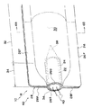
図3,図4において、パイプ部材24は、ベルトライン補強部18のうちインフレータ22の外径に合わせて断面が絞られた車両前側の端部34を補強するように、該端部34とインフレータ22との間に挟み込まれて配置され、断面展開部32まで延びている。具体的には、パイプ部材24は、例えば車両前後方向に貫通した金属円管であり、アウタパネル26の円弧面26Gと、インナパネル28の凹部36との間に挟みこまれている。
3 and 4, the
このように、本実施形態では、断面展開部32を有するベルトライン補強部18の車両前側の端部34に、インフレータ22を設けることで、金属エアバッグ42が構成されている。この金属エアバッグ42は、例えば前後の車両用ドア14に夫々設定されている。
Thus, in this embodiment, the
(作用)
本実施形態は、上記のように構成されており、以下その作用について説明する。図2において、本実施形態に係る車両用ドアの補強構造10では、車両用ドア14のベルトライン16に金属エアバッグ42が設けられているので、車両12(図1)が前面衝突し、図示しない衝突センサからの信号に基づいてECUが該衝突の発生を判定すると、ワイヤハーネス40(図3)を通じて、該ECUからインフレータ22に作動電流が流される。インフレータ22は、該作動電流を受けて作動して、車両後方へ多量のガスを噴出させる。このガスは、ベルトライン補強部18のインナパネル28側においては案内面38により閉断面30内へ導かれ、該ベルトライン補強部18のアウタパネル26側においては直接的に閉断面30内へ供給される。これにより、ベルトライン補強部18の断面展開部32が塑性的に展開する。
(Function)
This embodiment is configured as described above, and the operation thereof will be described below. 2, in the vehicle
具体的には、図6(A),(B)に示されるように、インフレータ22(図3)から閉断面30内へ供給されるガスの圧力により、ベルトライン補強部18を構成するアウタパネル26及びインナパネル28の少なくとも一方が展開する。本実施形態では、アウタパネル26の凹部26D,凹部26Eが車両外側へ反転するように変形して展開すると共に、インナパネル28の凸部28Aが車両内側へ膨らむように変形して、ベルトライン補強部18の断面展開部32が塑性的に展開する(図5も参照)。これにより、車両用ドア14に入力される軸圧縮荷重(図示せず)に対するベルトライン補強部18の断面強度や耐力を高めることができる。
Specifically, as shown in FIGS. 6A and 6B, the
ここで、ベルトライン補強部18のうちインフレータ22に合わせて断面が絞られた車両前側の端部34と、該端部34に設けられたインフレータ22との間には、パイプ部材24が挟み込まれて配置され、かつ該パイプ部材24は断面展開部32まで延びており、これによって該ベルトライン補強部18の車両前側の端部34が補強されているので、該端部34の断面がインフレータ22に合わせて絞られていても、該端部34の断面強度や耐力を確保することができる。これにより、ベルトライン補強部18全体の断面強度や耐力を高めることができる。
Here, the
[第2実施形態]
図7から図9において、本実施の形態に係る車両用ドアの補強構造20では、ベルトライン補強部18のうちインフレータ22に合わせて断面が絞られた車両前側の端部34を補強するように、ベルトライン補強部18のアウタパネル26及びインナパネル28と、インフレータ22のカバー44とが、結合部材46により結合されている。
[Second Embodiment]
7 to 9, in the vehicle
具体的には、インフレータ22は、カバー44に覆われた状態で、ベルトライン補強部18の例えば車両前側の端部34に設けられている。このカバー44は、例えば車両前後方向に貫通した金属円管であり、ベルトライン補強部18におけるアウタパネル26の円弧面26Gと、インナパネル28の凹部36との間に挟みこまれている。
Specifically, the
結合部材46は、例えばカバー44の上側後部及び下側後部から、夫々車両後方の斜め上方及び車両後方の斜め下方に延びる板状のステーである。結合部材46の後端部46Aは、アウタパネル26及びインナパネル28における上下のフランジ部26F,28Fに挟まれて、例えばスポット溶接により固定される。このため、フランジ部26Fの車両内側面と、フランジ部28Fの車両外側面には、該後端部46Aに対応した取付け座26H,28Hが夫々凹設されている。
The
他の部分については、第1実施形態と同様であるので、同一の部分には図面に同一の符号を付し、説明を省略する。 Since other parts are the same as those in the first embodiment, the same parts are denoted by the same reference numerals in the drawings, and the description thereof is omitted.
(作用)
本実施形態は、上記のように構成されており、以下その作用について説明する。車両12(図1)の前面衝突時にインフレータ22からベルトライン補強部18の閉断面30内にガスが供給されて、断面展開部32が塑性的に展開する作用は、第1実施形態と同様である。
(Function)
This embodiment is configured as described above, and the operation thereof will be described below. The action in which gas is supplied from the inflator 22 into the
本実施形態では、ベルトライン補強部18の車両前側の端部34に設けられたインフレータ22と、該ベルトライン補強部18を構成するアウタパネル26及びインナパネル28とが、結合部材46により結合されており、これによって該ベルトライン補強部18の車両前側の端部34が補強されているので、該端部34の断面がインフレータ22に合わせて絞られていても、該端部34の断面強度や耐力を確保することができる。
In this embodiment, the inflator 22 provided at the
具体的には、車両12(図1)の前面衝突時に、車両用ドア14(図1)におけるベルトライン補強部18の車両前側の端部34に入力された軸圧縮荷重は、インフレータ22のカバー44から、上下の結合部材46を介して、アウタパネル26の上下のフランジ部26Fと、インナパネル28の上下のフランジ部28Fとに分散して伝達される。これにより、車両前側の端部34の変形が抑制されるので、ベルトライン補強部18全体の断面強度や耐力を高めることができる。
Specifically, at the time of a frontal collision of the vehicle 12 (FIG. 1), the axial compressive load input to the
なお、上記各実施形態において、インフレータ22がベルトライン補強部18の車両前側の端部34に設けられるものとしたが、これに限られず、車両後側の端部35にインフレータ22を設け、車両前側の端部34を封止するように構成してもよい。
In each of the above embodiments, the
10 車両用ドアの補強構造
12 車両
14 車両用ドア
18 ベルトライン補強部
20 車両用ドアの補強構造
22 インフレータ
24 パイプ部材
26 アウタパネル
28 インナパネル
30 閉断面
32 断面展開部
34 端部
44 カバー
46 結合部材
DESCRIPTION OF
Claims (2)
該ベルトライン補強部の端部に設けられ、車両の前面衝突時に前記閉断面内にガスを供給するインフレータと、
前記ベルトライン補強部のうち前記インフレータに合わせて断面が絞られた前記端部を補強するように、該端部と前記インフレータとの間に挟み込まれて配置され、前記断面展開部まで延びるパイプ部材と、
を有する車両用ドアの補強構造。 The upper edge of the vehicle door extends in the vehicle front-rear direction and has a closed cross section composed of an outer panel positioned outside the vehicle and an inner panel positioned inside the vehicle, and at least one of the outer panel and the inner panel is the closed panel. A beltline reinforcing portion having a cross-section development portion that is plastically developed by being developed by the pressure of a gas supplied in the cross-section;
An inflator that is provided at an end of the beltline reinforcing portion and supplies gas into the closed section at the time of a frontal collision of a vehicle;
A pipe member disposed between the end portion and the inflator so as to reinforce the end portion of the beltline reinforcing portion whose section is narrowed in accordance with the inflator, and extends to the cross-section development portion When,
A vehicle door reinforcing structure.
カバーに覆われた状態で前記ベルトライン補強部の端部に設けられ、車両の前面衝突時に前記閉断面内にガスを供給するインフレータと、
前記ベルトライン補強部のうち前記インフレータに合わせて断面が絞られた前記端部を補強するように、前記アウタパネル及び前記インナパネルと、前記インフレータの前記カバーとを結合する結合部材と、
を有する車両用ドアの補強構造。 The upper edge of the vehicle door extends in the vehicle front-rear direction and has a closed cross section configured by an outer panel positioned on the vehicle outer side and an inner panel positioned on the vehicle inner side, and at least one of the outer panel and the inner panel is the closed cross section. A belt line reinforcing portion having a cross-section expanding portion in which the closed cross-section is expanded by plastically expanding by the pressure of the gas supplied therein;
An inflator provided at an end of the beltline reinforcing portion in a state of being covered by a cover, and supplying gas into the closed cross section at the time of a frontal collision of a vehicle;
A coupling member that couples the outer panel and the inner panel and the cover of the inflator so as to reinforce the end portion of the beltline reinforcing portion whose cross section is narrowed in accordance with the inflator;
A vehicle door reinforcing structure.
Priority Applications (1)
| Application Number | Priority Date | Filing Date | Title |
|---|---|---|---|
| JP2008308735A JP5398243B2 (en) | 2008-12-03 | 2008-12-03 | Vehicle door reinforcement structure |
Applications Claiming Priority (1)
| Application Number | Priority Date | Filing Date | Title |
|---|---|---|---|
| JP2008308735A JP5398243B2 (en) | 2008-12-03 | 2008-12-03 | Vehicle door reinforcement structure |
Publications (2)
| Publication Number | Publication Date |
|---|---|
| JP2010132079A true JP2010132079A (en) | 2010-06-17 |
| JP5398243B2 JP5398243B2 (en) | 2014-01-29 |
Family
ID=42343861
Family Applications (1)
| Application Number | Title | Priority Date | Filing Date |
|---|---|---|---|
| JP2008308735A Expired - Fee Related JP5398243B2 (en) | 2008-12-03 | 2008-12-03 | Vehicle door reinforcement structure |
Country Status (1)
| Country | Link |
|---|---|
| JP (1) | JP5398243B2 (en) |
Cited By (3)
| Publication number | Priority date | Publication date | Assignee | Title |
|---|---|---|---|---|
| US10434970B2 (en) | 2016-12-08 | 2019-10-08 | Toyota Jidosha Kabushiki Kaisha | Vehicle side section structure |
| US10618437B2 (en) | 2018-01-18 | 2020-04-14 | Toyota Jidosha Kabushiki Kaisha | Vehicle seat |
| US10632884B2 (en) | 2018-01-18 | 2020-04-28 | Toyota Jidosha Kabushiki Kaisha | Vehicle seat |
Citations (3)
| Publication number | Priority date | Publication date | Assignee | Title |
|---|---|---|---|---|
| US5845937A (en) * | 1997-02-10 | 1998-12-08 | Morton International, Inc. | Structural assembly |
| WO2000050270A1 (en) * | 1999-02-24 | 2000-08-31 | Automotive Development Specialists Ltd. | Inflatable protection apparatus |
| WO2005012051A1 (en) * | 2003-07-31 | 2005-02-10 | Autoliv Asp, Inc. | Adapter unit for a knee airbag |
-
2008
- 2008-12-03 JP JP2008308735A patent/JP5398243B2/en not_active Expired - Fee Related
Patent Citations (3)
| Publication number | Priority date | Publication date | Assignee | Title |
|---|---|---|---|---|
| US5845937A (en) * | 1997-02-10 | 1998-12-08 | Morton International, Inc. | Structural assembly |
| WO2000050270A1 (en) * | 1999-02-24 | 2000-08-31 | Automotive Development Specialists Ltd. | Inflatable protection apparatus |
| WO2005012051A1 (en) * | 2003-07-31 | 2005-02-10 | Autoliv Asp, Inc. | Adapter unit for a knee airbag |
Cited By (3)
| Publication number | Priority date | Publication date | Assignee | Title |
|---|---|---|---|---|
| US10434970B2 (en) | 2016-12-08 | 2019-10-08 | Toyota Jidosha Kabushiki Kaisha | Vehicle side section structure |
| US10618437B2 (en) | 2018-01-18 | 2020-04-14 | Toyota Jidosha Kabushiki Kaisha | Vehicle seat |
| US10632884B2 (en) | 2018-01-18 | 2020-04-28 | Toyota Jidosha Kabushiki Kaisha | Vehicle seat |
Also Published As
| Publication number | Publication date |
|---|---|
| JP5398243B2 (en) | 2014-01-29 |
Similar Documents
| Publication | Publication Date | Title |
|---|---|---|
| JP5786886B2 (en) | Car cabin front structure | |
| CN103052541B (en) | The B post reinforcement of motor vehicles | |
| CN1958347B (en) | Reinforced body structure for side impact resistance | |
| JP6306543B2 (en) | Vehicle side structure | |
| JP5177397B2 (en) | Bumper structure | |
| JP2007196796A (en) | Hood airbag device for vehicle | |
| JP5398243B2 (en) | Vehicle door reinforcement structure | |
| JP5711942B2 (en) | Cowl top cover | |
| JP2011218979A (en) | Roof side structure of vehicle body | |
| JP5130265B2 (en) | Arrangement structure of airbag device for passenger seat | |
| JP2008296644A (en) | Arrangement structure of head protection airbag device | |
| JP6432560B2 (en) | Side door structure for vehicles | |
| JP2016124382A (en) | Side impact load transmission structure of vehicle | |
| JP5045313B2 (en) | Knee airbag device for vehicle | |
| JP6125482B2 (en) | Automotive bumper | |
| US20060012220A1 (en) | Motor vehicle having an energy-absorbing deformation element | |
| JP3772745B2 (en) | Reinforcement structure of body frame | |
| JP2009516617A (en) | Safety system | |
| JP2008222095A (en) | Side impact sensor mounting structure | |
| JP4089723B2 (en) | Hood airbag device for vehicle | |
| JP5772619B2 (en) | Airbag device for passenger seat | |
| JP5768668B2 (en) | Vehicle side door structure | |
| JP4779640B2 (en) | Hood airbag device for vehicle | |
| JP5229260B2 (en) | Knee airbag device for vehicle | |
| JP2009298177A (en) | Air bag module mounting bracket |
Legal Events
| Date | Code | Title | Description |
|---|---|---|---|
| A711 | Notification of change in applicant |
Free format text: JAPANESE INTERMEDIATE CODE: A711 Effective date: 20110831 |
|
| A521 | Written amendment |
Free format text: JAPANESE INTERMEDIATE CODE: A821 Effective date: 20110901 |
|
| A621 | Written request for application examination |
Free format text: JAPANESE INTERMEDIATE CODE: A621 Effective date: 20110920 |
|
| A977 | Report on retrieval |
Free format text: JAPANESE INTERMEDIATE CODE: A971007 Effective date: 20130328 |
|
| A131 | Notification of reasons for refusal |
Free format text: JAPANESE INTERMEDIATE CODE: A131 Effective date: 20130402 |
|
| A601 | Written request for extension of time |
Free format text: JAPANESE INTERMEDIATE CODE: A601 Effective date: 20130701 |
|
| A602 | Written permission of extension of time |
Free format text: JAPANESE INTERMEDIATE CODE: A602 Effective date: 20130704 |
|
| A601 | Written request for extension of time |
Free format text: JAPANESE INTERMEDIATE CODE: A601 Effective date: 20130723 |
|
| A602 | Written permission of extension of time |
Free format text: JAPANESE INTERMEDIATE CODE: A602 Effective date: 20130726 |
|
| A521 | Written amendment |
Free format text: JAPANESE INTERMEDIATE CODE: A523 Effective date: 20130830 |
|
| TRDD | Decision of grant or rejection written | ||
| A01 | Written decision to grant a patent or to grant a registration (utility model) |
Free format text: JAPANESE INTERMEDIATE CODE: A01 Effective date: 20131008 |
|
| A61 | First payment of annual fees (during grant procedure) |
Free format text: JAPANESE INTERMEDIATE CODE: A61 Effective date: 20131022 |
|
| R150 | Certificate of patent or registration of utility model |
Ref document number: 5398243 Country of ref document: JP Free format text: JAPANESE INTERMEDIATE CODE: R150 Free format text: JAPANESE INTERMEDIATE CODE: R150 |
|
| R250 | Receipt of annual fees |
Free format text: JAPANESE INTERMEDIATE CODE: R250 |
|
| R250 | Receipt of annual fees |
Free format text: JAPANESE INTERMEDIATE CODE: R250 |
|
| R250 | Receipt of annual fees |
Free format text: JAPANESE INTERMEDIATE CODE: R250 |
|
| R250 | Receipt of annual fees |
Free format text: JAPANESE INTERMEDIATE CODE: R250 |
|
| LAPS | Cancellation because of no payment of annual fees |