JP2010103034A - Linear light source device - Google Patents
Linear light source device Download PDFInfo
- Publication number
- JP2010103034A JP2010103034A JP2008275369A JP2008275369A JP2010103034A JP 2010103034 A JP2010103034 A JP 2010103034A JP 2008275369 A JP2008275369 A JP 2008275369A JP 2008275369 A JP2008275369 A JP 2008275369A JP 2010103034 A JP2010103034 A JP 2010103034A
- Authority
- JP
- Japan
- Prior art keywords
- light guide
- light
- light source
- source device
- linear
- Prior art date
- Legal status (The legal status is an assumption and is not a legal conclusion. Google has not performed a legal analysis and makes no representation as to the accuracy of the status listed.)
- Pending
Links
Images


Classifications
-
- G—PHYSICS
- G02—OPTICS
- G02B—OPTICAL ELEMENTS, SYSTEMS OR APPARATUS
- G02B6/00—Light guides; Structural details of arrangements comprising light guides and other optical elements, e.g. couplings
- G02B6/0001—Light guides; Structural details of arrangements comprising light guides and other optical elements, e.g. couplings specially adapted for lighting devices or systems
- G02B6/0005—Light guides; Structural details of arrangements comprising light guides and other optical elements, e.g. couplings specially adapted for lighting devices or systems the light guides being of the fibre type
- G02B6/001—Light guides; Structural details of arrangements comprising light guides and other optical elements, e.g. couplings specially adapted for lighting devices or systems the light guides being of the fibre type the light being emitted along at least a portion of the lateral surface of the fibre
-
- F—MECHANICAL ENGINEERING; LIGHTING; HEATING; WEAPONS; BLASTING
- F21—LIGHTING
- F21V—FUNCTIONAL FEATURES OR DETAILS OF LIGHTING DEVICES OR SYSTEMS THEREOF; STRUCTURAL COMBINATIONS OF LIGHTING DEVICES WITH OTHER ARTICLES, NOT OTHERWISE PROVIDED FOR
- F21V7/00—Reflectors for light sources
- F21V7/04—Optical design
-
- G—PHYSICS
- G02—OPTICS
- G02B—OPTICAL ELEMENTS, SYSTEMS OR APPARATUS
- G02B6/00—Light guides; Structural details of arrangements comprising light guides and other optical elements, e.g. couplings
- G02B6/0001—Light guides; Structural details of arrangements comprising light guides and other optical elements, e.g. couplings specially adapted for lighting devices or systems
- G02B6/0005—Light guides; Structural details of arrangements comprising light guides and other optical elements, e.g. couplings specially adapted for lighting devices or systems the light guides being of the fibre type
- G02B6/0006—Coupling light into the fibre
-
- G—PHYSICS
- G02—OPTICS
- G02B—OPTICAL ELEMENTS, SYSTEMS OR APPARATUS
- G02B6/00—Light guides; Structural details of arrangements comprising light guides and other optical elements, e.g. couplings
- G02B6/0001—Light guides; Structural details of arrangements comprising light guides and other optical elements, e.g. couplings specially adapted for lighting devices or systems
- G02B6/0011—Light guides; Structural details of arrangements comprising light guides and other optical elements, e.g. couplings specially adapted for lighting devices or systems the light guides being planar or of plate-like form
- G02B6/0013—Means for improving the coupling-in of light from the light source into the light guide
- G02B6/0023—Means for improving the coupling-in of light from the light source into the light guide provided by one optical element, or plurality thereof, placed between the light guide and the light source, or around the light source
- G02B6/0028—Light guide, e.g. taper
Landscapes
- Physics & Mathematics (AREA)
- General Physics & Mathematics (AREA)
- Optics & Photonics (AREA)
- Engineering & Computer Science (AREA)
- General Engineering & Computer Science (AREA)
- Planar Illumination Modules (AREA)
- Non-Portable Lighting Devices Or Systems Thereof (AREA)
- Facsimile Scanning Arrangements (AREA)
- Light Guides In General And Applications Therefor (AREA)
- Light Sources And Details Of Projection-Printing Devices (AREA)
Abstract
【課題】
本発明の目的は、他端側の照度の広がりを大きくした線状光源装置を提供することである。
【解決手段】
第1の発明に係る線状光源装置は、長手方向に沿った外面に溝が設けられた導光体と、該導光体の長手方向の一端に対向する光源と、からなる線状光源装置において、該導光体の長手方向の他端に対向する拡散反射体が設けられたことを特徴とする。
【選択図】図1【Task】
The objective of this invention is providing the linear light source device which enlarged the breadth of the illumination intensity on the other end side.
[Solution]
A linear light source device according to a first aspect of the present invention is a linear light source device comprising: a light guide body provided with a groove on the outer surface along the longitudinal direction; and a light source facing one end in the longitudinal direction of the light guide body. In the present invention, a diffuse reflector opposing the other end in the longitudinal direction of the light guide is provided.
[Selection] Figure 1
Description
本発明は、ファクシミリ、複写機、イメージスキャナ、バーコードリーダなどに使用する画像読取装置の照明用光源や液晶パネルの導光板を使用したバックライトのエッジ照明用光源などに用いられる線状光源装置に関する。 The present invention relates to a linear light source device used for an illumination light source of an image reading apparatus used for a facsimile, a copying machine, an image scanner, a barcode reader, etc., or a backlight edge illumination light source using a light guide plate of a liquid crystal panel. About.
従来、パーソナルファクシミリなどの画像読取装置において、線状光源装置として特許文献1に記載されるものが知られていた。特許文献1の図3に記載の線状光源装置は、円柱状の導光体と、該導光体の長手方向の一端に設けた光源とにより構成され、該光源はハロゲンランプが用いられていた。
Conventionally, as an image reading apparatus such as a personal facsimile, a linear light source device described in
近年、パーソナルファクシミリなどの画像読取装置において、発光ダイオード(以下、LED(Light Emitthing Diode)と言う)の出力向上により、小型で低消費電力のLEDが線状光源装置の光源として使用されるようになってきている(特許文献2参照)。 In recent years, in an image reading apparatus such as a personal facsimile, a light emitting diode (hereinafter referred to as a light emitting diode (LED)) is improved so that a small and low power consumption LED is used as a light source of a linear light source device. (See Patent Document 2).
図15は、従来に係る線状光源装置1の説明図であり、円柱状の導光体3の長手方向に沿った断面図である。
従来の線状光源装置1は、円柱状の導光体3と、該導光体3の長手方向における一端面33に対向させた光源2(LED)と、該導光体3の長手方向の他端面34に反射面91を対向させた反射体9と、により構成される。
該導光体3には、その長手方向に沿って伸びる外面に溝31が設けられる。該溝31は、切り込み方向が導光体3の軸方向と直交するように構成される。
FIG. 15 is an explanatory diagram of the conventional linear
A conventional linear
The
光源2は、基板22に載置された発光素子(不図示)と、その外周を封止する半球状の封止体23と、該封止体23を取り囲む反射鏡21と、により構成される(詳細は、特許文献2の図16を参照)。
図示しない発光素子からの出射光Sは、透光性を有する封止体23を透過して導光体3の一端面33に向かって出射され、該導光体3の一端面33から導光体3の内部に取り込まれる。このとき、封止体23を透過した光の一部は、光源2が具備する反射鏡21に向かうが、反射鏡21に反射されて、導光体3の一端面33に向かうので、反射鏡21による反射光も導光体3の一端面33から導光体3の内部に取り込まれる。これら導光体3に取り込まれた光Sは、導光体3の内部で反射を繰り返し、溝31の傾斜した面に反射され、導光体3の溝31に対向する面(出射面32)から出射される。
このように、導光体3の出射面32からは、導光体3の長手方向に沿って線状に出射光Sが出射される。
光源2からの出射光Sの中には、導光体3の出射面32から出射されずに、導光体3の長手方向の他端面34までに至るものがある。この導光体3の他端面34に至った光は、導光体3の他端面34に対向された反射面91によって鏡面反射(すなわち、正反射)され、再度導光体3の内部に取り込まれる。
The
Outgoing light S from a light-emitting element (not shown) passes through the light-transmitting sealing
Thus, the outgoing light S is emitted linearly from the
Among the emitted light S from the
従来に係る線状光源装置1は、画像読取装置の用途において、CCDセンサーなどの電子受光素子(不図示)が用いられ、線状光源装置1からの線状の出射光Sを電子受光素子(不図示)により受光される。
ところが、従来に係る線状光源装置1からの線状の出射光Sは、電子受光素子(不図示)で受光すると、その線状の出射光Sの照度分布が変化することがあった。これは、特許文献3の段落番号0004に記載されるように、電子受光素子(不図示)の読取位置は導光体3の軸方向に対して垂直方向に向かってずれることがあり、この読取位置ズレにより、照度分布が変化したものと考えられる。具体的には、図16及び図17を用いて説明する。
The linear
However, when the linear emitted light S from the conventional linear
図16は、図15の従来に係る線状光源装置1の出射面32側から見た上面図である。図17(a)(b)は、図16の従来に係る線状光源装置1の軸方向に対して直交する面の断面図(図17(a)が図16のC−C断面図、図17(b)が図16のD−D断面図)である。
なお、図16及び図17には、図15に示したものと同じものに同一の符号が付している。
FIG. 16 is a top view of the conventional linear
In FIGS. 16 and 17, the same components as those shown in FIG. 15 are denoted by the same reference numerals.
従来に係る線状光源装置1は、導光体3の一端側33にのみ光源2を設けている。このため、導光体3の出射面32から出射される光Sは、図16に示すように、一端側33から取り込まれた光が、導光体3の内部で導光され、導光体3の一端側33から導光体3の他端側34に伸びる線状に出射される。このとき、導光体3に取り込まれた光Sは、導光体3の一端側33において、導光体3の軸方向に対して角度成分の大きい光S1を有しており、この光が溝31に反射されると、出射面32からは、図17(a)に示すような広がりを持った光S1が出射される。
ところが、取り込まれた光Sの中で、導光体3の軸方向に対して角度成分の大きい光S1は、導光体3の一端側33から中央部の間で殆んど出射面32から出射されたり、導光体3の側面(導光体3の外面における出射面32から溝31との間の面)で屈折されて角度成分が変化してしまう。このため、導光体3の他端側34にたどり着く光Sは、導光体3の軸方向に対して角度成分の小さい光S2ばかりになってしまう。当然、導光体3の他端側34に設けた反射体9に反射される光Sも、角度成分の小さな光S2であり、この反射体9は鏡面反射、すなわち正反射を行なうものであるので、反射体9によって反射された光も角度成分の小さな光S2であった。よって、導光体3の他端側34の出射面32から出射される光Sは、図17(b)に示すように、一端側33よりも広がりが小さくなってしまう。
The conventional linear
However, in the captured light S, the light S1 having a large angular component with respect to the axial direction of the
このように、従来に係る線状光源装置1は、その長手方向の一端側33における断面の照度分布と他端側34における照度分布とが異なっている。このため、電子受光素子(不図示)で導光体3から出射された線状光をその長手方向に沿って読み取るとき、その中心軸に沿って読み取った照度分布と、電子受光素子の読取位置が中央部から横方向(Z軸方向)にずれた位置での照度分布とが、異なってしまう。この点について、図18を用いて説明する。
図18(a)は、紙面下側に図15の線状光源装置1を示しており、紙面上側にこの線状光源装置1の長手方向に沿って電子受光素子X1,X2で読み取った相対照度の測定結果である。図18(b)及び(c)は、図17(a)及び(b)の断面と同一であり、各断面において電子受光素子X1,X2の読取位置を示したものである。
なお、図18には、図15〜17に示したものと同じものに同一の符号が付している。
図18(b)及び図18(c)に示すように、導光体3の中心軸の外方に電子受光素子X1を位置させたとき、導光体3の中心軸方向に沿って電子受光素子X1で照度を読み取ると、図18(a)の紙面上側の図の実線のようになり、その相対強度は一定となることが分かる。
ところが、図18(b)に示すように、導光体3の一端側33の断面においては光の広がりが大きいのに対し、図18(c)に示すように、導光体3の他端側34の断面においては光の広がりが小さい。このため、導光体3の中心軸の外方から横方向(図18においてZ軸方向)に移動させた電子受光素子X2では、導光体3の中心軸方向に沿って照度を読み取ると、図18(a)の紙面上側の図の点線のようになり、その相対強度が導光体3の一端側33から他端側34に向かうにつれて落ち込んでしまうことが分かる。
上記のように、従来に係る線状光源装置1は、電子受光素子による読み取る位置によって、導光体3の長手方向における照度分布が変化してしまう問題があった。
Thus, the linear
FIG. 18A shows the linear
In FIG. 18, the same components as those shown in FIGS.
As shown in FIG. 18B and FIG. 18C, when the electron light receiving element X1 is positioned outside the central axis of the
However, as shown in FIG. 18 (b), the light spread is large in the cross section of the one
As described above, the linear
そこで、本発明の目的は、他端側の照度の広がりを大きくした線状光源装置を提供することである。 Therefore, an object of the present invention is to provide a linear light source device in which the spread of illuminance on the other end side is increased.
第1の発明に係る線状光源装置は、長手方向に沿った外面に溝が設けられた導光体と、該導光体の長手方向の一端に対向する光源と、からなる線状光源装置において、該導光体の長手方向の他端に対向する拡散反射体が設けられたことを特徴とする。 A linear light source device according to a first aspect of the present invention is a linear light source device comprising: a light guide body provided with a groove on the outer surface along the longitudinal direction; and a light source facing one end in the longitudinal direction of the light guide body. In the present invention, a diffuse reflector opposing the other end in the longitudinal direction of the light guide is provided.
第2の発明に係る線状光源装置は、第1の発明において、該導光体と該拡散反射体とが離隔されたことを特徴とする。 A linear light source device according to a second invention is characterized in that, in the first invention, the light guide and the diffuse reflector are separated from each other.
第3の発明に係る線状光源装置は、長手方向に沿った外面に溝が設けられた導光体と、該導光体の長手方向の一端に対向する光源と、からなる線状光源装置において、該導光体の長手方向の他端面に凹凸を設けたことを特徴とする。 A linear light source device according to a third aspect of the present invention is a linear light source device comprising: a light guide body provided with a groove on the outer surface along the longitudinal direction; and a light source facing one end in the longitudinal direction of the light guide body. And the other end face in the longitudinal direction of the light guide is provided with unevenness.
第4の発明に係る線状光源装置は、第3の発明において、該導光体の他端面に対向する鏡面反射体が設けられたことを特徴とする。 According to a fourth aspect of the present invention, there is provided a linear light source device according to the third aspect, further comprising a specular reflector that faces the other end surface of the light guide.
第1の発明及び第3の発明に係る線状光源装置は、一端側から取り込まれた光が、他端に設けた拡散反射体によって拡散され、その拡散光の中に導光体の軸方向に対して角度成分の大きい光が含まれていることから、他端側の照度の広がりを大きくすることができる。 In the linear light source device according to the first and third inventions, the light taken in from one end side is diffused by the diffuse reflector provided at the other end, and the axial direction of the light guide in the diffused light Since the light having a large angle component is included, the illuminance spread on the other end side can be increased.
第2の発明及び第4の発明に係る線状光源装置は、導光体と拡散反射体とが離隔されることで、拡散反射体によって拡散された光が、導光体の他端面から取り込まれるときに、導光体の軸方向に対して角度成分が小さくなる。これにより、角度成分を小さくした拡散光が、導光体の中央部にまで届けることができ、導光体の中央部における照度分布の広がりが小さくなることを抑制できる。 In the linear light source device according to the second and fourth inventions, the light diffused by the diffuse reflector is taken in from the other end surface of the light guide by separating the light guide from the diffuse reflector. The angle component becomes smaller with respect to the axial direction of the light guide. Thereby, the diffused light with a reduced angle component can reach the center of the light guide, and the spread of the illuminance distribution at the center of the light guide can be suppressed.
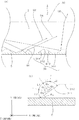
図1〜5は、第1の実施例に係る線状光源装置1の説明図である。
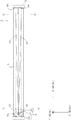
図1は、線状光源装置1の斜視図である。図2は、図1の線状光源装置1の導光体3の軸方向に沿った断面図である。図3は、図2の線状光源装置1の出射面32から見た上面図である。図4(a)は図2の線状光源装置1の他端側の拡大図であり、図4(b)は図4(a)の点線の丸で囲った部分の拡大図である。図5は、図3の線状光源装置1の導光体3の軸方向に対して直交する断面図(図5(a)は図3のA−A断面図、図5(b)は図3のB−B断面図)である。
なお、図1〜5には、図15〜17に示したものと同じものに同一の符号が付されている。
1-5 is explanatory drawing of the linear
FIG. 1 is a perspective view of the linear
1 to 5, the same components as those illustrated in FIGS. 15 to 17 are denoted by the same reference numerals.
第1の実施例に係る線状光源装置1は、長手方向に沿った外面に溝31が設けられた導光体3と、該導光体3の長手方向の一端33に対向する光源2と、該導光体3の長手方向の他端34に対向する拡散反射体4と、により構成される。
The linear
導光体3の外面に設けられる溝形状は種々あるが、第1の実施例においては、例えば導光体3の軸方向に直交する方向(図1におけるZ方向)に切り込んで形成される。このような溝31は、導光体3の長手方向に沿って複数設けられる。
導光体3において、溝31が対向する外面(出射面32)は、好適に光が出射されるように円弧状に形成され(図5参照)、該円弧状の出射面32が導光体3の長手方向に沿った外面に設けられる。これにより、導光体3全体は、図1に示すように円柱状に構成される。
導光体3を構成する部材としては、例えばアクリル樹脂,ポリエステル樹脂又はポリカーボネート樹脂のような透光性部材が用いられる。
There are various groove shapes provided on the outer surface of the
In the
As a member constituting the
導光体3の長手方向の一端33には、図2及び図3に示すように、光源2としてLED2が設けられる。
第1の実施例に用いられるLED2は、図示しない発光素子が基板22上に載置され、この発光素子を封止するように半球状の封止体23が設けられ、その封止体23を取り囲むように円錐状の反射面を有する反射鏡21が設けられることで、構成される。
LED2の半球状の封止体23は、図2及び図3に示すように、導光体3の長手方向における平坦な一端面33に対向配置される。
本発明の用途のように、画像読取装置の照明光源2としては、可視光領域の光が用いられることから、第1の実施例に係る光源2には、例えば白色光を出射するLED2が用いられる。
As shown in FIGS. 2 and 3, an
In the
As shown in FIGS. 2 and 3, the
As in the application of the present invention, as the
導光体3の長手方向の平坦な他端面34には、図2及び図3に示すように、拡散反射体4が密着されて設けられる。
この拡散反射体4は、図4に示すように、例えばアクリル樹脂,ポリエステル樹脂又はポリカーボネート樹脂のような透光性部材の内部に、例えば硫酸バリウム、二酸化チタン、硫酸マグネシウム、炭酸マグネシウム、炭酸カルシウム、タルクやマイカのような粒状の白色粒子42を複数封入することで構成される。
図4(b)に示すように、第1の実施例においては、白色粒子は略球状である。このため、導光体3の他端34面から拡散反射体4を見ると、白色粒子42の外面による反射面が導光体3の他端34側に向かって突出する略半球状に見える。
また、第1の実施例においては、複数の略球状の白色粒子を透光性部材の内部で不規則に配置される。このため、導光体3の他端34面から拡散反射体4を見ると、略球状の反射面が不規則に配置されているように見える。
これにより、例えば導光体3の軸方向に沿って伸びる光が、拡散反射体4に入射されたとき、拡散反射体4の透光性部材には透過され、白色粒子42の外面形状によって角度を変化させると共に方向を変化させて反射される。具体的には、図4(b)を用いて説明する。図4(b)に示す紙面上側では、導光体3の軸方向に沿って伸びる光が、角度を少し変えて紙面上側に向かって反射される。これに対し、図4(b)に示す紙面下側では、導光体3の軸方向に沿って伸びる光が、紙面上側の場合と比べて角度を大きく変えて紙面下側に向かって反射される。これは、光が白色粒子42の外面に当たった位置が異なることから、外面の当った位置での曲面に応じて角度が変化する。
なお、図4(b)では、導光体3を構成する透光性部材と、拡散反射体4を構成する透光性部材とが同一であるとして説明した。
As shown in FIGS. 2 and 3, the diffuse
As shown in FIG. 4, the diffuse
As shown in FIG. 4B, in the first embodiment, the white particles are substantially spherical. For this reason, when the diffuse
In the first embodiment, a plurality of substantially spherical white particles are irregularly arranged inside the translucent member. For this reason, when the diffuse
Thereby, for example, when light extending along the axial direction of the
In addition, in FIG.4 (b), the translucent member which comprises the
上述のように、第1の実施例で示した拡散反射体4は、透光性部材の内部に粒状の白色粒子42を封入したことにより、導光体3から拡散反射体4に入射された光を拡散反射させる。
なお、ここでいう「拡散反射」とは、物体表面に入射した光束が、その表面から映像を作らないような状態で各方向に反射される現象のことをいう。
As described above, the diffuse
Here, “diffuse reflection” refers to a phenomenon in which a light beam incident on the surface of an object is reflected in each direction in a state where no image is formed from the surface.
上述した第1の実施例に係る線状光源装置1は、図示しない電源装置から光源2に給電されることで、導光体3の長手方向に沿った線状の出射光を、導光体3の出射面32から出射させる。線状光源装置1が線状の出射光を出射するまでについて説明する。
The linear
光源2は、給電されることにより、発光素子(不図示)から可視光が出射される。発光素子(不図示)からの出射光Sは、発光素子を封止する封止体23が透光性部材で構成されているので、その封止体23の内部に透過される。封止体23を透った可視光は、封止体23の外面から出射される。このとき、封止体23からの出射光Sは、導光体3の長手方向における一端面33を照射するものもあるが、一部には封止体23を取り囲む反射鏡21の反射面を照射するものもある。反射鏡21の反射面を照射した可視光は、反射面によって反射され、導光体3の長手方向における一端面33を照射する(図2の矢印線参照)。
このように、光源2からの出射光Sは、導光体3の長手方向における一端面33を照射し、この一端面33から導光体3の内部に取り込まれる。
When the
Thus, the emitted light S from the
導光体3の内部に取り込まれた可視光は、図3に示すように、導光体3の長手方向に沿って導光される。
光源2からの出射光Sには、その中心光線に対して種々の角度成分が含まれており、その様々な角度成分は、導光体3に取り込まれた状態においても存在する。このうち、導光体3の軸方向に対して角度成分を有する光は、換言すれば、導光体3の外周面に向かう光Sである。このため、導光体3の軸方向に対して角度成分が大きな光S1は、導光体3の一端側33の外周面に照射されやすく、導光体3の軸方向に対して角度成分が小さな光S2は、導光体3の他端側34の外周面に照射されやすい。なお、導光体3の長手方向に沿った外周面を照射しなかった光は、導光体3の軸方向に対して角度成分が近似した光Sであり、導光体3の軸方向に沿って導光体3の内部を透り、導光体3の長手方向の他端面34に照射される。
The visible light taken into the
The outgoing light S from the
導光体3の軸方向に対して角度成分が大きな光S1は、導光体3の長手方向の一端側33において、例えば図5(a)に示すように、導光体3の外面に設けた溝31を照射するとき、溝31で反射された反射光が導光体3の出射面32(図5(a)の導光体3における紙面上方側の外面)から出射される。このとき、導光体3の溝31を照射した可視光の角度成分が大きいことから、導光体3の溝31で反射された反射光S1も角度成分が大きく、導光体3の一端側33の出射面32からの出射光Sは広がりが大きな光S1となる。
The light S1 having a large angular component with respect to the axial direction of the
一方、導光体3の軸方向に対して角度成分が小さな光S2は、導光体3の長手方向の他端側34において、例えば図5(b)に示すように、導光体3の外面に設けた溝31を照射するとき、導光体3の溝31を照射した可視光の角度成分が小さいことから、導光体3の溝31で反射された反射光も角度成分が小さく、導光体3の他端側34の出射面32からの出射光Sは広がりが小さな光S2となる。
第1の実施例においては、導光体3の他端面34に対向する拡散反射体4を設けたことにより、図3に示すように、導光体3の軸方向に近似した角度成分を有する光は、導光体3の他端面34に設けた拡散反射体4によって拡散反射され、導光体3の内部に取り込まれる。この拡散反射光Pには、導光体3の軸方向に対して種々の角度成分が含まれており、導光体3の軸方向に近似した角度成分を有する光S0より、角度成分が大きな光も含まれている。このため、拡散反射光Pのうち、導光体3の軸方向に対して角度成分が大きな拡散反射光は、導光体3の長手方向の他端側34において、例えば図5(b)に示すように、導光体3の外面に設けた溝31を照射するとき、溝31で反射された反射光が導光体3の出射面32(図5(b)の導光体3における紙面上方側の外面)から出射される。このとき、導光体3の溝31を照射した拡散反射光Pの角度成分が大きいことから、導光体3の溝31で反射された反射光も角度成分が大きく、導光体3の他端側34の出射面32からの出射光Pは広がりが大きな光となる。
On the other hand, the light S2 having a small angle component with respect to the axial direction of the
In the first embodiment, by providing the
すなわち、第1の実施例に係る線状光源装置1は、導光体3の他端面34に対向する拡散反射体4を設けたことで、導光体3の軸方向に対する直交方向において、導光体3の他端側34の出射面32からの出射光の広がりを大きくすることができる。
これにより、第1の実施例に係る線状光源装置1からの出射光は、導光体3の軸方向に沿った位置での照度分布と、導光体3の軸方向から横方向(図3におけるZ軸方向)にずれた位置での照度分布とを近似させることができる。
That is, the linear
Thereby, the emitted light from the linear
なお、第1の実施例では、拡散反射体4を透光性部材の内部に白色粒子42を封入することで構成したが、この白色粒子42に換えて、透光性部材の屈折率に対して異なる屈折率を有する透光性粒子を封入してもかまわない。
この場合、図4を参照して説明すると、図4における符号42が透光性粒子に相当し、拡散反射体4の内部に取り込まれた光が、透光性粒子42に当たったとき、透光性粒子42の外面で反射されることがある。透光性粒子42は略球状であることから、その光は、透光性粒子42の外面に当った位置での曲面に応じて角度が変化する。すなわち、拡散反射体4は、透光性部材の内部に、該透光性部材の屈折率に対して異なる屈折率を有する透光性粒子を封入することで構成されても、白色粒子を封入したときと同様に拡散反射光を得ることができるため、拡散反射させる部材が透光性粒子であってもかまわない。
In the first embodiment, the diffuse
In this case, referring to FIG. 4,
また、第1の実施例では、透光性部材がアクリル樹脂やシリコン樹脂のような接着性を有する透光性部材であってもかまわない。透光性部材に接着性を具備させることで、導光体3の他端面34に拡散反射体4を接着させることができる。
In the first embodiment, the translucent member may be a translucent member having adhesiveness such as acrylic resin or silicon resin. By providing the translucent member with adhesiveness, the diffuse
上述の第1の実施例に係る線状光源装置1では、導光体3の他端側34において、導光体3の出射面32からの出射光の照度分布を広げることを示した。ところが、拡散反射体4と導光体3とを密着して配置すると、拡散反射体4によって拡散された光の多くが、拡散反射体4を配置した導光体3の他端側34から出射されてしまい、導光体3の中央部に届いた角度成分の大きな光の照度が低くなってしまうことがあった。これにより、導光体3の中央部からの出射光が、そのピーク照度に対して、導光体3の直交する幅方向に広がる照度が低くなることがあった。電子受光素子が受光するためには、所定値以上の照度(後述する実験2においてピーク照度に対して80%以上の照度)があることが好ましい。
このため、拡散反射体4によって拡散反射された光Pを、導光体3の中央部に届け、導光体3の中央部における出射面32からの出射光の照度を向上させる構成を、第2の実施例として説明する。
In the linear
For this reason, the light P diffused and reflected by the diffuse
図6(a)は、第2の実施例に係る線状光源装置1の説明図であり、導光体3の軸方向に沿った断面図である。図6(b)は、図6(a)の導光体3の他端側34において、点線の丸で囲った部分の拡大図である。
なお、図6には、図3に示したものと同じものに同一の符号が付されている。
FIG. 6A is an explanatory diagram of the linear
In FIG. 6, the same components as those shown in FIG. 3 are denoted by the same reference numerals.
図6に示す線状光源装置1は、拡散反射体4が導光体3の他端面34から離隔された点で、図3に示す線状光源装置1と相違する。
図6の第2の実施例の説明として、図3で示した第1の実施例の説明と共通する部分は省略し、図3との相違点について述べる。
The linear
In the description of the second embodiment of FIG. 6, the parts common to the description of the first embodiment shown in FIG. 3 are omitted, and differences from FIG. 3 will be described.
導光体3の他端側34には、その他端面34には離隔される拡散反射体4が設けられる。
このため、導光体3と拡散反射体4との間に、導光体3より屈折率の低い空気層が介在される。このように構成することにより、拡散反射体4によって拡散反射された拡散光Pが、導光体3に入射されるときに、その角度成分が導光体3の軸方向に対して小さくなる。
具体的には、図6(b)に示すように、拡散反射体4に反射された拡散反射光Pは、拡散反射体4と導光体3との間の空気層では導光体3の軸方向に対してΘ1の角度を有しているが、空気層より屈折率の大きな導光体3に拡散反射光が入射されると、導光体3の軸方向に対してΘ2の角度に変化する。これは、スネルの法則として知られており、屈折率の低いものから高いものへ入射されたとき、その光の入射角度が小さくなることを利用して、第2の実施例に係る線状光源装置1においては、拡散反射光を導光体3の中央部にまで届けようとしたものである。
The
For this reason, an air layer having a refractive index lower than that of the
Specifically, as shown in FIG. 6 (b), the diffusely reflected light P reflected by the diffuse
よって、第2の実施例に係る線状光源装置1は、導光体3と拡散反射体4とを光学的に離隔させたことにより、導光体3の中央部における出射面32からの出射光の照度を向上させることができる。
Therefore, in the linear
上述の第2の実施例においては、導光体3を構成する透光性部材と拡散反射体4を構成する透光性部材とが同一であって、導光体3と拡散反射体4との間に、導光体3が構成する部材の屈折率よりも小さい空気層を設けることで、導光体3の他端面34から中央部にまで光を導光させることができた。これは、導光体3を構成する透光性部材と、拡散反射体4が構成する白色粒子による拡散反射面との間に、導光体3を構成する透光性部材の屈折率よりも小さいものを配置すれば良いことが分かる。
このため、拡散反射体4を構成する透光性部材の屈折率を導光体3が構成する透光性部材の屈折率よりも小さくすれば、第1の実施例のように、導光体3と拡散反射体4とを密着させたとしても、拡散反射体4の透光性部材から導光体3の透光性部材に入射されるときに、その光の入射角度を小さくすることができるので、導光体3の中央部に光を導光することができる。
In the second embodiment described above, the translucent member constituting the
For this reason, if the refractive index of the translucent member which comprises the diffuse
上述の第1及び第2の実施例では、拡散反射体4を透光性部材とその内部に封入した白色粒子又は透光性粒子によって構成したが、それ以外の例として第3及び第4の実施例を示す。
In the first and second embodiments described above, the
図7は、第3の実施例に係る線状光源装置1の説明図である。図7(a)は、導光体3の軸方向に沿った断面図であり、他端側34の拡大図である。図7(b)は、図7(a)の導光体3の他端側34において点線の丸で囲った部分の拡大図である。
なお、図7には、図4に示したものと同じものに同一の符号が付されている。
FIG. 7 is an explanatory diagram of the linear
In FIG. 7, the same components as those shown in FIG. 4 are denoted by the same reference numerals.
図7に示す線状光源装置1は、拡散反射体4を白色粒子のみで構成した点で、図4に示す線状光源装置1と相違する。
図7の第3の実施例の説明として、図4で示した第1の実施例の説明と共通する部分は省略し、図4との相違点について述べる。
The linear
For the description of the third embodiment of FIG. 7, the parts common to those of the first embodiment shown in FIG. 4 are omitted, and the differences from FIG. 4 will be described.
導光体3の長手方向の平坦な他端面34には、図7(a)に示すように、拡散反射体4が設けられる。
この拡散反射体4は、図7(b)に示すように、例えば硫酸バリウムのような粒状の白色粒子42を複数積層させることで構成される。
As shown in FIG. 7A, the diffuse
As shown in FIG. 7B, the diffuse
拡散反射体4を構成する白色粒子を、導光体3の長手方向の他端面全体に設ける方法として、次に挙げるものがある。
例えば硫酸バリウムのような白色粒子と、例えば珪酸カリウム水溶液や珪酸ナトリウム水溶液からなる無機質系接着剤とを混合攪拌させ、導光体3の他端23面全体に塗布する。導光体3の他端面23に塗布した状態で、自然乾燥させることで、無機質系接着剤を蒸発させることで、導光体3の他端34面全体に白色粒子の集合体が設けられる。この白色粒子の集合体が第2の実施例における拡散反射体4となる。
As a method of providing the white particles constituting the diffuse
For example, white particles such as barium sulfate and an inorganic adhesive made of, for example, an aqueous potassium silicate solution or an aqueous sodium silicate solution are mixed and stirred and applied to the entire
図7(b)に示すように、第3の実施例においては、白色粒子42は略球状であり、この白色粒子42の集合体が導光体3の他端面34全体に設けられることで、導光体3の他端面34から拡散反射体4を見ると、白色粒子の集合体による凹凸形状421が見える。
これにより、例えば導光体3の軸方向に沿って伸びる光が、拡散反射体4に入射されたとき、拡散反射体4の凹凸形状421によって角度を変化させると共に方向を変化させて反射される。具体的には、図7(b)を用いて説明する。図7(b)に示す紙面上側では、導光体3の軸方向に沿って伸びる光が、角度を少し変えて紙面上側に向かって反射される。これに対し、図7(b)に示す紙面下側では、導光体3の軸方向に沿って伸びる光が、紙面上側の場合と比べて角度を大きく変えて紙面下側に向かって反射される。これは、光が白色粒子の外面に当たった位置が異なることから、外面の当った位置での曲面に応じて角度が変化する。
上述のように、第3の実施例で示した拡散反射体4は、白色粒子による凹凸形状を構成したことにより、導光体3から拡散反射体4に入射された光を拡散反射させる。
第3の実施例で示した拡散反射体4は、その凹凸を導光体3の他端面34に対向させることにより、第1の実施例と同様の作用・効果を得ることができる。
As shown in FIG. 7B, in the third embodiment, the
Thus, for example, when light extending along the axial direction of the
As described above, the diffuse
The diffuse
また、拡散反射体4の凹凸421と、導光体3の他端面34との間には、図7(b)に示すように、空隙ができる部分がある。この空隙部分が大気状態であり、導光体3が構成する部材の屈折率よりも小さい空気層であった場合、第3の実施例においても、第2の実施例と同様の作用・効果を得ることができる。
Further, as shown in FIG. 7B, there is a portion where a gap is formed between the
なお、第3の実施例においても、第1の実施例のように、白色粒子に換えて、透光性粒子で構成してもかまわない。 Also in the third embodiment, as in the first embodiment, instead of white particles, translucent particles may be used.
続いて、第4の実施例について説明する。
図8は、第4の実施例に係る線状光源装置1の説明図である。図8(a)は、導光体3の軸方向に沿った断面図であり、他端側34の拡大図である。図8(b)は、図8(a)の導光体3の他端側34において点線の丸で囲った部分の拡大図である。
なお、図8には、図4に示したものと同じものに同一の符号が付されている。
Subsequently, a fourth embodiment will be described.
FIG. 8 is an explanatory diagram of the linear
In FIG. 8, the same components as those shown in FIG. 4 are denoted by the same reference numerals.
図8に示す線状光源装置1は、拡散反射体4を構成する透光性部材に凹凸43を設け、該凹凸341を導光体3の他端面34に対向させ、該透光性部材の内部に白色粒子を設けない点で、図4に示す線状光源装置1と相違する。
図8の第4の実施例の説明として、図4で示した第1の実施例の説明と共通する部分は省略し、図4との相違点について述べる。
In the linear
In the description of the fourth embodiment shown in FIG. 8, the parts common to the description of the first embodiment shown in FIG. 4 are omitted, and differences from FIG. 4 will be described.
拡散反射体4には凹凸43が設けられ、該凹凸43が導光体3の長手方向の平坦な他端面34に対向するように設けられる。
拡散反射体4の凹凸43は、例えばアクリル樹脂のような透光性部材を発泡させることで設けることができる。また、拡散反射体4の凹凸43は、透光性部材の表面をサンドブラスト加工することで削って設けることや、ケミカル加工によって透光性部材の表面を溶解させて設けることができる。
The diffuse
The
Aというある媒質からBというある媒質へ光が入射されるとき、その光の入射角によって全反射させ、又は透過させることが知られている。
第4の実施例では、これを利用し、導光体3の他端面34に拡散反射体4の凹凸43を設けることで、凹凸43に入射した光を全反射させたり、透過させたりする。全反射された光は、その凹凸形状43によって角度を変化させると共に方向を変化させて反射される。具体的には、図8(b)を用いて説明する。図8(b)に示すように紙面上側では、導光体3の軸方向に沿って伸びる光が、角度を少し変えて紙面上側に向かって反射される。これに対し、図8(b)に示す紙面下側では、導光体3の軸方向に沿って伸びる光が、紙面上側の場合に比べて角度を大きく変えて紙面下側に向かって反射される。これは、光が拡散反射体4の凹凸43に対して全反射される角度で入射されたことで全反射され、さらにその凹凸形状43によって角度が変化されたためである。なお、図8(b)に示す紙面中央では、導光体3の軸方向に沿って伸びる光が、透光性部材にとって透過される角度で入射されたため、透光性部材の内部に透過される。
上述のように、第4の実施例で示した拡散反射体4は、一部が拡散反射体4の内部に透過されるものの、その凹凸を導光体3の他端面34に対向させたことにより、導光体3から拡散反射体4に入射された光を拡散反射させる。
第4の実施例で示した拡散反射体4は、その凹凸43を導光体3の他端面34に対向させることにより、第1の実施例と同様の作用・効果を得ることができる。
It is known that when light is incident on a medium called B from a medium called A, the light is totally reflected or transmitted depending on the incident angle of the light.
In the fourth embodiment, by utilizing this, the
As described above, the diffuse
The diffuse
また、拡散反射体4の凹凸43と、導光体3の他端面34との間には、図7(b)に示すように、空隙ができる部分がある。この空隙部分が大気状態であり、導光体3が構成する部材の屈折率よりも小さい空気層であった場合、第4の実施例においても、第2の実施例と同様の作用・効果を得ることができる。
Further, as shown in FIG. 7B, there is a portion where a gap is formed between the
上述の第4の実施例では、透光性部材に凹凸43を設けることで、透光性部材に拡散反射機能を具備させている。この点を利用して、拡散反射体4を設けずに、導光体3の長手方向の他端面34に拡散反射機能を設けた例を第5の実施例として説明する。
In the above-described fourth embodiment, the translucent member is provided with the
図9(a)は、第5の実施例に係る線状光源装置1の説明図である。図9(a)は、導光体3の軸方向に沿った断面図であり、他端側の拡大図である。
なお、図9には、図4に示したものと同じものに同一の符号が付されている。
Fig.9 (a) is explanatory drawing of the linear
In FIG. 9, the same components as those shown in FIG. 4 are denoted by the same reference numerals.
図9に示す線状光源装置1は、拡散反射体を設けずに、導光体3の他端面34に凹凸341を設けた点で、図4に示す線状光源装置1と相違する。
図9の第5の実施例の説明として、図4で示した第1の実施例の説明と共通する部分は省略し、図4との相違点について述べる。
The linear
In the description of the fifth embodiment shown in FIG. 9, the parts common to the description of the first embodiment shown in FIG. 4 are omitted, and differences from FIG. 4 will be described.
導光体3の長手方向の他端面34には、凹凸341が設けられる。
この導光体3の凹凸341は、例えばアクリル樹脂のような透光性部材を発泡させることで設けることができる。また、導光体3の凹凸341は、透光性部材の表面をサンドブラスト加工することで設けことや、ケミカル加工によって透光性部材の表面を溶解させて設けることができる。
Concavities and
The
第5の実施例において、導光体の他端面に凹凸を設けたことによる作用・効果は、第4の実施例との説明と重複するので省略する。
第5の実施例で示した導光体3は、光の一部が導光体3の他端面34から出射されるものの、導光体3の他端面34を凹凸341で構成したことにより、導光体3の内部から他端面34に入射された光を導光体3の内部に向かって拡散反射させる。
第5の実施例で示した導光体3は、その凹凸341を導光体3の他端面34に設けたことにより、第1の実施例と同様の作用・効果を得ることができる。
In the fifth embodiment, the operation and effect obtained by providing the unevenness on the other end face of the light guide overlap with the description of the fourth embodiment, and therefore will be omitted.
In the
The
さらに、第2の実施例で示した、導光体3の中央部に光を導く手段として、図8(b)を示す。
図9(b)は、導光体3の軸方向に沿った断面図であり、他端側34の拡大図である。
なお、図9には、図4に示したものと同じものに同一の符号が付されている。
Further, FIG. 8B shows the means for guiding light to the central portion of the
FIG. 9B is a cross-sectional view along the axial direction of the
In FIG. 9, the same components as those shown in FIG. 4 are denoted by the same reference numerals.
図9(b)では、鏡面反射体9の鏡面反射面91を導光体3の凹凸341で構成した他端面34に対向させて設けた。これは、導光体3の他端面34と鏡面反射体9との間に、導光体3を構成する透光性部材よりも屈折率の小さな空気層を設けることで、第2の実施例と同様の作用・効果を得ることができる。
In FIG. 9B, the
前述したように、電子受光素子が受光するためには、所定値以上の照度(後述する実験2においてピーク照度に対して80%以上の照度)があることが好ましい。
このため、導光体3の他端面34から出射される光の光量を向上させることで、導光体3の他端側34において、その直交する断面の幅方向に広がる照度を大きくすることが考えられる。後述する実験2に示すように、導光体3の他端面34から出射される光の光量は、50%以上が好ましい。このように、導光体3の他端面34から出射させる光の光量を向上させる手段として第6の実施例を示す。
As described above, in order for the electron light-receiving element to receive light, it is preferable that the illuminance is a predetermined value or more (80% or more of the illuminance with respect to the peak illuminance in
For this reason, by increasing the amount of light emitted from the
図10は、第6の実施例に係る線状光源装置1の説明図である。図10(a)導光体3の軸方向に沿った断面図であり、導光体3の一端側33の一部拡大図である。図10(b)は、図10(a)に示す導光体3の溝の一部を拡大したものである。
なお、図10には、図2に示したものと同じものに同一の符号が付されている。
FIG. 10 is an explanatory diagram of the linear
In FIG. 10, the same components as those shown in FIG.
図10に示す線状光源装置1は、導光体3の溝31の形状を変更した点と、該溝31に対向する反射鏡5を設けた点とで、図2に示す線状光源装置1と相違する。
図10の第6の実施例の説明として、図2で示した第1の実施例の説明と共通する部分は省略し、図2との相違点について述べる。
The linear
In the description of the sixth embodiment of FIG. 10, the parts common to those of the first embodiment shown in FIG. 2 are omitted, and the differences from FIG. 2 will be described.
導光体3の溝31は、図10(a)に示すように、導光体3の一端側33から他端側34に向かって導光体3を縮径する第1の面311と、第1の面311に連続すると共に導光体3の軸方向に平行な第2の面312と、第2の面312に連続すると共に導光体3の一端側33から他端側34に向かって導光体3を縮径する第3の面313と、第3の面313に連続すると共に導光体3の軸方向に平行な第4の面314と、により構成される。
なお、第6の実施例においては、第1の面311が構成する傾斜角度(導光体の軸方向(図10のX方向)に対する傾斜角度)Θ3は35°であり、第3の傾斜部313が構成する傾斜角度(導光体の軸方向(図10のX方向)に対する傾斜角度)と同じく35°である。
As shown in FIG. 10A, the
In the sixth embodiment, the inclination angle (inclination angle with respect to the axial direction of the light guide (X direction in FIG. 10)) Θ 3 formed by the
導光体3の溝31の外方には、導光体3の長手方向に並行する半筒状の反射鏡5が設けられ、導光体3の溝31と反射鏡5とが対向配置される。これにより、溝31を構成する第4の面は、反射鏡5の反射面と当接される。
A semi-cylindrical reflecting mirror 5 parallel to the longitudinal direction of the
第6の実施例に係る線状光源装置1は、不図示の光源2から導光体3の内部に取り込まれた光のうち、溝31の第1の面に入射する角度によって、全反射され、又は、透過される。この点については、図10(b)を用いて説明する。
The linear
導光体3の内部を導光された光は、溝31の第1の面に入射されるとき、導光体3を構成する例えばアクリル樹脂の屈折率と、溝31と反射鏡5との間の大気の屈折率とによって、全反射が生じる臨界角がスネルの法則により求められる。導光体3を構成する部材がアクリル樹脂であるとき、スネルの法則により、臨界角は42°である。
図10(b)に示すように、溝31の第1の面に対して垂線を引き、その垂線から臨界角Θ4=42°以上の角度Θ5で光が入射した場合、全反射が起きる。すなわち、第1の面311に対して引いた垂線に対してΘ5=42°以上90°未満の角度で入射した光(図10(b)におけるL1の範囲から入射して垂線と第1の面との接点に向かって進む光)が、導光体3の外面に対して全反射を生じる。一方、臨界角Θ4=42°未満の場合は、導光体3の第1の面311を透過する。すなわち、第1の面311に対して引いた垂線に対してΘ4=0°以上42°未満の角度で入射した光(図10(b)におけるL2の範囲から入射して垂線と第1の面との接点に向かって進む光)が、導光体3の外面から透過される。
このように、溝31の第1の面311に対して入射される光の角度によって、全反射されるものと、透過されるものがある。
なお、導光体3の軸方向を0°とした場合、第1の面311における全反射される角度の範囲αは、−35°<α≦13°と97°≦α<145°、である。また、導光体3の軸方向を0°とした場合、第1の面311における透過される角度の範囲βは、13°<β<97°である。
When the light guided through the inside of the
As shown in FIG. 10B, when a perpendicular line is drawn with respect to the first surface of the
As described above, there are one that is totally reflected and one that is transmitted depending on the angle of light incident on the
When the axial direction of the
図10(a)に示すように、導光体3の内部の光は、例えばS5の場合、全反射の角度範囲αで入射したため、第1の面に全反射されて、光出射面32から出射される。
一方、S4の光は、透過される角度範囲で入射したため、第1の面に透過され、反射鏡5に反射される。反射鏡5に反射された光は、導光体3の第3の面313に入射されて再度導光体3の内部で、導光体3の端部側に向かって導光される。
また、第1の面311に入射せずに、第4の面314に入射する光S3は、反射面5で反射されて、導光体3の端部に向かう。
このように、第6の実施例に係る線状光源装置1は、導光体3の溝31を図10のような溝形状にすることで、導光体3の溝31に照射された光の一部を透過させ、反射鏡5によって反射させて再度導光体3の内部を導光させることで、導光体3の他端側34に届く光の光量を向上させることができる。よって、第6の実施例に係る線状光源装置1は、導光体3の溝31の構成を例えば図10のようにすることで、導光体3の他端側34に届く光量を50%以上にすることができ、導光体3の他端側34の直交する幅方向の照度を向上させることができる。
As shown in FIG. 10A, in the case of S5, for example, the light inside the
On the other hand, since the light of S4 is incident in the transmitted angle range, it is transmitted through the first surface and reflected by the reflecting mirror 5. The light reflected by the reflecting mirror 5 enters the
In addition, the light S <b> 3 that is incident on the
Thus, in the linear
上述した本発明の効果を確認するため、以下の実験1及び実験2を行なった。
まず、実験1においては、導光体3の長手方向の他端34に対向する拡散反射体4を設けたことによる効果を確かめるため、従来と本願の線状光源装置1とを比較することとした。
実験1のために、従来に係る線状光源装置1としては、図15〜16に示す線状光源装置1において、導光体3の他端34に設けた反射体9を取り外したAの線状光源装置と、導光体3の他端34に反射体9を設けたBの線状光源装置とを準備した。また、本願に係る線状光源装置1としては、図1〜4で示した導光体3の他端側34に拡散反射体4を設けたCの線状光源装置を準備した。
これらA〜Cの線状光源装置には、後述する実験2との比較を行なうため、図10に示すような反射鏡5を導光体3の溝31に対向するように配置した。
In order to confirm the effects of the present invention described above, the following
First, in
For the
In these linear light source devices A to C, a reflecting mirror 5 as shown in FIG. 10 is arranged so as to face the
A〜Cの線状光源装置の共通の仕様を示すと、導光体3はアクリル樹脂で構成し、この導光体3の軸方向の長さが360mmで、導光体3の直径が6mmである。導光体3の溝31の構成は、図1及び図2に示すものであり、A〜Cの線状光源装置のいずれも同一である。
なお、Bの線状光源装置が具備する鏡面反射体の拡散成分は10%以下であり、Cの線状光源装置が具備する拡散反射体4の拡散成分は96%である。
A common specification of the linear light source devices A to C is shown. The
The diffuse component of the specular reflector included in the B linear light source device is 10% or less, and the diffuse component of the diffuse
実験1の実験方法は、各線状光源装置において、導光体3の一端33に設けた光源2から導光体3の一端面33に向かって照射させ、導光体3の溝31に対向する出射面32からの出射光の照度を測定した。この照度測定は、導光体3の長手方向において、導光体3の一端33から90mm離れた位置、導光体3の一端33から180mm離れた位置、導光体3の一端33から270mm離れた位置の計3箇所の位置で行なった。
また、測定方法としては、上記した3箇所の位置において、導光体3の軸方向に対して直交する(図1におけるZ軸方向)に移動させて測定した。
In the experiment method of
Moreover, as a measuring method, it measured by moving to the orthogonal | vertical direction with respect to the axial direction of the light guide 3 (Z-axis direction in FIG. 1) in the above-mentioned three positions.
実験結果を示したのが図11及び図12である。図11は、導光体3の長手方向での3箇所の位置において、導光体3の軸方向に対して直交方向(図1におけるZ軸方向)での照度分布を示したものであり、A〜Cの各線状光源装置の照度分布を重ね合わせたものである。
図11における横軸(単位mm)は、導光体3の軸方向に対して直交方向(図1におけるZ軸方向)の位置を示しており、導光体3の中心軸の位置を0mmとしている。図11における縦軸は、ピーク照度に対する相対強度を示しており、ピーク照度を1としている。
The experimental results are shown in FIGS. FIG. 11 shows an illuminance distribution in a direction orthogonal to the axial direction of the light guide 3 (Z-axis direction in FIG. 1) at three positions in the longitudinal direction of the
The horizontal axis (unit: mm) in FIG. 11 indicates the position in the direction orthogonal to the axial direction of the light guide 3 (Z-axis direction in FIG. 1), and the position of the central axis of the
図12は、図11で示した導光体3の長手方向での3箇所の位置(図11(a)〜(c)の実験結果)において、ピーク照度に対して90%以上(図11における縦軸の0.9以上)の照度を有する幅の長さと、ピーク照度に対して80%以上(図11における縦軸の0.8以上)の照度を有する幅の長さとを示したものである。
12 is 90% or more with respect to peak illuminance at three positions in the longitudinal direction of the
考察すると、A〜Cの線状光源装置におけるピーク照度に対して90%以上の照度を有する幅の長さは、導光体3の一端側33(導光体3の33から90mmの位置)において、図12(a)から分かるように、Aの線状光源装置が2.5mmで、Bの線状光源装置が2.4mmで、Cの線状光源装置が2.5mmであるのに対し、導光体3の他端側34(導光体3の一端33から270mmの位置)において、図12(c)から分かるように、Aの線状光源装置が1.9mmで一端側33よりも0.6mm短くなり、Bの線状光源装置が1.7mmで0.7mm短くなり、Cの線状光源装置が2.1mmで0.4mm短くなっている。これは、換言すると、本発明に係るCの線状光源装置は、導光体3の他端側34に拡散反射体4を設けたことにより、従来に係るA及びBの線状光源装置よりも、導光体3の他端側34の照度の広がりを大きくすることができたことになる。この本発明に係るCの線状光源装置の効果は、ピーク照度に対して80%以上の照度を有する幅の長さにおいても言える。
また、本発明に係るCの線状光源装置は、電子受光素子の測定位置の移動を許容できる距離を、従来に係るA及びBの線状光源装置よりも広げることができる。
Considering, the length of the width having an illuminance of 90% or more with respect to the peak illuminance in the linear light source devices A to C is one
In addition, the C linear light source device according to the present invention can extend the distance allowing the movement of the measurement position of the electron light receiving element more than the conventional A and B linear light source devices.
本発明に用途においては電子受光素子が用いられ、その電子受光素子が受光するために必要な照度は、ピーク照度に対して80%以上の照度が必要である。図12の実験結果では、本発明に係るCの線状光源装置の80%幅が、一端側33(90mmの位置)で3.2mmに対し他端側34(270mmの位置)で3.1mmであり、他端側34の幅が一端側33の幅より0.1mm小さくなっている。電子受光素子の必要照度を考えると、ピーク照度に対して80%以上の照度を有する幅の長さを、導光体3の他端側34での幅の長さが、少なくとも導光体3の一端側33での幅の長さと同一以上であることが好ましい。
実験1においては、導光体3の他端面34から出射された光量が、導光体3の一端面33に入射させるときの光量の25%であった。このため、導光体3の他端面34から出射される照度を向上させると、導光体3の他端34に設けた拡散反射体4に拡散反射される照度も向上されるので、導光体3の他端側34での80%幅を向上させることができると考えられる。これを示したのが、実験2である。
In the application of the present invention, an electron light receiving element is used, and the illuminance necessary for the electron light receiving element to receive light needs to be 80% or more of the peak illuminance. 12, the 80% width of the C linear light source device according to the present invention is 3.2 mm at one end side 33 (90 mm position) and 3.1 mm at the other end side 34 (270 mm position). The width of the
In
実験2においては、前述の実験1に用いたA〜Cの線状光源装置の導光体3の一端側33に位置する溝31を、図10に示す溝形状にし、各線状光源装置をa〜cとした。各線状光源装置a〜cが具備する導光体3の他端面34から出射される光量は、導光体3の一端面33に入射させた光量の50%であった。実験2に用いたa〜cの線状光源装置は、実験1に用いたA〜Cの線状光源装置の溝形状以外は共通の仕様であるので、その説明を省略する。また、実験2における実験方法も、実験1における実験方法と同一であるため、その説明を省略する。
In
実験2の実験結果を示したのが図13及び図14である。図13は、導光体3の長手方向での3箇所の位置において、導光体3の軸方向に対して直交する方向(図1におけるZ軸方向)での照度分布を示したものであり、a〜cの各線状光源装置の照度分布を重ね合わせたものである。
図13における横軸(単位mm)は、導光体3の軸方向に対して直交方向(図1におけるZ軸方向)の位置を示しており、導光体3の中心軸の位置を0mmとしている。図13における縦軸は、ピーク照度に対する相対強度を示しており、ピーク照度を1としている。
The experimental results of
A horizontal axis (unit: mm) in FIG. 13 indicates a position in a direction orthogonal to the axial direction of the light guide 3 (Z-axis direction in FIG. 1), and the position of the central axis of the
図14は、図13で示した導光体3の長手方向での3箇所の位置(図13(a)〜(c)の実験結果)において、ピーク照度に対して90%以上(図13における縦軸の0.9以上)の照度を有する幅の長さと、ピーク照度に対して80%以上(図13における縦軸の0.8以上)の照度を有する幅の長さとを示したものである。
14 is 90% or more with respect to the peak illuminance at three positions in the longitudinal direction of the
実験2の考察では、実験2の実験結果である図14を用いると共に、実験1の実験結果である図12も用いて説明する。
図12及び図14に示す実験結果から、従来に係る線状光源装置a,bは、導光体3の他端面34から出射される光量を25%から50%に向上させたとしても、ピーク照度に対して80%以上の照度を有する幅の長さはほとんど変化しない。
The discussion of
From the experimental results shown in FIGS. 12 and 14, the linear light source devices a and b according to the related art have a peak even if the amount of light emitted from the
これに対して、図12及び図14に示す実験結果から、本発明に係る線状光源装置cは、導光体3の他端面34から出射される光量を25%から50%に向上させると、80%以上の照度を有する幅の長さは、導光体3の他端側34において、大きくなっていることが分かる。
具体的には、Cの線状光源装置においては、導光体3の一端側33の80%幅が3.2mmであるのに対し導光体3の他端側34の80%幅が3.1mmと0.1mm短くなっている。一方、cの線状光源装置において、導光体3の一端側33の80%幅が3.25mmであるのに対し導光体3の他端側34の80%幅が3.35mmと0.15mm長くなっている。これは換言すると、導光体3の他端面34から出射される光量を導光体3の一端面33に入射される光量よりも50%以上にすると、本発明に係る線状光源装置は、導光体3の一端側33の80%幅を短くすることなく、導光体3の他端側34の80%幅を一端側33の80%幅よりも大きくすることができることになる。
これにより、本発明に係る線状光源装置は、導光体3の他端面34からの光量を入射面への光量に対して50%以上にすることで、電子受光素子による読取幅を十分大きなものにすることができる。
On the other hand, from the experimental results shown in FIGS. 12 and 14, when the linear light source device c according to the present invention increases the amount of light emitted from the
Specifically, in the C linear light source device, the 80% width on the one
Thereby, the linear light source device according to the present invention has a sufficiently large reading width by the electronic light receiving element by setting the light amount from the
1 線状光源装置
2 光源
21 反射鏡
22 基板
23 封止体
3 導光体
31 溝
311 第1の面
312 第2の面
313 第3の面
314 第4の面
32 出射面
33 一端(光取込面)
34 他端
341 凹凸
4 拡散反射体
42 白色粒子
421 凹凸
43 凹凸
5 反射鏡
9 鏡面反射体
91 鏡面反射面
L1 透過する範囲
L2 全反射する範囲
S1 導光体の軸方向に対して角度成分の大きな光
S2 導光体の軸方向に対して角度成分の小さな光
P 拡散光
DESCRIPTION OF
34
L1 Transmission range L2 Total reflection range S1 Light having a large angle component with respect to the axial direction of the light guide S2 Light P having a small angle component with respect to the axial direction of the light guide
Claims (4)
該導光体の長手方向の一端に対向する光源と、
からなる線状光源装置において、
該導光体の長手方向の他端に対向する拡散反射体が設けられた
ことを特徴とする線状光源装置。 A light guide provided with grooves on the outer surface along the longitudinal direction;
A light source facing one end in the longitudinal direction of the light guide;
In a linear light source device comprising:
A linear light source device, characterized in that a diffuse reflector facing the other end in the longitudinal direction of the light guide is provided.
ことを特徴とする請求項1に記載の線状光源装置。 The linear light source device according to claim 1, wherein the light guide and the diffuse reflector are separated from each other.
該導光体の長手方向の一端に対向する光源と、
からなる線状光源装置において、
該導光体の長手方向の他端面に凹凸を設けた
ことを特徴とする線状光源装置。 A light guide provided with grooves on the outer surface along the longitudinal direction;
A light source facing one end in the longitudinal direction of the light guide;
In a linear light source device comprising:
An unevenness is provided on the other end surface of the light guide in the longitudinal direction.
ことを特徴とする請求項3に記載の線状光源装置。 The linear light source device according to claim 3, further comprising a specular reflector facing the other end surface of the light guide.
Priority Applications (6)
| Application Number | Priority Date | Filing Date | Title |
|---|---|---|---|
| JP2008275369A JP2010103034A (en) | 2008-10-27 | 2008-10-27 | Linear light source device |
| TW098130552A TW201017066A (en) | 2008-10-27 | 2009-09-10 | Illumination device |
| KR1020090085787A KR20100047122A (en) | 2008-10-27 | 2009-09-11 | Linear light source device |
| US12/605,603 US20100103681A1 (en) | 2008-10-27 | 2009-10-26 | Illumination device |
| EP09174048A EP2180359A1 (en) | 2008-10-27 | 2009-10-26 | Illumination device |
| CN200910209113A CN101725910A (en) | 2008-10-27 | 2009-10-27 | Liner light source device |
Applications Claiming Priority (1)
| Application Number | Priority Date | Filing Date | Title |
|---|---|---|---|
| JP2008275369A JP2010103034A (en) | 2008-10-27 | 2008-10-27 | Linear light source device |
Publications (1)
| Publication Number | Publication Date |
|---|---|
| JP2010103034A true JP2010103034A (en) | 2010-05-06 |
Family
ID=41479402
Family Applications (1)
| Application Number | Title | Priority Date | Filing Date |
|---|---|---|---|
| JP2008275369A Pending JP2010103034A (en) | 2008-10-27 | 2008-10-27 | Linear light source device |
Country Status (6)
| Country | Link |
|---|---|
| US (1) | US20100103681A1 (en) |
| EP (1) | EP2180359A1 (en) |
| JP (1) | JP2010103034A (en) |
| KR (1) | KR20100047122A (en) |
| CN (1) | CN101725910A (en) |
| TW (1) | TW201017066A (en) |
Cited By (3)
| Publication number | Priority date | Publication date | Assignee | Title |
|---|---|---|---|---|
| JP2015201392A (en) * | 2014-04-09 | 2015-11-12 | 市光工業株式会社 | Vehicle lighting |
| CN107810364A (en) * | 2015-06-26 | 2018-03-16 | 科思创德国股份有限公司 | Indirect lighting device and method for manufacturing indirect lighting device |
| WO2019181795A1 (en) * | 2018-03-19 | 2019-09-26 | いすゞ自動車株式会社 | Light guide and vehicle lamp |
Families Citing this family (12)
| Publication number | Priority date | Publication date | Assignee | Title |
|---|---|---|---|---|
| TWI418862B (en) * | 2010-06-14 | 2013-12-11 | Wintek Corp | Light-guiding cylinder |
| US8702292B2 (en) | 2010-09-22 | 2014-04-22 | Terralux, Inc. | Linear illumination devices having light guides and LED-based illumination modules |
| EP2672690B1 (en) * | 2011-01-31 | 2019-03-27 | Canon Finetech Nisca Inc. | Illumination device |
| US8885995B2 (en) | 2011-02-07 | 2014-11-11 | Morgan Solar Inc. | Light-guide solar energy concentrator |
| JP5963455B2 (en) * | 2012-01-30 | 2016-08-03 | 三菱電機株式会社 | Irradiation apparatus and image reading apparatus |
| US8328403B1 (en) | 2012-03-21 | 2012-12-11 | Morgan Solar Inc. | Light guide illumination devices |
| CN106195924B (en) * | 2013-06-08 | 2019-05-03 | 深圳光峰科技股份有限公司 | A wavelength conversion device, a method for making the same, and a related light-emitting device |
| DE102014116517B4 (en) * | 2014-11-12 | 2022-04-28 | Dr. Ing. H.C. F. Porsche Aktiengesellschaft | lighting device |
| JP6512201B2 (en) * | 2016-09-30 | 2019-05-15 | 日亜化学工業株式会社 | Method of manufacturing linear light emitting device and linear light emitting device |
| CN108613137A (en) * | 2018-05-31 | 2018-10-02 | 广州赛西标准检测研究院有限公司 | LED light-guiding pillars and light-conducting system |
| JP7345494B2 (en) * | 2018-10-16 | 2023-09-15 | 株式会社小糸製作所 | Vehicle equipment |
| TWI693455B (en) * | 2019-04-10 | 2020-05-11 | 瑞軒科技股份有限公司 | Led backlight module |
Citations (3)
| Publication number | Priority date | Publication date | Assignee | Title |
|---|---|---|---|---|
| JP2004171870A (en) * | 2002-11-19 | 2004-06-17 | Alps Electric Co Ltd | Lighting device and liquid crystal display device |
| JP2005114894A (en) * | 2003-10-06 | 2005-04-28 | Konica Minolta Business Technologies Inc | Linear lighting device |
| JP2007294372A (en) * | 2006-03-28 | 2007-11-08 | Harison Toshiba Lighting Corp | Surface light source device and display device |
Family Cites Families (17)
| Publication number | Priority date | Publication date | Assignee | Title |
|---|---|---|---|---|
| JPS62237403A (en) | 1986-04-08 | 1987-10-17 | Casio Comput Co Ltd | Light source device |
| US5257340A (en) * | 1992-06-01 | 1993-10-26 | Eastman Kodak Company | Linear coated core/clad light source/collector |
| JP2994148B2 (en) | 1992-07-03 | 1999-12-27 | ウシオ電機株式会社 | Document illumination device |
| US6268600B1 (en) * | 1994-08-01 | 2001-07-31 | Matsushita Electric Industrial Co., Ltd. | Linear illumination device |
| US5847795A (en) * | 1995-07-27 | 1998-12-08 | Canon Kabushiki Kaisha | Liquid crystal display apparatus and anti-reflection film applicable thereto |
| US5804818A (en) * | 1996-01-30 | 1998-09-08 | Eastman Kodak Company | Coated internally reflecting optical element |
| EP0863422B1 (en) * | 1997-03-04 | 2006-10-04 | Matsushita Electric Industrial Co., Ltd. | Linear beam irradiator |
| KR19990013827A (en) * | 1997-07-14 | 1999-02-25 | 모리시타 요우이치 | Linear lighting device and image reading device using the same |
| JP3791872B2 (en) | 1997-07-14 | 2006-06-28 | 松下電器産業株式会社 | Linear lighting device |
| EP1698918A1 (en) * | 1998-11-27 | 2006-09-06 | Sharp Kabushiki Kaisha | Illuminator, illuminating device, front light and liquid crystal display |
| US6206534B1 (en) * | 1999-04-09 | 2001-03-27 | Cmos Sensor, Inc. | Illumination device for use in image reading applications |
| US6733147B2 (en) * | 2000-09-07 | 2004-05-11 | San Zhuang Wang | Backlighting system for displays |
| JP3561685B2 (en) * | 2000-09-20 | 2004-09-02 | 三洋電機株式会社 | Linear light source device and lighting device using the same |
| US6607297B2 (en) * | 2000-10-05 | 2003-08-19 | Minebea Co., Ltd. | Spread illuminating apparatus including inclined light scattering portions |
| JP4122161B2 (en) * | 2002-02-04 | 2008-07-23 | 日本電産コパル株式会社 | Surface emitting device |
| US20040223312A1 (en) * | 2003-05-05 | 2004-11-11 | Veutron Corporation | Light source mechanism of scanner |
| US7549783B2 (en) * | 2005-04-18 | 2009-06-23 | Energy Focus, Inc. | Efficient luminaire with directional side-light extraction |
-
2008
- 2008-10-27 JP JP2008275369A patent/JP2010103034A/en active Pending
-
2009
- 2009-09-10 TW TW098130552A patent/TW201017066A/en unknown
- 2009-09-11 KR KR1020090085787A patent/KR20100047122A/en not_active Withdrawn
- 2009-10-26 EP EP09174048A patent/EP2180359A1/en not_active Withdrawn
- 2009-10-26 US US12/605,603 patent/US20100103681A1/en not_active Abandoned
- 2009-10-27 CN CN200910209113A patent/CN101725910A/en active Pending
Patent Citations (3)
| Publication number | Priority date | Publication date | Assignee | Title |
|---|---|---|---|---|
| JP2004171870A (en) * | 2002-11-19 | 2004-06-17 | Alps Electric Co Ltd | Lighting device and liquid crystal display device |
| JP2005114894A (en) * | 2003-10-06 | 2005-04-28 | Konica Minolta Business Technologies Inc | Linear lighting device |
| JP2007294372A (en) * | 2006-03-28 | 2007-11-08 | Harison Toshiba Lighting Corp | Surface light source device and display device |
Cited By (3)
| Publication number | Priority date | Publication date | Assignee | Title |
|---|---|---|---|---|
| JP2015201392A (en) * | 2014-04-09 | 2015-11-12 | 市光工業株式会社 | Vehicle lighting |
| CN107810364A (en) * | 2015-06-26 | 2018-03-16 | 科思创德国股份有限公司 | Indirect lighting device and method for manufacturing indirect lighting device |
| WO2019181795A1 (en) * | 2018-03-19 | 2019-09-26 | いすゞ自動車株式会社 | Light guide and vehicle lamp |
Also Published As
| Publication number | Publication date |
|---|---|
| KR20100047122A (en) | 2010-05-07 |
| CN101725910A (en) | 2010-06-09 |
| TW201017066A (en) | 2010-05-01 |
| EP2180359A1 (en) | 2010-04-28 |
| US20100103681A1 (en) | 2010-04-29 |
Similar Documents
| Publication | Publication Date | Title |
|---|---|---|
| JP2010103034A (en) | Linear light source device | |
| CN104081116B (en) | Irradiation unit and image read-out | |
| US7990584B2 (en) | Rod-shaped light guide and image reading device | |
| EP2899457B1 (en) | White led illumination device | |
| JP5494397B2 (en) | LED linear light source and reader | |
| CN105042507B (en) | Light-emitting device, planar light source device and display device | |
| JP5385081B2 (en) | Document reader | |
| JP5795067B2 (en) | Illumination device, image sensor head, and reader having the same | |
| TW201139939A (en) | Linear light source | |
| JP6016077B2 (en) | Linear light source device | |
| JP2012220821A (en) | Light guide, lighting device, and electronic apparatus | |
| JPWO2006049206A1 (en) | Illumination device and image reading device using the same | |
| JP7706285B2 (en) | Illumination module and cylindrical lens | |
| JP2012074857A (en) | Lighting system, and image sensor using the same | |
| JP2014042187A (en) | Document illuminating device and image reading device | |
| JP5342941B2 (en) | Lighting lens, light emitting device, surface light source, and liquid crystal display device | |
| JP2010287548A (en) | Light irradiation device | |
| JP2010277940A (en) | Light guide for linear light source device | |
| JP5419852B2 (en) | Lighting device | |
| JP6157330B2 (en) | Illumination device and image sensor | |
| JP5889956B2 (en) | Lighting structure and portable computer | |
| JP5638874B2 (en) | Lighting structure, lighting method, and portable computer | |
| JP2014056848A (en) | Lighting device and image sensor using the same | |
| JP6887473B2 (en) | Laser lighting device | |
| TWI408305B (en) | Light source module |
Legal Events
| Date | Code | Title | Description |
|---|---|---|---|
| A977 | Report on retrieval |
Free format text: JAPANESE INTERMEDIATE CODE: A971007 Effective date: 20100806 |
|
| A131 | Notification of reasons for refusal |
Free format text: JAPANESE INTERMEDIATE CODE: A131 Effective date: 20100817 |
|
| A02 | Decision of refusal |
Free format text: JAPANESE INTERMEDIATE CODE: A02 Effective date: 20110104 |