JP2010045584A - Solid image correcting apparatus, solid image correcting method, solid image display, solid image reproducing apparatus, solid image presenting system, program, and recording medium - Google Patents
Solid image correcting apparatus, solid image correcting method, solid image display, solid image reproducing apparatus, solid image presenting system, program, and recording medium Download PDFInfo
- Publication number
- JP2010045584A JP2010045584A JP2008207998A JP2008207998A JP2010045584A JP 2010045584 A JP2010045584 A JP 2010045584A JP 2008207998 A JP2008207998 A JP 2008207998A JP 2008207998 A JP2008207998 A JP 2008207998A JP 2010045584 A JP2010045584 A JP 2010045584A
- Authority
- JP
- Japan
- Prior art keywords
- image
- amount
- information
- display device
- stereoscopic image
- Prior art date
- Legal status (The legal status is an assumption and is not a legal conclusion. Google has not performed a legal analysis and makes no representation as to the accuracy of the status listed.)
- Pending
Links
Images


Classifications
-
- G—PHYSICS
- G03—PHOTOGRAPHY; CINEMATOGRAPHY; ANALOGOUS TECHNIQUES USING WAVES OTHER THAN OPTICAL WAVES; ELECTROGRAPHY; HOLOGRAPHY
- G03B—APPARATUS OR ARRANGEMENTS FOR TAKING PHOTOGRAPHS OR FOR PROJECTING OR VIEWING THEM; APPARATUS OR ARRANGEMENTS EMPLOYING ANALOGOUS TECHNIQUES USING WAVES OTHER THAN OPTICAL WAVES; ACCESSORIES THEREFOR
- G03B35/00—Stereoscopic photography
- G03B35/18—Stereoscopic photography by simultaneous viewing
- G03B35/24—Stereoscopic photography by simultaneous viewing using apertured or refractive resolving means on screens or between screen and eye
-
- G—PHYSICS
- G02—OPTICS
- G02B—OPTICAL ELEMENTS, SYSTEMS OR APPARATUS
- G02B27/00—Optical systems or apparatus not provided for by any of the groups G02B1/00 - G02B26/00, G02B30/00
- G02B27/0025—Optical systems or apparatus not provided for by any of the groups G02B1/00 - G02B26/00, G02B30/00 for optical correction, e.g. distorsion, aberration
-
- G—PHYSICS
- G02—OPTICS
- G02B—OPTICAL ELEMENTS, SYSTEMS OR APPARATUS
- G02B30/00—Optical systems or apparatus for producing three-dimensional [3D] effects, e.g. stereoscopic images
- G02B30/20—Optical systems or apparatus for producing three-dimensional [3D] effects, e.g. stereoscopic images by providing first and second parallax images to an observer's left and right eyes
- G02B30/22—Optical systems or apparatus for producing three-dimensional [3D] effects, e.g. stereoscopic images by providing first and second parallax images to an observer's left and right eyes of the stereoscopic type
- G02B30/24—Optical systems or apparatus for producing three-dimensional [3D] effects, e.g. stereoscopic images by providing first and second parallax images to an observer's left and right eyes of the stereoscopic type involving temporal multiplexing, e.g. using sequentially activated left and right shutters
-
- H—ELECTRICITY
- H04—ELECTRIC COMMUNICATION TECHNIQUE
- H04N—PICTORIAL COMMUNICATION, e.g. TELEVISION
- H04N13/00—Stereoscopic video systems; Multi-view video systems; Details thereof
- H04N13/10—Processing, recording or transmission of stereoscopic or multi-view image signals
- H04N13/106—Processing image signals
- H04N13/122—Improving the three-dimensional [3D] impression of stereoscopic images by modifying image signal contents, e.g. by filtering or adding monoscopic depth cues
-
- H—ELECTRICITY
- H04—ELECTRIC COMMUNICATION TECHNIQUE
- H04N—PICTORIAL COMMUNICATION, e.g. TELEVISION
- H04N13/00—Stereoscopic video systems; Multi-view video systems; Details thereof
- H04N13/10—Processing, recording or transmission of stereoscopic or multi-view image signals
- H04N13/106—Processing image signals
- H04N13/128—Adjusting depth or disparity
-
- H—ELECTRICITY
- H04—ELECTRIC COMMUNICATION TECHNIQUE
- H04N—PICTORIAL COMMUNICATION, e.g. TELEVISION
- H04N13/00—Stereoscopic video systems; Multi-view video systems; Details thereof
- H04N13/10—Processing, recording or transmission of stereoscopic or multi-view image signals
- H04N13/106—Processing image signals
- H04N13/161—Encoding, multiplexing or demultiplexing different image signal components
Landscapes
- Physics & Mathematics (AREA)
- General Physics & Mathematics (AREA)
- Engineering & Computer Science (AREA)
- Multimedia (AREA)
- Signal Processing (AREA)
- Optics & Photonics (AREA)
- Controls And Circuits For Display Device (AREA)
- Testing, Inspecting, Measuring Of Stereoscopic Televisions And Televisions (AREA)
- Stereoscopic And Panoramic Photography (AREA)
- Processing Or Creating Images (AREA)
Abstract
Description
本発明は、液晶シャッタメガネ等を装着した鑑賞者に立体画像を呈示するシステムであって、鑑賞者が知覚する立体画像の飛び出し量や引き込み量等を補正する機能を有した立体画像表示システムに適用可能な立体画像補正装置、立体画像補正方法、立体画像表示装置、立体画像再生装置、立体画像提供システム、プログラム及び記録媒体に関する。詳しくは、左眼用画像と右眼用画像から成る立体画像用の画像情報から検出される視差量と、立体画像表示用の表示装置の画面サイズ等の情報とに基づいてダイナミックレンジを補正する補正演算部を備え、補正後のダイナミックレンジで表示装置情報に対応した視差量を補正するようにして、対象物体の飛び出し量や、引き込み量等を表示装置情報に対応して調整できるようにすると共に、表示装置の仕様が異なる場合であっても、鑑賞者が好ましいと感じる飛び出し量や引き込み量を実現できるのみならず、画像制作者が意図する飛び出し量や引き込み量等を正確に表現できるようにしたものである。 The present invention is a system for presenting a stereoscopic image to a viewer wearing liquid crystal shutter glasses and the like, and a stereoscopic image display system having a function of correcting the pop-out amount or pull-in amount of a stereoscopic image perceived by the viewer. The present invention relates to an applicable stereoscopic image correction apparatus, stereoscopic image correction method, stereoscopic image display apparatus, stereoscopic image reproduction apparatus, stereoscopic image providing system, program, and recording medium. Specifically, the dynamic range is corrected based on the amount of parallax detected from the image information for the stereoscopic image including the image for the left eye and the image for the right eye, and information such as the screen size of the display device for displaying the stereoscopic image. A correction calculation unit is provided so that the amount of parallax corresponding to the display device information is corrected in the corrected dynamic range so that the pop-out amount, the pull-in amount, etc. of the target object can be adjusted according to the display device information. At the same time, even if the specifications of the display device are different, it is possible not only to realize the pop-out amount and pull-in amount that the viewer feels favorable, but also to accurately express the pop-out amount and pull-in amount intended by the image creator. It is a thing.
近年、テレビの薄型化、高精細化及び大画面化が進み、次のパラダイムシフト(科学革命:paradigm shift)として、立体表示に関する研究が盛んに行われている。立体表示技術においては、両眼視差を利用して鑑賞者に立体を知覚させる手法が一般的に用いられており、数多くの成果が報告されている。 In recent years, televisions have become thinner, higher definition, and larger screens, and as a next paradigm shift (scientific revolution: paradigm shift), research on stereoscopic display has been actively conducted. In the stereoscopic display technology, a technique for allowing a viewer to perceive a stereoscopic using binocular parallax is generally used, and many results have been reported.
例えば、液晶シャッタメガネ等を装着した鑑賞者に、立体画像を呈示する立体画像表示システムが開発されている。鑑賞者が液晶シャッタメガネを装着して鑑賞する立体画像表示装置には、両眼視差を利用して立体画像を呈示するために、左眼と右眼に異なる画像が入るような表示方法が採られる。 For example, a stereoscopic image display system that presents stereoscopic images to viewers wearing liquid crystal shutter glasses has been developed. A stereoscopic image display apparatus that is viewed by a viewer wearing liquid crystal shutter glasses employs a display method in which different images are placed in the left eye and the right eye in order to present a stereoscopic image using binocular parallax. It is done.
このような表示方法によれば、同一物体を対象にして左眼用画像と右眼用画像との間に視差量が設定される。ここに視差量とは、立体画像用の画像情報を基にした表示面上の輻輳角と、知覚する立体表面での輻輳角との差であって、当該表示面上の両眼視差画像のピクセルずれ量と、表示面から鑑賞者の眼に至る標準視距離との間に、ほぼ(ピクセルずれ量)/(標準視距離)で近似されるズレ量をいう。この視差量を調整することで、対象物体の飛び出し量や引き込み量等を設定することができる。例えば、映画館などで、立体画像を鑑賞する場合は、スクリーンサイズが固定されているため、画像制作者が意図した、かつ、鑑賞者が違和感や不快感を覚えないような物体の飛び出し量や引き込み量等をほぼ一意に決定することができる。 According to such a display method, the amount of parallax is set between the left-eye image and the right-eye image for the same object. Here, the amount of parallax is the difference between the convergence angle on the display surface based on the image information for stereoscopic images and the convergence angle on the perceived stereoscopic surface, and the binocular parallax image on the display surface The amount of deviation approximated by (pixel displacement amount) / (standard viewing distance) between the pixel displacement amount and the standard viewing distance from the display surface to the viewer's eyes. By adjusting the parallax amount, it is possible to set the pop-out amount, the pull-in amount, and the like of the target object. For example, when viewing a stereoscopic image in a movie theater or the like, the screen size is fixed, so the amount of object pop-up that the image creator intended and the viewer does not feel uncomfortable or uncomfortable The amount of pull-in etc. can be determined almost uniquely.
この種の立体表示技術に関連して、特許文献1には立体画像処理方法および装置が開示されている。この立体画像処理装置によれば、指示取得部、視差特定部及び視差制御部を備え、指示取得部は、異なる視差に対応する複数の視点画像をもとに立体画像を表示させるときに、さまざまな視差にて表示される立体画像を許容できるか否かについてのユーザの応答を取得する。視差特定部は、取得された応答をもとに、そのユーザが許容できる視差としての適正視差を特定する。これを前提にして、視差制御部が立体画像とは別の立体画像を表示するとき、当該別の立体画像をユーザが許容できるように、特定された適性視差により当該別の立体画像に処理を施すようになされる。このように立体画像処理装置を構成すると、人の生理に適合しやすい立体画像等を生成または表示できる。また、簡単な操作で立体表示の立体感を調整できるというものである。
In connection with this type of stereoscopic display technology,
ところで、特許文献1に見られるような従来例に係る立体画像処理装置によれば、立体画像を表示する際に、複数の異なる視差を有するサンプル画像を呈示し、鑑賞者がそれら画像を許容できるかどうかを応答することで、鑑賞者が好ましいと感じる視差量で立体画像を表示できるようにしている。また、一度、設定した情報を保持することで、異なる画像が入力された場合であっても、再度の設定を不要としている。
By the way, according to the stereoscopic image processing apparatus according to the conventional example as seen in
しかし、従来技術においては、鑑賞者が好ましいと感じる飛び出し量や引き込み量等を設定することができても、画像制作者が意図する飛び出し量や引き込み量を再現することが困難となっている。 However, in the prior art, even if the pop-out amount and pull-in amount that the viewer feels preferable can be set, it is difficult to reproduce the pop-out amount and pull-in amount intended by the image producer.
一方、スクリーン配給時の同一コンテンツを家庭内のテレビで視聴する場合であって、鑑賞者が使用するディスプレイ装置の画面サイズは小型から大型まで多岐にわたる場合が多い。このような場合に、ディスプレイ装置の画面サイズによって異なる視差量で立体画像用の映像を表示しなければならない。すなわち、鑑賞者が知覚する対象物体の飛び出し量や引き込み量等が一意に決まらないことが想定される。飛び出し量が過度に大きい場合は、鑑賞者が違和感や不快感を覚えることになる。逆に、飛び出し量や引き込み量が過度に抑えられていると、画像制作者の製作意図が反映されないだけではなく、鑑賞者も立体画像を楽しむことができない。 On the other hand, when viewing the same content at the time of screen distribution on a television in the home, the screen size of the display device used by the viewer often varies from small to large. In such a case, it is necessary to display a stereoscopic image with a different amount of parallax depending on the screen size of the display device. In other words, it is assumed that the amount of pop-out or pull-in of the target object perceived by the viewer is not uniquely determined. If the pop-out amount is excessively large, the viewer will feel uncomfortable and uncomfortable. On the other hand, if the pop-out amount and the pull-in amount are excessively suppressed, not only the production intention of the image producer is not reflected, but also the viewer cannot enjoy the stereoscopic image.
図21は、%両眼視差量Dと対象物体の飛び出し量及び引き込み量との定量的な関係例を示すグラフ図である。図21に示す縦軸は、鑑賞者が知覚する対象物体までの距離[m]であり、対数目盛で示している。横軸は、両眼視差画像の%両眼視差量Dであり、画像表示装置の表示可能領域の幅に対する相対量を百分率[%]で規定したものである。 FIG. 21 is a graph showing an example of a quantitative relationship between the% binocular parallax amount D and the amount of projection and the amount of pull-in of the target object. The vertical axis shown in FIG. 21 is the distance [m] to the target object perceived by the viewer, and is shown on a logarithmic scale. The horizontal axis represents the% binocular parallax amount D of the binocular parallax image, which defines the relative amount with respect to the width of the displayable area of the image display device as a percentage [%].
図21に示す実線に菱形印は、700インチのスクリーンにおける%両眼視差量Dと対象物体の飛び出し量等との定量的な関係例を示す特性曲線である。実線に×印は、40インチの画像表示装置における%両眼視差量Dと対象物体の飛び出し量等との定量的な関係例を示す特性曲線である。一点鎖線に×印は、11インチの画像表示装置における%両眼視差量Dと対象物体Iの飛び出し量等との定量的な関係例を示す特性曲線である。 A rhombus mark on the solid line shown in FIG. 21 is a characteristic curve showing an example of a quantitative relationship between the% binocular parallax amount D and the projection amount of the target object on a 700-inch screen. The solid line is a characteristic curve showing an example of a quantitative relationship between the% binocular parallax amount D and the amount of protrusion of the target object in a 40-inch image display device. The x mark on the alternate long and short dash line is a characteristic curve showing an example of a quantitative relationship between the% binocular parallax amount D and the amount of protrusion of the target object I in an 11-inch image display device.
この%両眼視差量Dと対象物体の飛び出し量及び引き込み量との定量的な関係例において、例えば、5%の両眼視差量Dを設定した場合に、鑑賞者は700インチの画像表示装置では、10m以上の引き込み量(a)を知覚できるのに対して、40インチの画像表示装置の引き込み量(b)では数m足らず、11インチの画像表示装置の飛び出し量(c)に至っては、1m以下しか飛び出し量を感じることができない。すなわち、図21に示すように、画像制作者が意図する飛び出し量や引き込み量等を実現する%両眼視差量Dが付加された画像を、そのまま家庭用のディスプレイで表示した場合、従来技術や特許文献1に開示された技術だけでは、鑑賞者が画像制作者の意図する飛び出し量や引き込み量を知覚できないという問題がある。
In an example of a quantitative relationship between this% binocular parallax amount D and the amount of protrusion and pull-in of the target object, for example, when a binocular parallax amount D of 5% is set, the viewer can view a 700-inch image display device. Then, while the pull-in amount (a) of 10 m or more can be perceived, the pull-in amount (b) of the 40-inch image display device is less than a few meters, and the pop-out amount (c) of the 11-inch image display device is reached. You can feel the pop-out amount only under 1m. That is, as shown in FIG. 21, when an image with a% binocular parallax amount D that realizes the amount of pop-out or pull-in intended by the image creator is displayed as it is on a home display, There is a problem that the viewer cannot perceive the pop-out amount or the pull-in amount intended by the image producer only with the technique disclosed in
そこで,本発明はこのような課題を解決したものであって、両眼視差画像の視差量の補正方法を工夫して、画像制作者が意図する飛び出し量や引き込み量等を正確に表現できるようにすると共に、画像制作者の意図に沿った立体画像を鑑賞者に提供できるようにした立体画像補正装置、立体画像補正方法、立体画像表示装置、立体画像再生装置、立体画像提供システム、プログラム及び記録媒体を提供することを目的とする。 Therefore, the present invention solves such a problem, and devise a method for correcting the parallax amount of the binocular parallax image so that the pop-out amount and the pull-in amount intended by the image producer can be accurately expressed. And a stereoscopic image correction device, a stereoscopic image correction method, a stereoscopic image display device, a stereoscopic image reproduction device, a stereoscopic image providing system, a program, and a program capable of providing a viewer with a stereoscopic image according to the intention of the image producer An object is to provide a recording medium.
上述した課題は、立体画像用の画像情報を基にした表示面上の輻輳角と、知覚する立体表面での輻輳角との差であって、当該表示面上の両眼視差画像のピクセルずれ量と、前記表示面から鑑賞者の眼に至る標準視距離との間に、ほぼ(ピクセルずれ量)/(標準視距離)で近似されるズレ量を視差量とし、立体画像の飛び出しと引き込みで表現される奥行き量の幅をダイナミックレンジとし、表示装置の仕様に関する情報を表示装置情報としたとき、前記立体画像用の画像情報を入力して当該画像情報から視差量を検出する視差量検出部と、前記視差量検出部によって検出された視差量を前記表示装置情報により調整して前記ダイナミックレンジを補正する補正演算部と、前記補正演算部によって補正された後の前記ダイナミックレンジで前記表示装置情報に対応して前記視差量を補正する視差量補正部とを備える立体画像補正装置によって解決される。 The problem described above is the difference between the convergence angle on the display surface based on the image information for the stereoscopic image and the convergence angle on the perceived stereoscopic surface, and the pixel shift of the binocular parallax image on the display surface. The amount of deviation approximated by (pixel shift amount) / (standard viewing distance) between the amount and the standard viewing distance from the display surface to the viewer's eyes is taken as the amount of parallax, and projection and pull-in of a stereoscopic image Parallax detection that detects the amount of parallax from the image information by inputting the image information for the three-dimensional image when the width of the depth amount expressed by is a dynamic range and the information about the specifications of the display device is display device information A correction calculation unit that adjusts the parallax amount detected by the parallax amount detection unit according to the display device information and corrects the dynamic range, and the dynamic range after correction by the correction calculation unit It is solved by the three-dimensional image correction device and a parallax amount correction unit that corrects the amount of parallax corresponding to the display device information.
本発明に係る立体画像補正装置によれば、視差量検出部は、例えば、左眼用画像と右眼用画像から成る立体画像用の画像情報を入力して当該画像情報から視差量を検出する。補正演算部は、視差量検出部によって検出された視差量を表示装置情報により調整してダイナミックレンジを補正する。視差量補正部は、補正演算部によって補正された後のダイナミックレンジで表示装置情報に対応して視差量を補正するようになる。従って、対象物体の飛び出し量や、引き込み量等を表示装置情報に対応して調整できるようになる。 According to the stereoscopic image correction apparatus according to the present invention, the parallax amount detection unit detects, for example, the parallax amount from the image information by inputting the image information for the stereoscopic image including the image for the left eye and the image for the right eye. . The correction calculation unit adjusts the parallax amount detected by the parallax amount detection unit based on the display device information to correct the dynamic range. The parallax amount correcting unit corrects the parallax amount corresponding to the display device information in the dynamic range after being corrected by the correction calculating unit. Accordingly, it is possible to adjust the pop-out amount, the pull-in amount, etc. of the target object corresponding to the display device information.
本発明に係る立体画像補正方法は、立体画像用の画像情報を基にした表示面上の輻輳角と、知覚する立体表面での輻輳角との差であって、当該表示面上の両眼視差画像のピクセルずれ量と、前記表示面から鑑賞者の眼に至る標準視距離との間に、ほぼ(ピクセルずれ量)/(標準視距離)で近似されるズレ量を視差量とし、立体画像の飛び出しと引き込みで表現される奥行き量の幅をダイナミックレンジとし、表示装置の仕様に関する情報を表示装置情報としたとき、立体画像補正装置が、前記立体画像用の画像情報を入力して当該画像情報から視差量を検出するステップと、検出された前記視差量を前記表示装置情報により調整して前記ダイナミックレンジを補正するステップと、補正後の前記ダイナミックレンジで前記表示装置情報に対応して前記視差量を補正するステップとを有するものである。本発明に係る立体画像補正方法によれば、対象物体の飛び出し量や、引き込み量等を表示装置情報に対応して調整できるようになる。 The stereoscopic image correction method according to the present invention is a difference between a convergence angle on a display surface based on image information for a stereoscopic image and a convergence angle on a perceived stereoscopic surface, The amount of deviation approximated by (pixel deviation amount) / (standard viewing distance) between the pixel deviation amount of the parallax image and the standard viewing distance from the display surface to the viewer's eyes is defined as the parallax amount. When the width of the depth amount expressed by popping out and pulling in the image is the dynamic range and the information about the specifications of the display device is the display device information, the stereoscopic image correction device inputs the image information for the stereoscopic image and Detecting the amount of parallax from image information; adjusting the detected amount of parallax according to the display device information to correct the dynamic range; and correcting the dynamic range for the display device information. In which a step of correcting the parallax amount by. According to the stereoscopic image correction method according to the present invention, it is possible to adjust the pop-out amount, the pull-in amount, and the like of the target object in accordance with the display device information.
本発明に係る立体画像表示装置は、左眼用画像と右眼用画像から成る立体画像用の画像情報を入力して映像を表示する表示手段と、前記表示手段に視差量補正後の立体画像用の画像情報を出力する立体画像補正手段とを備え、前記立体画像補正手段は、立体画像用の画像情報を基にした表示面上の輻輳角と、知覚する立体表面での輻輳角との差であって、当該表示面上の両眼視差画像のピクセルずれ量と、前記表示面から鑑賞者の眼に至る標準視距離との間に、ほぼ(ピクセルずれ量)/(標準視距離)で近似されるズレ量を視差量とし、立体画像の飛び出しと引き込みで表現される奥行き量の幅をダイナミックレンジとし、表示装置の仕様に関する情報を表示装置情報としたとき、前記左眼用画像と右眼用画像から成る立体画像用の画像情報を入力して当該画像情報から視差量を検出する視差量検出部と、前記視差量検出部によって検出された視差量を前記表示装置情報により調整して前記ダイナミックレンジを補正する補正演算部と、前記補正演算部によって補正された後の前記ダイナミックレンジで前記表示装置情報に対応して前記視差量を補正する視差量補正部とを有するものである。 The stereoscopic image display apparatus according to the present invention includes a display unit that inputs image information for a stereoscopic image including a left-eye image and a right-eye image and displays a video, and a stereoscopic image that has been subjected to parallax correction on the display unit. 3D image correction means for outputting image information for image processing, wherein the 3D image correction means includes a convergence angle on the display surface based on the image information for the stereoscopic image and a convergence angle on the perceived stereoscopic surface. The difference between the pixel shift amount of the binocular parallax image on the display surface and the standard viewing distance from the display surface to the viewer's eyes is approximately (pixel shift amount) / (standard viewing distance). Is the amount of parallax, the width of the depth expressed by popping out and pulling in the stereoscopic image is the dynamic range, and the information about the specifications of the display device is the display device information. Image information for stereoscopic images consisting of images for the right eye A parallax amount detection unit that detects a parallax amount from the image information, a correction calculation unit that adjusts the parallax amount detected by the parallax amount detection unit according to the display device information, and corrects the dynamic range; A parallax amount correcting unit that corrects the parallax amount corresponding to the display device information in the dynamic range after being corrected by the correction calculating unit.
本発明に係る立体画像表示装置によれば、立体画像補正手段に本発明に係る立体画像補正装置が応用されるので、対象物体の飛び出し量や、引き込み量等を表示装置情報に対応して調整できるようになる。 According to the stereoscopic image display device according to the present invention, the stereoscopic image correction device according to the present invention is applied to the stereoscopic image correction means, so that the pop-out amount, the pull-in amount, etc. of the target object are adjusted corresponding to the display device information. become able to.
本発明に係る立体画像再生装置は、左眼用画像と右眼用画像から成る立体画像用の画像情報を再生する再生手段と、前記再生手段によって再生された画像情報の視差量を補正して視差量補正後の立体画像用の画像情報を出力する立体画像補正手段とを備え、前記立体画像補正手段は、立体画像用の画像情報を基にした表示面上の輻輳角と、知覚する立体表面での輻輳角との差であって、当該表示面上の両眼視差画像のピクセルずれ量と、前記表示面から鑑賞者の眼に至る標準視距離との間に、ほぼ(ピクセルずれ量)/(標準視距離)で近似されるズレ量を視差量とし、立体画像の飛び出しと引き込みで表現される奥行き量の幅をダイナミックレンジとし、表示装置の仕様に関する情報を表示装置情報としたとき、前記左眼用画像と右眼用画像から成る立体画像用の画像情報を入力して当該画像情報から視差量を検出する視差量検出部と、前記視差量検出部によって検出された視差量を前記表示装置情報により調整して前記ダイナミックレンジを補正する補正演算部と、前記補正演算部によって補正された後の前記ダイナミックレンジで前記表示装置情報に対応して前記視差量を補正する視差量補正部とを有するものである。 The stereoscopic image reproducing apparatus according to the present invention corrects the parallax amount of the image information reproduced by the reproducing unit that reproduces the image information for the stereoscopic image including the image for the left eye and the image for the right eye, and the reproducing unit. 3D image correcting means for outputting image information for a stereoscopic image after correcting the amount of parallax, the stereoscopic image correcting means, and a perceived stereoscopic angle on a display surface based on the image information for stereoscopic image. It is the difference between the convergence angle on the surface and between the pixel shift amount of the binocular parallax image on the display surface and the standard viewing distance from the display surface to the viewer's eyes, approximately (pixel shift amount) ) / (Standard viewing distance) approximated as the amount of parallax, depth range expressed by popping out and pulling in a 3D image as dynamic range, and information about display device specifications as display device information The left eye image and the right eye image A parallax amount detecting unit that inputs image information for a three-dimensional image and detecting the amount of parallax from the image information; and adjusting the parallax amount detected by the parallax amount detecting unit according to the display device information and the dynamic range And a parallax amount correcting unit that corrects the parallax amount corresponding to the display device information in the dynamic range corrected by the correction calculating unit.
本発明に係る立体画像再生装置によれば、立体画像補正手段に本発明に係る立体画像補正装置が応用されるので、対象物体の飛び出し量や、引き込み量等を表示装置情報に対応して調整できるようになる。 According to the stereoscopic image reproduction device according to the present invention, the stereoscopic image correction device according to the present invention is applied to the stereoscopic image correction means, so that the pop-out amount, the pull-in amount, etc. of the target object are adjusted in accordance with the display device information. become able to.
本発明に係る第1の立体画像提供システムは、所定の情報記録媒体から左眼用画像と右眼用画像から成る立体画像用の画像情報を再生する立体画像再生装置と、前記立体画像再生装置によって再生された前記立体画像用の画像情報を入力して映像を表示する立体画像表示装置とを備え、前記立体画像再生装置は、前記立体画像表示装置に視差量補正後の立体画像用の画像情報を出力する立体画像補正手段を有し、前記立体画像補正手段は、立体画像用の画像情報を基にした表示面上の輻輳角と、知覚する立体表面での輻輳角との差であって、当該表示面上の両眼視差画像のピクセルずれ量と、前記表示面から鑑賞者の眼に至る標準視距離との間に、ほぼ(ピクセルずれ量)/(標準視距離)で近似されるズレ量を視差量とし、立体画像の飛び出しと引き込みで表現される奥行き量の幅をダイナミックレンジとし、表示装置の仕様に関する情報を表示装置情報としたとき、前記左眼用画像と右眼用画像から成る立体画像用の画像情報を入力して当該画像情報から視差量を検出する視差量検出部と、前記視差量検出部によって検出された視差量を前記表示装置情報により調整して前記ダイナミックレンジを補正する補正演算部と、前記補正演算部によって補正された後の前記ダイナミックレンジで前記表示装置情報に対応して前記視差量を補正する視差量補正部とを有するものである。 A first stereoscopic image providing system according to the present invention includes a stereoscopic image reproducing apparatus that reproduces image information for a stereoscopic image including a left-eye image and a right-eye image from a predetermined information recording medium, and the stereoscopic image reproducing apparatus. A stereoscopic image display device that displays image information by inputting image information for the stereoscopic image reproduced by the stereoscopic image, and the stereoscopic image reproduction device includes an image for stereoscopic image after parallax amount correction in the stereoscopic image display device 3D image correction means for outputting information, and the 3D image correction means is a difference between the convergence angle on the display surface based on the image information for stereoscopic images and the convergence angle on the perceived stereoscopic surface. Thus, between the pixel shift amount of the binocular parallax image on the display surface and the standard viewing distance from the display surface to the viewer's eyes, it is approximately approximated by (pixel shift amount) / (standard viewing distance). The amount of disparity is the amount of parallax, and When the width of the depth amount expressed by the drawing and pulling is the dynamic range and the information about the specifications of the display device is the display device information, the image information for the stereoscopic image composed of the left eye image and the right eye image is input. A parallax amount detection unit that detects a parallax amount from the image information, a correction calculation unit that corrects the dynamic range by adjusting the parallax amount detected by the parallax amount detection unit using the display device information, and the correction A parallax amount correcting unit that corrects the parallax amount corresponding to the display device information in the dynamic range after being corrected by the calculation unit.
本発明に係る第1の立体画像提供システムによれば、本発明に係る立体画像再生装置が応用されるので、立体画像再生装置側で、対象物体の飛び出し量や、引き込み量等を表示装置情報に対応して調整できるようになる。 According to the first stereoscopic image providing system of the present invention, since the stereoscopic image reproduction device according to the present invention is applied, the stereoscopic image reproduction device side displays the pop-up amount, the pull-in amount, etc. of the target object as display device information. It will be possible to adjust according to.
本発明に係る第2の立体画像提供システムは、所定の情報記録媒体から左眼用画像と右眼用画像から成る立体画像用の画像情報を再生する立体画像再生装置と、前記立体画像再生装置によって再生された前記立体画像用の画像情報を入力して映像を表示する立体画像表示装置とを備え、前記立体画像表示装置は、前記立体画像再生装置から出力される前記画像情報を入力して視差量補正後の立体画像用の画像情報を出力する立体画像補正手段を有し、前記立体画像補正手段は、立体画像用の画像情報を基にした表示面上の輻輳角と、知覚する立体表面での輻輳角との差であって、当該表示面上の両眼視差画像のピクセルずれ量と、前記表示面から鑑賞者の眼に至る標準視距離との間に、ほぼ(ピクセルずれ量)/(標準視距離)で近似されるズレ量を視差量とし、立体画像の飛び出しと引き込みで表現される奥行き量の幅をダイナミックレンジとし、表示装置の仕様に関する情報を表示装置情報としたとき、前記左眼用画像と右眼用画像から成る立体画像用の画像情報を入力して当該画像情報から視差量を検出する視差量検出部と、前記視差量検出部によって検出された視差量を前記表示装置情報により調整して前記ダイナミックレンジを補正する補正演算部と、前記補正演算部によって補正された後の前記ダイナミックレンジで前記表示装置情報に対応して前記視差量を補正する視差量補正部とを有するものである。 A second stereoscopic image providing system according to the present invention includes a stereoscopic image reproducing device that reproduces image information for a stereoscopic image composed of a left eye image and a right eye image from a predetermined information recording medium, and the stereoscopic image reproducing device. A stereoscopic image display device that inputs the image information for the stereoscopic image reproduced by the display unit and displays the video, and the stereoscopic image display device inputs the image information output from the stereoscopic image reproduction device. 3D image correction means for outputting image information for a stereoscopic image after correcting the amount of parallax, and the stereoscopic image correction means includes a convergence angle on a display surface based on the image information for stereoscopic image, and a perceived stereoscopic image. It is the difference between the convergence angle on the surface and between the pixel shift amount of the binocular parallax image on the display surface and the standard viewing distance from the display surface to the viewer's eyes, approximately (pixel shift amount) ) / (Standard viewing distance) The left-eye image and the right-eye image when the amount of parallax is the amount of parallax, the width of the depth amount expressed by popping out and pulling in the stereoscopic image is the dynamic range, and the information about the specifications of the display device is the display device information A parallax amount detecting unit that inputs image information for a three-dimensional image and detecting the amount of parallax from the image information; and adjusting the parallax amount detected by the parallax amount detecting unit according to the display device information and the dynamic range And a parallax amount correcting unit that corrects the parallax amount corresponding to the display device information in the dynamic range corrected by the correction calculating unit.
本発明に係る第2の立体画像提供システムによれば、本発明に係る立体画像表示装置が応用されるので、立体画像表示装置側で、対象物体の飛び出し量や、引き込み量等を表示装置情報に対応して調整できるようになる。 According to the second stereoscopic image providing system according to the present invention, since the stereoscopic image display device according to the present invention is applied, the amount of pop-out of the target object, the pull-in amount, etc. are displayed on the stereoscopic image display device side. It will be possible to adjust according to.
本発明に係るコンピュータで読取り可能なプログラムは、立体画像用の画像情報を基にした表示面上の輻輳角と、知覚する立体表面での輻輳角との差であって、当該表示面上の両眼視差画像のピクセルずれ量と、前記表示面から鑑賞者の眼に至る標準視距離との間に、ほぼ(ピクセルずれ量)/(標準視距離)で近似されるズレ量を視差量とし、立体画像の飛び出しと引き込みで表現される奥行き量の幅をダイナミックレンジとし、表示装置の仕様に関する情報を表示装置情報としたとき、前記左眼用画像と右眼用画像から成る立体画像用の画像情報を入力して当該画像情報から視差量を検出するステップと、検出された前記視差量を前記表示装置情報により調整して前記ダイナミックレンジを補正するステップと、補正後の前記ダイナミックレンジで前記表示装置情報に対応して前記視差量を補正するステップとを有するものである。 A computer-readable program according to the present invention is a difference between a convergence angle on a display surface based on image information for a stereoscopic image and a convergence angle on a perceived stereoscopic surface, The amount of disparity approximated by (pixel deviation amount) / (standard viewing distance) between the pixel deviation amount of the binocular parallax image and the standard viewing distance from the display surface to the viewer's eyes is defined as the parallax amount. When the width of the depth amount expressed by the pop-out and pull-in of the stereoscopic image is a dynamic range, and information on the specifications of the display device is display device information, the image for a stereoscopic image composed of the left-eye image and the right-eye image is used. Inputting image information and detecting a parallax amount from the image information; adjusting the detected parallax amount by the display device information to correct the dynamic range; and correcting the dynamics In response to said display device information as a range in which a step of correcting the parallax amount.
本発明に係るコンピュータで読取り可能なプログラムを記述した記録媒体は、立体画像用の画像情報を基にした表示面上の輻輳角と、知覚する立体表面での輻輳角との差であって、当該表示面上の両眼視差画像のピクセルずれ量と、前記表示面から鑑賞者の眼に至る標準視距離との間に、ほぼ(ピクセルずれ量)/(標準視距離)で近似されるズレ量を視差量とし、立体画像の飛び出しと引き込みで表現される奥行き量の幅をダイナミックレンジとし、表示装置の仕様に関する情報を表示装置情報としたとき、前記左眼用画像と右眼用画像から成る立体画像用の画像情報を入力して当該画像情報から視差量を検出するステップと、検出された前記視差量を前記表示装置情報により調整して前記ダイナミックレンジを補正するステップと、補正後の前記ダイナミックレンジで前記表示装置情報に対応して前記視差量を補正するステップとを有するプログラムを記述したものである。 A recording medium describing a computer-readable program according to the present invention is a difference between a convergence angle on a display surface based on image information for a stereoscopic image and a convergence angle on a perceived stereoscopic surface, A displacement approximated by (pixel displacement amount) / (standard viewing distance) between the pixel displacement amount of the binocular parallax image on the display surface and the standard viewing distance from the display surface to the viewer's eyes. When the amount is the amount of parallax, the width of the depth amount expressed by popping out and pulling in the stereoscopic image is the dynamic range, and the information about the specifications of the display device is the display device information, the left eye image and the right eye image A step of inputting image information for a three-dimensional image to detect a parallax amount from the image information, a step of adjusting the detected parallax amount by the display device information to correct the dynamic range, and a correction Wherein in response to said display device information in the dynamic range of which a description of the program and a step of correcting the parallax amount.
本発明に係る立体画像補正装置及び立体画像補正方法によれば、左眼用画像と右眼用画像から成る立体画像用の画像情報から検出される視差量と、表示装置情報とに基づいてダイナミックレンジを補正する補正演算部を備え、視差量補正部が補正後のダイナミックレンジで表示装置情報に対応して視差量を補正するようになされる。 According to the three-dimensional image correction apparatus and the three-dimensional image correction method according to the present invention, based on the parallax amount detected from the three-dimensional image information including the left-eye image and the right-eye image and the display device information, A correction calculation unit that corrects the range is provided, and the parallax amount correction unit corrects the parallax amount corresponding to the display device information in the corrected dynamic range.
この構成によって、対象物体の飛び出し量や、引き込み量等を表示装置情報に対応して調整できるようになる。従って、表示装置の仕様が異なる場合であっても、鑑賞者が好ましいと感じる飛び出し量や引き込み量を実現できるのみならず、画像制作者が意図する飛び出し量や引き込み量等を正確に表現できるようになる。これにより、画像制作者の意図に沿った立体画像を鑑賞者に知覚せしめることが可能となる。 With this configuration, it is possible to adjust the pop-out amount, the pull-in amount, and the like of the target object corresponding to the display device information. Therefore, even if the specifications of the display device are different, not only can the pop-out amount and pull-in amount that the viewer feels favorable be realized, but also the pop-out amount and pull-in amount intended by the image creator can be accurately expressed. become. This makes it possible for the viewer to perceive a stereoscopic image according to the intention of the image creator.
本発明に係る立体画像表示装置によれば、立体画像補正手段に本発明に係る立体画像補正装置が応用されるので、対象物体の飛び出し量や、引き込み量等を表示装置情報に対応して調整できるようになる。従って、立体画像表示装置の仕様が異なる場合であっても、鑑賞者が好ましいと感じる飛び出し量や引き込み量を実現できるのみならず、画像制作者が意図する飛び出し量や引き込み量等を正確に表現できるようになる。これにより、画像制作者の意図に沿った立体画像を鑑賞者に知覚せしめることが可能となる。 According to the stereoscopic image display device according to the present invention, the stereoscopic image correction device according to the present invention is applied to the stereoscopic image correction means, so that the pop-out amount, the pull-in amount, etc. of the target object are adjusted corresponding to the display device information. become able to. Therefore, even when the specifications of the stereoscopic image display device are different, not only can the pop-out amount and pull-in amount that the viewer feels favorable be realized, but also the pop-out amount and pull-in amount intended by the image producer can be accurately expressed. become able to. This makes it possible for the viewer to perceive a stereoscopic image according to the intention of the image creator.
本発明に係る立体画像再生装置によれば、立体画像補正手段に本発明に係る立体画像補正装置が応用されるので、対象物体の飛び出し量や、引き込み量等を表示装置情報に対応して調整できるようになる。従って、立体画像表示装置の仕様が異なる場合であっても、鑑賞者が好ましいと感じる飛び出し量や引き込み量を実現できるのみならず、画像制作者が意図する飛び出し量や引き込み量等を正確に表現できるようになる。これにより、画像制作者の意図に沿った立体画像を鑑賞者に知覚せしめることが可能となる。 According to the stereoscopic image reproduction device according to the present invention, the stereoscopic image correction device according to the present invention is applied to the stereoscopic image correction means, so that the pop-out amount, the pull-in amount, etc. of the target object are adjusted in accordance with the display device information. become able to. Therefore, even when the specifications of the stereoscopic image display device are different, not only can the pop-out amount and pull-in amount that the viewer feels favorable be realized, but also the pop-out amount and pull-in amount intended by the image producer can be accurately expressed. become able to. This makes it possible for the viewer to perceive a stereoscopic image according to the intention of the image creator.
本発明に係る第1の立体画像提供システムによれば、本発明に係る立体画像再生装置が応用されるので、立体画像再生装置側で、対象物体の飛び出し量や、引き込み量等を表示装置情報に対応して調整できるようになる。従って、立体画像表示装置の仕様が異なる場合であっても、鑑賞者が好ましいと感じる飛び出し量や引き込み量を実現できるのみならず、画像制作者が意図する飛び出し量や引き込み量等を正確に表現できるようになる。これにより、制作者の意図に沿った立体画像を鑑賞者に知覚せしめることが可能となる。 According to the first stereoscopic image providing system of the present invention, since the stereoscopic image reproduction device according to the present invention is applied, the stereoscopic image reproduction device side displays the pop-up amount, the pull-in amount, etc. of the target object as display device information. It will be possible to adjust according to. Therefore, even when the specifications of the stereoscopic image display device are different, not only can the pop-out amount and pull-in amount that the viewer feels favorable be realized, but also the pop-out amount and pull-in amount intended by the image producer can be accurately expressed. become able to. This makes it possible for the viewer to perceive a stereoscopic image according to the creator's intention.
本発明に係る第2の立体画像提供システムによれば、本発明に係る立体画像表示装置が応用されるので、立体画像表示装置側で、対象物体の飛び出し量や、引き込み量等を表示装置情報に対応して調整できるようになる。従って、当該立体画像表示装置の仕様が異なる場合であっても、鑑賞者が好ましいと感じる飛び出し量や引き込み量を実現できるのみならず、画像制作者が意図する飛び出し量や引き込み量等を正確に表現できるようになる。これにより、制作者の意図に沿った立体画像を鑑賞者に知覚せしめることが可能となる。 According to the second stereoscopic image providing system according to the present invention, since the stereoscopic image display device according to the present invention is applied, the amount of pop-out of the target object, the pull-in amount, etc. are displayed on the stereoscopic image display device side. It will be possible to adjust according to. Therefore, even if the specifications of the stereoscopic image display device are different, not only can the pop-out amount and pull-in amount that the viewer feels favorable be realized, but also the pop-out amount and pull-in amount intended by the image producer can be accurately determined. It becomes possible to express. This makes it possible for the viewer to perceive a stereoscopic image according to the creator's intention.
本発明に係るプログラム及び記録媒体によれば、当該記録媒体から読み出したプログラムに基づいて、左眼用画像と右眼用画像から成る立体画像用の画像情報から検出される視差量と、表示装置情報とに基づいてダイナミックレンジを補正することができ、補正後のダイナミックレンジで表示装置情報に対応して視差量を再現性良く調整できるようになる。これにより、両眼視差画像がシネマ等の500インチを超えるような大型スクリーンで表示される場合であっても、家庭内の数10インチの表示装置で表示される場合であっても、鑑賞者が、画像制作者の制作意図を反映した物体の飛び出し量や引き込み量を知覚できるようになる。 According to the program and the recording medium of the present invention, based on the program read from the recording medium, the amount of parallax detected from the image information for stereoscopic images including the left-eye image and the right-eye image, and the display device The dynamic range can be corrected based on the information, and the parallax amount can be adjusted with good reproducibility according to the display device information in the corrected dynamic range. Thus, even if the binocular parallax image is displayed on a large screen exceeding 500 inches, such as a cinema, or on a display device of several tens of inches in the home, the viewer However, it becomes possible to perceive the amount of popping out and pulling in the object reflecting the production intention of the image creator.
以下、図面を参照しながら、本発明に係る立体画像補正装置、立体画像補正方法、立体画像表示装置、立体画像再生装置、立体画像提供システム、プログラム及び記録媒体について説明する。 Hereinafter, a stereoscopic image correction device, a stereoscopic image correction method, a stereoscopic image display device, a stereoscopic image reproduction device, a stereoscopic image providing system, a program, and a recording medium according to the present invention will be described with reference to the drawings.
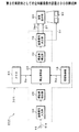
図1は、第1の実施例としての立体画像補正装置100の構成例を示すブロック図である。図1に示す立体画像補正装置100は、液晶シャッタメガネ等を装着した鑑賞者に立体画像を呈示するシステムに適用可能な装置であって、鑑賞者が知覚する立体画像の飛び出し量や引き込み量等を補正する機能を有したものである。立体画像補正装置100は、情報取得部1、視差量検出部2、補正演算部3、視差量補正部4、メモリ5、入力端子6及び出力端子7を有して構成される。
FIG. 1 is a block diagram illustrating a configuration example of a stereoscopic
入力端子6には視差量検出部2が接続され、左眼用画像と右眼用画像から成る立体画像用の画像データDinを入力して当該画像データDinから両眼視差画像の視差量を検出する。ここに、視差量とは、立体画像用の画像情報を基にした表示面上の輻輳角と、知覚する立体表面での輻輳角との差であって、当該表示面上の両眼視差画像のピクセルずれ量と、表示面から鑑賞者の眼に至る標準視距離との間に、ほぼ(ピクセルずれ量)/(標準視距離)で近似されるズレ量をいう。差量検出部2は、同一物体を対象にした左眼用画像と右眼用画像との間に生じるズレ量を検出する。画像データDinは入力端子6を介して視差量検出部2に入力される。視差量検出部2における両眼視差量Dの検出方法については特定のものに限定されない。視差量検出部2には例えば、デジタルシグナルプロセッサ(以下DSPという)が使用される。
A
視差量検出部2には補正演算部3が接続され、視差量検出部2によって検出された両眼視差量Dを表示装置データDdにより調整してダイナミックレンジを補正するようになされる。ここにダイナミックレンジとは、立体画像の飛び出しと引き込みで表現される奥行き量の幅をいう。例えば、表示装置に表示されている立体画像が最も飛び出ている部分で、表示面手前1m、最も引っ込んでいる部分で表示面奥2mにあるように見える場合、そのダイナミックレンジは手前1m、奥2mの計3mとなる。表示装置データDdとは画像表示装置の仕様に関する情報をいう。表示装置データDdには、画像表示装置の表示可能領域を示す表示画面のサイズに関する情報を含む。補正演算部3には例えば、中央処理ユニット(以下CPUという)が使用される。
A
補正演算部3は、情報取得部1において取得した表示装置データDdと視差量検出部2において検出した両眼視差量Dとを基にして、物体の飛び出し量と引き込み量の少なくとも一方のダイナミックレンジを補正するための演算を実行する。例えば、補正演算部3は、視差量検出部2によって検出された両眼視差量Dを表示装置データDdにより調整して飛び出し量と引き込み量の少なくとも一方のダイナミックレンジを補正するための補正情報を演算する(図2参照)。
The
補正演算部3には視差量補正部4が接続され、補正演算部3によって補正された後のダイナミックレンジで表示装置データDdに対応して両眼視差量Dを補正するように動作する。視差量補正部4には出力端子7が接続される。出力端子7に図示しない画像出力部が接続される。
A parallax
視差量補正部4は、補正演算部3で得られた演算結果を基にして、視差量検出部2で得られた元の両眼視差量Dを補正する。例えば、補正演算部3によって演算された補正情報でダイナミックレンジを補正し、補正後のダイナミックレンジと、検出された両眼視差量Dとを組み合わせて両眼視差量Dを補正する。この例で、視差量補正部4は、画像表示装置の表示画面上での両眼視差量Dを補正する際に、立体画像の飛び出し量及び引き込み量の少なくとも一方のダナミックレンジを補正する。視差量補正部4における両眼視差量Dを補正する方法については図5〜図7で説明する。視差量補正部4には例えば、DSPが使用される。
The parallax
補正演算部3には情報取得部1が接続され、鑑賞者が使用している液晶表示パネルや、PDP表示装置等の画像表示装置の仕様に関する情報を取得する。ここで取得される情報は表示装置データDdとなる。この表示装置データDdは、画像表示装置の表示可能領域のサイズや表示可能な解像度に関する情報を含んでいれば、VESA(Video Electronics Standards Association)が規定したEDID(Extended Display Identification Data)を使用しても、独自のフォーマットを使用しても構わない。表示装置データDdにはサイズや解像度等の情報の他に、液晶ディスプレイや、プラズマディスプレイ(PDP)、有機ELディスプレイ等の表示方式を識別する情報を含むことも望ましい。情報取得部1には、キーボードや、マウス等の操作ツールが使用される。
An
この例で、補正演算部3には情報取得部1の他にメモリ5が接続され、情報取得部1から転送される表示装置データDdを格納する。メモリ5には、読み出し専用メモリ(ROM)や、随時情報が書込み読み出し可能なメモリ(RAM)等の他に、EEPROMや、ハードディスク等の不揮発性のメモリが使用される。
In this example, the
メモリ5には、表示装置データDdの他に、コンピュータで読取り可能なシステムプログラムが記述される。システムプログラムは、例えば、同一物体を対象にした左眼用画像と右眼用画像との間に生じるズレ量を両眼視差量Dとし、両眼視差量Dを補正する範囲をダイナミックレンジとし、画像表示装置の仕様に関する情報を表示装置データDdとしたとき、左眼用画像と右眼用画像から成る立体画像用の画像データDinを入力して当該画像データDinから両眼視差量Dを検出するステップと、検出された両眼視差量Dを表示装置データDdにより調整してダイナミックレンジを補正するステップと、補正後のダイナミックレンジで表示装置データDdに対応して両眼視差量Dを補正するステップとを有する内容であり、プログラムデータDpとして格納される。
In the
立体画像における飛び出し量と引き込み量の少なくとも一方のダイナミックレンジと、予め近似的に対応付けられた補正値とを記述したマッピングテーブルを備え、視差量補正部4は、画像表示装置の表示画面上での両眼視差量Dを補正する際にマッピングテーブルを参照して補正値を読み出す。このようなマッピングテーブルを参照すると、立体画像における飛び出し量(L−P)と引き込み量(P−L)の少なくとも一方のダイナミックレンジを離散的に拡大できるようになる。従って、両眼視差量Dを離散的に調整できるので、立体画像の飛び出し量と引き込み量の少なくとも一方を鑑賞者に知覚せしめるようになる。
A parallax
続いて、図2〜図7を参照して、本発明に係る立体画像補正方法について、立体画像補正装置100の動作例を説明する。図2は、両眼視差量Dと対象物体Iの飛び出し量との関係例を示す説明図である。
Next, with reference to FIGS. 2 to 7, an operation example of the stereoscopic
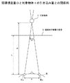
図2に示す両眼視差量Dと対象物体Iの飛び出し量の関係例によれば、画像表示装置の表面IIから鑑賞者IIIの眼IVa及びIVbに至る間の距離をLとし、鑑賞者IIIの瞳孔間距離をdとし、両眼視差画像の視差量をDとし、鑑賞者IIIが知覚する対象物体Iまでの距離をPとしたとき、
D/(L−P)=d/P,(P<L)・・・・(1)
なる関係式から、飛び出し量(L−P)が求められる。図1に示した補正演算部3は、上述の(1)の関係式を演算して、両眼視差量Dを連続的に調整することで、立体画像における飛び出し量(L−P)のダイナミックレンジを連続的に拡大できるようになる。上述の距離Lは、画像表示装置の表面IIの高さをH[m]としたとき、L=3Hが標準視距離として定義されている。なお、図中、Wは画像表示装置の表面IIの幅[m]であり、高さH[m]と共に画面サイズ(H×W)を構成する。画面サイズ(H×W)は表示可能領域を形成する。
According to the example of the relationship between the binocular parallax amount D and the projection amount of the target object I shown in FIG. 2, the distance from the surface II of the image display device to the eyes IVa and IVb of the viewer III is L, and the viewer III When the distance between the pupils is d, the parallax amount of the binocular parallax image is D, and the distance to the target object I perceived by the viewer III is P,
D / (LP) = d / P, (P <L) (1)
The pop-out amount (LP) is obtained from the following relational expression. The
図3は、両眼視差量Dと対象物体Iの引き込み量との関係例を示す説明図である。図3に示す両眼視差量Dと対象物体Iの引き込み量の関係例によれば、画像表示装置の表面IIから鑑賞者IIIの眼に至る間の距離をLとし、鑑賞者IIIの瞳孔間距離をdとし、両眼視差量をDとし、鑑賞者IIIが知覚する対象物体Iまでの距離をPとしたとき、
D/(P−L)=d/P,(P>L)・・・・(2)
なる関係式から、引き込み量(P−L)が求められる。上述の補正演算部3は、(2)の関係式を演算して、立体画像における引き込み量(P−L)のダイナミックレンジを連続的に拡大するので、両眼視差量Dを連続的に調整できるようになる。
FIG. 3 is an explanatory diagram illustrating an example of the relationship between the binocular parallax amount D and the amount of the target object I drawn. According to the example of the relationship between the binocular parallax amount D and the drawing amount of the target object I shown in FIG. 3, the distance from the surface II of the image display device to the eyes of the viewer III is L, and the distance between the pupils of the viewer III When the distance is d, the binocular parallax amount is D, and the distance to the target object I perceived by the viewer III is P,
D / (P−L) = d / P, (P> L) (2)
The amount of pull-in (P−L) is obtained from the following relational expression. The above-described
このような両眼視差量Dと飛び出し量や引き込み量等の間で相関する、(1)、(2)の関係式が成り立っており、両眼視差量Dを補正することで、対象物体Iの飛び出し量や、引き込み量等を調整できるようになる。また、(1)、(2)の関係式を用いると、補正演算部3は、立体画像における飛び出し量(L−P)と引き込み量(P−L)の少なくとも一方のダイナミックレンジを連続的に拡大できるようになる。従って、両眼視差量Dを連続的に調整できるので、立体画像の飛び出し量と引き込み量の少なくとも一方を鑑賞者に十分かつ円滑に知覚せしめるようになる。
The relational expressions (1) and (2) that correlate between the binocular parallax amount D and the pop-out amount, the pull-in amount, and the like are established, and the target object I is corrected by correcting the binocular parallax amount D. The amount of popping out and the amount of pulling in can be adjusted. When the relational expressions (1) and (2) are used, the
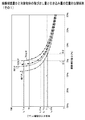
図4は、%両眼視差量Dと対象物体の飛び出し量と引き込み量の定量的な関係例(その1)を示すグラフ図である。図4に示す縦軸は対象物体Iまでの距離L[m]であり、対数目盛で示している。横軸は百分率[%]で示した両眼視差量D(以下で%両眼視差量Dという)であり、%両眼視差量Dは、画像表示装置の表示可能領域の幅Wに対する相対量を百分率[%]で規定したものである。以下に、画像の大きさを画像表示装置の表示可能領域のサイズに合わせた上で、両眼視差画像を表示する場合を説明する。 FIG. 4 is a graph showing an example (part 1) of a quantitative relationship between the% binocular parallax amount D, the pop-out amount of the target object, and the pull-in amount. The vertical axis shown in FIG. 4 is the distance L [m] to the target object I, which is shown on a logarithmic scale. The horizontal axis is the binocular parallax amount D (hereinafter referred to as% binocular parallax amount D) expressed as a percentage [%], and the% binocular parallax amount D is a relative amount with respect to the width W of the displayable area of the image display device. Is specified as a percentage [%]. Hereinafter, a case where a binocular parallax image is displayed after the size of the image is matched with the size of the displayable area of the image display device will be described.
図4に示す実線に菱形印は、700インチのスクリーンにおける両眼視差量Dと対象物体Iの飛び出し量等との定量的な関係例を示す特性曲線である。実線に四角印は、100インチの画像表示装置における両眼視差量Dと対象物体Iの飛び出し量等との定量的な関係例を示す特性曲線である。実線に△印は、70インチの画像表示装置における両眼視差量Dと対象物体Iの飛び出し量等との定量的な関係例を示す特性曲線である。 A rhombus mark on the solid line shown in FIG. 4 is a characteristic curve showing an example of a quantitative relationship between the binocular parallax amount D and the protrusion amount of the target object I on a 700-inch screen. A square mark on the solid line is a characteristic curve showing an example of a quantitative relationship between the binocular parallax amount D and the projection amount of the target object I in a 100-inch image display device. A solid line represents a characteristic curve showing an example of a quantitative relationship between the binocular parallax amount D and the amount of protrusion of the target object I in a 70-inch image display device.
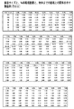
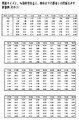
実線に×印は、40インチの画像表示装置における%両眼視差量Dと対象物体Iの飛び出し量等との定量的な関係例を示す特性曲線である。なお、図16〜図20において、700インチ、100インチ、70インチ及び40インチを含む7種類の画像表示装置についての%両眼視差量Dと対象物体の飛び出し量と引き込み量の定量的な関係例を示すグラフ図及び、知覚される対象物体までの距離を表図にまとめている。 The solid line is a characteristic curve showing an example of a quantitative relationship between the% binocular parallax amount D and the amount of protrusion of the target object I in a 40-inch image display device. 16 to 20, the quantitative relationship between the% binocular parallax amount D, the projection amount of the target object, and the pull-in amount for seven types of image display devices including 700 inches, 100 inches, 70 inches, and 40 inches. A graph showing an example and the distance to the perceived target object are summarized in a table.
図4において、例えば、700インチのスクリーンを想定して制作された画像に関して、鑑賞者IIIに所望の対象物体Iの飛び出しや引き込み等の奥行きを知覚させるように、%両眼視差量DがD1(0%)からD2(5%)の間になるようにダイナミックレンジを設定したとする。その場合、700インチの表示画面で鑑賞する鑑賞者IIIは、対象物体Iが距離L1aからL2aの間に存在していると知覚することになる。 In FIG. 4, for example, for an image produced assuming a 700-inch screen, the% binocular parallax amount D is D1 so that the viewer III perceives the depth of the desired target object I popping out or being pulled in. Assume that the dynamic range is set to be between (0%) and D2 (5%). In that case, the viewer III who appreciates on the 700-inch display screen perceives that the target object I exists between the distances L1a and L2a.
次に、表示可能領域が40インチの画像表示装置で同一の両眼視差画像を鑑賞する場合、両眼視差画像に付けられている%両眼視差量Dは、表示可能領域の幅で相対的に規定されているため、%両眼視差量DがD1からD2の間となる。その場合、40インチの表示画面で鑑賞する鑑賞者IIIは、対象物体Iが距離L1bからL2bに存在していると知覚することになる。ここで図4の関係(比例縮小)から、式(3)の関係が成り立つことが分かる。
|L2a−L1a|>|L2b−L1b| ・・・・(3)
このように、両眼視差画像の大きさを画像表示装置の表示可能領域の画面サイズに適合させるだけでは、画像制作者が意図した飛び出し量や引き込み量が反映されず、奥行き方向が圧縮された画像が表示されてしまう。
Next, when viewing the same binocular parallax image on an image display device having a displayable area of 40 inches, the% binocular parallax amount D attached to the binocular parallax image is relative to the width of the displayable area. Therefore, the% binocular parallax amount D is between D1 and D2. In that case, the viewer III who appreciates on the 40-inch display screen perceives that the target object I exists from the distance L1b to L2b. Here, it can be seen from the relationship (proportional reduction) in FIG. 4 that the relationship of Equation (3) holds.
| L2a-L1a |> | L2b-L1b | (3)
In this way, just adjusting the size of the binocular parallax image to the screen size of the displayable area of the image display device does not reflect the pop-out amount or pull-in amount intended by the image creator, and the depth direction is compressed. An image is displayed.
そこで、本発明に係る立体画像の補正方法によれば、画像制作者が意図した飛び出し量や引き込み量等が反映されるように、画像表示装置の表示可能領域の画面サイズに合わせて%両眼視差量Dを補正するようにした。その補正方法には、画像制作者の意図する両眼視差量Dを正確に再現する方法と、飛び出し量と引き込み量のダイナミックレンジを拡大する方法との2通りが挙げられる。 Therefore, according to the method for correcting a stereoscopic image according to the present invention,% binocular according to the screen size of the displayable area of the image display device so that the pop-out amount or the pull-in amount intended by the image creator is reflected. The parallax amount D is corrected. There are two correction methods: a method of accurately reproducing the binocular parallax amount D intended by the image producer, and a method of expanding the dynamic range of the pop-out amount and the pull-in amount.
図5は、%両眼視差量Dと対象物体の飛び出し量と引き込み量の定量的な関係例(その2)を示すグラフ図である。図5において、縦軸は物体までの距離L[m]であり、対数目盛で示している。横軸は%両眼視差量Dであり、百分率[%]で示している。 FIG. 5 is a graph showing an example (part 2) of a quantitative relationship between the% binocular parallax amount D, the pop-out amount of the target object, and the pull-in amount. In FIG. 5, the vertical axis represents the distance L [m] to the object, which is shown on a logarithmic scale. The horizontal axis represents% binocular parallax amount D, and is expressed as a percentage [%].
まず、図4に示した例を基にして、画像制作者の意図する両眼視差量Dを正確に再現する場合、例えば、700インチのスクリーンを想定して制作された画像に関して、%両眼視差量Dを最大D1(0%)に設定すると、鑑賞者IIIは対象物体Iが距離L1aからL2aの間に存在していると知覚する。 First, based on the example shown in FIG. 4, when the binocular parallax amount D intended by the image producer is accurately reproduced, for example, for an image produced assuming a 700-inch screen,% binocular When the parallax amount D is set to the maximum D1 (0%), the viewer III perceives that the target object I exists between the distances L1a and L2a.
対象物体Iが距離L1aからL2aの間に存在していると、鑑賞者IIIに知覚させるためには、図5に示す補正目標値を設定してその補正目標値へダイナミックレンジを移動する方法を採る。この方法によれば、画像表示装置の表示可能領域の画面サイズに応じた両眼視差量Dを両眼視差画像に設けるようになされる。例えば、画像表示装置の表示可能領域の画面サイズが70インチの場合は、両眼視差量DがD1aからD2aの間になるように、図1に示した補正演算部3がダイナミックレンジを補正するようになされ、画像表示装置の表示可能領域の画面サイズが40インチの場合は、両眼視差量DがD1bからD2bの間になるように、補正演算部3がダイナミックレンジを補正するようになされる。
In order for the viewer III to perceive that the target object I exists between the distances L1a and L2a, a method of setting the correction target value shown in FIG. 5 and moving the dynamic range to the correction target value is shown. take. According to this method, the binocular parallax amount D corresponding to the screen size of the displayable area of the image display device is provided in the binocular parallax image. For example, when the screen size of the displayable area of the image display device is 70 inches, the
次に、図4に示した例を基にして、飛び出し量と引き込み量のダイナミックレンジを拡大する方法について説明する。図6は、両眼視差量Dと対象物体の飛び出し量と引き込み量の定量的な関係例(その3)を示すグラフ図である。図6において、縦軸は対象物体Iまでの距離L[m]であり、対数目盛で示している。横軸は両眼視差量Dであり、百分率[%]で示している。 Next, a method for expanding the dynamic range of the pop-out amount and the pull-in amount will be described based on the example shown in FIG. FIG. 6 is a graph showing an example (part 3) of a quantitative relationship between the binocular parallax amount D, the protrusion amount of the target object, and the pull-in amount. In FIG. 6, the vertical axis represents the distance L [m] to the target object I, which is shown on a logarithmic scale. The horizontal axis represents the binocular parallax amount D, and is expressed as a percentage [%].
例えば、700インチのスクリーンを想定して制作された画像に関して、その画像が有する最大の両眼視差量D=D2−D1に設定すると、鑑賞者IIIは対象物体Iが距離L1aからL2aの間に存在していると知覚する。ここで、鑑賞者IIIに、より一層の飛び出し感を与えたい場合、対象物体Iまでの距離Pが距離L1aからL3a(L3a<L2a)の間に存在するようにダイナミックレンジを設定するようになされる。 For example, regarding an image produced assuming a 700-inch screen, if the maximum binocular parallax amount D = D2−D1 of the image is set, the viewer III has the target object I between the distances L1a and L2a. Perceived to exist. Here, when it is desired to give the viewer III a feeling of further popping out, the dynamic range is set so that the distance P to the target object I exists between the distances L1a and L3a (L3a <L2a). The
図6に示した飛び出し量と引き込み量のダイナミックレンジを拡大する方法を採ると、画像表示装置の表示可能領域の画面サイズが70インチの場合は、両眼視差量DがD1aからD3aの間になるように、図1に示した補正演算部3がダイナミックレンジを補正するように演算される。また、画像表示装置の表示可能領域の画面サイズが40インチの場合は、両眼視差量DがD1bからD3bの間になるように、補正演算部3がダイナミックレンジを補正するようになされる。
When the method of expanding the dynamic range of the pop-out amount and the pull-in amount shown in FIG. 6 is used, when the screen size of the displayable area of the image display device is 70 inches, the binocular parallax amount D is between D1a and D3a. In this way, the
ダイナミックレンジを補正する演算は、図1に示した補正演算部3が式(1)及び式(2)で表される関係式を用いて実行する。補正演算部3は、画像制作者が意図する飛び出し量や引き込み量等に相当する両眼視差量Dを計算する。この計算によって、鑑賞者IIIが使用する画像表示装置の表示可能領域の画面サイズであっても、画像制作者が意図する飛び出し量や引き込み量を実現できるようになる。
The calculation for correcting the dynamic range is executed by the
なお、画像表示装置の表示画面上での両眼視差画像の視差量Dを補正する際に、画像表示装置の画面サイズ毎に、飛び出し量や引き込み量と両眼視差量Dとの関係を予めテーブル化しておき、テーブルに格納された値に基づいて両眼視差量Dを計算し、所望の飛び出し量や引き込み量等を実現しても良い。 Note that when correcting the parallax amount D of the binocular parallax image on the display screen of the image display device, the relationship between the pop-out amount and the pull-in amount and the binocular parallax amount D is previously determined for each screen size of the image display device. A binocular parallax amount D may be calculated based on values stored in the table, and a desired pop-out amount, pull-in amount, and the like may be realized.
例えば、立体画像における飛び出し量と引き込み量の少なくとも一方のダイナミックレンジと、予め近似的に対応付けられた値を記述したマッピングテーブルを準備する。このようなマッピングテーブルを参照すると、立体画像における飛び出し量(L−P)と引き込み量(P−L)の少なくとも一方のダイナミックレンジを離散的に拡大して補正できるようになる。従って、立体画像の飛び出し量と引き込み量の少なくとも一方を鑑賞者に十分に知覚せしめるようになる。 For example, a mapping table is prepared in which a dynamic range of at least one of the pop-out amount and the pull-in amount in the stereoscopic image is described in advance in a roughly associated value. With reference to such a mapping table, at least one of the dynamic range of the pop-out amount (L-P) and the pull-in amount (P-L) in the stereoscopic image can be corrected by being discretely expanded. Therefore, the viewer can sufficiently perceive at least one of the pop-out amount and the pull-in amount of the stereoscopic image.
また、画面サイズが40インチ以上である場合は、横1920ピクセル、縦1080ラインのHD(High Definition)解像度を有していることが多いが、画面サイズが40インチ未満である場合は、横1366ピクセル、縦768ラインの解像度しか持たない場合がある。一般に、標準視距離は、画面サイズと解像度によって決まるため、図4から図6に示したように、画面サイズによって描かれる、%両眼視差量Dと対象物体の飛び出し量と引き込み量の定量的な関係を示す特性曲線の形状は異なってくる。 Further, when the screen size is 40 inches or more, it often has HD (High Definition) resolution of 1920 pixels in width and 1080 lines in length, but when the screen size is less than 40 inches, 1366 in width. It may have only a resolution of 768 lines in pixels, length. In general, since the standard viewing distance is determined by the screen size and resolution, as shown in FIGS. 4 to 6, as shown in FIG. 4 to FIG. 6, the quantitative amount of the binocular parallax amount D, the pop-out amount of the target object, and the pull-in amount are drawn. The shape of the characteristic curve that shows the relationship is different.
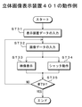
図7は、立体画像補正装置100の動作例を示すフローチャートである。この実施例で、同一物体を対象にした左眼用画像と右眼用画像との間に生じるズレ量を%両眼視差量Dとし、%両眼視差量Dを補正する範囲をダイナミックレンジとし、画像表示装置の仕様に関する情報を表示装置データDdとする。表示装置データDdには、画像表示装置の表示可能領域を示す画面サイズと解像度に関する情報が含まれる。
FIG. 7 is a flowchart illustrating an operation example of the stereoscopic
これらを立体画像補正条件にして、立体画像補正装置100では、図7のフローチャートのステップST1で情報取得部1が画像表示装置の仕様を取得して表示装置データDdを入力する。例えば、情報取得部1は、鑑賞者IIIが使用している画像表示装置の表示可能領域の画面サイズや表示可能な解像度に関する情報等を取得してメモリ60に格納する。これらの画面サイズや情報等に関しては、VESAが規定したEDIDを使用しても、独自のフォーマットを使用しても構わない。表示装置データDdには、液晶ディスプレイや、プラズマディスプレイ、有機ELディスプレイ等の表示方式を識別する情報が含まれていてもよい。
Under these three-dimensional image correction conditions, in the three-dimensional
次に、立体画像補正装置100は、ステップST2で左眼用画像と右眼用画像から成る立体画像用の画像データDinを入力する。画像データDinは、入力端子6を介して視差量検出部2に入力される。その後、ステップST3で視差量検出部2は当該画像データDinから両眼視差量Dを検出する。両眼視差量Dの検出方法は一般に知られている方法を使用すればよく、その方式は特定のものに限定されない。この時点で付加されている%両眼視差量Dは、ある特定の画面サイズの画像表示装置を意図して制作者が設定したものであり、それ以外の画面サイズの画像表示装置では、物体の飛び出し量や引き込み量が制作者の意図とは異なっている。
Next, in step ST2, the stereoscopic
ステップST4で両眼視差量Dの検出を全て終了したかを判定する。両眼視差量Dの検出を全部終了していない場合は、ステップST2に戻って上述した処理を繰り返す。両眼視差量Dの検出を全部終了した場合は、ステップST5に移行する。 In step ST4, it is determined whether all the binocular parallax amounts D have been detected. If the detection of the binocular parallax amount D has not been completed, the process returns to step ST2 and the above-described processing is repeated. When all the detection of the binocular parallax amount D is completed, the process proceeds to step ST5.
ステップST5で補正演算部3は、先に検出された両眼視差量Dを表示装置データDdにより調整してダイナミックレンジを補正する。例えば、ステップST1において取得した画像表示装置の表示可能領域の画面サイズや、表示可能な解像度に関する情報等と、ステップST3で検出された両眼視差量Dとを基にして飛び出し量と引き込み量の少なくとも一方のダイナミックレンジを補正するための補正情報を演算する。ここに演算された補正情報でダイナミックレンジを補正する。
In step ST <b> 5, the
ダイナミックレンジを補正するための演算において、画像表示装置の表示可能領域の画面サイズや、表示可能な解像度に関する情報等から得られる、画像表示装置の表面IIから鑑賞者IIIの眼IVa,IVbに至る間の標準視距離をLとし、鑑賞者IIIの瞳孔間距離をdとし、両眼視差量をDとし、鑑賞者IIIが知覚する対象物体Iまでの距離をPとしたとき、図2で説明した式(1)の関係が成り立ち、図3で説明した式(2)の関係が成り立つ。
In the calculation for correcting the dynamic range, from the surface II of the image display device obtained from the screen size of the displayable area of the image display device, information on the displayable resolution, etc., to the eyes IVa and IVb of the
これらの関係式から、補正演算部3は飛び出し量(L−P)及び、引き込み量(P−L)を求める。このような(1)、(2)の関係式を用いると、立体画像における飛び出し量(L−P)と引き込み量(P−L)の少なくとも一方のダイナミックレンジを連続的に拡大して補正できるようになる。なお、図4には、Lを標準視距離、瞳孔間距離dを65mmとし、画像表示装置の表示可能領域の画面サイズを700インチ、100インチ、70インチ及び40インチとした場合の定量的な関係例を示している。
From these relational expressions, the
そして、ステップST6で視差量補正部4は、ステップST5で得られた演算結果と表示装置データDdとを基にしてダイナミックレンジが補正されたものとなるように両眼視差量Dを補正する。視差量補正部4は、補正後のダイナミックレンジと両眼視差量Dとを組み合わせて、ステップST3で検出された元の両眼視差量Dを補正する(図5及び図6参照)。
In step ST6, the parallax
そして、ステップST7で補正後の画像データDoutを出力する。補正後の画像データDoutは、鑑賞者IIIが使用する画像表示装置において、画像制作者が意図した物体の飛び出し量や引き込み量が表現されるように両眼視差量Dを調整されたものである。その後、ステップST8で視差量補正部4は視差量補正が終了したかを判定する。この判定では、ステップST6における両眼視差量Dの補正が終了したかどうかを検出することで実行される。両眼視差量Dの補正が終了していない場合はステップST6へ戻り、両眼視差量Dの補正が終了している場合は補正済みの両眼視差画像を出力する。
In step ST7, the corrected image data Dout is output. The corrected image data Dout is obtained by adjusting the binocular parallax amount D so that the amount of popping out and pulling in the object intended by the image producer is expressed in the image display device used by the viewer III. . Thereafter, in step ST8, the parallax
このように第1の実施例としての立体画像補正装置100及び立体画像補正方法によれば、視差量検出部2によって検出された両眼視差量Dを表示装置データDdにより調整して立体画像の飛び出し量と引き込み量の少なくとも一方のダイナミックレンジを補正する補正演算部3を備え、補正後のダイナミックレンジで表示装置データDdに対応して両眼視差量Dを補正するようになされる。
As described above, according to the stereoscopic
従って、対象物体Iの飛び出し量や、引き込み量等を表示装置データDdに対応して調整できるようになる。しかも、画像表示装置の仕様が異なる場合であっても、立体画像の飛び出し量と引き込み量の少なくとも一方を鑑賞者が好ましいと感じる飛び出し画像や奥行き画像を実現できるのみならず、画像制作者が意図する飛び出し画像や引き込み画像を正確に表現できるようになる。これにより、制作者の意図に沿った立体画像を鑑賞者に知覚せしめることが可能となる。 Accordingly, the pop-out amount, the pull-in amount, and the like of the target object I can be adjusted according to the display device data Dd. Moreover, even if the specifications of the image display device are different, it is possible not only to realize a pop-out image and a depth image that the viewer feels preferable for at least one of the pop-up amount and pull-in amount of the stereoscopic image, This makes it possible to accurately express the pop-up image and the pull-in image. This makes it possible for the viewer to perceive a stereoscopic image according to the creator's intention.
この実施例で、画像表示装置の仕様を取得するステップST1は、立体画像用の画像データDinを入力するステップST2の前に実行する場合について説明したが、これに限られることはなく、ステップST1で取得した表示装置データDdは、ステップST5のダイナミックレンジの補正演算で使用するため、ステップST5の前に実行されるのであれば、ステップST2以降のステップST4までのどの段階で実行する場合であってもよい。 In this embodiment, the step ST1 for obtaining the specification of the image display device has been described as being executed before the step ST2 for inputting the image data Din for stereoscopic images. However, the present invention is not limited to this. Since the display device data Dd acquired in step ST5 is used in the dynamic range correction calculation in step ST5, if it is executed before step ST5, it can be executed at any stage from step ST2 to step ST4. May be.
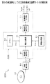
図8は、第2の実施例としての立体画像表示装置200の構成例を示すブロック図である。図8に示す立体画像表示装置200は、立体画像用の画像データDoutに基づいて映像を表示するものであって、入力端子16、立体画像補正ユニット101、画像表示部80及び液晶シャッタメガネ90を有して構成される。
FIG. 8 is a block diagram illustrating a configuration example of a stereoscopic
入力端子16には、左眼用画像と右眼用画像から成る立体画像用の画像データDinが入力される。この画像データDinは、画像表示部80に2次元の映像を表示する第1の2次元画像信号と、2次元の映像に対して奥行きを表現する第2の2次元画像信号から構成される。入力端子16には立体画像補正ユニット101が接続され、立体画像の飛び出し量と引き込み量の少なくとも一方のダイナミックレンジを補正し、補正後のダイナミックレンジで表示装置データDdに対応して両眼視差量Dを補正するようになされる。立体画像補正ユニット101には、第1の実施例で説明した立体画像補正装置100が応用される。
The
立体画像補正ユニット101は、情報取得部10、視差量検出部20、補正演算部30、視差量補正部40、画像信号入力部50、メモリ60及び画像信号出力部70を有して構成される。画像信号入力部50は上述の入力端子16に接続され、左眼用画像と右眼用画像から成る立体画像用の画像データDinを入力するようになされる。画像データDinは電気信号の形態又は光通信の形態で、外部の立体画像再生装置や、デジタル放送設備等から当該立体画像表示装置200の画像信号入力部50へ供給される。
The stereoscopic
画像信号入力部50には視差量検出部20が接続され、左眼用画像と右眼用画像から成る立体画像用の画像データDinを入力して当該画像データDinから両眼視差量Dを検出する。両眼視差量の検出方法については第1の実施例で説明した通りである。両眼視差量Dの検出方法は特定のものに限定されるものではない。視差量検出部20には第1の実施例と同様にして、DSPが使用される。
A
視差量検出部20には補正演算部30が接続され、視差量検出部20によって検出された両眼視差量Dを表示装置データDdにより調整して、飛び出し量と引き込み量の少なくとも一方のダイナミックレンジを補正するための補正情報を演算する(図2、図3参照)。補正演算部30には第1の実施例と同様にして、CPUが使用される。補正演算部30では、情報取得部10において取得した画像表示部80の情報と、視差量検出部20において検出した両眼視差量Dを基にして、対象物体Iの飛び出し量と引き込み量の少なくとも一方のダイナミックレンジを補正するための演算を行う。
A
補正演算部30には視差量補正部40が接続され、補正演算部30によって補正された後のダイナミックレンジで表示装置データDdに対応して両眼視差量Dを補正する。視差量補正部40は、例えば、補正演算部30によって演算された補正情報でダイナミックレンジを補正し、補正後のダイナミックレンジと、検出された両眼視差量Dとを組み合わせて両眼視差量Dを補正する。この例でも、視差量補正部40は、画像表示部80の表示画面上での両眼視差量Dを補正する際に、立体画像の飛び出し量及び引き込み量の少なくとも一方をダイナミックレンジに設定する。視差量補正部40における両眼視差量Dを補正する方法については図5〜図7で説明した通りである。視差量補正部40にもDSPが使用される。
A parallax
この例でも、補正演算部30には情報取得部10が接続され、飛び出し量と引き込み量の少なくとも一方のダイナミックレンジをマニュアル設定するため表示装置データDdを入力される。補正演算部30には情報取得部10の他にメモリ60が接続され、画像表示部80の仕様を示す表示装置データDdを格納する。メモリ60には、鑑賞者IIIが使用している画像表示部80の仕様に関する情報を格納する。この情報は、画像表示部80の表示可能領域の画面サイズや表示可能な解像度に関する情報を含んでいれば、VESAが規定したEDIDであっても、独自のフォーマットであっても構わない。また、表示装置データDdには、液晶ディスプレイや、プラズマディスプレイ、有機ELディスプレイ等の画像表示部80の表示方式を識別する情報が含まれていてもよい。
Also in this example, the
メモリ60には、第1の実施例と同様にして、読み出し専用メモリ(ROM)や、随時情報が書込み読み出し可能なメモリ(RAM)等の他に、EEPROMや、ハードディスク等の不揮発性のメモリが使用される。メモリ60には、表示装置データDdの他に、コンピュータで読取り可能なシステムプログラムが記述される。システムプログラムについては第1の実施例で説明した通りである。
As in the first embodiment, the
上述の視差量補正部40には画像信号出力部70が接続され、画像表示部80に視差量補正後の立体画像用の画像データDoutを出力する。画像データDoutは、両眼視差量Dが補正された両眼視差画像を表示するためデータであって、画像信号出力部70から画像表示部80へ出力される。画像信号出力部70は、画像データDoutの他に水平同期信号や、垂直同期信号等の画像表示制御信号Sfを画像表示部80へ出力する。
An image
画像信号出力部70には、表示手段の一例を構成する画像表示部80が接続され、両眼視差量Dが補正された立体画像呈示用の画像データDoutや、画像表示制御信号Sfに基づいて立体画像呈示用の映像を表示する。例えば、画像表示部80は、フィールドシーケンシャルと呼ばれる映像フォーマットの画像データDoutに基づいて鑑賞者IIIが知覚できる形態で、時系列に左眼用映像→右眼用映像→左眼用映像→右眼用映像・・・というタイミングで交互に左右視差画像を表示画面上に表示する。両眼視差量Dを補正する方法は、第1の実施例で説明した通りである。画像表示部80には液晶ディスプレイ装置や、プラズマディスプレイ装置、有機ELディスプレイ装置等が使用される。
An
画像信号出力部70には画像表示部80の他に液晶シャッタメガネ90が接続され、画像表示制御信号Sfの中の垂直同期信号Svに基づいて左眼ON/右眼OFF→左眼OFF/右眼ON→左眼ON/右眼OFF・・と交互にシャッタON/OFF動作を繰返すようになされる。シャッタON/OFF動作は、左眼用画像と右眼用画像との表示切り替えに同期して実行される。これらの構成により、鑑賞の左眼には左眼用映像のみが、右眼には右眼用映像のみを入力させることができ、3次元立体映像を鑑賞できるようになる。
In addition to the
続いて、立体画像表示装置200の動作例について説明する。図9は、立体画像表示装置200の動作例を示すフローチャートである。この実施例で、立体画像用の画像情報を基にした表示面上の輻輳角と、知覚する立体表面での輻輳角との差であって、当該表示面上の両眼視差画像のピクセルずれ量と、前記表示面から鑑賞者の眼に至る標準視距離との間に、ほぼ(ピクセルずれ量)/(標準視距離)で近似されるズレ量を視差量とし、立体画像の飛び出しと引き込みで表現される奥行き量の幅をダイナミックレンジとし、表示装置の仕様に関する情報を表示装置情報としたとき、画像表示部80の仕様に関する情報を表示装置データDdとする。表示装置データDdには、画像表示部80の表示可能領域を示す画面サイズと解像度に関する情報が含まれる。
Subsequently, an operation example of the stereoscopic
これらを立体画像表示条件にして、立体画像表示装置200では、図9のフローチャートのステップST11で情報取得部10が画像表示部80で、対象物体の飛び出し量や、引き込み量等の仕様を取得して表示装置データDdを入力する。例えば、情報取得部10は、鑑賞者IIIが鑑賞している画像表示部80の表示可能領域の画面サイズや表示可能な解像度に関する情報等を取得してメモリ60に格納する。これらの画面サイズや情報等に関しては、VESAが規定したEDIDを使用しても、独自のフォーマットを使用しても構わない。表示装置データDdには、液晶ディスプレイや、プラズマディスプレイ、有機ELディスプレイ等の表示方式を識別する情報が含まれる。
Under these three-dimensional image display conditions, in the three-dimensional
次に、立体画像表示装置200は、ステップST12で、例えば、フィールドシーケンシャルの映像フォーマットの左眼用画像と右眼用画像から成る立体画像用の画像データDinを入力する。画像データDinは、入力端子16を介して画像信号入力部50を介して視差量検出部20に入力される。その後、ステップST13で視差量検出部20は当該画像データDinから両眼視差量Dを検出する。両眼視差量Dの検出方法は第1の実施例で説明した通りである。この時点で付加されている両眼視差量Dは、ある特定の画面サイズの画像表示部80を意図して制作者が設定したものであり、それ以外の画面サイズの画像表示部80では、物体の飛び出し量や引き込み量が制作者の意図とは異なっている。
Next, in step ST12, the stereoscopic
ステップST14で視差量検出部20は両眼視差量Dの検出を全て終了したかを判定する。両眼視差量Dの検出を全部終了していない場合は、ステップST12に戻って上述した処理を繰り返す。両眼視差量Dの検出を全部終了した場合は、ステップST15に移行する。
In step ST14, the parallax
ステップST15で補正演算部30は、先に検出された両眼視差量Dを表示装置データDdにより調整してダイナミックレンジを補正する。例えば、ステップST11において取得した画像表示部80の表示可能領域の画面サイズや、表示可能な解像度に関する情報等と、ステップST13で検出された両眼視差量Dとを基にして飛び出し量と引き込み量の少なくとも一方のダイナミックレンジを補正するための補正情報を演算する。ここに演算された補正情報でダイナミックレンジを補正する。
In step ST15, the
ダイナミックレンジを補正するための演算において、画像表示部80の表示可能領域の画面サイズや、表示可能な解像度に関する情報等から得られる、画像表示部80の表面から鑑賞者の眼に至る間の標準視距離と、鑑賞者の瞳孔間距離と、両眼視差量Dとし、鑑賞者が知覚する対象物体までの距離から、図2で説明したような式(1)及び、図3で説明した式(2)が成り立つ。これらの関係式から、第1の実施例と同様にして補正演算部30は飛び出し量及び、引き込み量を求める。このような(1)、(2)の関係式を用いると、立体画像における飛び出し量と引き込み量の少なくとも一方のダイナミックレンジを連続的に拡大して補正できるようになる。
In the calculation for correcting the dynamic range, the standard from the surface of the
その後、ステップST16で視差量補正部40は、ステップST15で得られた演算結果と表示装置データDdとを基にしてダイナミックレンジが補正されたものとなるように両眼視差量Dを補正する。視差量補正部4は、補正後のダイナミックレンジと両眼視差量Dとを組み合わせて、ステップST13で検出された元の両眼視差量Dを補正する(図5及び図6参照)。
After that, in step ST16, the parallax
そして、ステップST17で画像信号出力部70は、補正後の画像データDoutを画像表示部80へ出力すると共に、垂直同期信号Svを液晶シャッタメガネ90に出力する。補正後の画像データDoutは、鑑賞者IIIが使用する画像表示部80において、画像制作者が意図した物体の飛び出し量や引き込み量が表現されるように両眼視差量Dを調整されたものである。
In step ST <b> 17, the image
ステップST18で画像表示部80は、両眼視差量Dが補正された立体画像呈示用の画像データDoutや、画像表示制御信号Sfに基づいて立体画像呈示用の映像を表示する。
これに並行してステップST19で液晶シャッタメガネ90は、垂直同期信号Svに基づいて左眼ON/右眼OFF→左眼OFF/右眼ON→左眼ON/右眼OFF・・と交互にシャッタON/OFF動作を繰返すようになされる。シャッタON/OFF動作は、左眼用画像と右眼用画像との表示切り替えに同期して実行される。これらの構成により、鑑賞者の左眼には左眼用映像のみが、右眼には右眼用映像のみを入力させることができ、3次元立体映像を鑑賞できるようになる。
In step ST18, the
In parallel with this, in step ST19, the liquid
その後、ステップST20で当該立体画像表示装置200は立体画像表示処理を終了するかを判定する。この判定では、例えば、電源オフ情報を検出して立体画像表示処理の終了か否かを判別する。電源オフ情報が検出されない場合は、ステップST12に戻って上述した処理を繰り返すようになされる。電源オフ情報が検出された場合に立体画像表示処理を終了する。
Thereafter, in step ST20, the stereoscopic
このように第2の実施例としての立体画像表示装置200によれば、立体画像補正ユニット101に本発明に係る立体画像補正装置が応用されるので、対象物体の飛び出し量や、引き込み量等を表示装置データDdに対応して調整できるようになる。従って、立体画像表示装置200の仕様が異なる場合であっても、鑑賞者が好ましいと感じる飛び出し量や引き込み量を実現できるのみならず、画像制作者が意図する飛び出し量や引き込み量等を正確に表現できるようになる。これにより、画像制作者の意図に沿った立体画像を鑑賞者に知覚せしめることが可能となる。鑑賞者は画像制作者の意図に沿った立体画像を十分に知覚できるようになる。
As described above, according to the stereoscopic
図10は、第3の実施例としての立体画像再生装置300の構成例を示すブロック図である。立体画像再生装置300は、情報再生部51及び立体画像補正ユニット102を有して構成される。
FIG. 10 is a block diagram illustrating a configuration example of a stereoscopic
情報再生部51は、再生手段の一例を構成し、左眼用画像と右眼用画像から成る立体画像用の画像情報を再生するものである。情報再生部51にはBlu−ray(R)やDVDディスク等の情報記録媒体が装着される。情報記録媒体には、立体画像用の画像データDinが記録されている。画像データDinは、液晶ディスプレイや、プラズマディスプレイ、有機ELディスプレイ等の画像表示装置に2次元の映像を表示するための第1の2次元画像信号と、2次元の映像の奥行きを表示する第2の2次元画像信号から構成される。
The
情報再生部51は、図示せずも、光ピックアップ、スピンドルモータ、サーボ回路、スピンドル制御回路、復調回路及び誤り訂正回路等を有してデータ読み出し回路を構成する。データ読み出し回路には、ストリーム分離部やデコード部が設けられ、ビデオストリーム(以下画像データDinという)や音声ストリームが分離される。そして、情報記録媒体がDVDである場合は、MPEG2 PS(プログラムストリーム)がデコードされる。情報記録媒体がBlu−rayである場合は、MPEG2 Videoや、MPEG4 AVC等をデコードするようになされる。
Although not shown, the
情報再生部51には立体画像補正ユニット102が接続され、情報再生部51によって再生された画像データDinの両眼視差量Dを補正して視差量補正後の立体画像用の画像データDoutを出力するようになされる。画像データDinは、左眼用画像と右眼用画像から成る。立体画像補正ユニット102は、立体画像の飛び出し量と引き込み量の少なくとも一方のダイナミックレンジを補正し、表示装置データDdを基にしてダイナミックレンジが補正されたものとなるよう、両眼視差量Dを補正する。立体画像補正ユニット102には、第1の実施例で説明した立体画像補正装置100が応用される。
A stereoscopic
立体画像補正ユニット102は、情報取得部11、視差量検出部21、補正演算部31、視差量補正部41、画像信号入力部50、メモリ60及び画像信号出力部71を有して構成される。上述の情報再生部51には視差量検出部21が接続され、左眼用画像と右眼用画像から成る立体画像用の画像データDinを入力して当該画像データDinから両眼視差量Dを検出する。両眼視差量Dの検出方法については第1の実施例で説明した通りである。両眼視差量Dの検出方法は特定のものに限定されるものではない。視差量検出部21には第1の実施例と同様にして、DSPが使用される。
The stereoscopic
視差量検出部21には補正演算部31が接続され、視差量検出部21によって検出された両眼視差量Dを表示装置データDdにより調整して、飛び出し量と引き込み量の少なくとも一方のダイナミックレンジを補正する(図2、図3参照)。補正演算部31には第1及び第2の実施例と同様にして、CPUが使用される。補正演算部31では、情報取得部11において取得した画像表示装置の情報と、視差量検出部21において検出した両眼視差量Dを基にして、対象物体Iの飛び出し量と引き込み量の少なくとも一方のダイナミックレンジを補正するための演算を行う。
A
補正演算部31には視差量補正部41が接続され、視差量補正部41は補正演算部31における演算結果と、表示装置データDdとを基にしてダイナミックレンジが補正されたものとなるよう、両眼視差量Dを補正する。視差量補正部41は、例えば、補正演算部31によって演算された補正情報でダイナミックレンジを補正し、補正後のダイナミックレンジと、検出された両眼視差量Dとを組み合わせて両眼視差量Dを補正する。この例でも、視差量補正部41は、画像表示装置の表示画面上での両眼視差量Dを補正する際に、立体画像の飛び出し量及び引き込み量の少なくとも一方をダイナミックレンジに設定する。視差量補正部41における両眼視差量Dを補正する方法についは図5〜図7で説明した通りである。視差量補正部41にもDSPが使用される。
A parallax correction unit 41 is connected to the
この例でも、補正演算部31には情報取得部11が接続され、飛び出し量と引き込み量の少なくとも一方のダイナミックレンジをマニュアル設定するため表示装置データDdを入力される。補正演算部31には情報取得部11の他にメモリ60が接続され、画像表示装置の仕様を示す表示装置データDdを格納する。メモリ60には、鑑賞者IIIが使用している画像表示装置の仕様に関する情報を格納する。この情報は、画像表示装置の表示可能領域の画面サイズや表示可能な解像度に関する情報を含んでいれば、VESAが規定したEDIDであっても、独自のフォーマットであっても構わない。また、表示装置データDdには、液晶ディスプレイや、プラズマディスプレイ、有機ELディスプレイ等の画像表示装置の表示方式を識別する情報が含まれていてもよい。
Also in this example, the
メモリ60には、第1及び第2の実施例と同様にして、ROMや、RAM等の他に、EEPROMや、ハードディスク等の不揮発性のメモリが使用される。メモリ60には、表示装置データDdの他に、コンピュータで読取り可能なシステムプログラムが記述される。システムプログラムについては第1の実施例で説明した通りである。
As the
上述の視差量補正部41には画像信号出力部71が接続され、立体画像表示用の画像表示装置に視差量補正後の立体画像用の画像データDoutを出力する。画像データDoutは、両眼視差量Dが補正された両眼視差画像を表示するためデータであって、画像信号出力部71から、立体画像表示用の画像表示装置へ出力される。画像信号出力部71は、画像データDoutの他に水平同期信号や、垂直同期信号等の画像表示制御信号Sfを当該画像表示装置へ出力するようになされる。
An image
続いて、立体画像再生装置300の動作例について説明する。図11は、立体画像再生装置300の動作例を示すフローチャートである。この実施例で、立体画像再生装置300は、立体画像表示用の画像表示装置に接続して使用される。情報再生部51にはDVD等の情報記録媒体が装着される。情報記録媒体には、例えば、フィールドシーケンシャルの映像フォーマットの左眼用画像と右眼用画像から成る立体画像用の画像データDinが記録されている。画像データDinは、液晶ディスプレイや、プラズマディスプレイ、有機ELディスプレイ等の画像表示装置に2次元の映像を表示するための第1の2次元画像信号と、2次元の映像の奥行きを表示する第2の2次元画像信号から構成される。
Next, an operation example of the stereoscopic
これを立体画像再生条件にして、立体画像再生装置300では、図11のフローチャートのステップST21で情報取得部11が画像表示装置で対象物体の飛び出し量や、引き込み量等の仕様を取得して表示装置データDdを入力する。例えば、情報取得部11は、鑑賞者IIIが鑑賞しようとする画像表示装置の表示可能領域の画面サイズや表示可能な解像度に関する情報等を取得してメモリ60に格納する。これらの画面サイズや情報等に関しては、VESAが規定したEDIDを使用しても、独自のフォーマットを使用しても構わない。表示装置データDdには、液晶ディスプレイや、プラズマディスプレイ、有機ELディスプレイ等の表示方式を識別する情報が含まれていてもよい。
With this as a stereoscopic image playback condition, in the stereoscopic
次に、立体画像再生装置300は、ステップST22で、情報再生部51が情報記録媒体61から、フィールドシーケンシャルの映像フォーマットの左眼用画像と右眼用画像から成る立体画像用の画像データDinを再生する。再生後の画像データDinは、視差量検出部21に出力される。その後、ステップST23で視差量検出部21は当該画像データDinから両眼視差量Dを検出する。両眼視差量Dの検出方法は第1の実施例で説明した通りである。この時点で付加されている両眼視差量Dは、ある特定の画面サイズの画像表示装置を意図して制作者が設定したものであり、それ以外の画面サイズの画像表示装置では、物体の飛び出し量や引き込み量が制作者の意図とは異なっている。
Next, in step ST <b> 22, in the stereoscopic
ステップST24で視差量検出部21は両眼視差量Dの検出を全て終了したかを判定する。両眼視差量Dの検出を全部終了していない場合は、ステップST22に戻って上述した処理を繰り返す。両眼視差量Dの検出を全部終了した場合は、ステップST25に移行する。
In step ST24, the parallax
ステップST25で補正演算部31は、先に検出された両眼視差量Dを表示装置データDdにより調整してダイナミックレンジを補正する。例えば、ステップST21において取得した画像表示装置の表示可能領域の画面サイズや、表示可能な解像度に関する情報等と、ステップST23で検出された両眼視差量Dとを基にして飛び出し量と引き込み量の少なくとも一方のダイナミックレンジを補正するための補正情報を演算する。
In step ST25, the
ダイナミックレンジを補正するための演算において、画像表示装置の表示可能領域の画面サイズや、表示可能な解像度に関する情報等から得られる、画像表示装置の表面から鑑賞者の眼に至る間の標準視距離と、鑑賞者の瞳孔間距離と、両眼視差量Dと、鑑賞者が知覚する対象物体までの距離から、図2で説明したような式(1)及び、図3で説明した式(2)が成り立つ。これらの関係式から、第1の実施例と同様にして補正演算部31は飛び出し量及び、引き込み量を求める。このような(1)、(2)の関係式を用いて補正情報を得ると、立体画像における飛び出し量と引き込み量の少なくとも一方のダイナミックレンジを連続的に拡大して補正できるようになる。ここに演算された補正情報でダイナミックレンジを補正する。
Standard viewing distance between the surface of the image display device and the viewer's eyes, obtained from information such as the screen size of the displayable area of the image display device and the displayable resolution in the calculation for correcting the dynamic range From the distance between the pupils of the viewer, the binocular parallax amount D, and the distance to the target object perceived by the viewer, the formula (1) described in FIG. 2 and the formula (2) described in FIG. ) Holds. From these relational expressions, the
その後、ステップST26で視差量補正部41は、ステップST25で得られた演算結果と表示装置データDdを基にしてダイナミックレンジが補正されたものとなるよう、両眼視差量Dを補正する。視差量補正部4は、補正後のダイナミックレンジと両眼視差量Dとを組み合わせて、ステップST23で検出された元の両眼視差量Dを補正する(図5及び図6参照)。
Thereafter, in step ST26, the parallax amount correction unit 41 corrects the binocular parallax amount D so that the dynamic range is corrected based on the calculation result obtained in step ST25 and the display device data Dd. The parallax
そして、ステップST27で画像信号出力部71は、補正後の画像データDoutを画像表示装置へ出力すると共に、画像表示制御信号Sfを画像形成装置に出力する。補正後の画像データDoutは、鑑賞者IIIが使用する画像表示装置において、画像制作者が意図した物体の飛び出し量や引き込み量が表現されるように両眼視差量Dを調整されたものである。これにより、画像表示装置において、3次元立体映像を鑑賞できるようになる。
In step ST27, the image
その後、ステップST28で当該立体画像再生装置300は立体画像再生処理を終了するかを判定する。この判定では、例えば、電源オフ情報を検出して立体画像再生処理の終了か否かを判別する。電源オフ情報が検出されない場合は、ステップST22に戻って上述した処理を繰り返すようになされる。電源オフ情報が検出された場合に立体画像再生処理を終了する。
Thereafter, in step ST28, the stereoscopic
このように第3の実施例としての立体画像再生装置300によれば、立体画像補正ユニット102に本発明に係る立体画像補正装置100が応用されるので、対象物体の飛び出し量や、引き込み量等を表示装置データDdに対応して調整できるようになる。従って、立体画像表示装置の仕様が異なる場合であっても、鑑賞者が好ましいと感じる飛び出し量や引き込み量を実現できるのみならず、画像制作者が意図する飛び出し量や引き込み量等を正確に表現できるようになる。これにより、制作者の意図に沿った立体画像を鑑賞者に知覚せしめることが可能となる。
As described above, according to the stereoscopic
図12は第4の実施例としての立体画像提供システム400の構成例を示すブロック図である。この実施例では、立体画像補正機能を有した立体画像再生装置300と、立体画像補正機能を有さない立体画像表示装置401を組み合わせて立体画像提供システム400を構成するようになされる。
FIG. 12 is a block diagram illustrating a configuration example of a stereoscopic
図12に示す第1の立体画像提供システム400は、所定の情報記録媒体61から左眼用画像と右眼用画像から成る立体画像用の画像データDinを再生する立体画像再生装置300と、立体画像再生装置300によって再生された立体画像用の画像データDinを入力して映像を表示する立体画像表示装置401と、液晶シャッタメガネ90を備えて構成される。立体画像用の画像データDinは、立体画像表示装置401に2次元の映像を表示する第1の2次元画像信号と、2次元の映像の奥行きを表示する第2の2次元画像信号から構成される。
A first stereoscopic
立体画像再生装置300は第3の実施例で説明したように立体画像補正ユニット102を有しており、立体画像表示装置401に視差量補正後の立体画像用の画像情報を出力するようになされる。立体画像補正ユニット102は、立体画像用の画像情報を基にした表示面上の輻輳角と、知覚する立体表面での輻輳角との差であって、当該表示面上の両眼視差画像のピクセルずれ量と、表示面から鑑賞者の眼に至る標準視距離との間に、ほぼ(ピクセルずれ量)/(標準視距離)で近似されるズレ量を視差量とし、立体画像の飛び出しと引き込みで表現される奥行き量の幅をダイナミックレンジとし、立体画像表示装置401の仕様に関する情報を表示装置データDdとしたとき、視差量検出部21、補正演算部31及び視差量補正部41を有するものである。
The stereoscopic
視差量検出部21は、左眼用画像と右眼用画像から成る立体画像用の画像データDinを入力して当該画像データDinから両眼視差量Dを検出する。補正演算部31は、視差量検出部21によって検出された視差量を表示装置データDdにより調整してダイナミックレンジを補正する。視差量補正部41は、補正演算部31によって補正された後のダイナミックレンジで表示装置データDdに対応して両眼視差量Dを補正する。
The parallax
視差量補正部41には画像信号出力部71が接続され、立体画像表示装置401に視差量補正後の立体画像用の画像データDoutを出力する。画像データDoutは、両眼視差量Dが補正された両眼視差画像を表示するためデータであって、画像信号出力部71から、立体画像表示装置401へ出力される。画像信号出力部71は、画像データDoutの他に水平同期信号や、垂直同期信号等の画像表示制御信号Sfを当該立体画像表示装置401へ出力するようになされる。
An image
立体画像表示装置401は、情報取得部12、画像信号入力部70’、画像処理部72及び画像表示部80を有して構成される。この例で、立体画像再生装置300の画像信号出力部71と、立体画像表示装置401の画像信号入力部70’とが接続されると共に、その情報取得部11と情報取得部12とがHDMI規格に準拠するHDMIケーブルで接続される。
The stereoscopic
HDMI規格では、映像信号を伝送するTMDS信号の他に、DDC(Display Data Channel)という信号が割り当てられている。DDCは、映像信号を送出するソース機器と、映像信号を受信するシンク機器との間で通信を行い、ソース機器はDDC経由で、シンク機器のEDIDと呼ばれるレジスタ情報を読み出すことができる。つまり、立体画像再生装置300と立体画像表示装置401を図示しないHDMIケーブルで接続することにより、立体画像表示装置401側の情報を立体画像再生装置300側で読み出すことができる。
In the HDMI standard, a signal called DDC (Display Data Channel) is assigned in addition to a TMDS signal for transmitting a video signal. The DDC communicates between a source device that transmits a video signal and a sink device that receives the video signal, and the source device can read register information called EDID of the sink device via the DDC. That is, information on the stereoscopic
画像信号入力部70’には画像処理部72が接続され、画像データDout及び画像表示制御信号Sfに基づいて画像表示部80が要求する形式の映像信号を作成する。この例で、画像処理部72には情報取得部12が接続され、飛び出し量と引き込み量の少なくとも一方のダイナミックレンジをマニュアル設定するため表示装置データDdを入力される。立体画像表示装置401は第2の実施例と異なり、画像処理部72に立体画像補正機能を有さないので、表示装置データDdは、HDMIケーブルを介して立体画像再生装置300の情報取得部11に転送される。
An
立体画像再生装置300のメモリ60には、立体画像表示装置401から受信した当該立体画像表示装置401の仕様を示す表示装置データDdが格納される。表示装置データDdには、立体画像表示装置401の表示可能領域の画面サイズや表示可能な解像度に関する情報を含んでいる。表示装置データDdは、VESAが規定したEDIDであっても、独自のフォーマットであっても構わない。また、表示装置データDdには、液晶ディスプレイや、プラズマディスプレイ、有機ELディスプレイ等の立体画像表示装置401の表示方式を識別する情報が含まれていてもよい。
The
上述の画像処理部72には、画像表示部80が接続され、両眼視差量Dが補正された立体画像呈示用の画像データDoutや、画像表示制御信号Sfに基づいて立体画像呈示用の映像を表示する。例えば、画像表示部80は、所定の映像フォーマットの画像データDoutに基づいて鑑賞者IIIが知覚できる形態で、時系列に左眼用映像→右眼用映像→左眼用映像→右眼用映像・・・というタイミングで交互に左右視差画像を表示画面上に表示する。両眼視差量Dを補正する方法は、第1の実施例で説明した通りである。画像表示部80には液晶ディスプレイ装置や、プラズマディスプレイ装置、有機ELディスプレイ装置等が使用される。なお、第3の実施例と同じ名称及び符号のものは同じ機能を有するためその説明を省略する。
An
続いて、立体画像提供システム400における動作例について説明する。図13は立体画像表示装置401の動作例を示すフローチャートである。なお、立体画像再生装置300の動作例については、図11で説明しているので、その説明を省略する。
Subsequently, an operation example in the stereoscopic
立体画像表示装置401では、図13のフローチャートのステップST31で情報取得部12は、画像表示部80で実行要求される、対象物体の飛び出し量や、引き込み量等の仕様を取得して表示装置データDdを入力する。例えば、情報取得部12は、鑑賞者IIIが鑑賞している画像表示部80の表示可能領域の画面サイズや表示可能な解像度に関する情報等を取得して立体画像再生装置300へ転送し、そのメモリ60に格納する。これらの画面サイズや情報等に関しては、VESAが規定したEDIDを使用しても、独自のフォーマットを使用しても構わない。表示装置データDdには、液晶ディスプレイや、プラズマディスプレイ、有機ELディスプレイ等の表示方式を識別する情報が含まれていてもよい。
In the stereoscopic
次に、立体画像表示装置401は、ステップST32で、立体画像再生装置300から、例えば、フィールドシーケンシャルの映像フォーマットの左眼用画像と右眼用画像から成る立体画像用の画像データDinを入力する。画像データDinは、画像信号入力部50を介して画像処理部72に入力される。
Next, in step ST32, the stereoscopic
そして、ステップST33で画像処理部72は、立体画像表示装置401で補正された後の画像データDoutを画像表示部80へ出力すると共に、垂直同期信号Svを液晶シャッタメガネ90に出力する。補正後の画像データDoutは、鑑賞者IIIが使用する画像表示部80において、画像制作者が意図した物体の飛び出し量や引き込み量が表現されるように両眼視差量Dを調整されたものである。
In step ST <b> 33, the
その後、ステップST34で画像表示部80は、両眼視差量Dが補正された立体画像呈示用の画像データDoutや、画像表示制御信号Sfに基づいて立体画像呈示用の映像を表示する。これに並行してステップST34で液晶シャッタメガネ90は、垂直同期信号Svに基づいて左眼ON/右眼OFF→左眼OFF/右眼ON→左眼ON/右眼OFF・・と交互にシャッタON/OFF動作を繰返すようになされる。シャッタON/OFF動作は、左眼用画像と右眼用画像との表示切り替えに同期して実行される。これらの構成により、鑑賞者の左眼には左眼用映像のみが、右眼には右眼用映像のみを入力させることができ、3次元立体映像を鑑賞できるようになる。
Thereafter, in step ST34, the
その後、ステップST35で当該立体画像表示装置401は立体画像表示処理を終了するかを判定する。この判定では、例えば、電源オフ情報を検出して立体画像表示処理の終了か否かを判別する。電源オフ情報が検出されない場合は、ステップST32に戻って上述した処理を繰り返すようになされる。電源オフ情報が検出された場合に立体画像表示処理を終了する。
Thereafter, in step ST35, the stereoscopic
このように第4の実施例としての立体画像提供システム400によれば、本発明に係る立体画像再生装置300が応用されるので、立体画像再生装置300の側で、対象物体の飛び出し量や、引き込み量等を表示装置データDdに対応して調整できるようになる。従って、立体画像表示装置401等のように仕様が異なる場合であっても、鑑賞者が好ましいと感じる飛び出し量や引き込み量を実現できるのみならず、画像制作者が意図する飛び出し量や引き込み量等を正確に表現できるようになる。これにより、制作者の意図に沿った立体画像を鑑賞者に知覚せしめることが可能となる。
As described above, according to the stereoscopic
図14は、第5の実施例としての立体画像提供システム500の構成例を示すブロック図である。この実施例では、立体画像補正機能を有した立体画像表示装置200と、立体画像補正機能を有さない立体画像再生装置501を組み合わせて立体画像提供システム500を構成するようにした。
FIG. 14 is a block diagram illustrating a configuration example of a stereoscopic
図14に示す第2の立体画像提供システム500は、液晶シャッタメガネ90、立体画像表示装置200、立体画像再生装置501を備えて構成される。立体画像表示装置200は、立体画像再生装置501によって再生された立体画像用の画像データDinを入力して映像を表示する。
A second stereoscopic
立体画像再生装置501は情報取得部11’、情報再生部51及び画像信号出力部71’を有して構成され、所定の情報記録媒体61から左眼用画像と右眼用画像から成る立体画像用の画像データDinを再生するように動作する。立体画像再生装置501は第3の実施例で説明したような立体画像補正ユニット102を有していないものである。
The stereoscopic
情報再生部51にはBlu−ray(R)やDVDディスク等の情報記録媒体61が装着される。情報記録媒体61には、立体画像用の画像データDinが記録されている。画像データDinは、液晶ディスプレイや、プラズマディスプレイ、有機ELディスプレイ等の立体画像表示装置200等に2次元の映像を表示するための第1の2次元画像信号と、2次元の映像の奥行きを表示する第2の2次元画像信号から構成される。情報再生部51は、図示せずも、光ピックアップ、スピンドルモータ、サーボ回路、スピンドル制御回路、復調回路及び誤り訂正回路等を有してデータ読み出し回路を構成する。データ読み出し回路には、ストリーム分離部やデコード部が設けられ、ビデオストリームや音声ストリームが分離される。情報再生部51には画像信号出力部71’が接続され、立体画像表示装置200に、両眼視差量Dを補正していない立体画像用の画像データDinを出力する。
An
この例でも、立体画像再生装置501の画像信号出力部71’と、立体画像表示装置200の画像信号入力部50とが接続されると共に、その情報取得部11’とその情報取得部10とがHDMI規格に準拠するHDMIケーブルで接続される。
Also in this example, the image
立体画像表示装置200は、画像表示部80、液晶シャッタメガネ90及び立体画像補正ユニット101を有して構成される。立体画像補正ユニット101は、情報取得部10、視差量検出部20、補正演算部30、視差量補正部40、画像信号入力部50及びメモリ60を有している。
The stereoscopic
上述の画像信号入力部50には視差量検出部20が接続される。視差量検出部20は、左眼用画像と右眼用画像から成る立体画像用の画像データDinを入力して当該画像データDinから両眼視差量Dを検出する。補正演算部30は、視差量検出部20によって検出された視差量を表示装置データDdにより調整してダイナミックレンジを補正する。視差量補正部40は、補正演算部30によって補正された後のダイナミックレンジで表示装置データDdに対応して両眼視差量Dを補正する。
The parallax
視差量補正部40には画像信号出力部70が接続され、画像表示部80に視差量補正後の立体画像用の画像データDoutを出力する。画像データDoutは、両眼視差量Dが補正された両眼視差画像を表示するためデータであって、画像信号出力部70から、画像表示部80へ出力される。画像信号出力部70は、画像データDoutの他に水平同期信号や、垂直同期信号等の画像表示制御信号Sfを当該画像表示部80へ出力するようになされる。
An image
この例で、補正演算部30には情報取得部10が接続され、飛び出し量と引き込み量の少なくとも一方のダイナミックレンジをマニュアル設定するため表示装置データDdが入力される。立体画像表示装置200は再生スタートや、再生ストップ等の表示装置データDdをHDMIケーブルを介して立体画像再生装置501の情報取得部11’に転送する。
In this example, the
立体画像表示装置200のメモリ60には、情報取得部10から転送を受けた当該立体画像表示装置200の仕様を示す表示装置データDdが格納される。表示装置データDdには、画像表示部80の表示可能領域の画面サイズや表示可能な解像度に関する情報を含んでいる。表示装置データDdは、VESAが規定したEDIDであっても、独自のフォーマットであっても構わない。また、表示装置データDdには、液晶ディスプレイや、プラズマディスプレイ、有機ELディスプレイ等の画像表示部80の表示方式を識別する情報が含まれていてもよい。
The
上述の画像信号出力部70には、画像表示部80が接続され、両眼視差量Dが補正された立体画像呈示用の画像データDoutや、画像表示制御信号Sfに基づいて立体画像呈示用の映像を表示する。例えば、画像表示部80は、所定の映像フォーマットの画像データDoutに基づいて鑑賞者IIIが知覚できる形態で、時系列に左眼用映像→右眼用映像→左眼用映像→右眼用映像・・・というタイミングで交互に左右視差画像を表示画面上に表示する。両眼視差量Dを補正する方法は、第1の実施例で説明した通りである。画像表示部80には液晶ディスプレイ装置や、プラズマディスプレイ装置、有機ELディスプレイ装置等が使用される。なお、第2の実施例と同じ名称及び符号のものは同じ機能を有するためその説明を省略する。
An
続いて、立体画像提供システム500における動作例について説明する。図15は立体画像再生装置501の動作例を示すフローチャートである。なお、立体画像表示装置200の動作例については、図9で説明しているので、その説明を省略する。
Subsequently, an operation example in the stereoscopic
立体画像再生装置501では、図15に示すフローチャートのステップST41で情報取得部11が画像表示装置で対象物体の飛び出し量や、引き込み量等の仕様を取得して表示装置データDdを入力する。例えば、情報取得部11は、鑑賞者IIIが鑑賞しようとする画像表示装置の表示可能領域の画面サイズや表示可能な解像度に関する情報等を取得してメモリ60に格納する。これらの画面サイズや情報等に関しては、VESAが規定したEDIDを使用しても、独自のフォーマットを使用しても構わない。表示装置データDdには、液晶ディスプレイや、プラズマディスプレイ、有機ELディスプレイ等の表示方式を識別する情報が含まれていてもよい。
In the stereoscopic
次に、立体画像再生装置300は、ステップST42で、情報再生部51が情報記録媒体61から、フィールドシーケンシャルの映像フォーマットの左眼用画像と右眼用画像から成る立体画像用の画像データDinを再生する。再生後の画像データDinは、ステップST43で画像信号出力部71’から立体画像表示装置200へ出力される。
Next, in step ST42, in the stereoscopic
その後、ステップST44で当該立体画像再生装置501は立体画像再生処理を終了するかを判定する。この判定では、例えば、再生オフ情報を検出して立体画像再生処理の終了か否かを判別する。再生オフ情報は、表示装置データDdとして立体画像表示装置200から転送される。再生オフ情報が検出されない場合は、ステップST42に戻って上述した処理を繰り返すようになされる。再生オフ情報が検出された場合に立体画像再生処理を終了する。
Thereafter, in step ST44, the stereoscopic
このように第5の実施例としての立体画像提供システム500によれば、本発明に係る立体画像表示装置200が応用されるので、当該立体画像表示装置200の側で、対象物体の飛び出し量や、引き込み量等を表示装置データDdに対応して調整できるようになる。従って、立体画像表示装置401等のように仕様が異なる場合であっても、鑑賞者が好ましいと感じる飛び出し量や引き込み量を実現できるのみならず、画像制作者が意図する飛び出し量や引き込み量等を正確に表現できるようになる。これにより、画像制作者の意図に沿った立体画像を鑑賞者に知覚せしめることが可能となる。このように立体画像提供システム400や500等を構築する場合に、立体画像補正機能は、立体画像表示装置200又は立体画像再生装置300のいずれか一方に存在していれば、本発明に係る顕著なる効果を得ることができる。
As described above, according to the stereoscopic
なお、第1の実施例で説明した%両眼視差量Dと対象物体の飛び出し量と引き込み量の定量的な関係例を示す特性曲線(グラフ)の作成方法について説明する。図16は、7種類の画面サイズの画像表示装置についての%両眼視差量Dと対象物体の飛び出し量と引き込み量の定量的な関係例を示すグラフ図である。図16に示す縦軸は対象物体Iまでの距離L[m]であり、対数目盛で示している。横軸は%両眼視差量Dであり、画像表示装置の表示可能領域の幅Wに対する相対量を百分率[%]で規定したものである。 A method of creating a characteristic curve (graph) showing an example of a quantitative relationship between the% binocular parallax amount D, the pop-out amount of the target object, and the pull-in amount described in the first embodiment will be described. FIG. 16 is a graph illustrating an example of a quantitative relationship between the% binocular parallax amount D, the pop-out amount of the target object, and the pull-in amount with respect to the image display devices having seven types of screen sizes. The vertical axis shown in FIG. 16 is the distance L [m] to the target object I, which is shown on a logarithmic scale. The horizontal axis is the% binocular parallax amount D, which defines the relative amount with respect to the width W of the displayable area of the image display device as a percentage [%].
図16に示す実線に菱形印は、700インチのスクリーンにおける両眼視差量Dと対象物体Iの飛び出し量等との定量的な関係例を示す特性曲線である。実線に四角印は、100インチの画像表示装置における両眼視差量Dと対象物体Iの飛び出し量等との定量的な関係例を示す特性曲線である。実線に△印は、70インチの画像表示装置における両眼視差量Dと対象物体Iの飛び出し量等との定量的な関係例を示す特性曲線である。 A rhombus mark on the solid line shown in FIG. 16 is a characteristic curve showing an example of a quantitative relationship between the binocular parallax amount D and the protrusion amount of the target object I on a 700-inch screen. A square mark on the solid line is a characteristic curve showing an example of a quantitative relationship between the binocular parallax amount D and the projection amount of the target object I in a 100-inch image display device. A solid line represents a characteristic curve showing an example of a quantitative relationship between the binocular parallax amount D and the amount of protrusion of the target object I in a 70-inch image display device.
実線に×印は、40インチの画像表示装置における%両眼視差量Dと対象物体Iの飛び出し量等との定量的な関係例を示す特性曲線である。破線に×印は、32インチの画像表示装置における%両眼視差量Dと対象物体Iの飛び出し量等との定量的な関係例を示す特性曲線である。実線に○印は、20インチの画像表示装置における%両眼視差量Dと対象物体Iの飛び出し量等との定量的な関係例を示す特性曲線である。一点鎖線に×印は、11インチの画像表示装置における%両眼視差量Dと対象物体Iの飛び出し量等との定量的な関係例を示す特性曲線である。 The solid line is a characteristic curve showing an example of a quantitative relationship between the% binocular parallax amount D and the amount of protrusion of the target object I in a 40-inch image display device. The x mark on the broken line is a characteristic curve showing an example of a quantitative relationship between the% binocular parallax amount D and the pop-out amount of the target object I in a 32-inch image display device. A solid line indicates a characteristic curve showing an example of a quantitative relationship between the% binocular parallax amount D and the amount of protrusion of the target object I in a 20-inch image display device. The x mark on the alternate long and short dash line is a characteristic curve showing an example of a quantitative relationship between the% binocular parallax amount D and the amount of protrusion of the target object I in an 11-inch image display device.
図17〜図20は、図16に示した7種類の画像表示装置の画面サイズと鑑賞者IIIが知覚する対象物体までの距離Pとの関係を示す数値例(その1〜4)をまとめた表図である。図17に示す表図によれば、計算項目に7種類の画像表示装置の画面サイズ(Size[inch])を挙げ、各画像表示装置の画面サイズにおいて、その幅をW[m]とし、その高さをH[m]としたとき、700インチの場合は、幅がW=15.5[m]であり、高さがH=8.72[m]である。
17 to 20 summarize numerical examples (
100インチの場合は、幅がW=2.21[m]であり、高さがH=1.25[m]である。70インチの場合は、幅がW=1.55[m]であり、高さがH=0.87[m]である。40インチの場合は、幅がW=0.89[m]であり、高さがH=0.50[m]である。 In the case of 100 inches, the width is W = 2.21 [m] and the height is H = 1.25 [m]. In the case of 70 inches, the width is W = 1.55 [m] and the height is H = 0.87 [m]. In the case of 40 inches, the width is W = 0.89 [m] and the height is H = 0.50 [m].
32インチの場合は、幅がW=0.71[m]であり、高さがH=0.40[m]である。20インチの場合は、幅がW=0.44[m]であり、高さがH=0.25[m]である。11インチの場合は、幅がW=0.24[m]であり、高さがH=0.14[m]である。 In the case of 32 inches, the width is W = 0.71 [m] and the height is H = 0.40 [m]. In the case of 20 inches, the width is W = 0.44 [m] and the height is H = 0.25 [m]. In the case of 11 inches, the width is W = 0.24 [m] and the height is H = 0.14 [m].
上述の計7種類の画像表示装置について、図2及び図3で説明した図2に示した両眼視差量Dと対象物体Iの飛び出し量及び引き込み量の関係例において、画像表示装置の表面IIから鑑賞者IIIの眼IVa及びIVbに至る間の標準視距離をLとし、鑑賞者IIIの眼間(瞳孔間)距離をdとし、両眼視差画像の視差量をDとし、鑑賞者IIIが知覚する対象物体Iまでの距離をPとしたとき、(1)式及び(2)式の関係式に基づいて距離Pを計算した。瞳孔間距離dは65mmであり、標準視距離LはHD(高精細)の場合はL=3Hである。SD(標準)の場合は、L=1[m]である。 Regarding the seven types of image display devices described above, the surface II of the image display device in the example of the relationship between the binocular parallax amount D and the projection amount and the pull-in amount of the target object I shown in FIG. Is the standard viewing distance from the viewer IV to the eyes IVa and IVb of the viewer III, L is the distance between the eyes of the viewer III (between the pupils), and D is the parallax amount of the binocular parallax image. When the distance to the perceived target object I is P, the distance P is calculated based on the relational expression of the expressions (1) and (2). The interpupillary distance d is 65 mm, and the standard viewing distance L is L = 3H for HD (high definition). In the case of SD (standard), L = 1 [m].
距離Pについては、%両眼視差量Dに関して±30%の場合であって、各画像表示装置毎に0.5%刻みに、0.0%を含めて121種類を計算した。なお、表図中、破線で境界を引いた上方又は及び左方領域におけるマイナスの数値は、図16に示した7種類の画面サイズの画像表示装置についての%両眼視差量Dと対象物体の飛び出し量と引き込み量の定量的な関係例に関与しないので無視する。 The distance P is ± 30% with respect to the% binocular parallax amount D, and 121 types including 0.0% are calculated in increments of 0.5% for each image display device. In the table, the negative numerical values in the upper and left regions where the boundary is drawn with a broken line indicate the% binocular parallax amount D and the target object of the image display device of the seven types of screen sizes shown in FIG. Ignore this because it is not related to the quantitative relationship between the pop-out amount and the pull-in amount.
これを対数目盛の縦軸に距離Pを表し、±%の横軸に%両眼視差量Dを表し、各々の画像表示装置について、これらの交点をプロットして曲線で結ぶと、図16に示した7種類の画面サイズの画像表示装置についての%両眼視差量D−対象物体の飛び出し量と引き込み量の定量的な関係例を示すグラフ(特性曲線)を得ることができる。 When the distance P is represented on the vertical axis of the logarithmic scale, the% binocular parallax amount D is represented on the horizontal axis of ±%, and the intersections of these image display devices are plotted and connected by curves, FIG. It is possible to obtain a graph (characteristic curve) showing an example of a quantitative relationship between% binocular parallax amount D-target object pop-out amount and pull-in amount for the image display devices of the seven types of screen sizes shown.
本発明は、液晶シャッタメガネ等を装着した鑑賞者に立体画像を呈示するシステムであって、鑑賞者が知覚する立体画像の飛び出し量や引き込み量等を補正する機能を有した立体画像表示システムに適用して極めて好適である。 The present invention is a system for presenting a stereoscopic image to a viewer wearing liquid crystal shutter glasses and the like, and a stereoscopic image display system having a function of correcting the pop-out amount or pull-in amount of a stereoscopic image perceived by the viewer. It is very suitable to apply.
1,10,11,11’,12・・・情報取得部、2,20,21,22・・・視差量検出部、3,30,31,32・・・補正演算部、4,40,41,42・・・視差量補正部、50,51,52・・・画像信号入力部、60・・・メモリ、70,71,72・・・画像信号出力部、80・・・画像表示部、100・・・立体画像補正装置、101,102・・・立体画像補正ユニット、200,401・・・立体画像表示装置、300,501・・・立体画像再生装置、400,500・・・立体画像提供システム 1, 10, 11, 11 ', 12 ... information acquisition unit, 2, 20, 21, 22, ... parallax amount detection unit, 3, 30, 31, 32 ... correction calculation unit, 4, 40, 41, 42 ... parallax amount correction unit, 50, 51, 52 ... image signal input unit, 60 ... memory, 70, 71, 72 ... image signal output unit, 80 ... image display unit , 100 ... stereoscopic image correction device, 101,102 ... stereoscopic image correction unit, 200,401 ... stereoscopic image display device, 300,501 ... stereoscopic image reproduction device, 400,500 ... stereoscopic Image providing system
Claims (26)
前記立体画像用の画像情報を入力して当該画像情報から視差量を検出する視差量検出部と、
前記視差量検出部によって検出された視差量を前記表示装置情報により調整して前記ダイナミックレンジを補正する補正演算部と、
前記補正演算部によって補正された後の前記ダイナミックレンジで前記表示装置情報に対応して前記視差量を補正する視差量補正部とを備える立体画像補正装置。 The difference between the convergence angle on the display surface based on the image information for the stereoscopic image and the convergence angle on the perceived stereoscopic surface, the pixel shift amount of the binocular parallax image on the display surface, and the display Depth expressed by popping out and pulling in a 3D image with the amount of disparity approximated by (pixel displacement) / (standard viewing distance) between the standard viewing distance from the screen to the viewer's eyes When the width of the quantity is the dynamic range and the information about the specifications of the display device is the display device information,
A parallax amount detection unit that inputs image information for the stereoscopic image and detects a parallax amount from the image information;
A correction calculation unit that corrects the dynamic range by adjusting the parallax amount detected by the parallax amount detection unit according to the display device information;
A stereoscopic image correction apparatus comprising: a parallax amount correction unit that corrects the parallax amount corresponding to the display device information in the dynamic range after being corrected by the correction calculation unit.
前記視差量検出部によって検出された前記視差量を前記表示装置情報により調整して飛び出し量と引き込み量の少なくとも一方のダイナミックレンジを補正するための補正情報を演算し、
前記視差量補正部は、
前記補正演算部によって演算された前記補正情報で前記ダイナミックレンジを補正し、補正後の前記ダイナミックレンジと、検出された前記視差量とを組み合わせて前記両眼視差画像の視差量を補正する請求項1に記載の立体画像補正装置。 The correction calculation unit is
Adjusting the parallax amount detected by the parallax amount detection unit based on the display device information to calculate correction information for correcting at least one dynamic range of the pop-out amount and the pull-in amount;
The parallax correction unit
The dynamic range is corrected with the correction information calculated by the correction calculation unit, and the parallax amount of the binocular parallax image is corrected by combining the corrected dynamic range and the detected parallax amount. The three-dimensional image correction apparatus according to 1.
前記表示装置の表示可能領域を示す表示画面のサイズに関する情報を含む請求項1又は請求項2に記載の立体画像補正装置。 The display device information includes
The three-dimensional image correction device according to claim 1, comprising information related to a size of a display screen indicating a displayable area of the display device.
前記表示装置の表示画面上での両眼視差画像の視差量を補正する際に、
前記立体画像の飛び出し量及び、少なくとも一方の前記ダイナミックレンジを補正する請求項1乃至請求項3に記載の立体画像補正装置。 The parallax correction unit
When correcting the parallax amount of the binocular parallax image on the display screen of the display device,
The stereoscopic image correction apparatus according to claim 1, wherein the projection amount of the stereoscopic image and at least one of the dynamic ranges are corrected.
前記表示装置の表示面から鑑賞者の眼に至る間の距離をLとし、
前記鑑賞者の瞳孔間距離をdとし、
当該表示面上の前記両眼視差画像のピクセルずれ量をDとし、
前記鑑賞者が知覚する物体までの距離をPとしたとき、
D/(L−P)=d/P,(P<L)・・・・(1)
及び、
D/(P−L)=d/P,(P>L)・・・・(2)
なる関係式から、前記飛び出し量(L−P)及び、前記引き込み量(P−L)を求める請求項1乃至請求項4に記載の立体画像補正装置。 The correction calculation unit is
The distance from the display surface of the display device to the viewer's eyes is L,
The viewer's pupillary distance is d,
The pixel shift amount of the binocular parallax image on the display surface is D,
When the distance to the object perceived by the viewer is P,
D / (LP) = d / P, (P <L) (1)
as well as,
D / (P−L) = d / P, (P> L) (2)
The stereoscopic image correction apparatus according to claim 1, wherein the pop-out amount (L−P) and the pull-in amount (P−L) are obtained from the relational expression:
前記視差量補正部は、
前記表示装置の表示画面上での両眼視差画像の視差量を補正する際にマッピングテーブルを参照して補正値を読み出す請求項1乃至請求項5に記載の立体画像補正装置。 A mapping table that describes a dynamic range of at least one of the pop-out amount and the pull-in amount in the stereoscopic image, and a correction value that is approximately associated in advance;
The parallax correction unit
The stereoscopic image correction apparatus according to claim 1, wherein when the parallax amount of the binocular parallax image on the display screen of the display apparatus is corrected, a correction value is read with reference to a mapping table.
前記表示装置に2次元の映像を表示する第1の2次元画像信号と、前記2次元の映像に対して奥行きを表現する第2の2次元画像信号から構成される請求項1乃至請求項6に記載の立体画像補正装置。 The image information for the stereoscopic image is
7. The first two-dimensional image signal that displays a two-dimensional image on the display device, and a second two-dimensional image signal that expresses a depth with respect to the two-dimensional image. The three-dimensional image correction apparatus described in 1.
前記立体画像用の画像情報を入力して当該画像情報から視差量を検出するステップと、
検出された前記視差量を前記表示装置情報により調整して前記ダイナミックレンジを補正するステップと、
補正後の前記ダイナミックレンジで前記表示装置情報に対応して前記視差量を補正するステップとを有する立体画像補正方法。 The difference between the convergence angle on the display surface based on the image information for the stereoscopic image and the convergence angle on the perceived stereoscopic surface, the pixel shift amount of the binocular parallax image on the display surface, and the display Depth expressed by popping out and pulling in a 3D image with the amount of disparity approximated by (pixel displacement) / (standard viewing distance) between the standard viewing distance from the screen to the viewer's eyes When the width of the quantity is the dynamic range and the information related to the specifications of the display device is the display device information, the stereoscopic image correction device is
Inputting image information for the stereoscopic image and detecting a parallax amount from the image information;
Adjusting the detected parallax amount according to the display device information to correct the dynamic range;
Correcting the amount of parallax corresponding to the display device information in the corrected dynamic range.
演算された前記補正情報で前記ダイナミックレンジを補正し、補正後の前記ダイナミックレンジと、検出された前記視差量とを組み合わせて前記両眼視差画像の視差量を補正する請求項8に記載の立体画像補正方法。 Adjusting the detected amount of parallax according to the display device information and calculating correction information for correcting at least one dynamic range of the pop-out amount and the pull-in amount;
9. The three-dimensional image according to claim 8, wherein the dynamic range is corrected with the calculated correction information, and the parallax amount of the binocular parallax image is corrected by combining the corrected dynamic range and the detected parallax amount. Image correction method.
前記表示装置の表示可能領域を示す表示画面のサイズに関する情報を含む請求項8及び請求項9に記載の立体画像補正方法。 The display device information includes
The stereoscopic image correction method according to claim 8, comprising information relating to a size of a display screen indicating a displayable area of the display device.
前記立体画像の飛び出し量及び引き込み量の少なくとも一方の前記ダイナミックレンジを補正する請求項8乃至請求項10に記載の立体画像補正方法。 When correcting the parallax amount of the binocular parallax image on the display screen of the display device,
The stereoscopic image correction method according to claim 8, wherein the dynamic range of at least one of the pop-out amount and the pull-in amount of the stereoscopic image is corrected.
前記鑑賞者の瞳孔間距離をdとし、
当該表示面上の前記両眼視差画像のピクセルずれ量をDとし、
前記鑑賞者が知覚する物体までの距離をPとしたとき、
D/(L−P)=d/P,(P<L)・・・・(1)
及び、
D/(P−L)=d/P,(P>L)・・・・(2)
なる関係式から、前記飛び出し量(L−P)及び、前記引き込み量(P−L)が求められる請求項8乃至請求項11に記載の立体画像補正方法。 The distance from the display surface of the display device to the viewer's eyes is L,
The viewer's pupillary distance is d,
The pixel shift amount of the binocular parallax image on the display surface is D,
When the distance to the object perceived by the viewer is P,
D / (LP) = d / P, (P <L) (1)
as well as,
D / (P−L) = d / P, (P> L) (2)
The stereoscopic image correction method according to claim 8, wherein the pop-out amount (L−P) and the pull-in amount (P−L) are obtained from the relational expression:
前記立体画像における飛び出し量と引き込み量の少なくとも一方のダイナミックレンジと、予め近似的に対応付けられた値を記述したマッピングテーブルが参照される請求項8乃至請求項12に記載の立体画像補正方法。 When correcting the parallax amount of the binocular parallax image on the display screen of the display device,
The stereoscopic image correction method according to any one of claims 8 to 12, wherein a mapping table in which a dynamic range at least one of a pop-out amount and a pull-in amount in the stereoscopic image is preliminarily associated with a value is referred to.
前記表示手段に2次元の映像を表示する第1の2次元画像信号と、前記2次元の映像に対して奥行きを表現する第2の2次元画像信号から構成される請求項8乃至請求項13に記載の立体画像補正方法。 The image information for the stereoscopic image is
The first two-dimensional image signal for displaying a two-dimensional image on the display means and the second two-dimensional image signal for expressing a depth with respect to the two-dimensional image. The three-dimensional image correction method described in 1.
前記立体画像補正手段は、
立体画像用の画像情報を基にした表示面上の輻輳角と、知覚する立体表面での輻輳角との差であって、当該表示面上の両眼視差画像のピクセルずれ量と、前記表示面から鑑賞者の眼に至る標準視距離との間に、ほぼ(ピクセルずれ量)/(標準視距離)で近似されるズレ量を視差量とし、立体画像の飛び出しと引き込みで表現される奥行き量の幅をダイナミックレンジとし、表示装置の仕様に関する情報を表示装置情報としたとき、
前記左眼用画像と右眼用画像から成る立体画像用の画像情報を入力して当該画像情報から視差量を検出する視差量検出部と、
前記視差量検出部によって検出された視差量を前記表示装置情報により調整して前記ダイナミックレンジを補正する補正演算部と、
前記補正演算部によって補正された後の前記ダイナミックレンジで前記表示装置情報に対応して前記視差量を補正する視差量補正部とを有する立体画像表示装置。 Display means for inputting image information for a three-dimensional image composed of an image for the left eye and an image for the right eye to display a video, and three-dimensional image correction for outputting image information for the three-dimensional image after correcting the parallax amount to the display means Means and
The stereoscopic image correcting means includes
The difference between the convergence angle on the display surface based on the image information for the stereoscopic image and the convergence angle on the perceived stereoscopic surface, the pixel shift amount of the binocular parallax image on the display surface, and the display Depth expressed by popping out and pulling in a 3D image with the amount of disparity approximated by (pixel displacement) / (standard viewing distance) between the standard viewing distance from the screen to the viewer's eyes When the width of the quantity is the dynamic range and the information about the specifications of the display device is the display device information,
A parallax amount detection unit that inputs image information for a stereoscopic image including the left-eye image and the right-eye image and detects a parallax amount from the image information;
A correction calculation unit that corrects the dynamic range by adjusting the parallax amount detected by the parallax amount detection unit according to the display device information;
A stereoscopic image display device comprising: a parallax amount correction unit that corrects the parallax amount corresponding to the display device information in the dynamic range after being corrected by the correction calculation unit.
前記表示手段に2次元の映像を表示する第1の2次元画像信号と、前記2次元の映像に対して奥行きを表現する第2の2次元画像信号から構成される請求項15に記載の立体画像表示装置。 The image information for the stereoscopic image is
The three-dimensional image according to claim 15, comprising a first two-dimensional image signal for displaying a two-dimensional image on the display means and a second two-dimensional image signal for expressing a depth with respect to the two-dimensional image. Image display device.
前記再生手段によって再生された画像情報の視差量を補正して視差量補正後の立体画像用の画像情報を出力する立体画像補正手段とを備え、
前記立体画像補正手段は、
立体画像用の画像情報を基にした表示面上の輻輳角と、知覚する立体表面での輻輳角との差であって、当該表示面上の両眼視差画像のピクセルずれ量と、前記表示面から鑑賞者の眼に至る標準視距離との間に、ほぼ(ピクセルずれ量)/(標準視距離)で近似されるズレ量を視差量とし、立体画像の飛び出しと引き込みで表現される奥行き量の幅をダイナミックレンジとし、表示装置の仕様に関する情報を表示装置情報としたとき、
前記左眼用画像と右眼用画像から成る立体画像用の画像情報を入力して当該画像情報から視差量を検出する視差量検出部と、
前記視差量検出部によって検出された視差量を前記表示装置情報により調整して前記ダイナミックレンジを補正する補正演算部と、
前記補正演算部によって補正された後の前記ダイナミックレンジで前記表示装置情報に対応して前記視差量を補正する視差量補正部とを有する立体画像再生装置。 Reproduction means for reproducing image information for a stereoscopic image composed of an image for the left eye and an image for the right eye;
Stereoscopic image correction means for correcting the parallax amount of the image information reproduced by the reproduction means and outputting image information for the stereoscopic image after the parallax amount correction,
The stereoscopic image correcting means includes
The difference between the convergence angle on the display surface based on the image information for the stereoscopic image and the convergence angle on the perceived stereoscopic surface, the pixel shift amount of the binocular parallax image on the display surface, and the display Depth expressed by popping out and pulling in a 3D image with the amount of disparity approximated by (pixel displacement) / (standard viewing distance) between the standard viewing distance from the screen to the viewer's eyes When the width of the quantity is the dynamic range and the information about the specifications of the display device is the display device information,
A parallax amount detection unit that inputs image information for a stereoscopic image including the left-eye image and the right-eye image and detects a parallax amount from the image information;
A correction calculation unit that corrects the dynamic range by adjusting the parallax amount detected by the parallax amount detection unit according to the display device information;
A stereoscopic image reproduction device comprising: a parallax amount correction unit that corrects the parallax amount corresponding to the display device information in the dynamic range after being corrected by the correction calculation unit.
前記表示手段に2次元の映像を表示する第1の2次元画像信号と、前記2次元の映像に対して奥行きを表現する第2の2次元画像信号から構成される請求項17に記載の立体画像再生装置。 The image information for the stereoscopic image is
The three-dimensional image according to claim 17, comprising a first two-dimensional image signal for displaying a two-dimensional image on the display means and a second two-dimensional image signal for expressing a depth with respect to the two-dimensional image. Image playback device.
前記立体画像再生装置によって再生された前記立体画像用の画像情報を入力して映像を表示する立体画像表示装置とを備え、
前記立体画像再生装置は、
前記立体画像表示装置に視差量補正後の立体画像用の画像情報を出力する立体画像補正手段を有し、
前記立体画像補正手段は、
立体画像用の画像情報を基にした表示面上の輻輳角と、知覚する立体表面での輻輳角との差であって、当該表示面上の両眼視差画像のピクセルずれ量と、前記表示面から鑑賞者の眼に至る標準視距離との間に、ほぼ(ピクセルずれ量)/(標準視距離)で近似されるズレ量を視差量とし、立体画像の飛び出しと引き込みで表現される奥行き量の幅をダイナミックレンジとし、表示装置の仕様に関する情報を表示装置情報としたとき、
前記左眼用画像と右眼用画像から成る立体画像用の画像情報を入力して当該画像情報から視差量を検出する視差量検出部と、
前記視差量検出部によって検出された視差量を前記表示装置情報により調整して前記ダイナミックレンジを補正する補正演算部と、
前記補正演算部によって補正された後の前記ダイナミックレンジで前記表示装置情報に対応して前記視差量を補正する視差量補正部とを有する立体画像提供システム。 A stereoscopic image reproducing device for reproducing image information for a stereoscopic image including a left-eye image and a right-eye image from a predetermined information recording medium;
A stereoscopic image display device that displays image by inputting image information for the stereoscopic image reproduced by the stereoscopic image reproduction device;
The stereoscopic image playback device
Stereoscopic image correction means for outputting image information for a stereoscopic image after parallax amount correction to the stereoscopic image display device;
The stereoscopic image correcting means includes
The difference between the convergence angle on the display surface based on the image information for the stereoscopic image and the convergence angle on the perceived stereoscopic surface, the pixel shift amount of the binocular parallax image on the display surface, and the display Depth expressed by popping out and pulling in a 3D image with the amount of disparity approximated by (pixel displacement) / (standard viewing distance) between the standard viewing distance from the screen to the viewer's eyes When the width of the quantity is the dynamic range and the information about the specifications of the display device is the display device information,
A parallax amount detection unit that inputs image information for a stereoscopic image including the left-eye image and the right-eye image and detects a parallax amount from the image information;
A correction calculation unit that corrects the dynamic range by adjusting the parallax amount detected by the parallax amount detection unit according to the display device information;
A stereoscopic image providing system comprising: a parallax amount correcting unit that corrects the parallax amount corresponding to the display device information in the dynamic range after being corrected by the correction calculation unit.
前記表示手段に2次元の映像を表示する第1の2次元画像信号と、前記2次元の映像に対して奥行きを表現する第2の2次元画像信号から構成される請求項19に記載の立体画像提供システム。 The image information for the stereoscopic image is
The three-dimensional image according to claim 19, comprising a first two-dimensional image signal for displaying a two-dimensional image on the display means and a second two-dimensional image signal for expressing a depth with respect to the two-dimensional image. Image providing system.
前記立体画像再生装置によって再生された前記立体画像用の画像情報を入力して映像を表示する立体画像表示装置とを備え、
前記立体画像表示装置は、
前記立体画像再生装置から出力される前記画像情報を入力して視差量補正後の立体画像用の画像情報を出力する立体画像補正手段を有し、
前記立体画像補正手段は、
立体画像用の画像情報を基にした表示面上の輻輳角と、知覚する立体表面での輻輳角との差であって、当該表示面上の両眼視差画像のピクセルずれ量と、前記表示面から鑑賞者の眼に至る標準視距離との間に、ほぼ(ピクセルずれ量)/(標準視距離)で近似されるズレ量を視差量とし、立体画像の飛び出しと引き込みで表現される奥行き量の幅をダイナミックレンジとし、表示装置の仕様に関する情報を表示装置情報としたとき、
前記左眼用画像と右眼用画像から成る立体画像用の画像情報を入力して当該画像情報から視差量を検出する視差量検出部と、
前記視差量検出部によって検出された視差量を前記表示装置情報により調整して前記ダイナミックレンジを補正する補正演算部と、
前記補正演算部によって補正された後の前記ダイナミックレンジで前記表示装置情報に対応して前記視差量を補正する視差量補正部とを有する立体画像提供システム。 A stereoscopic image reproducing device for reproducing image information for a stereoscopic image including a left-eye image and a right-eye image from a predetermined information recording medium;
A stereoscopic image display device that displays image by inputting image information for the stereoscopic image reproduced by the stereoscopic image reproduction device;
The stereoscopic image display device includes:
Stereoscopic image correction means for inputting the image information output from the stereoscopic image reproduction device and outputting image information for a stereoscopic image after correcting the amount of parallax;
The stereoscopic image correcting means includes
The difference between the convergence angle on the display surface based on the image information for the stereoscopic image and the convergence angle on the perceived stereoscopic surface, the pixel shift amount of the binocular parallax image on the display surface, and the display Depth expressed by popping out and pulling in a 3D image with the amount of disparity approximated by (pixel displacement) / (standard viewing distance) between the standard viewing distance from the screen to the viewer's eyes When the width of the quantity is the dynamic range and the information about the specifications of the display device is the display device information,
A parallax amount detection unit that inputs image information for a stereoscopic image including the left-eye image and the right-eye image and detects a parallax amount from the image information;
A correction calculation unit that corrects the dynamic range by adjusting the parallax amount detected by the parallax amount detection unit according to the display device information;
A stereoscopic image providing system comprising: a parallax amount correcting unit that corrects the parallax amount corresponding to the display device information in the dynamic range after being corrected by the correction calculation unit.
前記表示手段に2次元の映像を表示する第1の2次元画像信号と、前記2次元の映像に対して奥行きを表現する第2の2次元画像信号から構成される請求項21に記載の立体画像提供システム。 The image information for the stereoscopic image is
23. The three-dimensional image according to claim 21, comprising a first two-dimensional image signal for displaying a two-dimensional image on the display means and a second two-dimensional image signal for expressing a depth with respect to the two-dimensional image. Image providing system.
前記立体画像用の画像情報を入力して当該画像情報から視差量を検出するステップと、
検出された前記視差量を前記表示装置情報により調整して前記ダイナミックレンジを補正するステップと、
補正後の前記ダイナミックレンジで前記表示装置情報に対応して前記視差量を補正するステップとを有するコンピュータで読取り可能なプログラム。 The difference between the convergence angle on the display surface based on the image information for the stereoscopic image and the convergence angle on the perceived stereoscopic surface, the pixel shift amount of the binocular parallax image on the display surface, and the display Depth expressed by popping out and pulling in a 3D image with the amount of disparity approximated by (pixel displacement) / (standard viewing distance) between the standard viewing distance from the screen to the viewer's eyes When the width of the quantity is the dynamic range and the information about the specifications of the display device is the display device information,
Inputting image information for the stereoscopic image and detecting a parallax amount from the image information;
Adjusting the detected parallax amount according to the display device information to correct the dynamic range;
And a step of correcting the amount of parallax corresponding to the display device information in the corrected dynamic range.
前記表示手段に2次元の映像を表示する第1の2次元画像信号と、前記2次元の映像に対して奥行きを表現する第2の2次元画像信号から構成される請求項23に記載のコンピュータで読取り可能なプログラム。 The image information for the stereoscopic image is
24. The computer according to claim 23, comprising: a first two-dimensional image signal for displaying a two-dimensional image on the display means; and a second two-dimensional image signal for expressing a depth with respect to the two-dimensional image. Readable program.
前記立体画像用の画像情報を入力して当該画像情報から視差量を検出するステップと、
検出された前記視差量を前記表示装置情報により調整して前記ダイナミックレンジを補正するステップと、
補正後の前記ダイナミックレンジで前記表示装置情報に対応して前記視差量を補正するステップとを有するプログラムを記述したコンピュータで読取り可能な記録媒体。 The difference between the convergence angle on the display surface based on the image information for the stereoscopic image and the convergence angle on the perceived stereoscopic surface, the pixel shift amount of the binocular parallax image on the display surface, and the display Depth expressed by popping out and pulling in a 3D image with the amount of disparity approximated by (pixel displacement) / (standard viewing distance) between the standard viewing distance from the screen to the viewer's eyes When the width of the quantity is the dynamic range and the information about the specifications of the display device is the display device information,
Inputting image information for the stereoscopic image and detecting a parallax amount from the image information;
Adjusting the detected parallax amount according to the display device information to correct the dynamic range;
And a computer-readable recording medium describing a program including a step of correcting the parallax amount corresponding to the display device information in the corrected dynamic range.
前記表示手段に2次元の映像を表示する第1の2次元画像信号と、前記2次元の映像に対して奥行きを表現する第2の2次元画像信号から構成される請求項25に記載のプログラムを記述したコンピュータで読取り可能な記録媒体。 The image information for the stereoscopic image is
26. The program according to claim 25, comprising: a first two-dimensional image signal for displaying a two-dimensional image on the display means; and a second two-dimensional image signal for expressing a depth with respect to the two-dimensional image. A computer-readable recording medium describing the above.
Priority Applications (4)
| Application Number | Priority Date | Filing Date | Title |
|---|---|---|---|
| JP2008207998A JP2010045584A (en) | 2008-08-12 | 2008-08-12 | Solid image correcting apparatus, solid image correcting method, solid image display, solid image reproducing apparatus, solid image presenting system, program, and recording medium |
| US12/537,298 US8289379B2 (en) | 2008-08-12 | 2009-08-07 | Three-dimensional image correction device, three-dimensional image correction method, three-dimensional image display device, three-dimensional image reproduction device, three-dimensional image provision system, program, and recording medium |
| CN2009101661091A CN101651842B (en) | 2008-08-12 | 2009-08-12 | Three-dimensional image correction device, three-dimensional image correction method, three-dimensional image display device and method, three-dimensional image reproduction device and method, three-dimensional image providing system |
| US13/603,650 US8723933B2 (en) | 2008-08-12 | 2012-09-05 | Three-dimensional image correction device, three-dimensional image correction method, three-dimensional image display device, three-dimensional image reproduction device, three-dimensional image provision system, program, and recording medium |
Applications Claiming Priority (1)
| Application Number | Priority Date | Filing Date | Title |
|---|---|---|---|
| JP2008207998A JP2010045584A (en) | 2008-08-12 | 2008-08-12 | Solid image correcting apparatus, solid image correcting method, solid image display, solid image reproducing apparatus, solid image presenting system, program, and recording medium |
Publications (1)
| Publication Number | Publication Date |
|---|---|
| JP2010045584A true JP2010045584A (en) | 2010-02-25 |
Family
ID=41673924
Family Applications (1)
| Application Number | Title | Priority Date | Filing Date |
|---|---|---|---|
| JP2008207998A Pending JP2010045584A (en) | 2008-08-12 | 2008-08-12 | Solid image correcting apparatus, solid image correcting method, solid image display, solid image reproducing apparatus, solid image presenting system, program, and recording medium |
Country Status (3)
| Country | Link |
|---|---|
| US (2) | US8289379B2 (en) |
| JP (1) | JP2010045584A (en) |
| CN (1) | CN101651842B (en) |
Cited By (33)
| Publication number | Priority date | Publication date | Assignee | Title |
|---|---|---|---|---|
| JP2011193463A (en) * | 2011-03-11 | 2011-09-29 | Toshiba Corp | Image processor, image processing method and stereoscopic image display device |
| JP2011257784A (en) * | 2010-06-04 | 2011-12-22 | Mitsubishi Electric Corp | Image processing device, image processing method and image processing display apparatus |
| JP2011259289A (en) * | 2010-06-10 | 2011-12-22 | Fa System Engineering Co Ltd | Viewing situation adaptive 3d display device and 3d display method |
| JP2012009010A (en) * | 2010-05-25 | 2012-01-12 | Mitsubishi Electric Corp | Image processing device, image processing method and image display device |
| JP2012039592A (en) * | 2010-05-31 | 2012-02-23 | Sony Computer Entertainment Inc | Video reproducing method and video reproducing apparatus |
| EP2424253A2 (en) | 2010-08-31 | 2012-02-29 | Sony Corporation | Information processing apparatus, program and information processing method |
| EP2423786A2 (en) | 2010-08-30 | 2012-02-29 | Sony Corporation | Information processing apparatus, stereoscopic display method, and program |
| EP2432236A2 (en) | 2010-09-17 | 2012-03-21 | Sony Corporation | Information Processing Apparatus, Program and Information Processing Method |
| JP2012060243A (en) * | 2010-09-06 | 2012-03-22 | Fujifilm Corp | Stereoscopic image display control device, and operation control method of the same and operation control program of the same |
| WO2012060182A1 (en) * | 2010-11-05 | 2012-05-10 | 富士フイルム株式会社 | Image processing device, image processing program, image processing method, and storage medium |
| EP2453344A1 (en) | 2010-11-11 | 2012-05-16 | Sony Corporation | Information processing apparatus, stereoscopic display method, and program |
| EP2453660A1 (en) | 2010-11-11 | 2012-05-16 | Sony Corporation | Information processing apparatus, stereoscopic display method, and program |
| EP2453340A1 (en) | 2010-11-11 | 2012-05-16 | Sony Corporation | Information processing apparatus, stereoscopic display method, and program |
| JP2012095275A (en) * | 2010-09-30 | 2012-05-17 | Fujifilm Corp | Three-dimensional image editing device and three-dimensional image editing method |
| JP2012095276A (en) * | 2010-09-28 | 2012-05-17 | Fujifilm Corp | Three-dimensional image editing device and three-dimensional image editing method |
| JP2012094116A (en) * | 2010-09-28 | 2012-05-17 | Fujifilm Corp | Stereoscopic picture pasting system, operation control method for the same, and control program of the same |
| JP2012130008A (en) * | 2010-12-16 | 2012-07-05 | Korea Electronics Telecommun | Three-dimensional video display device and method |
| JP2012142922A (en) * | 2010-12-17 | 2012-07-26 | Canon Inc | Imaging device, display device, computer program, and stereoscopic image display system |
| EP2482248A2 (en) | 2011-02-01 | 2012-08-01 | Fujifilm Corporation | Image processing device, three-dimensional image printing system, and image processing method and program |
| WO2012117703A1 (en) * | 2011-03-02 | 2012-09-07 | パナソニック株式会社 | Three-dimensional image processing device, three-dimensional image processing method, spectacles device for viewing three-dimensional image, integrated circuit for three-dimensional image processing device, optical disk playback device, three-dimensional video signal playback device, and three-dimensional video signal display device |
| JP2012191569A (en) * | 2011-03-14 | 2012-10-04 | National Institute Of Information & Communication Technology | Stereoscopic video encoder, stereoscopic video encoding method, stereoscopic video decoder and stereoscopic video decoding method |
| WO2012133286A1 (en) * | 2011-03-31 | 2012-10-04 | 株式会社Jvcケンウッド | Three-dimensional image generating apparatus and three-dimensional image generating method |
| JP2012213016A (en) * | 2011-03-31 | 2012-11-01 | Jvc Kenwood Corp | Stereoscopic image generation device and stereoscopic image generation method |
| WO2013042440A1 (en) | 2011-09-21 | 2013-03-28 | 富士フイルム株式会社 | Image processing device, method, program and recording medium, stereoscopic image capture device, portable electronic apparatus, printer, and stereoscopic image player device |
| JP2013118515A (en) * | 2011-12-02 | 2013-06-13 | Canon Inc | Image processing apparatus and method |
| JP2013531440A (en) * | 2010-06-28 | 2013-08-01 | トムソン ライセンシング | Method and apparatus for customizing 3D effect of 3D content |
| JP2014505391A (en) * | 2010-12-06 | 2014-02-27 | サムスン エレクトロニクス カンパニー リミテッド | 3D display device and method thereof |
| US8687041B2 (en) | 2010-12-24 | 2014-04-01 | Fujifilm Corporation | Stereoscopic panorama image creating apparatus, stereoscopic panorama image creating method, stereoscopic panorama image reproducing apparatus, stereoscopic panorama image reproducing method, and recording medium |
| US8780184B2 (en) | 2010-09-21 | 2014-07-15 | Panasonic Corporation | Image pickup apparatus |
| US8878902B2 (en) | 2010-09-27 | 2014-11-04 | Fujifilm Corporation | Stereoscopic image display control apparatus, and method and program for controlling operation of same |
| US8933999B2 (en) | 2010-09-06 | 2015-01-13 | Fujifilm Corporation | Stereoscopic image display control apparatus, and method and program for controlling operation of same |
| US8988423B2 (en) | 2010-09-17 | 2015-03-24 | Fujifilm Corporation | Electronic album generating apparatus, stereoscopic image pasting apparatus, and methods and programs for controlling operation of same |
| JP2015524209A (en) * | 2012-06-05 | 2015-08-20 | エルジー エレクトロニクス インコーポレイティド | Broadcast signal processing method and apparatus for 3D broadcasting service |
Families Citing this family (52)
| Publication number | Priority date | Publication date | Assignee | Title |
|---|---|---|---|---|
| FR2906899B1 (en) * | 2006-10-05 | 2009-01-16 | Essilor Int | DISPLAY DEVICE FOR STEREOSCOPIC VISUALIZATION. |
| US20110050857A1 (en) * | 2009-09-03 | 2011-03-03 | Electronics And Telecommunications Research Institute | Apparatus and method for displaying 3d image in 3d image system |
| EP2478706A1 (en) * | 2009-09-16 | 2012-07-25 | Koninklijke Philips Electronics N.V. | 3d screen size compensation |
| JP2011146828A (en) * | 2010-01-13 | 2011-07-28 | Sony Corp | Data structure, recording apparatus and recording method, reproducing apparatus and reproducing method, and program |
| WO2011108283A1 (en) | 2010-03-05 | 2011-09-09 | パナソニック株式会社 | 3d imaging device and 3d imaging method |
| JP5491617B2 (en) | 2010-03-05 | 2014-05-14 | パナソニック株式会社 | Stereo imaging device and stereo imaging method |
| US9188849B2 (en) | 2010-03-05 | 2015-11-17 | Panasonic Intellectual Property Management Co., Ltd. | 3D imaging device and 3D imaging method |
| JP2011199388A (en) * | 2010-03-17 | 2011-10-06 | Sony Corp | Reproducing device, reproduction control method, and program |
| US20130010056A1 (en) * | 2010-03-17 | 2013-01-10 | Kenji Morimoto | Reproduction apparatus |
| JP5477129B2 (en) * | 2010-04-07 | 2014-04-23 | ソニー株式会社 | Video signal processing device, display device, display method, and program |
| WO2011136191A1 (en) * | 2010-04-28 | 2011-11-03 | 富士フイルム株式会社 | Stereoscopic image reproduction device and method, stereoscopic image capturing device, stereoscopic display device |
| JP5556394B2 (en) * | 2010-06-07 | 2014-07-23 | ソニー株式会社 | Stereoscopic image display system, parallax conversion device, parallax conversion method, and program |
| JP5501458B2 (en) | 2010-06-11 | 2014-05-21 | 富士フイルム株式会社 | Stereoscopic image display apparatus, stereoscopic imaging apparatus, and method |
| US8681205B2 (en) * | 2010-06-18 | 2014-03-25 | Via Technologies, Inc. | Systems and methods for controlling a three dimensional (3D) compatible viewing device |
| WO2011162037A1 (en) * | 2010-06-25 | 2011-12-29 | 富士フイルム株式会社 | Stereoscopic image playback device, stereoscopic image playback system, and stereoscopic image playback method |
| JP5420076B2 (en) * | 2010-06-30 | 2014-02-19 | 富士フイルム株式会社 | Reproduction apparatus, compound eye imaging apparatus, reproduction method, and program |
| CN101895779B (en) * | 2010-07-23 | 2011-10-05 | 深圳超多维光电子有限公司 | Stereo display method and system |
| EP2608553A4 (en) * | 2010-08-19 | 2014-04-16 | Panasonic Corp | STEREOSCOPIC IMAGE CAPTURE DEVICE AND STEREOSCOPIC IMAGE CAPTURE METHOD |
| JP2012047995A (en) * | 2010-08-27 | 2012-03-08 | Fujitsu Ltd | Information display device |
| JP2012060318A (en) * | 2010-09-07 | 2012-03-22 | Sony Corp | Display controller, display control method, and program |
| US9035939B2 (en) * | 2010-10-04 | 2015-05-19 | Qualcomm Incorporated | 3D video control system to adjust 3D video rendering based on user preferences |
| JP5594067B2 (en) * | 2010-11-02 | 2014-09-24 | ソニー株式会社 | Image processing apparatus and image processing method |
| KR20120051308A (en) * | 2010-11-12 | 2012-05-22 | 삼성전자주식회사 | Method for improving 3 dimensional effect and reducing visual fatigue and apparatus of enabling the method |
| JP5572532B2 (en) * | 2010-12-10 | 2014-08-13 | 任天堂株式会社 | Display control program, display control device, display control method, and display control system |
| JP2012173865A (en) * | 2011-02-18 | 2012-09-10 | Sony Corp | Three-dimensional pointer creation device and three-dimensional pointer creation method |
| JP6002043B2 (en) * | 2011-04-28 | 2016-10-05 | パナソニック インテレクチュアル プロパティ コーポレーション オブ アメリカPanasonic Intellectual Property Corporation of America | Stereoscopic intensity adjusting device, stereoscopic intensity adjusting method, program, integrated circuit, recording medium |
| WO2012153447A1 (en) * | 2011-05-11 | 2012-11-15 | パナソニック株式会社 | Image processing device, image processing method, program, and integrated circuit |
| EP2523464A3 (en) * | 2011-05-13 | 2013-01-23 | LG Electronics Inc. | Apparatus and method for processing 3-dimensional image |
| WO2012156518A2 (en) * | 2011-05-17 | 2012-11-22 | MAX-PLANCK-Gesellschaft zur Förderung der Wissenschaften e.V. | Methods and device for processing digital stereo image content |
| TWI482484B (en) * | 2011-06-17 | 2015-04-21 | Wistron Corp | 3d display system and method thereof |
| US9509922B2 (en) * | 2011-08-17 | 2016-11-29 | Microsoft Technology Licensing, Llc | Content normalization on digital displays |
| CN102447929B (en) * | 2011-09-30 | 2014-07-30 | 深圳超多维光电子有限公司 | Display control chip and three-dimensional display equipment |
| JP5242762B2 (en) * | 2011-11-30 | 2013-07-24 | 株式会社東芝 | Image reproducing apparatus, image reproducing method, and data structure |
| JP5818674B2 (en) * | 2011-12-21 | 2015-11-18 | 株式会社東芝 | Image processing apparatus, method, program, and image display apparatus |
| CN203015041U (en) * | 2011-12-29 | 2013-06-19 | 三星电子株式会社 | Display device |
| JP5181084B1 (en) | 2012-01-27 | 2013-04-10 | パナソニック株式会社 | Stereoscopic image display control apparatus and stereoscopic image display control method |
| WO2013146996A1 (en) * | 2012-03-29 | 2013-10-03 | 富士フイルム株式会社 | Image processing device, imaging device, and image processing method |
| CN103686118A (en) * | 2012-09-19 | 2014-03-26 | 珠海扬智电子科技有限公司 | Image depth adjustment method and device |
| CN102905076B (en) * | 2012-11-12 | 2016-08-24 | 深圳市维尚境界显示技术有限公司 | The device of a kind of 3D stereoscopic shooting Based Intelligent Control, system and method |
| WO2014130584A1 (en) * | 2013-02-19 | 2014-08-28 | Reald Inc. | Binocular fixation imaging method and apparatus |
| US9182817B2 (en) * | 2013-03-12 | 2015-11-10 | Intel Corporation | Techniques for automated evaluation of 3D visual content |
| EP3032828A4 (en) * | 2013-08-06 | 2016-12-14 | Sony Interactive Entertainment Inc | THREE DIMENSIONAL IMAGE GENERATING DEVICE, THREE DIMENSIONAL IMAGE GENERATING METHOD, PROGRAM, AND INFORMATION STORAGE MEDIUM |
| EP3087737A4 (en) * | 2013-12-24 | 2017-08-16 | Intel Corporation | Techniques for stereo three dimensional video processing |
| CN104869384B (en) * | 2014-02-25 | 2017-04-12 | 华晶科技股份有限公司 | Electronic device and correction method thereof |
| RU2669431C2 (en) | 2014-05-15 | 2018-10-12 | Сони Корпорейшн | Communication device, method for communication and computer program |
| CN104320647B (en) * | 2014-10-13 | 2017-10-10 | 深圳超多维光电子有限公司 | Stereoscopic image generation method and display device |
| US9912915B2 (en) | 2015-01-13 | 2018-03-06 | Solid Innovation, Inc. | Verification and adjustment systems and methods for additive manufacturing |
| CN106303315B (en) * | 2015-05-30 | 2019-08-16 | 北京智谷睿拓技术服务有限公司 | Video display control method and device, display equipment |
| CN110060283B (en) * | 2019-04-17 | 2020-10-30 | 武汉大学 | Multi-measure semi-global dense matching method |
| CN110251075B (en) * | 2019-07-29 | 2025-03-11 | 华中科技大学同济医学院附属同济医院 | A portable pupil diameter measuring instrument capable of opening eyelids and a measuring method thereof |
| KR102337814B1 (en) * | 2020-08-05 | 2021-12-10 | 주식회사 클리셀 | leakage prevention system of downward spray type nebulizer in 3D printer for stacking a biomaterial |
| CN119620849A (en) * | 2023-09-12 | 2025-03-14 | 珠海莫界科技有限公司 | Parallax adjustment method, model training method, device, equipment and storage medium |
Citations (4)
| Publication number | Priority date | Publication date | Assignee | Title |
|---|---|---|---|---|
| JPH09121370A (en) * | 1995-08-24 | 1997-05-06 | Matsushita Electric Ind Co Ltd | 3D TV device |
| JP2004180069A (en) * | 2002-11-28 | 2004-06-24 | Seijiro Tomita | Three-dimensional video signal generating circuit and three dimensional video displaying device |
| JP2005073049A (en) * | 2003-08-26 | 2005-03-17 | Sharp Corp | 3D image reproduction apparatus and 3D image reproduction method |
| JP2006333400A (en) * | 2005-05-30 | 2006-12-07 | Nippon Hoso Kyokai <Nhk> | Stereoscopic image generation apparatus and stereoscopic image generation program |
Family Cites Families (11)
| Publication number | Priority date | Publication date | Assignee | Title |
|---|---|---|---|---|
| ATE466454T1 (en) * | 2002-03-08 | 2010-05-15 | Topcon Corp | DEVICE AND METHOD FOR STEREOSCOPIC IMAGE REPRODUCTION |
| JP3749227B2 (en) | 2002-03-27 | 2006-02-22 | 三洋電機株式会社 | Stereoscopic image processing method and apparatus |
| US7570734B2 (en) * | 2003-07-25 | 2009-08-04 | J. Morita Manufacturing Corporation | Method and apparatus for X-ray image correction |
| US7809159B2 (en) * | 2003-10-30 | 2010-10-05 | Nec Corporation | Estimation system, estimation method, and estimation program for estimating object state |
| JP4160572B2 (en) * | 2005-03-31 | 2008-10-01 | 株式会社東芝 | Image processing apparatus and image processing method |
| JP4283785B2 (en) * | 2005-05-10 | 2009-06-24 | 株式会社マーキュリーシステム | Stereoscopic image generation apparatus and program |
| JP2007081562A (en) * | 2005-09-12 | 2007-03-29 | Toshiba Corp | Stereoscopic image display device, stereoscopic image display program, and stereoscopic image display method |
| JP4521342B2 (en) * | 2005-09-29 | 2010-08-11 | 株式会社東芝 | 3D image display device, 3D image display method, and 3D image display program |
| JP5055588B2 (en) * | 2007-02-07 | 2012-10-24 | 株式会社ニコン | Image processing apparatus and image processing method |
| GB2471137B (en) * | 2009-06-19 | 2011-11-30 | Sony Comp Entertainment Europe | 3D image processing method and apparatus |
| US9565415B2 (en) * | 2010-09-14 | 2017-02-07 | Thomson Licensing | Method of presenting three-dimensional content with disparity adjustments |
-
2008
- 2008-08-12 JP JP2008207998A patent/JP2010045584A/en active Pending
-
2009
- 2009-08-07 US US12/537,298 patent/US8289379B2/en not_active Expired - Fee Related
- 2009-08-12 CN CN2009101661091A patent/CN101651842B/en not_active Expired - Fee Related
-
2012
- 2012-09-05 US US13/603,650 patent/US8723933B2/en not_active Expired - Fee Related
Patent Citations (4)
| Publication number | Priority date | Publication date | Assignee | Title |
|---|---|---|---|---|
| JPH09121370A (en) * | 1995-08-24 | 1997-05-06 | Matsushita Electric Ind Co Ltd | 3D TV device |
| JP2004180069A (en) * | 2002-11-28 | 2004-06-24 | Seijiro Tomita | Three-dimensional video signal generating circuit and three dimensional video displaying device |
| JP2005073049A (en) * | 2003-08-26 | 2005-03-17 | Sharp Corp | 3D image reproduction apparatus and 3D image reproduction method |
| JP2006333400A (en) * | 2005-05-30 | 2006-12-07 | Nippon Hoso Kyokai <Nhk> | Stereoscopic image generation apparatus and stereoscopic image generation program |
Cited By (55)
| Publication number | Priority date | Publication date | Assignee | Title |
|---|---|---|---|---|
| JP2012009010A (en) * | 2010-05-25 | 2012-01-12 | Mitsubishi Electric Corp | Image processing device, image processing method and image display device |
| JP2012039592A (en) * | 2010-05-31 | 2012-02-23 | Sony Computer Entertainment Inc | Video reproducing method and video reproducing apparatus |
| US9286817B2 (en) | 2010-05-31 | 2016-03-15 | Sony Corporation | Picture reproducing method and picture reproducing apparatus |
| JP2011257784A (en) * | 2010-06-04 | 2011-12-22 | Mitsubishi Electric Corp | Image processing device, image processing method and image processing display apparatus |
| JP2011259289A (en) * | 2010-06-10 | 2011-12-22 | Fa System Engineering Co Ltd | Viewing situation adaptive 3d display device and 3d display method |
| JP2013531440A (en) * | 2010-06-28 | 2013-08-01 | トムソン ライセンシング | Method and apparatus for customizing 3D effect of 3D content |
| US10154243B2 (en) | 2010-06-28 | 2018-12-11 | Interdigital Madison Patent Holdings | Method and apparatus for customizing 3-dimensional effects of stereo content |
| US10338805B2 (en) | 2010-08-30 | 2019-07-02 | Sony Corporation | Information processing apparatus, stereoscopic display method, and program |
| EP2423786A2 (en) | 2010-08-30 | 2012-02-29 | Sony Corporation | Information processing apparatus, stereoscopic display method, and program |
| US9678655B2 (en) | 2010-08-30 | 2017-06-13 | Sony Corporation | Information processing apparatus, stereoscopic display method, and program |
| EP2424253A2 (en) | 2010-08-31 | 2012-02-29 | Sony Corporation | Information processing apparatus, program and information processing method |
| US9167225B2 (en) | 2010-08-31 | 2015-10-20 | Sony Corporation | Information processing apparatus, program, and information processing method |
| JP2012060243A (en) * | 2010-09-06 | 2012-03-22 | Fujifilm Corp | Stereoscopic image display control device, and operation control method of the same and operation control program of the same |
| US8933999B2 (en) | 2010-09-06 | 2015-01-13 | Fujifilm Corporation | Stereoscopic image display control apparatus, and method and program for controlling operation of same |
| US11711507B2 (en) | 2010-09-17 | 2023-07-25 | Sony Corporation | Information processing apparatus, program and information processing method |
| EP2432236A2 (en) | 2010-09-17 | 2012-03-21 | Sony Corporation | Information Processing Apparatus, Program and Information Processing Method |
| US8988423B2 (en) | 2010-09-17 | 2015-03-24 | Fujifilm Corporation | Electronic album generating apparatus, stereoscopic image pasting apparatus, and methods and programs for controlling operation of same |
| US8780184B2 (en) | 2010-09-21 | 2014-07-15 | Panasonic Corporation | Image pickup apparatus |
| US8878902B2 (en) | 2010-09-27 | 2014-11-04 | Fujifilm Corporation | Stereoscopic image display control apparatus, and method and program for controlling operation of same |
| JP2012095276A (en) * | 2010-09-28 | 2012-05-17 | Fujifilm Corp | Three-dimensional image editing device and three-dimensional image editing method |
| JP2012094116A (en) * | 2010-09-28 | 2012-05-17 | Fujifilm Corp | Stereoscopic picture pasting system, operation control method for the same, and control program of the same |
| US8687876B2 (en) | 2010-09-28 | 2014-04-01 | Fujifilm Corporation | Stereoscopic image pasting system, and method and program for controlling operation of same |
| JP2012095275A (en) * | 2010-09-30 | 2012-05-17 | Fujifilm Corp | Three-dimensional image editing device and three-dimensional image editing method |
| JP5306544B2 (en) * | 2010-11-05 | 2013-10-02 | 富士フイルム株式会社 | Image processing apparatus, image processing program, image processing method, and storage medium |
| US9143764B2 (en) | 2010-11-05 | 2015-09-22 | Fujifilm Corporation | Image processing device, image processing method and storage medium |
| WO2012060182A1 (en) * | 2010-11-05 | 2012-05-10 | 富士フイルム株式会社 | Image processing device, image processing program, image processing method, and storage medium |
| US8988500B2 (en) | 2010-11-11 | 2015-03-24 | Sony Corporation | Information processing apparatus, stereoscopic display method, and program |
| US9456203B2 (en) | 2010-11-11 | 2016-09-27 | Sony Corporation | Information processing apparatus, stereoscopic display method, and program |
| US10652515B2 (en) | 2010-11-11 | 2020-05-12 | Sony Corporation | Information processing apparatus, stereoscopic display method, and program |
| US9432652B2 (en) | 2010-11-11 | 2016-08-30 | Sony Corporation | Information processing apparatus, stereoscopic display method, and program |
| US10349034B2 (en) | 2010-11-11 | 2019-07-09 | Sony Corporation | Information processing apparatus, stereoscopic display method, and program |
| EP2453344A1 (en) | 2010-11-11 | 2012-05-16 | Sony Corporation | Information processing apparatus, stereoscopic display method, and program |
| EP3048515A1 (en) | 2010-11-11 | 2016-07-27 | Sony Corporation | Information processing apparatus, stereoscopic display method, and program |
| EP2453660A1 (en) | 2010-11-11 | 2012-05-16 | Sony Corporation | Information processing apparatus, stereoscopic display method, and program |
| EP2453340A1 (en) | 2010-11-11 | 2012-05-16 | Sony Corporation | Information processing apparatus, stereoscopic display method, and program |
| US9176624B2 (en) | 2010-11-11 | 2015-11-03 | Sony Corporation | Information processing apparatus, stereoscopic display method, and program |
| US8988499B2 (en) | 2010-11-11 | 2015-03-24 | Sony Corporation | Information processing apparatus, stereoscopic display method, and program |
| JP2014505391A (en) * | 2010-12-06 | 2014-02-27 | サムスン エレクトロニクス カンパニー リミテッド | 3D display device and method thereof |
| JP2012130008A (en) * | 2010-12-16 | 2012-07-05 | Korea Electronics Telecommun | Three-dimensional video display device and method |
| JP2012142922A (en) * | 2010-12-17 | 2012-07-26 | Canon Inc | Imaging device, display device, computer program, and stereoscopic image display system |
| US8687041B2 (en) | 2010-12-24 | 2014-04-01 | Fujifilm Corporation | Stereoscopic panorama image creating apparatus, stereoscopic panorama image creating method, stereoscopic panorama image reproducing apparatus, stereoscopic panorama image reproducing method, and recording medium |
| EP2482248A2 (en) | 2011-02-01 | 2012-08-01 | Fujifilm Corporation | Image processing device, three-dimensional image printing system, and image processing method and program |
| US8891853B2 (en) | 2011-02-01 | 2014-11-18 | Fujifilm Corporation | Image processing device, three-dimensional image printing system, and image processing method and program |
| WO2012117703A1 (en) * | 2011-03-02 | 2012-09-07 | パナソニック株式会社 | Three-dimensional image processing device, three-dimensional image processing method, spectacles device for viewing three-dimensional image, integrated circuit for three-dimensional image processing device, optical disk playback device, three-dimensional video signal playback device, and three-dimensional video signal display device |
| JP2011193463A (en) * | 2011-03-11 | 2011-09-29 | Toshiba Corp | Image processor, image processing method and stereoscopic image display device |
| JP2012191569A (en) * | 2011-03-14 | 2012-10-04 | National Institute Of Information & Communication Technology | Stereoscopic video encoder, stereoscopic video encoding method, stereoscopic video decoder and stereoscopic video decoding method |
| WO2012133286A1 (en) * | 2011-03-31 | 2012-10-04 | 株式会社Jvcケンウッド | Three-dimensional image generating apparatus and three-dimensional image generating method |
| US9210396B2 (en) | 2011-03-31 | 2015-12-08 | JVC Kenwood Corporation | Stereoscopic image generation apparatus and stereoscopic image generation method |
| JP2012213016A (en) * | 2011-03-31 | 2012-11-01 | Jvc Kenwood Corp | Stereoscopic image generation device and stereoscopic image generation method |
| US9247227B2 (en) | 2011-09-21 | 2016-01-26 | Fujifilm Corporation | Correction of the stereoscopic effect of multiple images for stereoscope view |
| JP5544047B2 (en) * | 2011-09-21 | 2014-07-09 | 富士フイルム株式会社 | Image processing apparatus, method and program, stereoscopic imaging apparatus, portable electronic device, printer, and stereoscopic image reproducing apparatus |
| WO2013042440A1 (en) | 2011-09-21 | 2013-03-28 | 富士フイルム株式会社 | Image processing device, method, program and recording medium, stereoscopic image capture device, portable electronic apparatus, printer, and stereoscopic image player device |
| JP2013118515A (en) * | 2011-12-02 | 2013-06-13 | Canon Inc | Image processing apparatus and method |
| US9900578B2 (en) | 2012-06-05 | 2018-02-20 | Lg Electronics Inc. | Method and apparatus for processing broadcast signals for 3D broadcast service |
| JP2015524209A (en) * | 2012-06-05 | 2015-08-20 | エルジー エレクトロニクス インコーポレイティド | Broadcast signal processing method and apparatus for 3D broadcasting service |
Also Published As
| Publication number | Publication date |
|---|---|
| US8723933B2 (en) | 2014-05-13 |
| US20100039504A1 (en) | 2010-02-18 |
| CN101651842A (en) | 2010-02-17 |
| US8289379B2 (en) | 2012-10-16 |
| CN101651842B (en) | 2013-03-13 |
| US20120327200A1 (en) | 2012-12-27 |
Similar Documents
| Publication | Publication Date | Title |
|---|---|---|
| JP2010045584A (en) | Solid image correcting apparatus, solid image correcting method, solid image display, solid image reproducing apparatus, solid image presenting system, program, and recording medium | |
| US9124870B2 (en) | Three-dimensional video apparatus and method providing on screen display applied thereto | |
| US8994795B2 (en) | Method for adjusting 3D image quality, 3D display apparatus, 3D glasses, and system for providing 3D image | |
| CN102804787B (en) | Interpolate 3D objects with relative depths in stereo images | |
| JP5809064B2 (en) | Transfer of 3D image data | |
| US10154243B2 (en) | Method and apparatus for customizing 3-dimensional effects of stereo content | |
| CN102484738B (en) | 3D screen size compensates | |
| JP5531972B2 (en) | Stereo image data transmitting apparatus, stereo image data transmitting method, stereo image data receiving apparatus, and stereo image data receiving method | |
| US20100045779A1 (en) | Three-dimensional video apparatus and method of providing on screen display applied thereto | |
| US9066076B2 (en) | Video display control method and apparatus | |
| US20110285818A1 (en) | Source device and sink device and method of transmitting and receiving multimedia service and related data | |
| EP2448276A2 (en) | GUI providing method, and display apparatus and 3D image providing system using the same | |
| KR20110129903A (en) | Transmission of 3D viewer metadata | |
| KR20100002048A (en) | Image processing method, image outputting method, and apparatuses thereof | |
| WO2011001855A1 (en) | Three-dimensional image data transmission device, three-dimensional image data transmission method, three-dimensional image data reception device, and three-dimensional image data reception method | |
| WO2010092823A1 (en) | Display control device | |
| CN102209249A (en) | Stereoscopic image display device | |
| JP4996720B2 (en) | Image processing apparatus, image processing program, and image processing method | |
| US20110134226A1 (en) | 3d image display apparatus and method for determining 3d image thereof | |
| US20130215225A1 (en) | Display apparatus and method for adjusting three-dimensional effects | |
| EP2421271B1 (en) | Display apparatus and method for applying on screen display (OSD) thereto | |
| US9253477B2 (en) | Display apparatus and method for processing image thereof | |
| US20110310222A1 (en) | Image distributing apparatus, display apparatus, and image distributing method thereof | |
| CN102892024A (en) | 3D display apparatus and content displaying method thereof | |
| JP5501150B2 (en) | Display device and control method thereof |
Legal Events
| Date | Code | Title | Description |
|---|---|---|---|
| A621 | Written request for application examination |
Free format text: JAPANESE INTERMEDIATE CODE: A621 Effective date: 20110610 |
|
| A977 | Report on retrieval |
Free format text: JAPANESE INTERMEDIATE CODE: A971007 Effective date: 20111107 |
|
| A131 | Notification of reasons for refusal |
Free format text: JAPANESE INTERMEDIATE CODE: A131 Effective date: 20111109 |
|
| A521 | Request for written amendment filed |
Free format text: JAPANESE INTERMEDIATE CODE: A523 Effective date: 20111220 |
|
| A02 | Decision of refusal |
Free format text: JAPANESE INTERMEDIATE CODE: A02 Effective date: 20120112 |